EP0947210A2 - Needle disposal apparatus - Google Patents
Needle disposal apparatus Download PDFInfo
- Publication number
- EP0947210A2 EP0947210A2 EP99105856A EP99105856A EP0947210A2 EP 0947210 A2 EP0947210 A2 EP 0947210A2 EP 99105856 A EP99105856 A EP 99105856A EP 99105856 A EP99105856 A EP 99105856A EP 0947210 A2 EP0947210 A2 EP 0947210A2
- Authority
- EP
- European Patent Office
- Prior art keywords
- needle
- electrode roller
- sleeve
- contact
- disposal apparatus
- Prior art date
- Legal status (The legal status is an assumption and is not a legal conclusion. Google has not performed a legal analysis and makes no representation as to the accuracy of the status listed.)
- Withdrawn
Links
- 238000003780 insertion Methods 0.000 claims abstract description 13
- 230000037431 insertion Effects 0.000 claims abstract description 13
- 238000002844 melting Methods 0.000 claims abstract description 12
- 230000008018 melting Effects 0.000 claims abstract description 12
- 230000007246 mechanism Effects 0.000 claims abstract description 7
- 239000000463 material Substances 0.000 claims description 26
- 229910001316 Ag alloy Inorganic materials 0.000 claims description 16
- 238000005299 abrasion Methods 0.000 description 12
- 239000012634 fragment Substances 0.000 description 7
- 238000010438 heat treatment Methods 0.000 description 6
- 229910001369 Brass Inorganic materials 0.000 description 4
- 239000010951 brass Substances 0.000 description 4
- 229910000906 Bronze Inorganic materials 0.000 description 3
- OAICVXFJPJFONN-UHFFFAOYSA-N Phosphorus Chemical compound [P] OAICVXFJPJFONN-UHFFFAOYSA-N 0.000 description 3
- 230000009471 action Effects 0.000 description 3
- 239000010974 bronze Substances 0.000 description 3
- KUNSUQLRTQLHQQ-UHFFFAOYSA-N copper tin Chemical compound [Cu].[Sn] KUNSUQLRTQLHQQ-UHFFFAOYSA-N 0.000 description 3
- 230000000994 depressogenic effect Effects 0.000 description 3
- 238000010586 diagram Methods 0.000 description 3
- 229910052751 metal Inorganic materials 0.000 description 3
- 239000002184 metal Substances 0.000 description 3
- 150000002739 metals Chemical class 0.000 description 3
- 239000010935 stainless steel Substances 0.000 description 3
- 229910001220 stainless steel Inorganic materials 0.000 description 3
- OKTJSMMVPCPJKN-UHFFFAOYSA-N Carbon Chemical compound [C] OKTJSMMVPCPJKN-UHFFFAOYSA-N 0.000 description 2
- VYZAMTAEIAYCRO-UHFFFAOYSA-N Chromium Chemical compound [Cr] VYZAMTAEIAYCRO-UHFFFAOYSA-N 0.000 description 2
- 230000004308 accommodation Effects 0.000 description 2
- 239000000853 adhesive Substances 0.000 description 2
- 230000001070 adhesive effect Effects 0.000 description 2
- 238000010276 construction Methods 0.000 description 2
- 239000000428 dust Substances 0.000 description 2
- 230000002708 enhancing effect Effects 0.000 description 2
- DNJIEGIFACGWOD-UHFFFAOYSA-N ethanethiol Chemical compound CCS DNJIEGIFACGWOD-UHFFFAOYSA-N 0.000 description 2
- 239000000155 melt Substances 0.000 description 2
- 238000012986 modification Methods 0.000 description 2
- 230000004048 modification Effects 0.000 description 2
- 230000010355 oscillation Effects 0.000 description 2
- 238000007747 plating Methods 0.000 description 2
- BQCADISMDOOEFD-UHFFFAOYSA-N Silver Chemical compound [Ag] BQCADISMDOOEFD-UHFFFAOYSA-N 0.000 description 1
- 229910052782 aluminium Inorganic materials 0.000 description 1
- XAGFODPZIPBFFR-UHFFFAOYSA-N aluminium Chemical compound [Al] XAGFODPZIPBFFR-UHFFFAOYSA-N 0.000 description 1
- 239000010953 base metal Substances 0.000 description 1
- 230000015572 biosynthetic process Effects 0.000 description 1
- 230000008859 change Effects 0.000 description 1
- 238000011109 contamination Methods 0.000 description 1
- 239000011888 foil Substances 0.000 description 1
- 239000012212 insulator Substances 0.000 description 1
- 239000007788 liquid Substances 0.000 description 1
- 238000000034 method Methods 0.000 description 1
- 229910000510 noble metal Inorganic materials 0.000 description 1
- 238000002161 passivation Methods 0.000 description 1
- 239000000843 powder Substances 0.000 description 1
- 230000002265 prevention Effects 0.000 description 1
- 230000002035 prolonged effect Effects 0.000 description 1
- 230000009467 reduction Effects 0.000 description 1
- 238000007790 scraping Methods 0.000 description 1
- 229910052709 silver Inorganic materials 0.000 description 1
- 239000004332 silver Substances 0.000 description 1
- 238000004544 sputter deposition Methods 0.000 description 1
Images

Classifications
-
- A—HUMAN NECESSITIES
- A61—MEDICAL OR VETERINARY SCIENCE; HYGIENE
- A61M—DEVICES FOR INTRODUCING MEDIA INTO, OR ONTO, THE BODY; DEVICES FOR TRANSDUCING BODY MEDIA OR FOR TAKING MEDIA FROM THE BODY; DEVICES FOR PRODUCING OR ENDING SLEEP OR STUPOR
- A61M5/00—Devices for bringing media into the body in a subcutaneous, intra-vascular or intramuscular way; Accessories therefor, e.g. filling or cleaning devices, arm-rests
- A61M5/178—Syringes
- A61M5/31—Details
- A61M5/32—Needles; Details of needles pertaining to their connection with syringe or hub; Accessories for bringing the needle into, or holding the needle on, the body; Devices for protection of needles
- A61M5/3205—Apparatus for removing or disposing of used needles or syringes, e.g. containers; Means for protection against accidental injuries from used needles
- A61M5/3278—Apparatus for destroying used needles or syringes
- A61M2005/3283—Apparatus for destroying used needles or syringes using electric current between electrodes
Definitions
- the present invention relates to a needle disposal apparatus which melts and disposes of a needle such as a used needle of a hypodermic syringe.
- a conventional needle disposal apparatus is often of a fixed electrode type, as shown in Fig. 9.
- the needle disposal apparatus of this type has fixed electrode plates 21 and 22, between which a given voltage is applied by a power source 23. Heat is produced in a used needle 24 of a hypodermic syringe 25 by passage of electrical current between the electrode plates 21 and 22 through the needle 24, thereby melting the needle 24.
- contact areas 21a and 22a in the electrode plates 21 and 22, with which the needle 24 is in contact become oxidized to form an oxide of high resistance, resulting in a disadvantage that the needle disposal apparatus loses its melting action after disposal of several tens to several hundreds of needles.
- a needle disposal apparatus having rotatable electrode rollers 36 and 41 as shown in Fig. 10 is developed.
- a reference numeral 31 denotes a battery as a power source
- 32 denotes a power switch with a breaker
- 33 denotes a fastened terminal
- 34 denotes an insulator bushing.
- reference numerals 35 and 44 denote contact blades which are disposed in contact with contact areas on the rotary shafts 38 and 43 supporting the electrode rollers 36 and 41.
- the blades 35 and 44 are formed of phosphor bronze with a thickness of 0.3 mm.
- the upper electrode roller 36 is mounted on a case 50 (shown by two-dotted broken lines) by a pair of bearings 37 disposed on the opposite sides thereof so as to be rotatable and is electrically insulated from the case 50.
- the rotary shaft 38 of the upper electrode roller 36 is fixedly provided with a gear 39b which is engaged with a gear 40a on a shaft of a motor 40 so as to be rotated in a direction A 1 by driven power transmitted from the motor 40.
- the rotary shaft 38 of the upper electrode roller 36 is also provided with a gear 39a which is engaged with a gear 41a fixedly mounted on the rotary shaft 43 of the lower electrode roller 41.
- the lower electrode roller 41 is rotated by the driven power transmitted from the motor 40 in a direction A 2 opposite to the direction A 1 .
- the lower electrode roller 41 is rotatably supported on the case 50 by a pair of bearings 42.
- the rotary shaft 43 of the lower electrode roller 41 has a contact area on one of its axial ends which is disposed in contact with the contact blade 44 which is connected to a battery terminal of the opposite polarity from the terminal which is connected to the contact blade 35.
- Each electrode roller 36 and 41 is formed of a brass cylindrical member with chrome plating.
- Fig. 11 illustrates a needle to be disposed of and electrode rollers in the apparatus of Fig. 10.
- the used needle 24 is brought into contact with both the upper electrode roller 36 and the lower electrode roller 41, current of a high magnitude flows through the needle 24. Therefore, the stainless steel needle is heated to cause its melt-down.
- a needle disposal apparatus for melting a needle to be disposed of by passage of electrical current through the needle, the apparatus comprises: a guide member having an inlet which permits the needle to be inserted; a first electrode roller formed of a material with electrical conductivity, a first voltage being applied to the first electrode roller, the inserted needle making contact with an outer surface of the first electrode roller; a second electrode roller formed of a material with electrical conductivity, a second voltage which is different from the first voltage being applied to the second electrode roller, the inserted needle making contact with an outer surface of the second electrode roller; and a drive mechanism which rotates the first electrode roller and the second electrode roller in each direction so that the inserted needle is drawn between the first electrode roller and the second electrode roller; wherein the first electrode roller and the second electrode roller are disposed so that a part of the second electrode roller is hidden behind the first electrode roller when viewed from the inlet of the guide member in a direction of insertion of the needle.
- first electrode roller and the second electrode roller rotate in each direction so that the inserted needle is drawn into an interstice between the first electrode roller and the second electrode roller.
- the first electrode roller may be disposed so that a lateral surface of the needle inserted from the inlet of the guide member makes contact with the outer surface of the first electrode roller; the second electrode roller may be disposed so that a tip of the needle inserted from the inlet of the guide member makes contact with the outer surface of the second electrode roller; and a point on the outer surface of the second electrode roller with which the tip of the needle makes contact is between a highest position from a reference plane, which is perpendicular to the direction of insertion of the needle and includes a center axis of the second electrode roller, and a position which has a distance in a direction parallel to the reference plane from the center of the second electrode roller, said distance being 71% of a radius of the second electrode roller.
- a circumferential velocity of the second electrode roller is greater than a circumferential velocity of the first electrode roller.
- the needle disposal apparatus may further comprise: a detector which detects that the needle is inserted into the inlet of the guide member; and a controller which controls the drive mechanism so that the first electrode roller and the second electrode roller begin to rotate when the insertion of the needle is detected and stop rotating when a predetermined time has passed from the insertion of the needle.
- a needle disposal apparatus for melting a needle to be disposed of by passage of electrical current through the needle, the apparatus comprises: at least one electrode roller formed of a material with electrical conductivity, the needle making contact with an outer surface of the electrode roller; a rotary shaft formed of a material with electrical conductivity, the rotary shaft supporting the electrode roller; a sleeve formed of a material with electrical conductivity and having an opening, the rotary shaft being fitted into the opening; and a contact member formed of a material with electrical conductivity and including a V-shaped groove which maintains contact with an outer surface of the sleeve so as to permit rotation of the rotary shaft together with the sleeve.
- the sleeve may be formed of an alloy of silver, and a surface of the V-shaped groove may be formed of an alloy of silver similar to the sleeve.
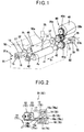
- Fig. 1 is a perspective view schematically showing a needle disposal apparatus according to a first embodiment of the present invention
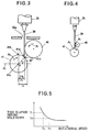
- Fig. 2 is a vertical cross-sectional view schematically showing a contact structure of the needle disposal apparatus of Fig. 1 when viewed along a direction of an arrow S 2a or S 2b .
- a needle disposal apparatus has a guide member as a part of a case 50 which has an inlet 50a for permitting a needle 24 of a used hypodermic syringe 25 to be inserted thereinto.
- the guide member may be a separate member fixed to the case 50.
- the needle disposal apparatus also has an upper electrode roller 46 formed of a material with electrical conductivity, a lower electrode roller 41 formed of a material with electrical conductivity, and a drive mechanism 80 which rotates the upper electrode roller 46 and the lower electrode roller 41 in each direction A 1 and A 2 so that the inserted needle 24 is drawn into an interstice between the upper electrode roller 46 and the lower electrode roller 41.
- Each electrode roller 46 and 41 is formed of a brass cylindrical member with chrome plating, for instance.
- the needle disposal apparatus further has an upper contact structure 81 and a lower contact structure 82.
- the upper contact structure 81 includes an upper rotary shaft 17 which is rotatably supported by a pair of bearings 37 fixed to the case 50, is formed of a material with electrical conductivity, and supports the upper electrode roller 46.
- the upper contact structure 81 also has a sleeve 18 which is formed of an alloy of silver with electrical conductivity and has an opening 18a, into which the upper rotary shaft 17 is firmly press-fitted, a contact member 15 which is formed of an alloy of silver similar to the sleeve 18 and maintains contact with an outer surface of the sleeve 18 so as to permit rotation of the upper rotary shaft 17 together with the sleeve 18.
- the contact member 15 has a V-shaped groove 15a which extends in a direction B 1 of an axis of the upper rotary shaft 17.
- An area or areas of the contact member 15 maintaining contact with the outer surface of the sleeve 18 is an inner surface of the V-shaped groove 15a of the contact member 15.
- the rotary shaft 17 as an electrical contact is disposed in concentric relationship with the electrode roller 46.
- the lower contact structure 82 has the same components as those in the upper contact structure 82.
- the lower contact structure 82 has a lower rotary shaft 77 which is formed of a material with electrical conductivity and supports the lower electrode roller 41.
- the lower contact structure 82 also has a sleeve 78 which is formed of an alloy of silver with electrical conductivity and has an opening, into which the rotary shaft 77 is firmly press-fitted, and a contact member 75 which is formed of an alloy of silver similar to the sleeve 78 and maintains contact with an outer surface of the sleeve 78 so as to permit rotation of the rotary shaft 77 together with the sleeve 78.
- the contact member 75 has a V-shaped groove 75a which extends in a direction B 1 of an axis of the rotary shaft 77.
- An area or areas of the contact member 75 maintaining contact with the outer surface of the sleeve 78 is an inner surface of the V-shaped groove 75a of the contact member 75.
- the rotary shaft 77 as an electrical contact is disposed in concentric relationship with the electrode roller 41.
- reference numerals 11 and 71 denote a crimped terminal to which a wiring leading to a battery (not shown) is connected
- reference numerals 12 and 72 denote an abutment having one arm which is connected to the terminal 11 (or 71)
- reference numerals 13 and 73 denote a springy connection plate connected to the abutment 12 (or 72) and having a reduced thickness which is formed of phosphor bronze or brass
- reference numerals 14 and 74 denote a spring disposed below the connection plate 13 (or 73) to support it from below
- reference numerals 19 and 79 denote stoppers which bear against the sleeve 18 (or 78).
- the contact members 15 and 17 are brazed to the upper surface of the connection plates 13 and 73, respectively.
- a first voltage is applied by the battery (not shown) to the upper electrode roller 46, and a lateral surface of the inserted needle 24 makes contact with an outer surface of the upper electrode roller 46.
- a second voltage which is different from the first voltage (for example, a ground voltage) is applied to the lower electrode roller 41 formed of a material with electrical conductivity. A tip of the inserted needle 24 makes contact with an outer surface of the lower electrode roller 41.
- the upper electrode roller 46 and the lower electrode roller 41 which may be simply referred to as “electrode rollers”, begin to rotate and a predetermined voltage is applied between them. If a needle 24 is inserted from the inlet 50a of the case 50 and the needle 24 makes contact with the electrode rollers 46 and 41, there occurs a current flow through the needle 24.
- the current flows from a battery (not shown) through the cable (not shown), the crimped terminal 11, the abutment 12, the connection plate 13, the contact member 15 with the V-groove 15a, the sleeve 18, the rotary shaft 17, the upper electrode roller 46, the needle 24, the lower electrode roller 41, the rotary shaft 77, the sleeve 78, the contact member 75 with the V-groove 75a, the connection plate 73, the abutment 72, the crimped terminal 71, and the cable (not shown), for instance.
- the combination of the contact member 15 (or 75) with the V-groove 15a (or 75a), the connection plate 13 (or 73a), and the spring 14 (or 74a) is effective to absorb such oscillations.
- the contact member has been constructed with a base metal in the prior art
- the contact members 15 and 75 and the sleeves 18 and 78 are constructed as a contact pair structure using similar noble metals such as an alloy of silver, which avoids a difference in the ionization tendency between them, whereby an oxide hardly forms if a high current flows. Accordingly, if the contact is subject to a sliding motion, there results a less likelihood that an insulating oxide is scraped out between the contact members 15 and 75 and the sleeves 18 and 78 to cause a poor contact.
- the V-groove 15a (or 75a) of the contact member 15 (or 75) in accordance with the present embodiment is disposed in contact with the sleeve 18 (or 78) at two points 18b and 18c (or 78b and 78b), as shown in Fig. 2, and the force acting upon either points of the outer surface of the sleeve 18 (or 78) which differ by about 90° from each other. Accordingly, for an oscillation occurring in any direction, the pressure of contact acting upon at least one of the areas of contact will be increased.
- the sleeves 18 and 78 and the rotary shafts 17 and 77 are formed of dissimilar metals, a press fit construction is used for the junction therebetween. This isolates the junction from air to inhibit the formation of oxide and also inhibits an abrasion due to minimal sliding motion therebetween. The use of an adhesive therebetween is avoided, thus preventing any resistance added. As a consequence, there is obtained an ideal contact assembly which produces a reduced heating if a high current, which may be on the order of 150 amperes in the present embodiment, flows.
- connection structures 81 and 82 mentioned above in connection with the first embodiment are not limited in its application to a needle disposal apparatus, but is also applicable to an actuator of higher current level since the connection terminal provides an enhanced reliability in feeding a higher current to a working area.
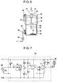
- Fig. 3 is a schematic view showing electrode rollers of a needle disposal apparatus according to a second embodiment of the present invention.
- the second embodiment is principally characterized in the positional relationship of the upper electrode roller 46, the lower electrode roller 41, and the inlet 50a of a needle.
- the fundamental construction is similar to the prior art shown in Fig. 9 or the needle disposal apparatus of Fig. 1.
- the characterizing relationship according to the second embodiment, as shown in Fig. 3, will be described below.
- the upper electrode roller 46 and the lower electrode roller 41 are disposed so that a part of the lower electrode roller 41 is hidden behind the upper electrode roller 46 when viewed from the inlet 50a provided in the case 50 in a direction of insertion of the needle 24 and the needle 24 makes contact with both the upper electrode roller 46 and the lower electrode roller 41.
- the upper electrode roller 46 is disposed so that a lateral surface of the needle 24 inserted from said inlet 50a makes contact with the outer surface of the upper electrode roller 46.
- the lower electrode roller 41 is disposed so that a tip of the needle 24 inserted from the inlet 50a makes contact with the outer surface of the lower electrode roller 41.
- a point 41a on the outer surface of the lower electrode roller 41 with which the tip of the needle 41 makes contact is between a highest position 41b from a reference plane P 1 , which is perpendicular to the direction of insertion of the needle 24 and includes a center axis 41c of said second electrode roller 41, and a position 41d which has a distance D 1 , which is 71% of a radius r 2 of the lower electrode roller 41, in a direction parallel to the reference plane P 1 from the center 41c of the lower electrode roller 41.
- the inlet 50a may be formed so that a needle 24 can be inserted in an oblique direction with reference to the vertical direction.
- the reference plane P 1 is set to be perpendicular to the direction of such insertion.
- the upper electrode roller 46 and the lower electrode roller 41 rotate toward each other, as indicated by arrows A 1 and A 2 , and rotate at the same rotational speed.
- the surface of the needle 24 is scraped by the rotating electrode rollers 46 and 41 in its regions where it is in contact with these electrode rollers 46 and 41, and the conduction of the electrical current causes a high current flow between the electrode rollers 46 and 41.
- the both electrode rollers 46 and 41 are formed of brass and have a sufficiently greater thickness than the needle 24 and thus present a lower resistance.
- the needle 24 which is formed of stainless steel presents a higher resistance.
- the surface of the needle 24 is formed with a passivation film inherent to the stainless steel, and thus presents a greater resistance of contact. Accordingly, a heating occurs in the needle 24 principally in the region of contact with the electrode rollers 46 and 41, and the needle 24 is eventually melted down to drop as a liquid.
- Molten fragments are centrifuged by the rotation of the electrode rollers 46 and 41 to fall down in a path between the electrode rollers 46 and 41, partly also involving a sputtering as a result of a rapid melting.
- a fresh portion thereof will be again brought into contact with the electrode rollers 46 and 41 to be subject to a melting action in the same manner as mentioned above. Such operation is repeated, and the needle 24 will be ultimately melted down in its entirety except for a portion thereof which cannot reach the lower electrode roller 41.
- the tip of the needle 24 is always brought into abutment against the outer surface of the lower electrode roller 41 within a range between a highest position 41b from a reference plane P 1 and a position 41d which has a distance D 1 , which is 71% of a radius r 2 of the lower electrode roller 41, in a direction parallel to the reference plane P 1 from the center 41c, and subsequently the lateral surface of the needle 24 is urged by the rotation of the lower electrode roller 41 into abutment against the upper electrode roller 46. Accordingly, the needles of a varying thickness can be disposed of. There is no need for a troublesome operation of displacing the inlet 50a in accordance with the diameter of the needle.
- the apparatus of the second embodiment is the same as that of the prior art (Fig. 10) or the first embodiment (Fig. 1).
- Fig. 4 is a schematic view showing electrode rollers of a needle disposal apparatus according to a third embodiment of the present invention
- Fig. 5 graphically shows a relationship between the time that elapsed before the melt-down and the rotational speed of the electrode roller in the third embodiment.
- the ratio of radii of the upper electrode roller 46 and the lower electrode roller 41 is different from that of the second embodiment.
- the lower electrode roller 41 has a diameter ⁇ of 8 mm while the upper electrode roller 46 has a diameter ⁇ of 6 mm.
- the electrode rollers 46 and 41 rotate at the same rotational speed and toward each other, as indicated by arrows A 1 and A 2 .
- a ratio of circumferential velocities for the electrode rollers 41 and 46 is equal to 4 : 3, whereby the lower electrode roller 41 has a speed which is by about 33% higher.
- Fig. 4 illustrates a relationship between the time elapsed before the melt-down and the rotational speed when the upper and the lower electrode rollers 46 and 41 of an equal diameter are driven for rotation at the same speed. It will be seen from Fig. 4 that the higher the rotational speed of the electrode rollers 46 and 41, the higher the melt-down capability. It will also be noted that the melt-down capability becomes constant and cannot increase any further at or greater than a given rotational speed. This means that the arrangement according to the present invention, that is, the rotation of the electrode rollers is effective.
- the choice of the circumferential velocity of the surface of the lower electrode roller 41 higher than the circumferential velocity of the surface of the upper electrode roller 46 is equivalent to saying that the melt-down performance of the lower electrode roller 41 is higher than that of the upper electrode roller 46. In other words, the melt-down operation can be substantially entirely performed by the lower electrode roller 41.
- the melt-down operation principally takes place by the lower electrode roller 41 by the choice of a higher circumferencial velocity therefor. This means that a variation which occurs in the location where the melt-down occurs is reduced. Accordingly, the occurrence of a large variation in the location of melt-down to cause a longer residue or a short residue which causes a scorching of a plastic body is eliminated. In addition, a most efficient value can be selected for the rotational speed of the electrode roller.
- the needle disposal apparatus provides a melt-down performance which remains stabilized over a prolonged length of time.
- a greater diameter is chosen for the lower electrode roller 41, but, both the upper and lower electrode rollers 46 and 41 may have an equal diameter, and a suitable gear ratio may be chosen to provide a more rapid rotation of the lower electrode roller 41.
- the apparatus of the third embodiment is the same as that of the first or second embodiment.
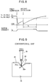
- Fig. 6 is a schematic view of a needle disposal apparatus according to a fourth embodiment of the present invention
- Fig. 7 is a circuit diagram of a control circuit of the needle disposal apparatus of Fig. 6.
- a needle 24 of a hypodermic syringe 25 is inserted through an inlet of a float 53 which moves up and down within a cylinder 52 and is depressed against the resilience of a spring 54 so that it is passed through an insertion guide 55 to be subject to a melt-down operation by a combination of a lower electrode roller 41 and an upper electrode roller 46.
- Molten fragments 61 are accumulated inside an aluminum foil 60 disposed along the inside of a dust box 59, thereby presenting no problem if they fall in an incandescent condition. Powder dust and stench are absorbed by an activated carbon filter 62, thus allowing only clean air to be discharged through an outlet 63 by a pump 64. As the syringe 25 is depressed, the float 53 releases a sensor switch 58, a signal from which opens a switch SW 1 shown in the circuit diagram of Fig. 6, thus allowing the motor 40 to be set in motion to begin rotating the electrode rollers 46 and 41. It is to be noted that all the elements in this circuit inclusive of comparators IC 1 and IC 2 constitute together an analog circuit.
- Fig. 8 is a series of timing charts illustrating the timings of operation of the needle disposal apparatus of Fig. 6.
- the switch SW 1 is opened, that is, the sensor switch 58 is released, the motor 40 is set in motion for about t 1 seconds. If the float 53 moves up and down again during t 1 seconds of operation of the motor 40, it is retriggered to operate for t 1 seconds from that time.
- the needle disposal apparatus is constructed such that as the needle 24 of the hypodermic syringe 25 is inserted, the motor current Im begins to flow so that the motor 40 begins to operate and continues to operate for a given interval of t 1 seconds, and then the motor 40 is automatically stopped.
- the needle disposal apparatus of the fourth embodiment is simple to operate because there is no need to operate the switch each time. If a needle covered by a plastic or a foreign matter is inserted into the apparatus, the latter is automatically stopped after a given time interval, thus providing a safeguard of the apparatus. Because the control circuit 66 is an analog circuit, the possibility that a malfunctioning is caused by noises which may be produced as a result of a flow of a high current during the melt-down operation is reduced, thus enhancing the reliability.
- control circuit 66 comprises analog elements.
- the circuit may be replaced by a microcomputer provided a safeguard against the malfunctioning of a logic circuit due to noises is provided.
- the apparatus of the third embodiment is the same as that of any one of the first to third embodiments.
Landscapes
- Health & Medical Sciences (AREA)
- Engineering & Computer Science (AREA)
- Life Sciences & Earth Sciences (AREA)
- Animal Behavior & Ethology (AREA)
- Anesthesiology (AREA)
- Biomedical Technology (AREA)
- Heart & Thoracic Surgery (AREA)
- Hematology (AREA)
- Environmental & Geological Engineering (AREA)
- Vascular Medicine (AREA)
- General Health & Medical Sciences (AREA)
- Public Health (AREA)
- Veterinary Medicine (AREA)
- Accommodation For Nursing Or Treatment Tables (AREA)
- Processing Of Solid Wastes (AREA)
- Apparatus For Disinfection Or Sterilisation (AREA)
- Infusion, Injection, And Reservoir Apparatuses (AREA)
Abstract
Description
Claims (13)
- A needle disposal apparatus for melting a needle (24) to be disposed of by passage of electrical current through the needle (24), said apparatus comprising:a guide member having an inlet (50a) which permits the needle (24) to be inserted;a first electrode roller (46) formed of a material with electrical conductivity, a first voltage being applied to said first electrode roller (46), the inserted needle (24) making contact with an outer surface of said first electrode roller (46);a second electrode roller (41) formed of a material with electrical conductivity, a second voltage which is different from the first voltage being applied to said second electrode roller (41), the inserted needle (24) making contact with an outer surface of said second electrode roller (41); anda drive mechanism which rotates said first electrode roller (46) and said second electrode roller (41) in each direction (A1, A2) so that the inserted needle (24) is drawn between said first electrode roller (46) and said second electrode roller (41);
wherein said first electrode roller (46) and said second electrode roller (41) are disposed so that a part of said second electrode roller (41) is hidden behind said first electrode roller (46) when viewed from said inlet (50a) of said guide member in a direction of insertion of the needle (24). - The needle disposal apparatus of claim 1, wherein said first electrode roller (46) and said second electrode roller (41) rotate in each direction so that the inserted needle (24) is drawn into an interstice between said first electrode roller (46) and said second electrode roller (41).
- The needle disposal apparatus of claim 1, wherein:said first electrode roller (46) is disposed so that a lateral surface of the needle (24) inserted from said inlet (50a) of said guide member makes contact with the outer surface of said first electrode roller (46);said second electrode roller (41) is disposed so that a tip of the needle (24) inserted from said inlet (50a) of said guide member makes contact with the outer surface of said second electrode roller (41); anda point (41a) on the outer surface of said second electrode roller (41) with which the tip of the needle (41) makes contact is between a highest position (41b) from a reference plane (P1), which is perpendicular to the direction of insertion of the needle (24) and includes a center axis (41c) of said second electrode roller (41), and a position (41d) which has a distance (D1) in a direction parallel to the reference plane (P1) from the center (41c) of said second electrode roller (41), the distance (D1) being 71% of a radius (r2) of said second electrode roller (41).
- The needle disposal apparatus of Claim 1, wherein a circumferential velocity of said second electrode roller (41) is greater than a circumferential velocity of said first electrode roller (46).
- The needle disposal apparatus of Claim 1, further comprising:a detector (58) which detects that the needle (24) is inserted into said inlet (50a) of said guide member; anda controller (66) which controls said drive mechanism so that said first electrode roller (46) and said second electrode roller (41) begin to rotate when the insertion of the needle (24) is detected and stop rotating when a predetermined time has passed from the insertion of the needle (24).
- The needle disposal apparatus of Claim 1, further comprising:a first rotary shaft (17) formed of a material with electrical conductivity and supporting said first electrode roller (46);a first sleeve (18) formed of a material with electrical conductivity and having a first opening (18a), said rotary shaft (17) being fitted into said first opening (18a) of said first sleeve (18); anda first contact member (15) formed of a material with electrical conductivity and including a first V-shaped groove (15a) which maintains contact with an outer surface of said first sleeve (18) so as to permit rotation of said first rotary shaft (17) together with said first sleeve (18).
- The needle disposal apparatus of Claim 6, wherein said first sleeve (18) is formed of an alloy of silver, and a surface of said first V-shaped groove (15a) is formed of an alloy of silver similar to said first sleeve (18).
- The needle disposal apparatus of Claim 1, further comprising:a second rotary shaft (77) formed of a material with electrical conductivity and supporting said second electrode roller (41);a second sleeve (78) formed of a material with electrical conductivity and having a second opening, said second rotary shaft (77) being fitted into said second opening of said second sleeve (78); anda second contact member (75) formed of a material with electrical conductivity and including a second V-shaped groove (75a) which maintains contact with an outer surface of said second sleeve (78) so as to permit rotation of said second rotary shaft (77) together with said second sleeve (18).
- The needle disposal apparatus of Claim 8, wherein said second sleeve (78) is formed of an alloy of silver, and a surface of said second V-shaped groove (75a) is formed of an alloy of silver similar to said second sleeve (78).
- The needle disposal apparatus of Claim 6, further comprising:a second rotary shaft (77) formed of a material with electrical conductivity and supporting said second electrode roller (41);a second sleeve (78) formed of a material with electrical conductivity and having a second opening, said second rotary shaft (77) being fitted into said second opening of said second sleeve (78); anda second contact member (75) formed of a material with electrical conductivity and including a second V-shaped groove (75a) which maintains contact with an outer surface of said second sleeve (78) so as to permit rotation of said second rotary shaft (77) together with said second sleeve (18).
- The needle disposal apparatus of Claim 10, wherein said second sleeve (78) is formed of an alloy of silver, and a surface of said second V-shaped groove (75a) is formed of an alloy of silver similar to said second sleeve (78).
- A needle disposal apparatus for melting a needle (24) to be disposed of by passage of electrical current through the needle (24), said apparatus comprising:at least one electrode roller (46, 41) formed of a material with electrical conductivity, the needle (24) making contact with an outer surface of said electrode roller (46, 41);a rotary shaft (17, 77) formed of a material with electrical conductivity and supporting said electrode roller (46, 41);a sleeve (18, 78) formed of a material with electrical conductivity and having an opening, said rotary shaft (17, 77) being fitted into said opening; anda contact member (15, 75) formed of a material with electrical conductivity and including a V-shaped groove (15a, 75a) which maintains contact with an outer surface of said sleeve (18, 78) so as to permit rotation of said rotary shaft (17, 77) together with said sleeve (18, 78).
- The needle disposal apparatus of Claim 12, wherein said sleeve (18, 78) is formed of an alloy of silver, and a surface of said V-shaped groove (15a, 75a) is formed of an alloy of silver similar to said sleeve (18, 78).
Applications Claiming Priority (2)
| Application Number | Priority Date | Filing Date | Title |
|---|---|---|---|
| JP9111798 | 1998-04-03 | ||
| JP10091117A JPH11285531A (en) | 1998-04-03 | 1998-04-03 | Contact structure and injection needle fusion cutting device |
Publications (2)
| Publication Number | Publication Date |
|---|---|
| EP0947210A2 true EP0947210A2 (en) | 1999-10-06 |
| EP0947210A3 EP0947210A3 (en) | 1999-12-08 |
Family
ID=14017587
Family Applications (1)
| Application Number | Title | Priority Date | Filing Date |
|---|---|---|---|
| EP99105856A Withdrawn EP0947210A3 (en) | 1998-04-03 | 1999-03-23 | Needle disposal apparatus |
Country Status (3)
| Country | Link |
|---|---|
| US (1) | US6169260B1 (en) |
| EP (1) | EP0947210A3 (en) |
| JP (1) | JPH11285531A (en) |
Cited By (1)
| Publication number | Priority date | Publication date | Assignee | Title |
|---|---|---|---|---|
| WO2003018090A1 (en) * | 2001-08-28 | 2003-03-06 | Saraito, S.L. | Device for destroying sharp, pointed objects which is fitted with means for automatically unscrewing injecting needles and similar |
Families Citing this family (4)
| Publication number | Priority date | Publication date | Assignee | Title |
|---|---|---|---|---|
| US6580047B1 (en) * | 1998-11-17 | 2003-06-17 | Biomedical Disposal, Inc. | Apparatus for destroying syringe-type needles by electrical current |
| US20070215578A1 (en) * | 2004-04-26 | 2007-09-20 | Softic Japan Co., Ltd. | Apparatus for Melting Off Injection Needles |
| GB0901530D0 (en) * | 2009-01-30 | 2009-03-11 | Needlesmart Holdings Ltd | Hypodermic needle destruction |
| WO2022264628A1 (en) * | 2021-06-18 | 2022-12-22 | 美らいず株式会社 | Injection needle dissolving device |
Family Cites Families (9)
| Publication number | Priority date | Publication date | Assignee | Title |
|---|---|---|---|---|
| US4870311A (en) * | 1988-10-11 | 1989-09-26 | Honeywell Inc. | Wireless slip ring assembly |
| US4961541A (en) * | 1989-09-01 | 1990-10-09 | Kabushiki Kaisha Fuso | Apparatus for disposing of a used hypodermic syringe |
| EP0644783B1 (en) * | 1992-06-11 | 1997-12-17 | ZALSTROVS, Ivars | Apparatus for the disposal of sharps |
| IT1255451B (en) * | 1992-07-01 | 1995-10-31 | DEVICE FOR THE DESTRUCTION OF SURGICAL INSTRUMENTS, IN PARTICULAR HYPODERMIC NEEDLES AND SCALPEL | |
| US5468928A (en) * | 1993-06-11 | 1995-11-21 | Inventive Services, Inc. | Portable apparatus for destroying syringe-type needles |
| US5676859A (en) * | 1995-06-27 | 1997-10-14 | Taiyo Elecs Co., Ltd. | Injection needle safety disposal apparatus |
| US5852267A (en) * | 1995-11-30 | 1998-12-22 | Taiyo Elecs Co., Ltd. | Injection needle safety disposal apparatus |
| JPH11128286A (en) * | 1997-10-30 | 1999-05-18 | Oki Data Corp | Syringe needle fusing cutter |
| US6051802A (en) * | 1998-07-21 | 2000-04-18 | Davis; Warren | Needle burner apparatus |
-
1998
- 1998-04-03 JP JP10091117A patent/JPH11285531A/en not_active Withdrawn
-
1999
- 1999-03-23 EP EP99105856A patent/EP0947210A3/en not_active Withdrawn
- 1999-03-24 US US09/274,688 patent/US6169260B1/en not_active Expired - Fee Related
Cited By (2)
| Publication number | Priority date | Publication date | Assignee | Title |
|---|---|---|---|---|
| WO2003018090A1 (en) * | 2001-08-28 | 2003-03-06 | Saraito, S.L. | Device for destroying sharp, pointed objects which is fitted with means for automatically unscrewing injecting needles and similar |
| US7024761B2 (en) | 2001-08-28 | 2006-04-11 | Saraito, S.L. | Device for destroying sharp, pointed objects which is fitted with means for automatically unscrewing injecting needles and similar |
Also Published As
| Publication number | Publication date |
|---|---|
| US6169260B1 (en) | 2001-01-02 |
| JPH11285531A (en) | 1999-10-19 |
| EP0947210A3 (en) | 1999-12-08 |
Similar Documents
| Publication | Publication Date | Title |
|---|---|---|
| US5115279A (en) | Fixing device | |
| US6169260B1 (en) | Apparatus for melting a needle using an electric current | |
| JPH07191057A (en) | Probe contact | |
| US7180219B2 (en) | DC motor with externally mounted carbon brush | |
| JPH08270654A (en) | Liquid metal plain bearings | |
| US5852267A (en) | Injection needle safety disposal apparatus | |
| US8086140B2 (en) | Photosensitive body having electrical connection arrangement | |
| KR890701804A (en) | Apparatus and method for electrochemical surface finishing of conductive metal parts | |
| US5676859A (en) | Injection needle safety disposal apparatus | |
| JP2663494B2 (en) | Surface sampling equipment for metal materials | |
| JP3521250B2 (en) | Injection needle safety processing device | |
| FR2717012A1 (en) | Dynamoelectric machine comprising a broom having an oblique core. | |
| CN110192081B (en) | Sensor head for quartz crystal oscillating film thickness monitor | |
| US5714825A (en) | Contact brush adapted to move over an electrical track associated therewith | |
| JPH05230691A (en) | Power feeder for full-surface plating device | |
| JP3877201B2 (en) | Electrode cleaning device | |
| JP2001234921A (en) | Image forming device | |
| JPS6156299A (en) | Power supply device for lating device | |
| JP3069040B2 (en) | Motor brush device | |
| US5028938A (en) | Printing head | |
| JP2002137489A (en) | Image forming device | |
| JPH08302497A (en) | Power supply roll for plating equipment and roll support mechanism | |
| JPH0651658A (en) | Fixing heater, fixing heater manufacturing method, fixing method, and fixing device | |
| JP5356708B2 (en) | Rotary connector and plating apparatus provided with the same | |
| JPH072176B2 (en) | Used needle processing equipment |
Legal Events
| Date | Code | Title | Description |
|---|---|---|---|
| PUAI | Public reference made under article 153(3) epc to a published international application that has entered the european phase |
Free format text: ORIGINAL CODE: 0009012 |
|
| AK | Designated contracting states |
Kind code of ref document: A2 Designated state(s): DE FR GB |
|
| AX | Request for extension of the european patent |
Free format text: AL;LT;LV;MK;RO;SI |
|
| PUAL | Search report despatched |
Free format text: ORIGINAL CODE: 0009013 |
|
| AK | Designated contracting states |
Kind code of ref document: A3 Designated state(s): AT BE CH CY DE DK ES FI FR GB GR IE IT LI LU MC NL PT SE |
|
| AX | Request for extension of the european patent |
Free format text: AL;LT;LV;MK;RO;SI |
|
| 17P | Request for examination filed |
Effective date: 20000608 |
|
| AKX | Designation fees paid |
Free format text: DE FR GB |
|
| STAA | Information on the status of an ep patent application or granted ep patent |
Free format text: STATUS: THE APPLICATION IS DEEMED TO BE WITHDRAWN |
|
| 18D | Application deemed to be withdrawn |
Effective date: 20021001 |