EP0945965A2 - Motor/generator - Google Patents
Motor/generator Download PDFInfo
- Publication number
- EP0945965A2 EP0945965A2 EP99105970A EP99105970A EP0945965A2 EP 0945965 A2 EP0945965 A2 EP 0945965A2 EP 99105970 A EP99105970 A EP 99105970A EP 99105970 A EP99105970 A EP 99105970A EP 0945965 A2 EP0945965 A2 EP 0945965A2
- Authority
- EP
- European Patent Office
- Prior art keywords
- rotor
- coils
- stator
- equation
- magnets
- Prior art date
- Legal status (The legal status is an assumption and is not a legal conclusion. Google has not performed a legal analysis and makes no representation as to the accuracy of the status listed.)
- Granted
Links
- 239000002131 composite material Substances 0.000 claims abstract description 8
- 230000004907 flux Effects 0.000 description 50
- 230000000694 effects Effects 0.000 description 12
- 238000010586 diagram Methods 0.000 description 9
- 238000010276 construction Methods 0.000 description 7
- 230000005284 excitation Effects 0.000 description 5
- 230000001360 synchronised effect Effects 0.000 description 4
- 230000014509 gene expression Effects 0.000 description 2
- 230000001629 suppression Effects 0.000 description 2
- 101100042630 Caenorhabditis elegans sin-3 gene Proteins 0.000 description 1
- RYGMFSIKBFXOCR-UHFFFAOYSA-N Copper Chemical compound [Cu] RYGMFSIKBFXOCR-UHFFFAOYSA-N 0.000 description 1
- 230000008859 change Effects 0.000 description 1
- 229910052802 copper Inorganic materials 0.000 description 1
- 239000010949 copper Substances 0.000 description 1
- 230000003247 decreasing effect Effects 0.000 description 1
- 238000000034 method Methods 0.000 description 1
- 230000004048 modification Effects 0.000 description 1
- 238000012986 modification Methods 0.000 description 1
- 230000035699 permeability Effects 0.000 description 1
- 229920000642 polymer Polymers 0.000 description 1
- 238000004804 winding Methods 0.000 description 1
Images


Classifications
-
- H—ELECTRICITY
- H02—GENERATION; CONVERSION OR DISTRIBUTION OF ELECTRIC POWER
- H02K—DYNAMO-ELECTRIC MACHINES
- H02K16/00—Machines with more than one rotor or stator
- H02K16/02—Machines with one stator and two or more rotors
-
- H—ELECTRICITY
- H02—GENERATION; CONVERSION OR DISTRIBUTION OF ELECTRIC POWER
- H02K—DYNAMO-ELECTRIC MACHINES
- H02K51/00—Dynamo-electric gears, i.e. dynamo-electric means for transmitting mechanical power from a driving shaft to a driven shaft and comprising structurally interrelated motor and generator parts
Definitions
- This invention relates to the structure of a motor/generator.
- Tokkai Hei 8-340663 published by the Japanese Patent Office in 1996 discloses a motor/generator comprising two rotors and one stator coaxially arranged in three layers wherein one of the rotors is driven as a motor and the other is driven as a generator.
- two sets of coils are installed in the stator for providing a magnetic field for respective rotors, and two sets of inverters, i.e., current controllers, are provided for controlling respective sets of coils.
- the coil unit is arranged so as to form plural rotating magnetic fields of equal number to the number of magnetic poles of the first rotor according to a first alternating current and to form plural rotating magnetic fields of equal number to the number of magnetic poles of the second rotor according to a second alternating current.
- Fig. 1 is a schematic cross-sectional view of a motor/generator according to this invention.
- Fig. 2 is a schematic cross-sectional view of a motor/generator comprising coils arranged on the inner circumference and outer circumference of a stator, assumed for the purpose of describing a composite current according to this invention.
- Figs. 8A-8C are diagrams showing a variation of magnetic flux density in the motor/generator of Fig. 7.
- Fig. 11 is similar to Fig. 9, but showing a case where the coils on the inner and outer circumferences are integrated.
- Fig. 20 is similar to Fig. 18, but showing a sixth embodiment of this invention.
- the permanent magnets of the outer rotor 3 do not exert a rotation force on the permanent magnets of the inner rotor 4, nor vice-versa, due to the following reason.
- the stator 2 comprises twelve coils 6wound around six cores 7.
- the cores 7 are arranged at equal intervals in a circumferential direction across gaps 9.
- each of the cores 7 is split into two parts by slits 7A, and two of the coils 6 are wound on one of the cores 7.
- These slits 7A have openings on the outer circumference of the stator 2.
- Fig. 1 For the sake of convenience, the numbers shown in Fig. 1 are assigned to these twelve coils 6. To distinguish them from part numbers, the symbol # is attached before a number as in the coil #6 to indicate a coil number.
- a current la is passed to coil #4 from coil #1, and a current la is made to flow to coil #10 from coil #7.
- a virtual coil is formed comprising coil #1 and #4 and a virtual coil is formed comprising coil #7 and #10 around the axis due to the current la.
- Control of the motor/generator 1 is performed by a controller shown in Fig. 3.
- An ON/OFF signal supplied to each gate of the inverter 12, i.e., base of the transistors, is a pulse width modulation (PWM) signal.
- PWM pulse width modulation
- the PWM signal is generated in the control circuit 15 based on positive or negative torque command values input to the control circuit 15 specifying the desired torque to be exerted on the outer rotor 3 and inner rotor 4.
- the inverter 12 can be constructed from eighteen transistors and eighteen diodes, the number of transistors and diodes can be reduced in comparison to the aforesaid first embodiment.
- Equation (11) shows that a torque fluctuation occurs only in the outer magnets.
- Equation (31) shows that the torque acting on the inner magnet m 2 varies according to the phase difference ( ⁇ + ⁇ ).
- these coils are integrated as shown in Fig. 11. specifically, the coils a and d, b and f , c and e, a and d , b and f, and c and e in Fig. 9 are respectively integrated to coils #1, #3, #5, #7, #9, #11.
- the composite currents l 1 - l 12 passed through the coils #1 -#12 in Fig. 11 are therefore set as follows due to their relation to the currents passed through the coils a, c, b and d, f,e in Fig. 9.
- Half of the current ld ' passed through the coil d' is assigned to each of the coils a and c
- half of the current Id ' passed through the coil d' is assigned to each of the coils a and c .
- coils e ', e ' and f ', f ' are assumed and the currents passing through these coils are allocated in a similar manner.
- the currents li - lxii which are the second terms on the right-hand side of the above equations for setting l 1 - l 12 , comprise a twelve-phase alternating current as shown in Fig. 12A, 12B.
- the inner rotating magnetic fields may be formed by this twelve-phase alternating current.
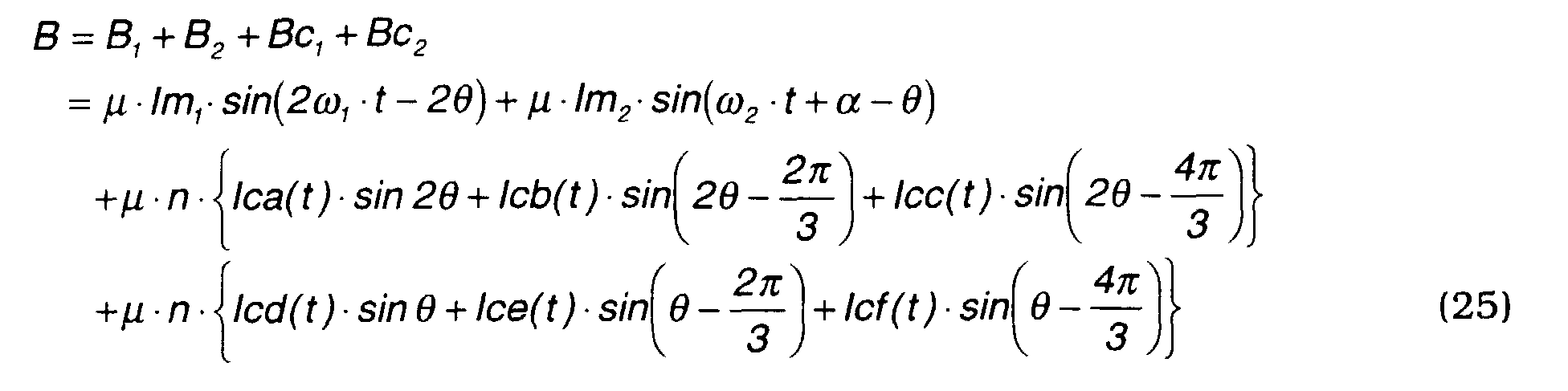
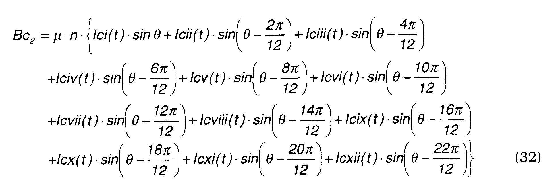
- the magnetic flux density Bc 2 when the inner rotating magnetic fields are supplied by a twelve-phase alternating current is expressed by the following equation (32).
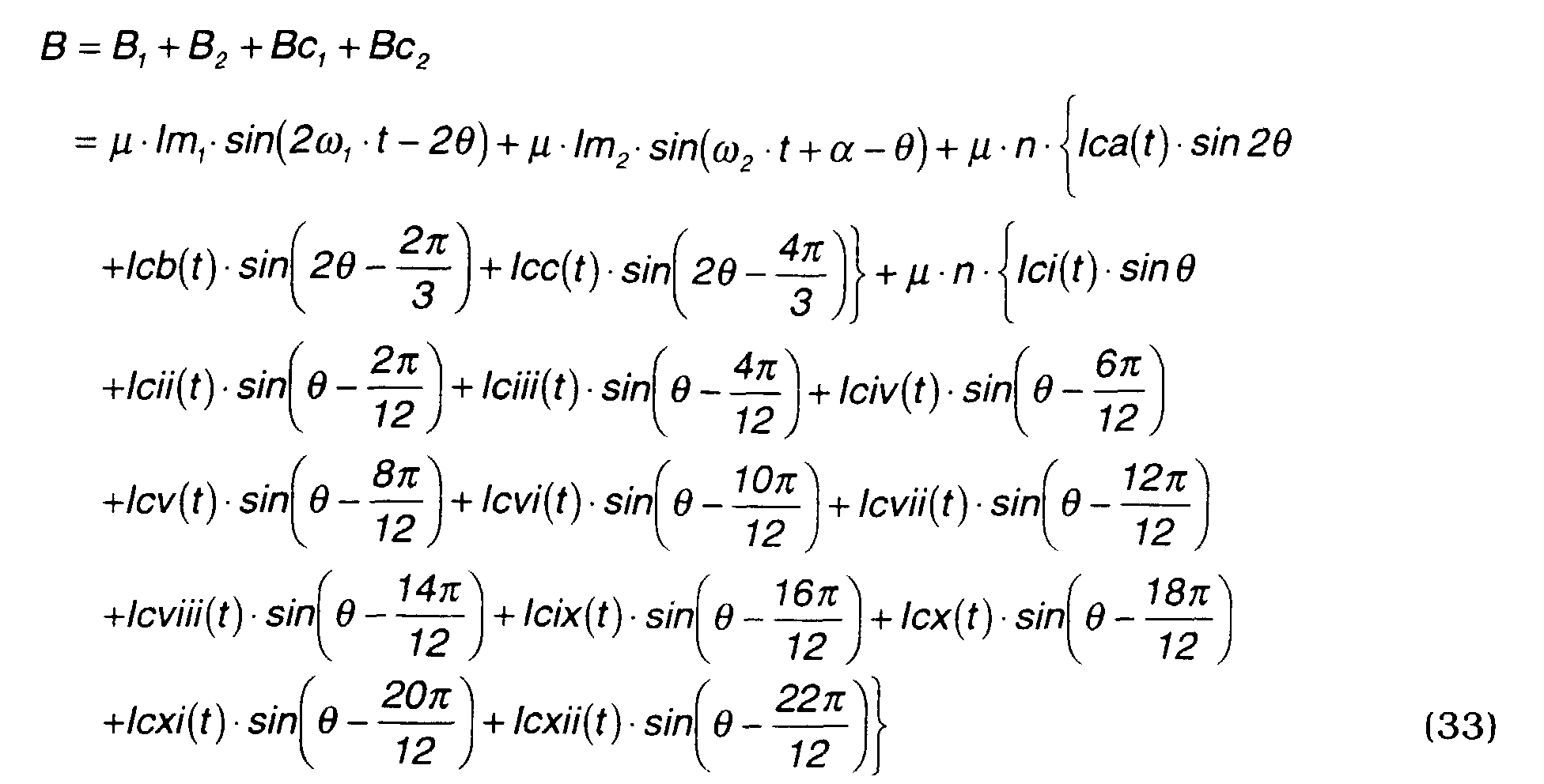
- the total magnetic flux density B is expressed by the following equation.
- the magnetic pole number ratio is 3:1 when the magnetic pole number of the outer magnets m 2 is 6 and the magnetic pole number of the inner magnets m 1 is 2.
- the magnetic flux densities B 1 and B 2 generated by the outer and inner permanent magnets are expressed by the following equations (41), (42).
- f 1 lm 1 ⁇ B 1000 + lm 1 ⁇ B 2000 - lm 1 ⁇ B 3000
- the magnetic flux density Bc 2 when the inner rotating magnetic fields are produced by nine-phase alternating current is expressed by the following equation (55).
- f 1 lm 1 ⁇ B 1000 + lm 1 ⁇ B 2000 - lm 1 ⁇ B 3000
- equation (48) As described in the case of equation (48), as in the case of three-phase alternating current, the first and second terms on the right-hand side of equation (61) are canceled when these terms in other phases are taken into account.
- equation (61) for the case where the inner rotating magnetic fields are supplied by a nine-phase alternating current is compared with the above-mentioned equation (52) where the inner rotating magnetic fields are supplied by a three-phase alternating current, the fixed term of equation (61), i.e., the last term, is three times that of equation (52).
- the drive torque required to generate the same drive torque for the inner magnets m 2 is only 1/3.
- the magnetic pole number ratio is set at 3:1.
- this invention may be applied when the magnetic pole number of the outer rotor 3 is less than or greater than the magnetic pole number of the inner rotor 4.
- the rotors were driven as a motor, however they may of course also be used as generators, or one rotor may be used as a motor and the other one may be used as a generator to generate power.
- the signal output by the control circuit 15 to the inverter is not limited to a PWM signal, and a pulse amplitude modulation (PAM) signal or other signals may be used.
- PWM pulse amplitude modulation
Abstract
Description
- This invention relates to the structure of a motor/generator.
- Tokkai Hei 8-340663 published by the Japanese Patent Office in 1996 discloses a motor/generator comprising two rotors and one stator coaxially arranged in three layers wherein one of the rotors is driven as a motor and the other is driven as a generator.
- In this motor/generator, two sets of coils are installed in the stator for providing a magnetic field for respective rotors, and two sets of inverters, i.e., current controllers, are provided for controlling respective sets of coils.
- However, in the case of this motor/generator, since two series of coils and inverters are required, there is a problem in that current losses such as copper loss and switching loss, are large.
- It is therefore an object of this invention to reduce current losses of such a three-layered motor/generator as described in the prior art.
- It is another object of this invention to simplify the construction and reduce the number of parts of such a motor/generator.
- In order to achieve the above objects, this invention provides a motor/generator, comprising a first rotor comprising plural magnetic poles and supported free to rotate, a second rotor comprising plural magnetic poles and supported free to rotate coaxially with the first rotor, a stator fixed co-axially with the first rotor, and a coil unit comprising plural coils disposed at equal angular intervals on the stator.
- The coil unit is arranged so as to form plural rotating magnetic fields of equal number to the number of magnetic poles of the first rotor according to a first alternating current and to form plural rotating magnetic fields of equal number to the number of magnetic poles of the second rotor according to a second alternating current.
- The coil unit comprises first salient poles facing the first rotor and second salient poles facing the second rotor, wherein the ratio of the first salient poles and second salient poles is set equal to the ratio of a magnetic pole number of the first rotor and a magnetic pole number of the second rotor.
- The motor/generator further comprises an electrical circuit for supplying a composite electrical current comprising the first alternating current and the second alternating current to the coil unit.
- The details as well as other features and advantages of this invention are set forth in the remainder of the specification and are shown in the accompanying drawings.
- Fig. 1 is a schematic cross-sectional view of a motor/generator according to this invention.
- Fig. 2 is a schematic cross-sectional view of a motor/generator comprising coils arranged on the inner circumference and outer circumference of a stator, assumed for the purpose of describing a composite current according to this invention.
- Fig. 3 is a schematic diagram of a control circuit according to this invention.
- Fig. 4 is a circuit diagram of an inverter according to this invention.
- Fig. 5 is a schematic cross-sectional view of a motor /generator according to a second embodiment of this invention.
- Fig. 6 is is similar to Fig. 5, but showing a third embodiment of this invention.
- Fig. 7 is a schematic cross-sectional view of a motor/generator having a magnetic pole number ratio of 1:1 set as a model for performing a theoretical analysis of magnetic flux and rotation torque.
- Figs. 8A-8C are diagrams showing a variation of magnetic flux density in the motor/generator of Fig. 7.
- Fig. 9 is a schematic cross-sectional view of a motor/generator having a magnetic pole number ratio of 2:1 and coils arranged on the inner circumference and outer circumference of a stator, assumed for the purpose of describing a composite current according to this invention.
- Figs. 10A-10D are diagrams showing a variation of magnetic flux density in the motor/generator of Fig. 9.
- Fig. 11 is similar to Fig. 9, but showing a case where the coils on the inner and outer circumferences are integrated.
- Figs. 12A-12B are diagrams showing a distribution of alternating current for driving the motor/generator of Fig. 11.
- Fig. 13 is similar to Fig. 9, but showing a case where the magnetic pole number ratio is 3:1.
- Figs. 14A - 14D are diagrams showing a variation of magnetic flux density in the motor/generator of Fig. 13.
- Figs. 15A-15C are diagrams describing magnetic force interference in the motor/generator of Fig. 13.
- Fig. 16 is similar to Fig. 13, but showing a case where the coils on the inner and outer circumferences are integrated.
- Figs. 17A, 17B are diagrams showing a distribution of alternating current for driving the motor/generator of Fig. 16.
- Fig. 18 is a schematic diagram of a motor/generator according to a fourth embodiment of this invention.
- Fig. 19 is similar to Fig. 18, but showing a fifth embodiment of this invention.
- Fig. 20 is similar to Fig. 18, but showing a sixth embodiment of this invention.
- Fig. 21 is similar to Fig. 18, but showing a seventh embodiment of this invention.
- Fig. 22 is similar to Fig. 18, but showing an eighth embodiment of this invention.
- Referring to Fig. 1 of the drawings, a motor /generator 1 has a three-layer construction comprising a cylindrical stator 2 and rotors 3, 4 arranged with a predetermined clearance outside and inside the stator 2.
- The stator 2, outer rotor 3 and inner rotor 4 are arranged coaxially. The stator 2 is fixed to a casing 41 of the motor/generator 1 as shown in Fig. 3. The outer rotor 3 is fixed to a frame 5, and the frame 5 rotates relative to the casing 41 via an axis 18. The inner rotor 4 rotates relative to the casing 41 via an axis 19.
- The inner rotor 4 comprises permanent magnets having N poles and S poles respectively arranged on each of two semicircles, as shown in Fig. 1.
- The outer rotor 3 comprises permanent magnets having a pole number two times that of the rotor 4 with two S poles and N poles alternately arranged at 90 degree intervals.
- According to this arrangement, the permanent magnets of the outer rotor 3 do not exert a rotation force on the permanent magnets of the inner rotor 4, nor vice-versa, due to the following reason.
- In the state shown in Fig. 1, assume that the S poles of the inner rotor 4 exert a rotation force in a clockwise direction on the N poles and S poles in the upper part of the drawing of the outer rotor 3. At that time, the permanent magnet N poles and S poles in the lower part of the outer rotor 3 tend to rotate in an anticlockwise direction due to the magnetic force of the N poles of the inner rotor. Therefore a rotation force acting on the N poles and S poles in upper part of drawing is offset by a rotation force acting on the N poles and S poles in the lower part of the drawing, so a rotation force does not act between the outer rotor 3 and inner rotor 4. In other words, both the outer rotor 3 and inner rotor 4 rotate only due to the magnetic force received from the stator 2.
- The stator 2 comprises twelve coils 6wound around six cores 7. The cores 7 are arranged at equal intervals in a circumferential direction across gaps 9. To reduce the total number of the cores 7, each of the cores 7 is split into two parts by slits 7A, and two of the coils 6 are wound on one of the cores 7. These slits 7A have openings on the outer circumference of the stator 2.
- As a result, two salient poles 7B, 7C are formed facing the outer rotor 3 on the outer circumference of each core 7, and one salient pole 7D is formed facing the inner rotor 4 on the inner circumference of each core 7. In total, twelve salient poles are formed on the outer circumference side, and six salient poles are formed on the inner circumference side of the whole stator 2. In other words, the total number of salient poles on the outer circumference side is equal to the total number of coils, while the total number of salient poles on the inner circumference side is a half of the total number of coils.
- For the sake of convenience, the numbers shown in Fig. 1 are assigned to these twelve coils 6. To distinguish them from part numbers, the symbol # is attached before a number as in the coil #6 to indicate a coil number.
- Currents l1 - l12 are passed into these twelve coils #1 - #12.
- First, a three phase alternating current is passed into three sets of coils to generate a rotational magnetic field relative to the inner rotor 4. Specifically, a current is passed through the coils #1, #2, #7 and #8 so as to form a virtual coil around a virtual axis which intersects perpendicularly with the rotating axis of the rotor 3 (4). For this purpose, a current Id is passed through the coils #1 and #2 in the reverse direction to the coils #7 and #8 which are situated on the opposite side of the rotation axis of the rotor 3 (4) as center. This is done by directing half a current Id through the coil #7 from the coil #1 and directing the other half of the current Id to the coil #8 from the coil #2. As the coils #1 and #2 are adjacent to each other and the coils #7 and #8 are also adjacent to each other, due to this current supply, the same situation occurs as when the current Id flows through the virtual coil mentioned above, and consequently, an N and a S pole are formed at the two ends of a virtual axis.
- Similarly, the coils #3, #4, #9, #10 form one set, and a current le flows through these coils as if they formed one virtual coil around another virtual axis rotated by 120 degrees from the aforesaid virtual axis.
- Further, the remaining coils #5, #6, #11, #12 form one virtual coil around another virtual axis rotated by 120 degrees, and a current If flows through these coils.
- Hence, three virtual coils are formed with winding axes which differ by 120 degrees, and an N pole and S pole region are formed every 180 degrees as in the case of the inner rotor 3. A three-phase alternating current is supplied to these sets of coils, and the resultant virtual coil progressively varies its polarity according to the phase of the current. As a result, two pole rotating magnetic fields are formed enclosing the inner rotor.
- In this embodiment, the flow of the current is represented in the form [#1,#2] = [#7,#8], [#3,#4] = [#9,#10], [#5,#6] = [#11,#12].
- A coil with an underlined number means that a current is passed in the reverse direction of a coil with a number which is not underlined.
- Next, a three-phase current is passed into three sets of coils by the following combination so as to generate a magnetic field relative to the outer rotor 3.
- In other words, a current la is passed to coil #4 from coil #1, and a current la is made to flow to coil #10 from coil #7. Considering a line connecting an intermediate point between coil #1 and #4 and an intermediate point between coil #7 and #10 in Fig. 1 as a virtual axis, a virtual coil is formed comprising coil #1 and #4 and a virtual coil is formed comprising coil #7 and #10 around the axis due to the current la.
- As the flow of current of these virtual coils is in opposite directions, an N pole is formed for example at the two ends of the virtual axis and an S pole is formed near the rotation axis of the rotor 3 (4) in the two sets of virtual coils. Considering this on the periphery relative to the outer rotor 3, it is equivalent to forming N poles and S poles alternately at 90 degrees intervals.
- Similarly, for coils #2, #5, #8 and #10, a current Ib is passed. Similarly, for coils #3, #6, #11 and #12, a current Ic is passed. Due to this, four-pole rotating magnetic fields are formed relative to the outer rotor 3.
- To satisfy the above conditions, the following currents l1 - l12 should be passed through the twelve coils 6.
- A current in the reverse direction is shown by underlining added to the current symbol.
- Nest, referring to Fig. 2, the determination of the currents will be described. Fig. 2 is provided for the purpose of comparison with the motor/generator in Fig. 1. In the motor/generator in Fig. 2, specific coils d, f, e are provided for rotating the inner rotor 4 and specific coils a, c, b are provided for rotating the outer rotor 3.
- In other words inner coil d, f, e form rotating magnetic fields relative to the inner rotor 4 and outer coil a, c, b form rotating magnetic fields relative to the outer rotor 3.
- To combine these two groups of coils into the one group shown in Fig. 1, of the inner coils in Fig. 2, half of the current passed into the coil d is taken up by each of the coils a and c which are in the vicinity of the coil d, half of the current passed into the coil f is taken up by each of the coils a and c which are in the vicinity of the coil f, and half of the current passed into the coil e is taken up by each of the coils c and b which are in the vicinity of the coil e. The equations for the currents l1 - l12 mentioned above are mathematical expressions of this concept. However, the currents may be set by other methods described hereafter.
- When this current setting is applied, two rotating magnetic fields can be formed simultaneously, i.e., rotating magnetic fields relative to the inner rotor 4 and rotating magnetic fields relative to the outer rotor 3, despite the use of one set of coils. Also, the rotating magnetic fields which the stator 2 forms relative to the outer rotor 3 do not give a rotational torque to the permanent magnets of the inner rotor 4, and the rotating magnetic fields which the stator 2 forms relative to the inner rotor 4 do not give a rotational torque to the permanent magnets of the outer rotor 3. This point is verified by theoretical analysis described later.
- The frequency of the currents ld, lf, le is set based on a target rotation speed of the inner rotor 4 and that of the currents la, lc, lb is set based on a target rotation speed of the outer rotor 3.
- Control of the motor/generator 1 is performed by a controller shown in Fig. 3.
- The controller comprises an inverter 12 to convert the direct current of a battery power source 11 into alternating currents in order to supply the stator 2 with the currents l1 - l12 . This inverter 12 is a twelve-phase inverter comprising twenty four transistors Tr1 - Tr24 and the same number of diodes as shown in Fig. 4. This inverter 12 may be obtained by modifying an ordinary three-phase inverter to have twelve phases.
- An ON/OFF signal supplied to each gate of the inverter 12, i.e., base of the transistors, is a pulse width modulation (PWM) signal.
- Rotation angle sensors 14 and 13 to detect the phase of the rotors 3 and 4 are installed, and signals from these sensors 13 and 14 are input into a control circuit 15.
- The PWM signal is generated in the control circuit 15 based on positive or negative torque command values input to the control circuit 15 specifying the desired torque to be exerted on the outer rotor 3 and inner rotor 4.
- In this way, in this motor/generator, two rotors 3 and 4 and one stator 2 are arranged coaxially in three layers, a series of coils 6 is provided in the stator 2, and currents are passed to these coils 6 so as to generate rotating magnetic fields inside and outside which are equal in number to the number of magnetic poles of the rotors 3 and 4.
- Therefore, when one of the rotors 3 and 4 is driven as a motor and the other is driven as a generator, a current differential between the motor drive force and the generator drive force may passed into the coils 6. It is not necessary to provide specific coils for the rotors 3 and 4 separately as in the aforesaid prior art. Hence, current losses are largely reduced.
- Further, as the rotation of two rotors 3 and 4 can be controlled by a single inverter 12, the cost of the inverter can be reduced, and as the power switching transistor capacitance of the inverter is reduced, switching efficiency improves.
- In this way, of the salient poles formed on the outer circumference and inner circumference of the stator 2, the total number of inner salient poles 7D is arranged to be a half of the total number of coils 6, so the number of the cores 7 can be reduced relative to the number of coils, and the number of components of the stator 2 can be reduced.
- Next, a second embodiment of the invention will be described referring to Fig. 5.
- According to this embodiment, the outer rotor 3 comprises six magnetic poles and eighteen of the coils 6 are used for the stator 2. In the aforesaid first embodiment, the magnetic pole number ratio of the outer rotor 3 and inner rotor 4 was 2:1, but in this embodiment, the magnetic pole number ratio is 3:1. In other words, S and N poles alternate every 60 degree in the outer rotor 3.
- In the stator 2, one core 21 is used for three coils. The stator 2 comprises six of the cores 21 arranged at an equal interval with a predetermined gap 22 on the circumference. In each core 21, two slits 21A and 21B which open toward the outer circumference are provided so as to split the core into three parts.
- Due to this, the core 21 comprises three salient poles 21C, 21D, 21E on the outer circumference and one salient pole 21F on the inner circumference. Overall, there are eighteen salient poles on the outer circumference and six salient poles on the inner circumference. In other words, the total number of salient poles on the outer circumference is equal to the number of coils 6, and the number of salient poles on the inner circumference side is one third of the total number of coils 6. In this embodiment also, the construction of the stator 2 may be simplified by reducing the number of salient poles.
- However when the magnetic pole number ratio is 3:1, unlike the case where the magnetic pole number ratio is 2:1,the permanent magnets of the inner rotor 4 are affected by the rotating magnetic fields formed by the stator 2 relative to the outer rotor 3, and a fluctuation occurs in the rotational torque of the inner rotor 4. The permanent magnets of the outer rotor 3 do not receive a rotational torque from the rotating magnetic fields formed by the stator 2 relative to the inner rotor 4, so the rotational torque of the outer rotor 3 is free from fluctuation.
- From theoretical analysis described later, this torque fluctuation is a function of the phase difference (omega1-omega2) of the outer rotor 3 and inner rotor 4. Therefore, this torque fluctuation can be canceled by previously applying an amplitude modulation to the alternating current which generates the rotating magnetic fields relative to the outer rotor 3.
- As a result, in this embodiment also, the outer rotor 3 and inner rotor 4 may basically be driven independently by a composite current as in the case when the magnetic pole number ratio is 2:1.
- Further, in this embodiment, an eighteen-phase alternating current is passed through eighteen of the coils 6. However, as the phase of the alternating current is actually reversed over half a semicircle, it is sufficient if the inverter 12 has a function to produce nine-phase alternating current. In other words, the same current is passed in the reverse direction through coils #1 and # 10, and the same current is passed in the reverse direction through coils #2 and #11, coils #3 and #12, coils #4 and #13, coils #5 and #14, coils #6 and #15, coils #7 and #16, coils #8 and #17, and coils #9 and #18.
- Due to this, as the inverter 12 can be constructed from eighteen transistors and eighteen diodes, the number of transistors and diodes can be reduced in comparison to the aforesaid first embodiment.
- Next, a third embodiment of the invention will be described referring to Fig. 6.
- This embodiment integrates six of the cores 21 of the aforesaid second embodiment as a core 31 by providing a large resistor 32 of high magnetic reluctance instead of the gap 22 of the aforesaid second embodiment.
- The large resistor 32 comprises slits 32A and 32B which are respectively provided on the outer circumference and inner circumference of the stator 2. In this embodiment, eighteen salient poles are formed on the outer circumference of the stator 2, and six salient poles are formed on the inner circumference as in the aforesaid second embodiment.
- Due to this, the number of parts and number of assembly steps of the stator 2 are decreased more than in the aforesaid second embodiment.
- The above-mentioned embodiment describe cases where the magnetic pole number ratio was 2:1 or 3:1, but it can be shown from theoretical analysis that the outer rotor 3 and inner rotor 4 can be driven using one type of the coils 6 whatever the magnetic pole number ratio may be.
- Next, the theoretical analysis of the driving forces acting on the rotors will be performed with respect to the magnetic pole number ratios.
- First, describing the notation N(2p - 2p), 2p on the left represents the number of magnetic poles of the permanent magnets of the outer rotor 3, and 2p on the right represents the number of magnetic poles of the permanent magnets of the inner rotor 4. Accordingly, the magnetic pole number ratio N(2p - 2p) means a motor/generator wherein the magnetic polymer ratio of the outer rotor 3 and inner rotor 4 is 1:1.
- N is a positive integer. If N is 1, the magnetic pole number of both the outer rotor 3 and inner rotor 4 is two, and if N is 2, the magnetic pole number of both the outer rotor 3 and inner rotor 4 is four.
- Fig. 7 shows the case of a motor/generator wherein N is 1.
- In Fig. 7, if the permanent magnets of the outer rotor 3 (hereafter abbreviated as outer magnets) m1 and the permanent magnets of the inner rotor 4 (hereafter abbreviated as inner magnets) m2 are replaced by equivalent coils, the magnetic flux densities B1, B2 of the permanent magnets may be represented by the following equations (1) and (2).
- Bm1, Bm2 = magnetic flux amplitudes,
- µ = magnetic permeability,
- lm1 = equivalent direct current of outer magnets,
- lm2 = equivalent direct current of inner magnets,
- ω 1 = rotational angular velocity of outer magnets,
- ω 2 = rotational angular velocity of inner magnets,
- α = phase difference of outer and inner magnets (when t=0), and
- t = elapsed time from time when phase of outer magnets and stator coil coincided.
-
- If the current passed through the stator is a three-phase alternating current, the magnetic flux density Bc due to the stator coil is expressed by the following equation (3).where, n = coil constant.

- In equation (3), Ica(t), Icb(t), Icc(t) are currents which are different in phase by 120 degrees.
- The variation of the aforesaid magnetic flux densities B1, B2 and Bc is shown in Figs. 8A - 8C. The magnetic flux density changes as a sine-wave, and a total magnetic flux density B at an angle _ is expressed by the following equation (4).

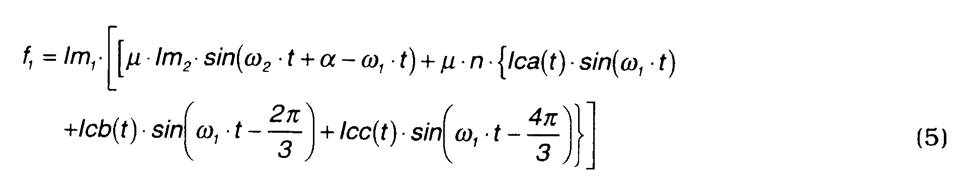
- Here, let the torque acting on the outer rotor 3 be τ 1 . If the force which acts on a semicircle of the outer rotor 3 is f1, the force which then acts the other semicircle is also f1 . Accordingly, the force acting on the whole circumference is 2f1, and the torque τ 1 may be expressed by the following equation.
- Here, the force f1 is a drive force which occurs when a direct current lm1 is generated in a magnetic field of magnetic flux density B. From the above equation, it is seen that there is a directly proportional relation between the torque τ1 and the drive force f1. As an equivalent direct current is formed for each semicircle, f1 is given by the following equation.
- From this equation and equation (4), f1 may be expressed by the following equation (5).
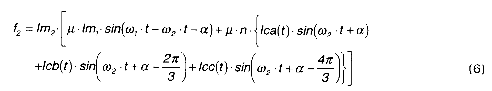
- Similarly, if the force acting on the semicircle of the inner rotor 4 is f2, the force acting on the whole rotor is 2f2 , so the torque τ 2 acting on the inner magnets m2 may be expressed by the following equation.
- Here, the force f2 is the drive force due to an equivalent direct current lm2 in a magnetic field of magnetic flux density B. As an equivalent direct current is formed for each semicircle, f2 is given by the following equation.
- From this equation and equation (4), f2 may be expressed by the following equation (6)
- In order to pass currents in the coils a, b, c each of which has a phase difference of β with respect to the rotating outer magnets m1 , alternating currents Ica(t), Icb(t), Icc(t) in equation (3) are set by the following equations (7A) - (7C).
 where,
- lc = amplitude of alternating currents, and
- β = phase difference.
-
- The drive force f1, f2 is calculated by substituting equations (7A) - (7C) in equations (5) - (6).

- Here, the above equation may be rewritten using the formula

- Equation (8) has a form wherein the first term which is a torque fluctuation amount due to the effect of the magnetic field of the inner agnets is added to the second term which is a constant torque.
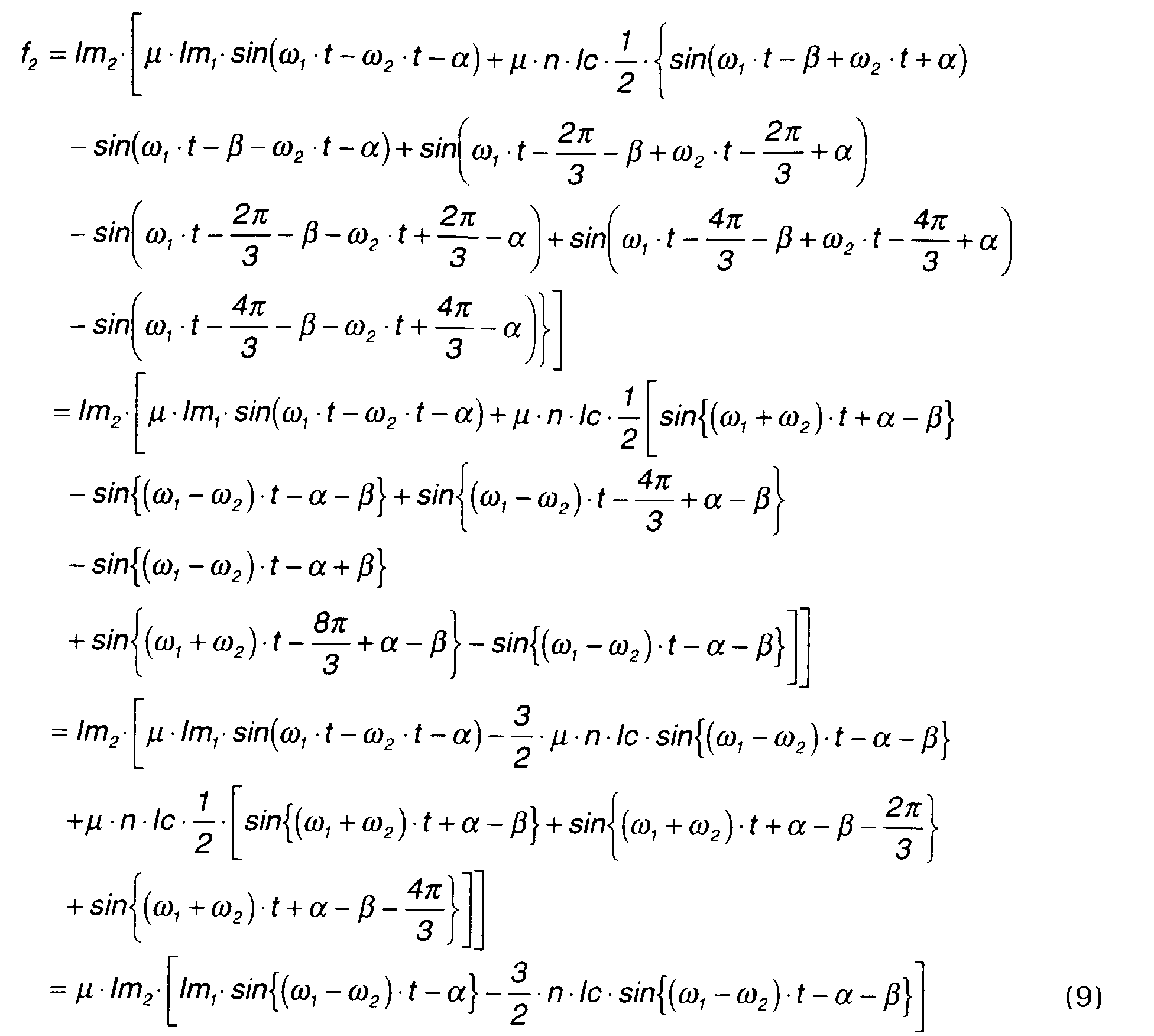
- Also, f2 may be rewritten by the following equation.
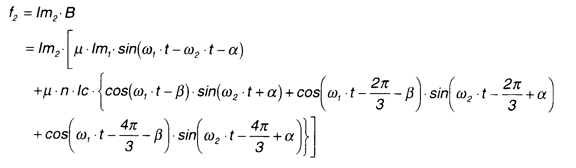
- Here, the above equation may be rewritten using the formula
- In order to pass currents in the coils a, b, c each of which has a phase difference of γ with respect to the rotating inner magnets m2 , alternating currents Ica(t), Icb(t), Icc(t) in the above equation (3) are set by the following equations (10A) - (10C).
 where,
- Ic = amplitude of alternating currents, and
- γ = phase difference.
-
- The drive force f1 , f2 is calculated by substituting equations (10A)-(10C) in equations (5) -(6).

- Here, the above equation may be rewritten using the formula
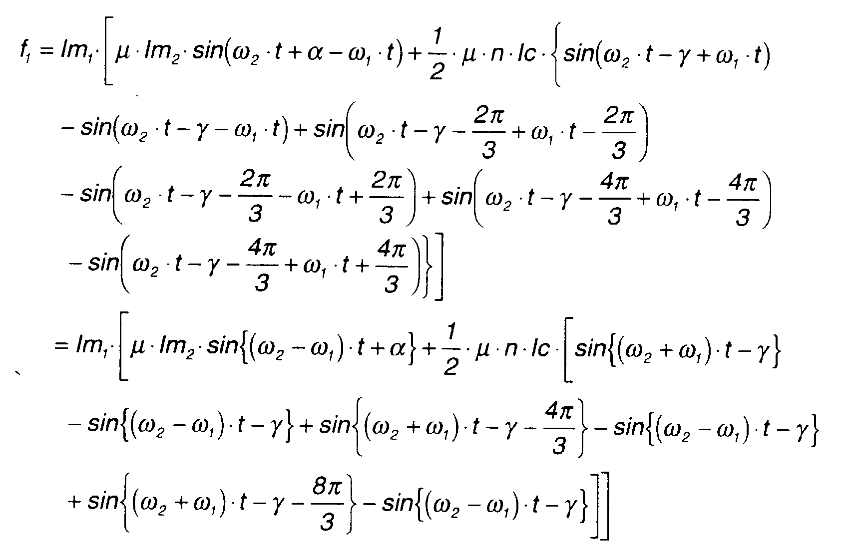
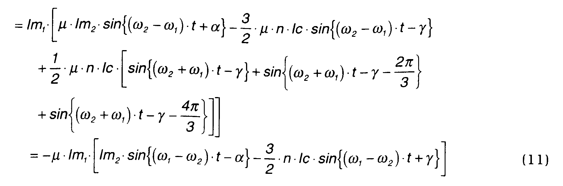
- Equation (11) shows that a torque fluctuation occurs only in the outer magnets.
- Also, f2 may be rewritten by the following equation.
- Here, the above equation may be rewritten using the formula

- Equation (12) has a form wherein the first term which is a torque fluctuation amount due to the effect of the magnetic field of the inner magnets is added to the second term which is a constant torque.
- The above Ica(t), Icb(t), Icc(t) are set to pass a current through the coils 6 in synchronism with the outer magnets and inner magnets.

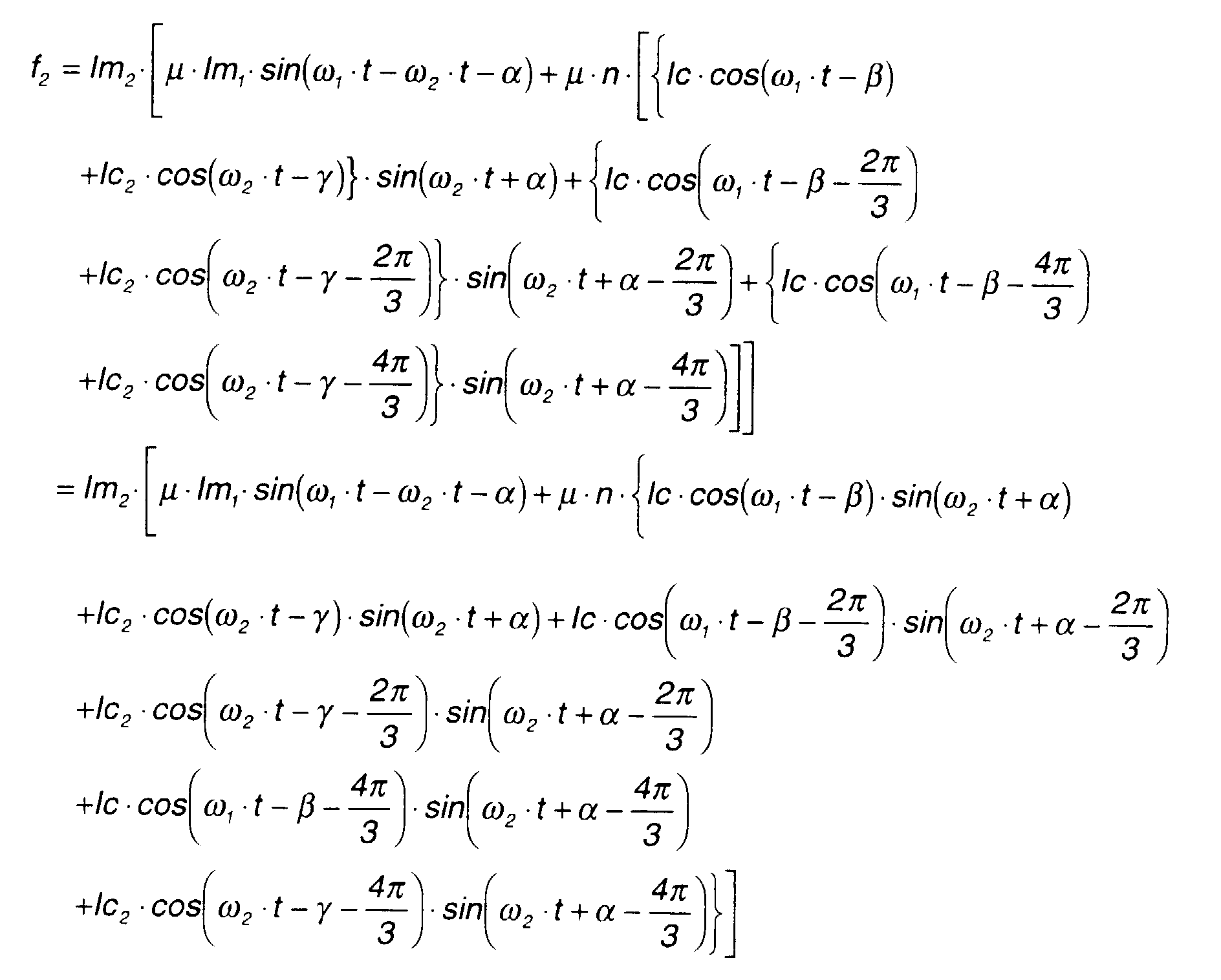
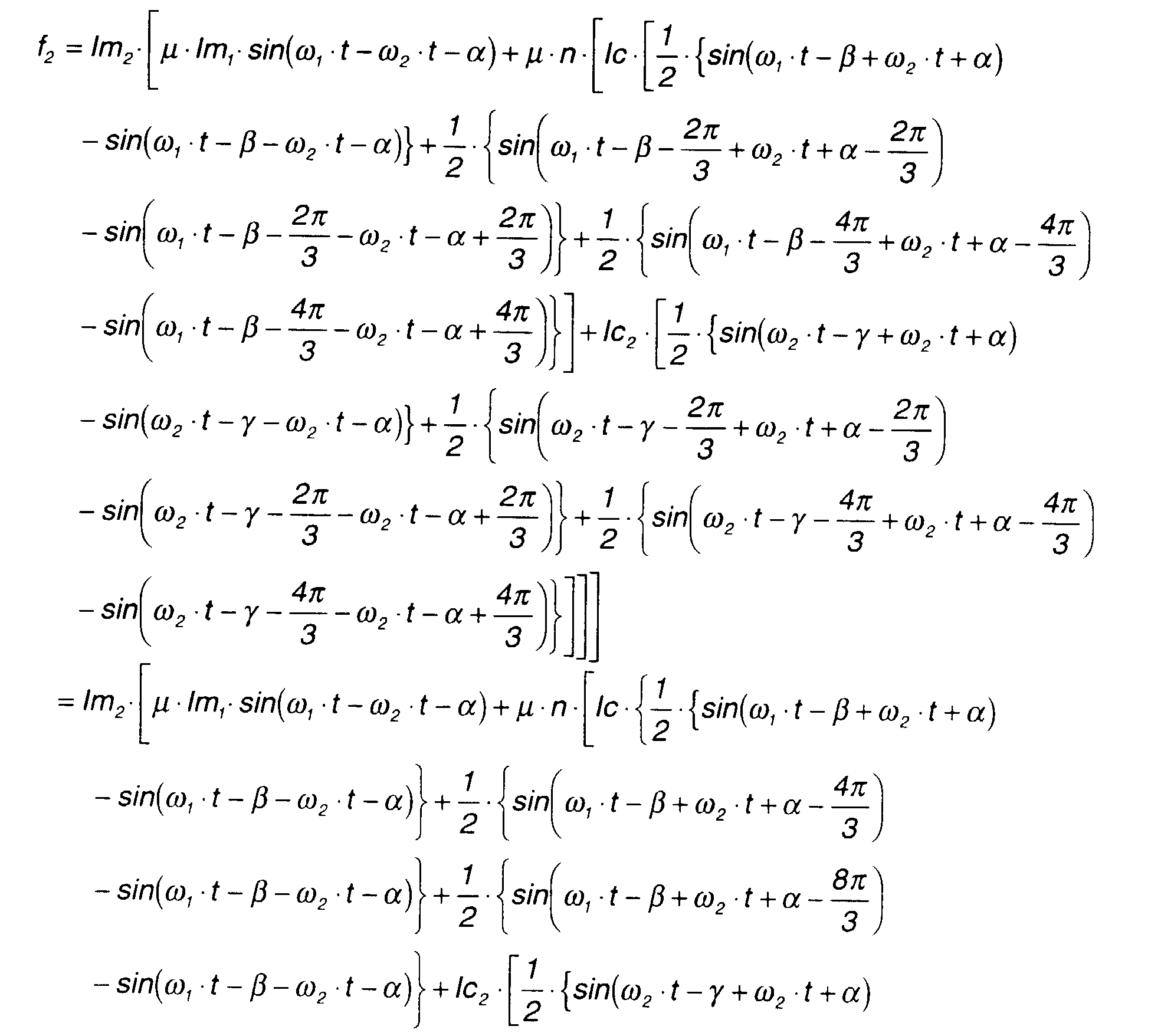
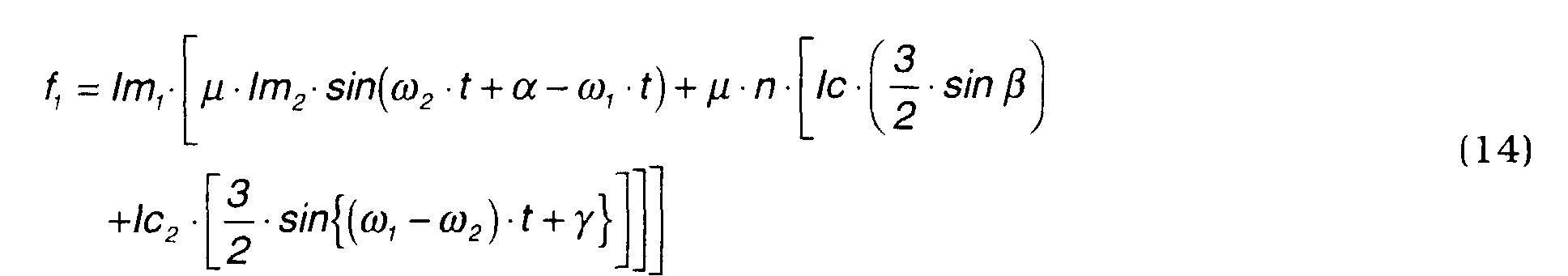
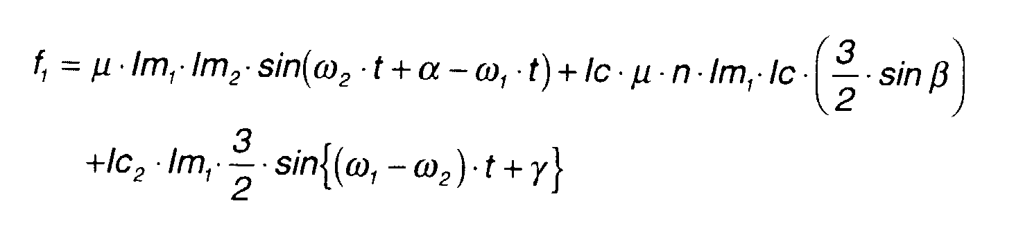
- The drive forces f1, f2 are calculated by the following equations (14), (15).

- Equation (14) has a form wherein a torque fluctuation is added to a constant torque according to a rotation phase difference β relative to the outer magnets m1 .

- Here, the above equation may be rewritten using the formula

- Equation (15) also has a form wherein a torque fluctuation is added to a constant torque rotation phase difference (α+γ) relative to the inner magnets m2 .
- The above-mentioned equations (8),(9),(11),(12),(14),(15) may be summarized as follows.
- When the outer rotating magnetic fields are applied


- When the inner rotating magnetic fields are applied


- When the outer rotating magnetic fields and inner rotating magnetic fields are applied together

- The meaning of these equations is as follows.
- The second term on the right-hand side of equation (8), the second term on the right-hand side of equation (12), the second term on the right-hand side of equation (14) and the third term on the right-hand side of equation (15) are fixed terms, i.e., constant values, and a rotational torque occurs only when these constant terms are present. Terms other than the constant terms are trigonometric functions, and the average value of a drive force fn which does not comprise a fixed term is zero. In other words, a rotational torque does not occur due to terms other than fixed terms.
- Comparing equations (8) and (9), only f1 from equation (8) comprises a constant torque. In other words, when a current is passed through the coils 6 of the stator 2 in synchronism with the rotation of the outer magnets, a rotational torque acts only the outer magnets..
- Comparing equations (11) and (12), only f2 from equation (12) comprises a constant torque. In other words, when a current is passed through the coils 6 of the stator 2 in synchronism with the rotation of the inner magnets, a rotational torque acts only the inner magnets.
- Comparing equations (14) and (15), f1 from equation (14) and f2 from equation (15) both comprise a constant torque. In other words, when a current synchronized with the rotation of the outer magnets and a current synchronized with the rotation of the inner magnets are passed together through the coils 6, rotational torques corresponding to the respective currents act on the outer and inner magnets.
- It is seen from the above facts that, when the magnetic pole number ratio is 1:1, the two rotors 3,4 can be driven as a generator and a motor simultaneously using only one series of coils 6. Further, it may be surmised that the same operation is possible for any magnetic pole number ratio.
- Due to terms other than fixed terms in the equations containing fixed terms, i.e., due to the first term on the right-hand side of equation (8), and the first and third terms on the right-hand side of equation (14), a torque fluctuation appears in the outer magnets rotation due to the phase difference (ω 1 -ω 2 ) between the inner magnets and outer magnets.
- Also, due to the first term on the right-hand side of equation (12), and the first and second terms on the right-hand side of equation (15), a torque fluctuation appears in the inner magnets rotation due to the phase difference (ω 1 -ω 2 ) between the inner magnets and outer magnets.
- Now, the suppression of torque fluctuation will be considered when both the outer rotating magnetic fields and an inner rotating magnetic fields are applied.
- Equation (14) may be rewritten as follows.
- Here, f1 may be written as follows.

- Here, if a modulation of Ic = C1 -A-Ic2 ·V / C is added, f1 =C1 (constant) and the torque fluctuation is eliminated from the rotation of the outer magnets.
- Similarly, equation (15) may be rewritten as follows.
- Here, f2 may be written as follows.
- Here, if a modulation of lc2 = C2 + A-Ic·D / Eis added, f2 = C2 (constant) and the torque fluctuation is eliminated from the rotation of the inner magnets.
- Therefore to give both permanent magnets a constant rotation, the following two simultaneous second order equations regarding Ic and lc2 should be solved.
- In this way, in the composite current, the torque fluctuation in the rotation of the rotors can be eliminated by adding an amplitude modulation to the alternating current which generates rotating magnetic fields that produce a torque fluctuation.
- Taking the motor/generator of Fig. 9 as an example, when the magnetic pole number of the outer magnets is 4 and the magnetic pole number of the inner magnets is 2, the magnetic pole number ratio is 2:1. In this construction, if the permanent magnets are magnetically replaced by an equivalent coil, a magnetic flux density B1 generated by the outer magnets is expressed by the following equation (21).
- The magnetic flux density B 2 generated in the inner magnets is expressed by equation (22) which is equivalent to the equation (2).
- It may be considered that the coils are arranged as shown in Fig. 9 so as to calculate the magnetic field produced by the coils 6 of the stator 2 separately for the outer rotating magnetic fields which rotate the outer rotor 3 and the inner rotating magnetic fields which rotate the inner rotor 4.
- Magnetic flux densities Bc1, Bc2 of the outer coils and inner coils are expressed by the following equations (23), (24).
 where, lcd(t), lce(t), lcf(t) are also currents which are different in phase by 120 degrees as in the case of lca(t), lcb(t), Icc(t).
- Next, the change of magnetic flux density B1, B2, Bc1, Bc2 mentioned above will be described referring to Figs. 10A - 10D.
- The magnetic flux density B at an angle _ is the sum of the aforesaid four magnetic flux densities.
- Here, if the total torque acting on the outer rotor 3 is τ1, the following equation holds.
- In the construction of Fig. 9, unlike the case of Fig. 7, the torques exerted on each of the outer magnets m1 are not symmetrical. Therefore the force f1 is considered to be a total force acting on each of four equivalent direct currents that correspond to the outer magnets m1 . This relation is expressed by the following equation.
- B10 is magnetic flux density B at = ω 1 ·t,
- B20 is magnetic flux density B at = ω 1 ·t+π,
- B30 is | magnetic flux density B at in = ω 1 ·t+π/2 , and
- B40 is magnetic flux density B at = ω 1 ·t+3π/2.
-
- Therefore, the above equation can be rewritten as follows.
- Equation (26) shows that the torque acting on the outer magnets m1 due to the exciting currents of the coils a, b, c can be controlled, and that it is not affected by the exciting currents of the coils d, e, f.
- Next, if the torque acting on the inner rotor 4 is τ 2 , the following equation holds.
- The torques acting on the inner magnets m2 of the inner rotor 4 are not symmetrical. Therefore, the force f2 is considered to be a total force acting on each of two equivalent direct currents that correspond to the inner magnets. This relation is expressed by the following equation.
- B100 is magnetic flux density B when = ω 2 ·t + α, and
- B200 is magnetic flux density B when = ω 2 ·t + π + α.
-
- Therefore, the above equation may be rewritten as follows.


- According to the equation (27), the torque acting on the inner magnets m2 due to the excitation currents of the coils d, e, f can be controlled, and the torque acting on the inner magnets m2 is not affected by the excitation currents of the coils a, b, c.
- Currents with a phase difference of β with respect to the rotation position of the outer magnets m1 are passed through the coils a, b, c. In order to generate the above currents, the alternating currents Ica(t), Icb(t), Icc(t) mentioned above may be defined by the following equations.


- Next, (28A)-(28C) are substituted in equations (26) (27) to calculate f1 .

- Here, the above equation may be rewritten as the following equation (29) using the formula
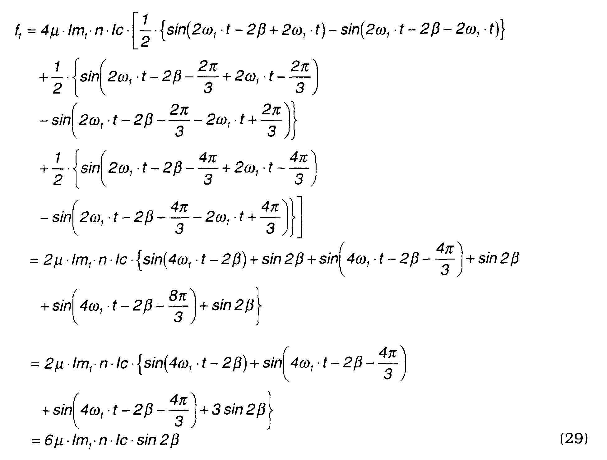
- Equation (29) shows that the torque acting on the outer magnet m1 varies according to the phase difference β. Therefore, the rotation position of the outer magnets m1 should be measured and excitation currents shifted in phase by β should be applied to the coils a, b, c.
- Currents with a phase difference of γ with respect to the rotation position of the inner magnets m2 are passed through the coils d, e, f.
- In order to generate the above currents, the alternating currents Icd(t), Ice (t), Icf(t) mentioned above may be defined by the following equations.


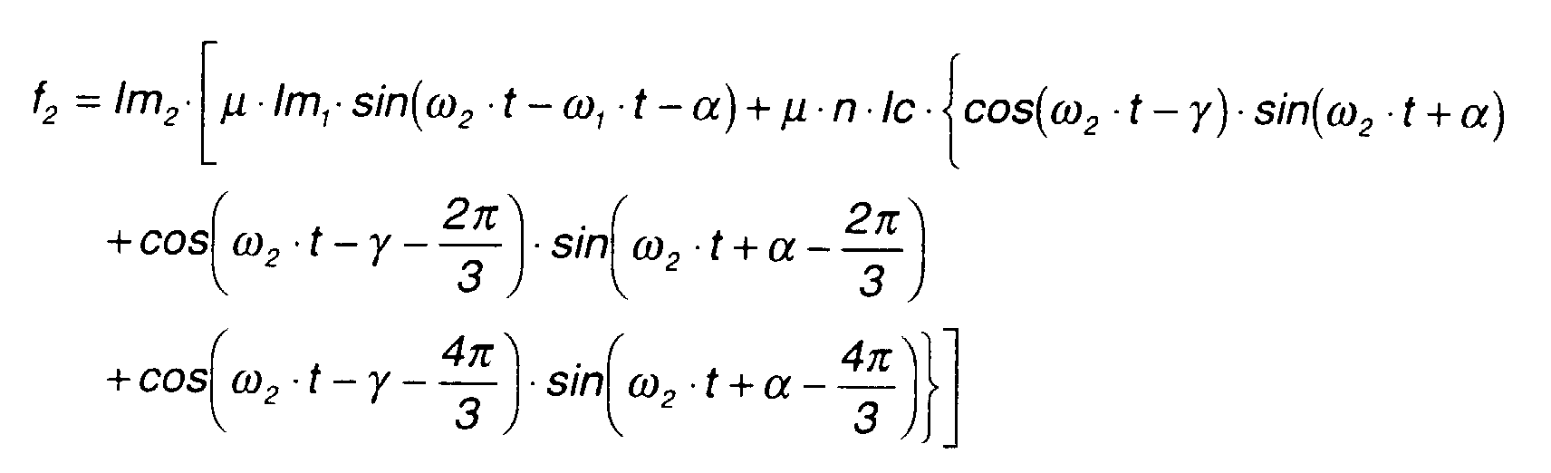
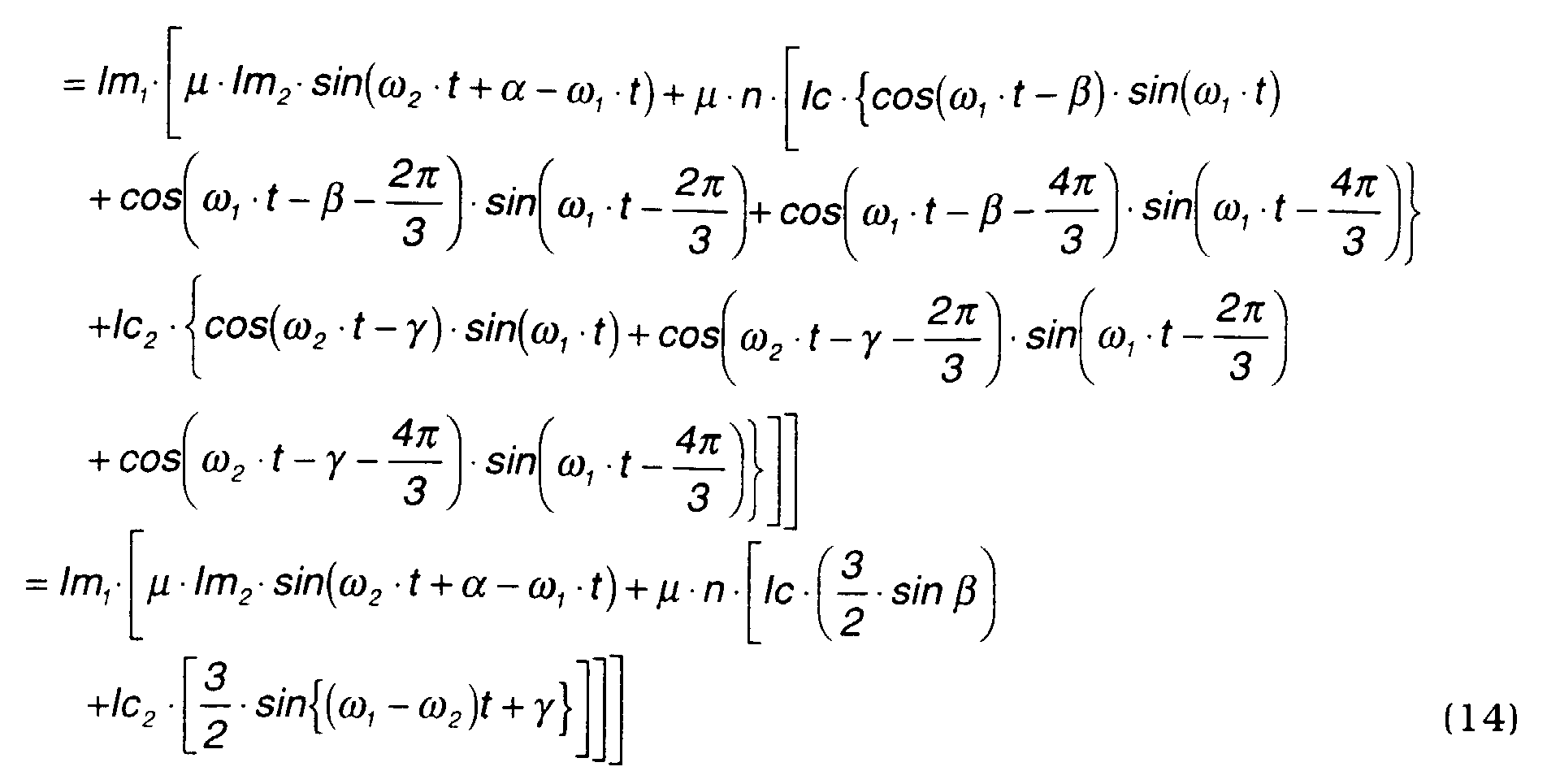
- Next, (30A) - (30C) are substituted in equations (27) to calculate f2.

- Here, the above equation may be rewritten using the formula


- Equation (31) shows that the torque acting on the inner magnet m2 varies according to the phase difference (γ+α).
- Therefore, the rotation position of the inner magnets m2 should be measured and excitation currents shifted in phase by (γ+α) should be applied to the coils d, e, f.
- Equation (29) shows that when currents are passed through the coils 6 of the stator 2 in synchronism with the outer magnets m1 , a rotational torque acts only the outer magnets m1 .
- Equation (31) shows that when currents are passed through the coils 6 in synchronism with the outer magnets m2 , a rotational torque acts only the outer magnets m2 .
- Although the calculations are not shown, when a current synchronized with the rotation of the outer magnets and a current synchronized with the rotation of the inner magnets are passed together through the coils 6, rotational torques corresponding to the respective currents act on the outer and inner magnets as in the case where the magnetic pole number ratio is 2:1, as described in (1-4).
- This fact shows that also in the case where the magnetic pole number ratio is 2:1, the two rotors 3, 4 can be driven as a generator /motor using the coils 6.
- In this case, as only constant terms remain, there is no fluctuation of rotation torque of the inner rotor 4 due to the effect of the outer rotor 3 or the rotational magnetic field produced to drive the outer rotor 3, and conversely, there is no fluctuation of rotation torque of the outer rotor 3 due to the effect of the inner rotor 4 or the rotational magnetic field produced to drive the inner rotor 4.
- In other words, when the magnetic pole number ratio is 2:1, both rotors can be driven with a constant rotation, without adding an amplitude modulation to eliminate torque fluctuation as when the magnetic pole number ratio is 1:1, or as described later, 3:1.
- In Fig. 9, a series of coils a, c, b for generating the outer rotating magnetic fields and another series of coils d, f, e for generating the inner rotating magnetic fields are assumed for the purpose of theoretical calculation.
- In the real motor/generator according to this invention, these coils are integrated as shown in Fig. 11. specifically, the coils a and d, b and f, c and e, a and d, b and f, and c and e in Fig. 9 are respectively integrated to coils #1, #3, #5, #7, #9, #11. The composite currents l1 - l12 passed through the coils #1 -#12 in Fig. 11 are therefore set as follows due to their relation to the currents passed through the coils a, c, b and d, f,e in Fig. 9.
- In this case, the load on the coils through which the currents l1 , l3 , l5 , l7 , l9 , l11 are passed is greater than that of the remaining coils through which the currents l2 , l4, l6, l8, l10 are passed. Therefore, it is considered to spread the load among the remaining coils in order to form the inner rotating magnetic fields.
- For example, comparing Fig. 2 and Fig. 1, the coils in Fig. 2 corresponding to 1, 1, 2, 2 in Fig. 1 are the outer coils a, a , c, c and the inner coils d, d. In this case, it is assumed that the position of the coils d, d is shifted to a position that is equidistant from the coil a, a and the coil c , c. These shifted coils are designated as coils d', d'.
- Half of the current ld' passed through the coil d' is assigned to each of the coils a and c , and half of the current Id ' passed through the coil d' is assigned to each of the coils a and c. Similarly coils e', e' and f', f' are assumed and the currents passing through these coils are allocated in a similar manner.
- In this way, the following alternative current settings are possible:
- Alternatively, the following settings are possible.
- The currents li - lxii which are the second terms on the right-hand side of the above equations for setting l1 - l12, comprise a twelve-phase alternating current as shown in Fig. 12A, 12B. The inner rotating magnetic fields may be formed by this twelve-phase alternating current.
- The magnetic flux density Bc2 when the inner rotating magnetic fields are supplied by a twelve-phase alternating current is expressed by the following equation (32).
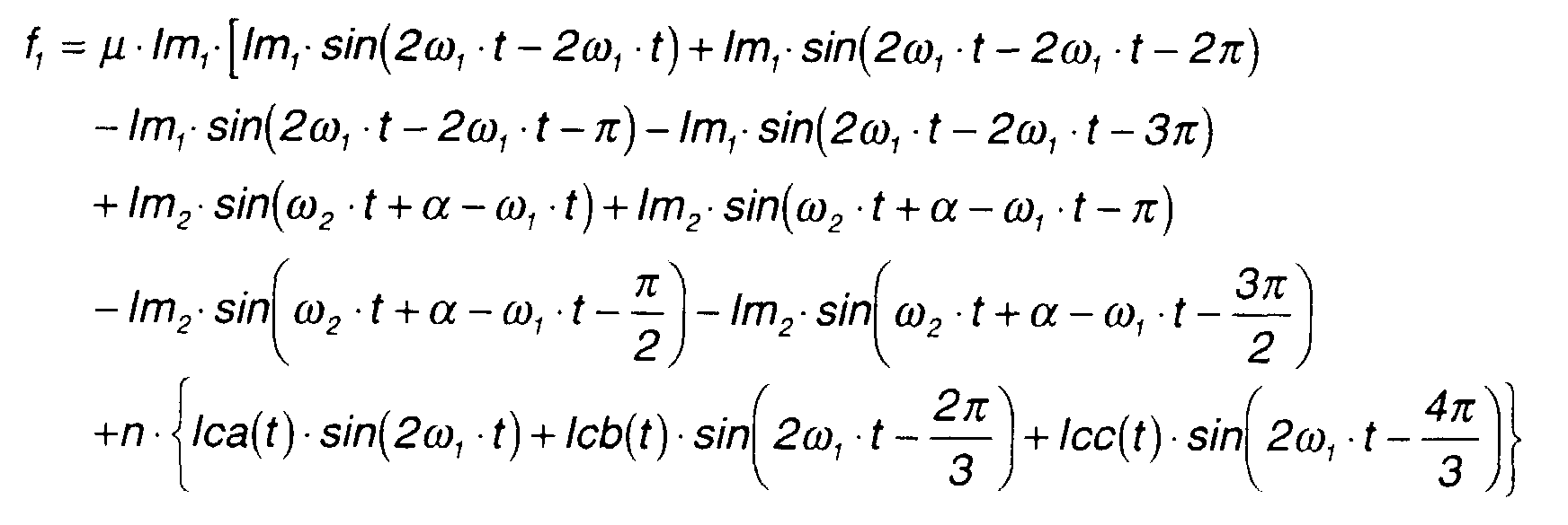
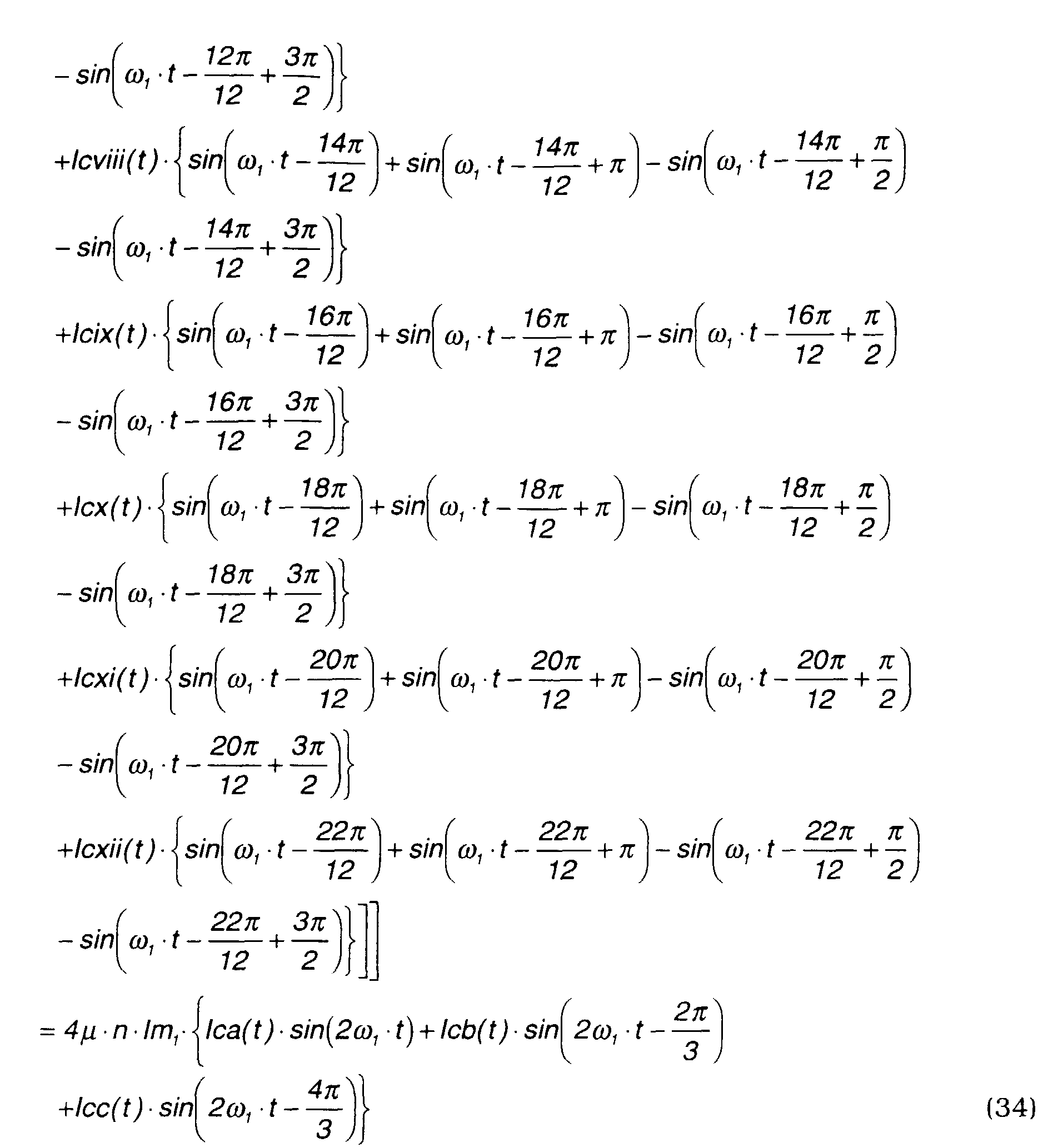
- The total magnetic flux density B is expressed by the following equation.f1 is calculated by the following equation.
- B10 is magnetic flux density B at = ω 1 ·t,
- B20 is magnetic flux density B at = ω 1 ·t+π,
- B30 is | magnetic flux density B at = ω 1 ·t+ π/2, and
- B40 is magnetic flux density B at = ω 1·t+ 3π/2 .
-
- Therefore, the above equation can be rewritten as follows.

- This is the same as equation (26) where the inner rotating magnetic fields are produced by a three-phase alternating current.
- Also, f2 is calculated by the following equation.
- B100 is magnetic flux density B at = ω2·t+α, and
- B200 is magnetic flux density B at = ω2·t + π + α.
-
- Therefore, the above equation can be rewritten as follows.
 f2 given by this equation (35) is different from f2 given by equation (27) when the inner rotating magnetic fields are formed by a three-phase alternating current. Therefore, the following calculation of f2 when the inner rotating magnetic fields are formed by a twelve-phase alternating current, will be performed.
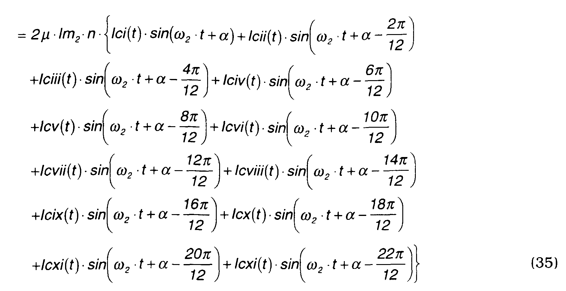
- The above-mentioned twelve-phase alternating current lci(t)- lcxii(t) is set by the following equations (36A) - (36L).


 f2 is calculated by substituting equations (36A) - (36L) in equation (35).

- Here, the above equation may be rewritten using the formula


- Comparing equation (37) obtained when the inner rotating magnetic fields are supplied by a twelve-phase alternating current with the above-mentioned equation (31) obtained when the inner rotating magnetic fields are supplied by a three-phase alternating current (31), the constant term of equation (37), i.e., the last term, is four times that of equation (31).
- In other words, when the inner magnet is driven by a twelve-phase alternating current (li - lxii), the drive torque obtained is four times that when the inner magnet is driven by a three-phase alternating current.
- In other words, the inner magnets drive current required to exert the same drive torque on the inner *magnets m2 , is only one fourth of that when a three-phase alternating current is applied.
- Taking a motor/generator of Fig. 13 as an example, the magnetic pole number ratio is 3:1 when the magnetic pole number of the outer magnets m2 is 6 and the magnetic pole number of the inner magnets m1 is 2.
- In this construction, the magnetic flux densities B1 and B2 generated by the outer and inner permanent magnets are expressed by the following equations (41), (42).
- The rotating magnetic fields produced by the coils 6 of the stator 2 are calculated separately for the outer rotor 3 and inner rotor 4. The magnetic flux densities Bc1, Bc2 of the coils 6 relative to the outer magnets m1 and inner magnets m2 are expressed by the following equations (43), (44).


- The variation of the aforesaid magnetic flux densities B1, B2 and Bc, Bc2 are shown in Figs. 14A - 14D.
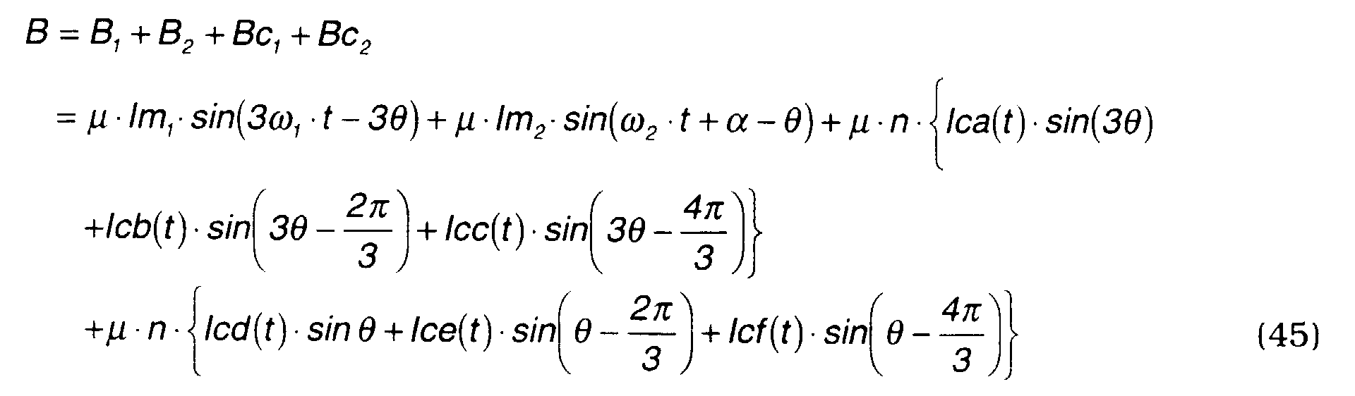
- The total magnetic flux density B is expressed by the following equation.
- Here, let the torque acting on the outer rotor 3 be τ 1 . If the force which acts on a semicircle of the outer rotor 3 is f1 , the force which then acts on the other semicircle is also f1 . Therefore, the force acting on the whole circumference is 2f1, and the torque τ 1 may be expressed by the following equation.
- As three equivalent direct currents are formed for one semicircle, f1 is given by the following equation.
- B1000 is magnetic flux density B at = ω 1 ·t,
- B2000 is | magnetic flux density B at = ω 1 ·t + 2π/3, and
- B3000 is magnetic flux density B at = ω 1 ·t+π/3.
-
- Therefore, the above equation can be rewritten as follows.


- Equation (46) shows that when the magnetic flux density of the outer magnets m1 is approximated to a sine wave, the torque acting on the outer magnets m1 can be controlled by the exciting currents of the coils a, b, c.
- It also shows that the torque acting on the outer magnets m1 is not affected by the excitation currents of the coils d, e, f.
- Here, let the torque acting on the inner rotor 4 be τ 2 . If the force which acts on a semicircle of the inner rotor 4 is f2 , the force which then acts the other semicircle is also f2 . Therefore, the force acting on the whole circumference is 2f2 , and the torque τ 2 may be expressed by the following equation.
- Here, the force f2 is a drive force which an equivalent direct current lm2 generates in a magnetic field of magnetic flux density B. As an equivalent direct current is formed for each semicircle, f2 is given by the following equation.
- From this equation and equation (45), f2 may be expressed by the following equation (47).

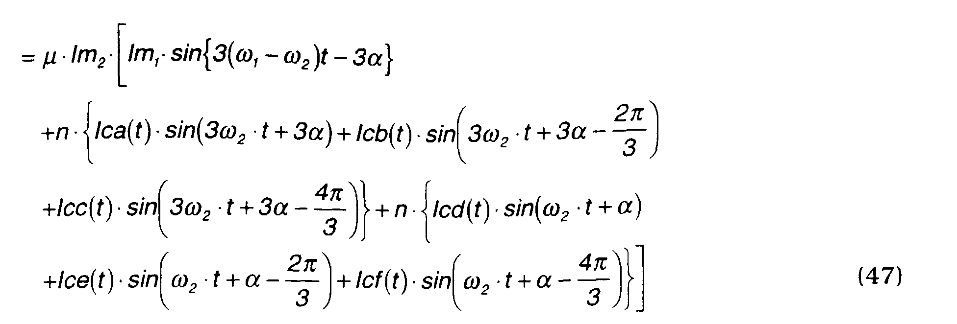
- The second term in equation (47) shows that the torque acting on the inner magnets m2 is evidently affected by the exciting currents of the coils a, b, c for the outer magnets m1 . However, this is an apparent effect, and there is actually no effect due to the following reason.
- If the positions of the outer magnets m1 are 1 = ω 1 ·t + π/6, 2 = ω1 ·t + 5π/6, 3 = ω1 ·t + 9π/6 respectively, the magnetic flux density B1 of the outer magnets m1 at a rotation angle may be expressed by the following equation.

- This shows that the magnetic poles formed at 120 degree intervals cancel the magnetic force. In other words, the magnetic pole number of the outer magnets m1 has no effect on the inner magnets m2 . Similarly, the magnetic flux density produced by the outer coil is also 0 in total. Therefore, the drive force f2 is as follows.


- The alternating currents Ica(t), Icb(t), Icc(t) and alternating currents Icd(t), Ice(t), Icf(t) are expressed by the following equations.


- In equations (50A) - (50C), to permit amplitude modulation, the current is assumed to be Ic2 (t) which is a function of time t.
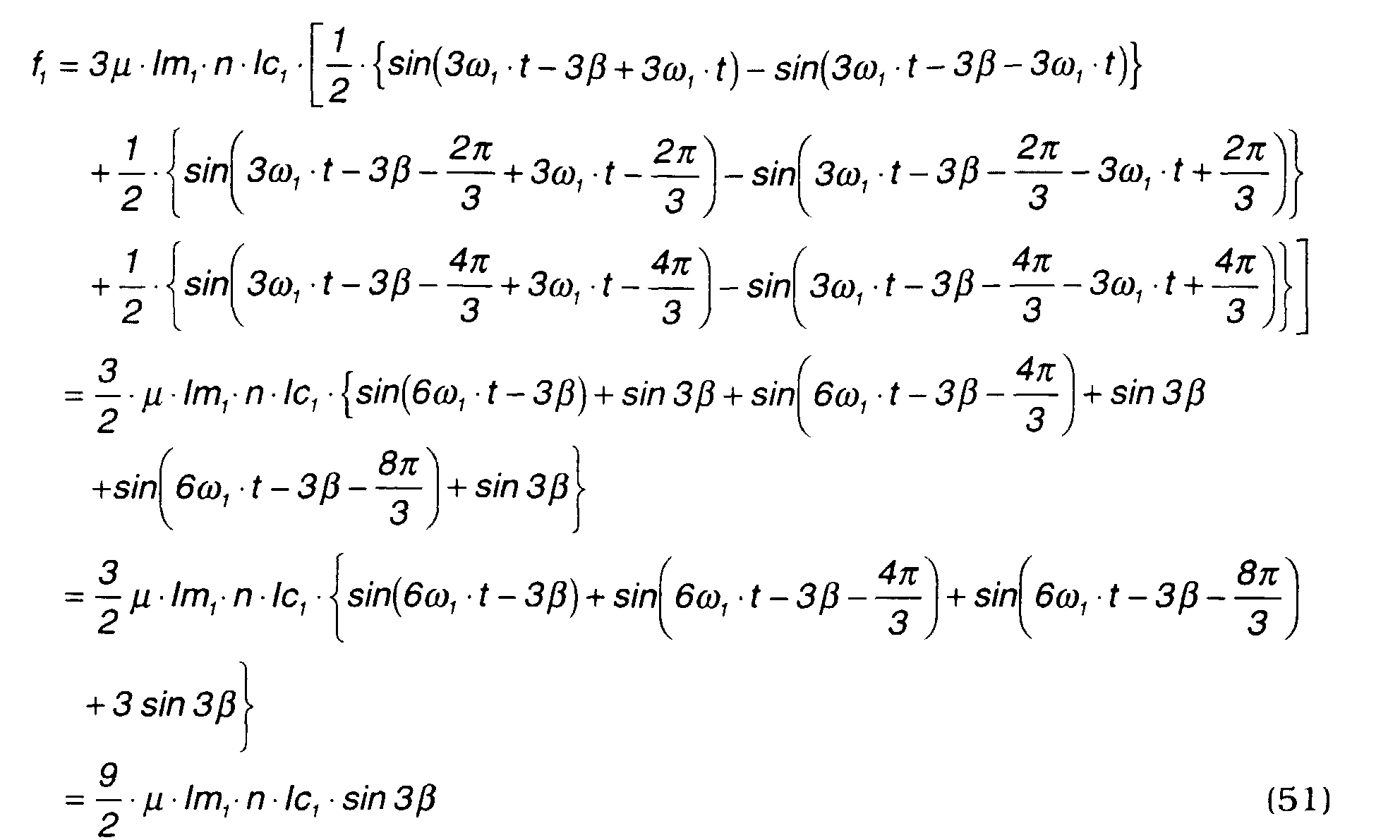
- f1, f2 are calculated by substituting equations (49A) - (49C) in equation (46), and substituting equations (49A) - (49C) and (50A) - (50C) in equation (47).

- Here, the above equation may be rewritten using the formula

- Here, the above equation may be rewritten using the expression


- As described with regard to equation (48), f2 is a constant value when there is no effect of the outer magnets m1 and outer coils a, c, b as shown by the following equation (53).
- Conversely, when there is an effect from the magnetic field due to the outer magnets m1 and outer coils, if lc2 (t) is set by the following equation (54), ff2 =C (constant) in the equation (52) and the motor/generator can be driven by a constant torque.
- In other words, this means that according to equation (52), some effect of the outer magnets m1 is generated relative to the rotation of the inner magnets m2 when the magnetic pole number ratio is 3:1. More precisely, a constant torque fluctuation based on the phase difference (ω 1 - ω 2 ) occurs in the rotational torque of the inner magnets m2 . This situation is shown in Figs. 15A - 15C.
- If a magnetic field is assumed to be rectangular in a model representation, the magnetic force interference between the outer magnets and inner magnets may be clearly expressed.
- Comparing state A with state B, as state B is stable, a torque is generated in state A which tends to shift to state B. This torque is an intermittent torque and is generated by a phase difference (ω 1 - ω 2 ). Further, as a perfect sine wave cannot be realized due to the effect of distance between coils, it may be impossible to completely eliminate the effect of the outer magnets. The most extreme example of such case is expressed by equation (52). However, a torque fluctuation can be eliminated in most cases by applying amplitude modulation from equation (54), and the inner magnet can be driven with a constant torque even when the magnetic pole number ratio is 3:1.
- According to equations (51), (52), when currents are passed through the coils of the stator 2 in synchronism with the rotations of the outer magnets m1 and inner magnets m2 , a rotational torque acts on both permanent magnets.
- It will of course be understood that when currents are passed through the coils of the stator in synchronism with the rotation of the outer magnets m1, a rotational torque acts only the outer magnets m1, and when currents are passed through the coils of the stator in synchronism with the rotation of the inner magnets m2 , a rotational torque acts only the inner magnets m2 .
- This fact shows that also in the case where the magnetic pole number ratio is 3:1, the two rotors 3, 4 can be driven as a generator and a motor using one series of the coils 6.
- In Fig. 13, one series of coils a, c, b are assumed to generate the outer rotating magnetic fields, and another series of coils d, f, e are assumed to generate the inner rotating magnetic fields.
- In the real motor/generator according to this invention, these coils are integrated as shown in Fig. 16. Specifically, the coils a and d, a and f, a and e, a and d, a and f, a and e in Fig. 13 are respectively integrated to coils #1, #4, #7, #1, #4 and #7.
- In view of the construction of Fig. 16, the currents passing through the coils 6 of the stator 2 may be set as follows.
I1 = Ia +Id I10 = I1 = Ia + Id I2 = lc I11 = I2 = lc I3 = lb I12 = I3 = Ib I4 = Ia + If l13 = I4 = la + If I5 = lc I14 = l5 = lc l6 = lb I15 = l6 = Ib l7 = la +le l16 = la + le l8 = lc l17 = l8 = lc l9 = lb l18 = l9 = lb - When the magnetic pole number ratio is 3:1, an eighteen-phase alternating current is required, but the phase is reversed over half the circumference, so a nine-phase alternating current (half of eighteen-phase) may be used.
- In this case as the load on coils #1, #4, #7, #1, #4 and #7 is heavy, it is desirable to use also the remaining coils in order to form the inner rotating magnetic fields. For example, the following current settings are recommended.
l1=la + li l10=l1 =la + li l2=lc + lvi l11=l2 =lc + lvi l3=lb + lii l12 = l3 =lb + lii l4=la + Ivii I13=l4=Ia+Ivii l5=lc + liii l14=l5 =lc + liii l6=lb + lviii l15 = l6 =lb + lviii l7 =la +liv l16 =l7 =la + liv l8=lc + lix l17=l8=lc + lix l9=lb + lv l18=l9=lb + Iv - The phases of the currents li - lix and li - lix for forming the inner rotating magnetic fields are shown in Figs. 17A and 17B.
- The magnetic flux density Bc2 when the inner rotating magnetic fields are produced by nine-phase alternating current is expressed by the following equation (55).

- The total magnetic flux density B is expressed as follows.
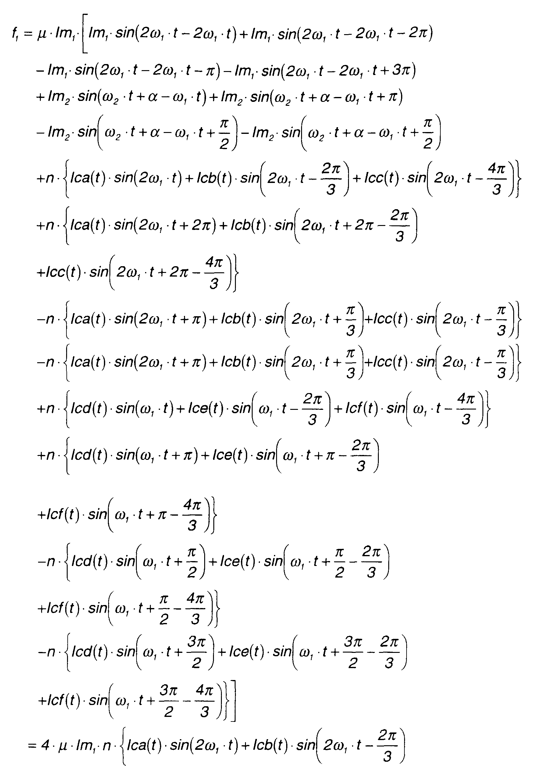
 f1 is calculated by the following equation.
- B1000 is magnetic flux density B at = ω 1·t,
- B2000 is magnetic flux density B at = ω 1 ·t+2π/3, and
- B3000 is magnetic flux density B at = ω 1 ·t+π/3.
-
- Therefore, the above equation can be rewritten as follows.


- This is the same as equation (46) which is obtained when the inner rotating magnetic fields are supplied by a three-phase alternating current.
- On the other hand, f2 may be calculated as follows.
- From this equation and equation (56), f2 may be expressed by the following equation.

- The three-phase alternating currents Ica(t), Icb(t), Icc(t) mentioned above are expressed by the following equations (59A), (59B), (59C).


- The nine-phase alternating currents lci(t)- lcix(t) mentioned above are set as follows.


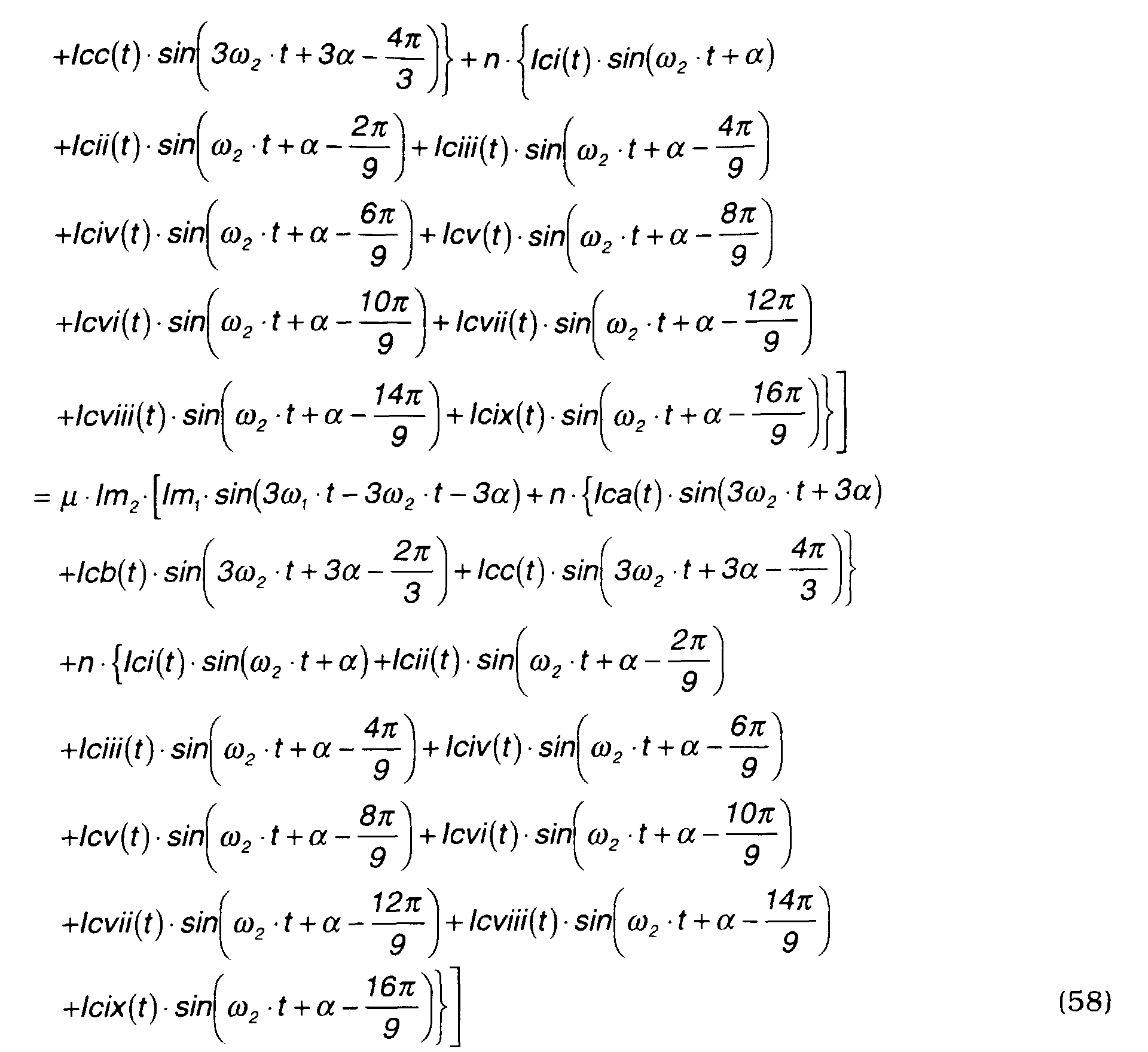
- Next, f2 is calculated by substituting equations (59A) - (59C) and equations (60A) - (60I) into equation (58).

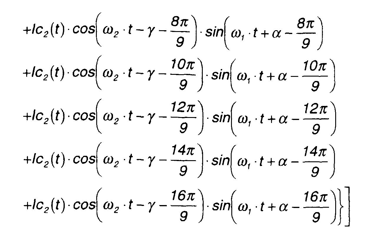
- Here, the above equation may be rewritten using the formula
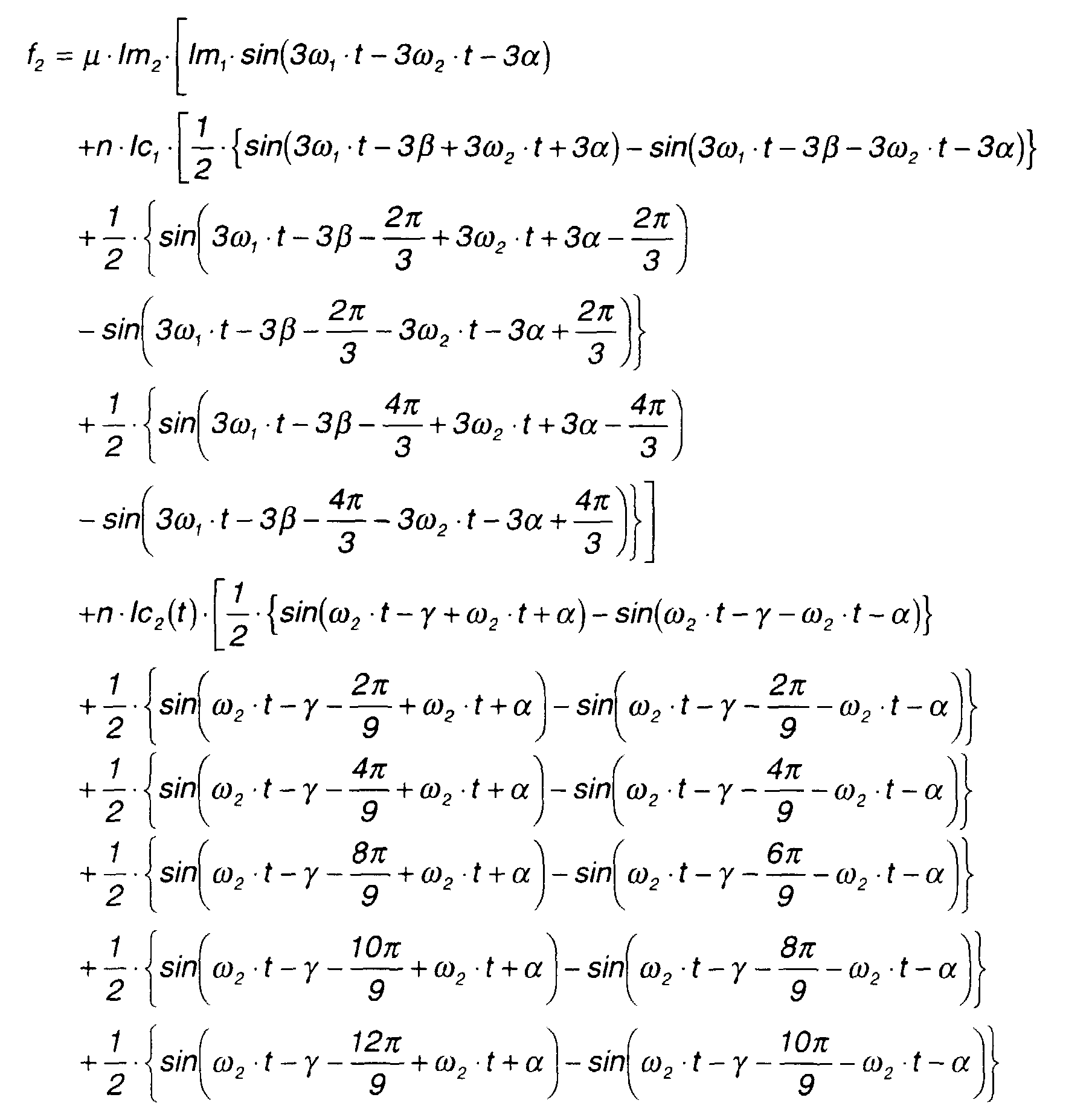

- As described in the case of equation (48), as in the case of three-phase alternating current, the first and second terms on the right-hand side of equation (61) are canceled when these terms in other phases are taken into account.
- When this equation (61) for the case where the inner rotating magnetic fields are supplied by a nine-phase alternating current is compared with the above-mentioned equation (52) where the inner rotating magnetic fields are supplied by a three-phase alternating current, the fixed term of equation (61), i.e., the last term, is three times that of equation (52).
- In other words, when the drive current of the inner magnets m2 is a nine-phase alternating current (li - lix), a drive force, i.e., drive torque, is three times that when the drive current of the inner magnet is a three-phase alternating current.
- In other words, the drive torque required to generate the same drive torque for the inner magnets m2 is only 1/3.
- This completes the theoretical analysis of this invention.
- Finally, fourth-eighth embodiments of the invention will be described referring to Figs. 18 - 22. Here too, the inner rotor 4 is arranged inside the stator 2 and the outer rotor 3 is arranged outside the stator 2 as in the above-mentioned first-third embodiments, and the magnetic pole number ratio of the outer rotor 3 and inner rotor 4 is varied.
- In the fourth embodiment shown in Fig. 18, the magnetic pole number ratio is set at 2:1.
- In the fifth embodiment shown in Fig. 19, the magnetic pole number ratio is set at 2:1.
- In the sixth embodiment shown in Fig. 20, the magnetic pole number ratio is set at 3:1.
- In the seventh embodiment shown in Fig. 21, the magnetic pole number ratio is set at 9:1.
- In the eighth embodiment shown in Fig. 22, the magnetic pole number ratio is set at 3:1.
- Hence, this invention may be applied when the magnetic pole number of the outer rotor 3 is less than or greater than the magnetic pole number of the inner rotor 4.
- In Figs. 18 - 22, several salient poles are not shown, but the ratio of outer salient pole number to inner salient pole number is set to be the same as the magnetic pole number ratio of the outer rotor 3 and inner rotor 4. Specifically, it is set at 2:1 in the fourth embodiment shown in Fig. 18 and fifth embodiment shown in Fig. 19. It is set at 3:1 in the sixth embodiment shown in Fig. 20 and eighth embodiment shown in Fig. 22. In the seventh embodiment shown in Fig. 21, it is set at 9:1.
- In the description of the above embodiments, the case was described where the rotors were driven as a motor, however they may of course also be used as generators, or one rotor may be used as a motor and the other one may be used as a generator to generate power.
- The contents of Tokugan Hei 10-77465, with a filing date of March 25, 1998 in Japan, are hereby incorporated by reference. Although the invention has been described above by reference to certain embodiments of the invention, the invention is not limited to the embodiments described above. Modifications and variations of the embodiments described above will occur to those skilled in the art, in light of the above teachings.
- For example, in the above embodiments, the rotors 3 and 4 were arranged outside and inside the stator 2, but both rotors may be arranged outside the stator 2 or inside the stator 2.
- Also, the signal output by the control circuit 15 to the inverter is not limited to a PWM signal, and a pulse amplitude modulation (PAM) signal or other signals may be used.
- This invention is not limited to a radial gap type motor/generator wherein the gap between the rotor and the stator is set in a radial direction, and may be applied to a motor/generator wherein the gap between the rotor and stator is in an axial direction.
- The embodiments of this invention in which an exclusive property or privilege is claimed are defined as follows:
Claims (4)
- A motor/generator, comprising:a first rotor (3) comprising plural magnetic poles and supported free to rotate,a second rotor (4) comprising plural magnetic poles and supported free to rotate coaxially with said first rotor (3),a stator (2) fixed co-axially with said first rotor (3),a coil unit (6) comprising plural coils disposed at equal angular intervals on said stator (2) so as to form plural rotating magnetic fields of equal number to the number of magnetic poles of said first rotor (3) according to a first alternating current and to form plural rotating magnetic fields of equal number to the number of magnetic poles of said second rotor (4) according to a second alternating current, said coil unit (6) comprising first salient poles (7B, 7C, 21C, 21D, 21E) facing said first rotor (3) and second salient poles (7D, 21F) facing said second rotor (4), wherein the ratio of said first salient poles (7B, 7C, 21C, 21D, 21E) and second salient poles (7D, 21F) is set equal to the ratio of a magnetic pole number of said first rotor (3) and a magnetic pole number of said second rotor (4), andan electrical circuit (11, 12, 13, 14, 15) for supplying a composite electrical current comprising said first alternating current and said second alternating current to said coil unit (6).
- A motor/generator as defined in Claim 1, wherein the number of said first salient poles (7B, 7C, 21C, 21D, 21E) is larger than the number of said second salient poles (7D, 21F), said second salient poles (7D, 21F) are divided by gaps (9, 22) which divide said stator 2, and said first salient poles (7B, 7C, 21C, 21D, 21E) are divided by said gaps (9, 22) and slits (7A, 21A, 21B) formed in said stator 2.
- A motor/generator as defined in Claim 1, wherein the number of said first salient poles (7B, 7C, 21C, 21D, 21E) is larger than the number of said second salient poles (7D, 21F), said second salient poles (7D, 21F) are divided by a large resistor (32) provided in said stator 2, and said first salient poles (7B, 7C, 21C, 21D, 21E) are divided by said resistor (32) and slits (21A, 21B) formed in said stator 2.
- A motor/generator as defined in Claim 3, wherein said stator (2) is formed in a cylindrical shape comprising an inner circumference and outer circumference, and said large resistor (32) comprises two slits (32A, 32B) formed on said inner circumference and outer circumference.
Applications Claiming Priority (2)
| Application Number | Priority Date | Filing Date | Title |
|---|---|---|---|
| JP7746598 | 1998-03-25 | ||
| JP07746598A JP3480301B2 (en) | 1998-03-25 | 1998-03-25 | Rotating electric machine |
Publications (3)
| Publication Number | Publication Date |
|---|---|
| EP0945965A2 true EP0945965A2 (en) | 1999-09-29 |
| EP0945965A3 EP0945965A3 (en) | 2002-11-27 |
| EP0945965B1 EP0945965B1 (en) | 2003-11-05 |
Family
ID=13634756
Family Applications (1)
| Application Number | Title | Priority Date | Filing Date |
|---|---|---|---|
| EP99105970A Expired - Lifetime EP0945965B1 (en) | 1998-03-25 | 1999-03-24 | Motor/generator |
Country Status (4)
| Country | Link |
|---|---|
| US (1) | US6211597B1 (en) |
| EP (1) | EP0945965B1 (en) |
| JP (1) | JP3480301B2 (en) |
| DE (1) | DE69912505T2 (en) |
Cited By (6)
| Publication number | Priority date | Publication date | Assignee | Title |
|---|---|---|---|---|
| EP1096648A2 (en) * | 1999-10-27 | 2001-05-02 | Nissan Motor Co., Ltd. | Motor/generator having two rotors |
| EP1117173A2 (en) * | 2000-01-17 | 2001-07-18 | Nissan Motor Company Limited | Motor/Generator |
| EP1191673A2 (en) * | 2000-09-14 | 2002-03-27 | Denso Corporation | Compact and reliable structure of multi-rotor synchronous machine |
| US6998757B2 (en) | 2000-09-14 | 2006-02-14 | Denso Corporation | Multi-rotor synchronous machine permitting relative movement between rotors |
| EP3007336A1 (en) * | 2014-10-07 | 2016-04-13 | C.R.F. Società Consortile per Azioni | Synchronous electric machine with two rotors |
| EP3355446A1 (en) * | 2017-01-27 | 2018-08-01 | Toyota Jidosha Kabushiki Kaisha | Rotary electric machine |
Families Citing this family (43)
| Publication number | Priority date | Publication date | Assignee | Title |
|---|---|---|---|---|
| JP2003503999A (en) * | 1999-06-21 | 2003-01-28 | シュレードル・マンフレート | Electric machine |
| US6639337B1 (en) | 1999-09-27 | 2003-10-28 | Nissan Motor Co., Ltd. | Motor/generator with multiple rotors |
| DE60039666D1 (en) * | 1999-09-28 | 2008-09-11 | Nissan Motor | Motor generator with several runners |
| JP3501046B2 (en) * | 1999-11-05 | 2004-02-23 | 日産自動車株式会社 | Rotating electric machine |
| JP2001157487A (en) * | 1999-11-26 | 2001-06-08 | Nissan Motor Co Ltd | Controller for electric rotating machine |
| EP1164688B1 (en) | 2000-06-14 | 2007-07-18 | Nissan Motor Company, Limited | Electric rotary machine having a stator support structure |
| US6472845B2 (en) * | 2000-08-07 | 2002-10-29 | Nissan Motor Co., Ltd. | Motor/generator device |
| US6646394B2 (en) * | 2001-07-09 | 2003-11-11 | Nissan Motor Co., Ltd. | Control device for plurality of rotating electrical machines |
| US6707205B2 (en) | 2001-07-16 | 2004-03-16 | Hamilton Sundstrand Corporation | High-speed, high-power rotary electrodynamic machine with dual rotors |
| US6727609B2 (en) * | 2001-08-08 | 2004-04-27 | Hamilton Sundstrand Corporation | Cooling of a rotor for a rotary electric machine |
| JP3671884B2 (en) * | 2001-08-30 | 2005-07-13 | 日産自動車株式会社 | Rotating electric machine |
| JP3711955B2 (en) * | 2002-04-01 | 2005-11-02 | 日産自動車株式会社 | Control device for rotating electrical machine |
| JP3716809B2 (en) * | 2002-04-01 | 2005-11-16 | 日産自動車株式会社 | Rotating electric machine |
| US7098563B2 (en) * | 2003-11-10 | 2006-08-29 | Tai-Her Yang | Drive system having a hollow motor main shaft and a coaxial, manually driven auxiliary shaft |
| US7230363B2 (en) * | 2004-03-30 | 2007-06-12 | Honeywell International, Inc. | Low profile generator configuration |
| DE112005003604T5 (en) | 2005-06-10 | 2008-04-30 | Toyota Jidosha Kabushiki Kaisha, Toyota | Rotating electrical machine |
| DE102006062613A1 (en) * | 2006-12-29 | 2008-07-03 | Thoms, Michael, Dr. | Permanent magnet machine e.g. synchronous motor, for e.g. separating air/liquid/solid mixtures, has rotor sided permanent magnets with number of poles for each number of revolution, and stator-sided armature windings extending over rotors |
| FR2915523A1 (en) * | 2007-04-27 | 2008-10-31 | Snecma Sa | DEVICE FOR GENERATING ELECTRIC ENERGY IN A DOUBLE-BODY GAS TURBINE ENGINE |
| CN101110546A (en) * | 2007-08-21 | 2008-01-23 | 联塑(杭州)机械有限公司 | Polyphase brushless electric motor |
| RU2351793C1 (en) * | 2007-10-04 | 2009-04-10 | Виктор Михайлович Лятхер | Wave-flow power installation |
| GB0814400D0 (en) * | 2008-08-08 | 2008-09-10 | Rolls Royce Plc | Magnetic gear arrangement |
| JP5428361B2 (en) * | 2009-02-03 | 2014-02-26 | 日産自動車株式会社 | Drive control device for rotating electrical machine |
| ITBO20090075A1 (en) * | 2009-02-13 | 2010-08-14 | Magneti Marelli Spa | ELECTRIC MACHINE WITH SINGLE STATOR AND TWO ROTORS BETWEEN THEM INDEPENDENT AND ROAD VEHICLE PROVIDED WITH THIS ELECTRIC MACHINE |
| GB0905345D0 (en) | 2009-03-27 | 2009-05-13 | Ricardo Uk Ltd | A flywheel |
| GB0905343D0 (en) | 2009-03-27 | 2009-05-13 | Ricardo Uk Ltd | A flywheel |
| US8375695B2 (en) * | 2009-06-30 | 2013-02-19 | General Electric Company | Aircraft gas turbine engine counter-rotatable generator |
| US20120293031A1 (en) * | 2009-11-17 | 2012-11-22 | Ricardo Uk Limited | Coupler |
| US8063528B2 (en) * | 2009-12-18 | 2011-11-22 | General Electric Company | Counter-rotatable generator |
| GB201019473D0 (en) | 2010-11-17 | 2010-12-29 | Ricardo Uk Ltd | An improved coupler |
| GB201106768D0 (en) | 2011-04-20 | 2011-06-01 | Ricardo Uk Ltd | An energy storage system |
| US10284029B2 (en) | 2012-03-20 | 2019-05-07 | Linear Labs, LLC | Brushed electric motor/generator |
| US10263480B2 (en) | 2012-03-20 | 2019-04-16 | Linear Labs, LLC | Brushless electric motor/generator |
| US9729016B1 (en) | 2012-03-20 | 2017-08-08 | Linear Labs, Inc. | Multi-tunnel electric motor/generator |
| EP2828962B1 (en) | 2012-03-20 | 2021-05-12 | Linear Labs, Inc. | An improved dc electric motor/generator with enhanced permanent magnet flux densities |
| JP2013229958A (en) * | 2012-04-24 | 2013-11-07 | Okuma Corp | Synchronous motor |
| US10447103B2 (en) | 2015-06-28 | 2019-10-15 | Linear Labs, LLC | Multi-tunnel electric motor/generator |
| US10476362B2 (en) | 2015-06-28 | 2019-11-12 | Linear Labs, LLC | Multi-tunnel electric motor/generator segment |
| JP6820090B2 (en) | 2015-07-21 | 2021-01-27 | 三星電子株式会社Samsung Electronics Co.,Ltd. | Washing machine and its motor |
| JP6893306B2 (en) | 2015-10-20 | 2021-06-23 | リニア ラブズ リミテッド ライアビリティ カンパニー | Circumferential magnetic flux electromechanical machine equipped with a magnetic field weakening mechanism and how to use it |
| US10574123B2 (en) * | 2015-12-17 | 2020-02-25 | Hamilton Sundstrand Corporation | Concentric dual rotor electric machine |
| EP3507894A4 (en) | 2016-09-05 | 2020-04-15 | Linear Labs, LLC | An improved multi-tunnel electric motor/generator |
| US20190309644A1 (en) * | 2018-04-10 | 2019-10-10 | Elysium Solutions LLC | Electrical power generation assembly having recovery gas efficiency |
| US11277062B2 (en) | 2019-08-19 | 2022-03-15 | Linear Labs, Inc. | System and method for an electric motor/generator with a multi-layer stator/rotor assembly |
Citations (4)
| Publication number | Priority date | Publication date | Assignee | Title |
|---|---|---|---|---|
| DE3444420A1 (en) * | 1984-12-04 | 1986-06-05 | Arnold 7312 Kirchheim Müller | Device for producing pivoting movements |
| US4644207A (en) * | 1985-04-15 | 1987-02-17 | Rockwell International Corporation | Integrated dual pump system |
| EP0725474A1 (en) * | 1995-01-31 | 1996-08-07 | Nippondenso Co., Ltd. | System and method for driving electric vehicle |
| WO1997047068A1 (en) * | 1996-06-05 | 1997-12-11 | Sabid Redzic | Differential motor/generator apparatus |
Family Cites Families (6)
| Publication number | Priority date | Publication date | Assignee | Title |
|---|---|---|---|---|
| US4731554A (en) * | 1985-11-14 | 1988-03-15 | Allied Corporation | Low profile ring-shaped motor |
| US5117141A (en) * | 1990-07-30 | 1992-05-26 | The United States Of America As Represented By Department Of Energy | Disc rotors with permanent magnets for brushless DC motor |
| WO1993008634A1 (en) * | 1991-10-14 | 1993-04-29 | Muneaki Takara | Rotary electric machine |
| WO1996012337A1 (en) * | 1994-10-14 | 1996-04-25 | Magnetic Bearing Technologies, Inc. | Brushless generator |
| JP3052786B2 (en) | 1995-06-09 | 2000-06-19 | 株式会社デンソー | Vehicle drive device and drive control method thereof |
| US5783894A (en) * | 1995-10-31 | 1998-07-21 | Wither; Thomas A. | Method and apparatus for generating electrical energy |
-
1998
- 1998-03-25 JP JP07746598A patent/JP3480301B2/en not_active Expired - Fee Related
-
1999
- 1999-03-24 DE DE69912505T patent/DE69912505T2/en not_active Expired - Lifetime
- 1999-03-24 EP EP99105970A patent/EP0945965B1/en not_active Expired - Lifetime
- 1999-03-25 US US09/275,788 patent/US6211597B1/en not_active Expired - Fee Related
Patent Citations (4)
| Publication number | Priority date | Publication date | Assignee | Title |
|---|---|---|---|---|
| DE3444420A1 (en) * | 1984-12-04 | 1986-06-05 | Arnold 7312 Kirchheim Müller | Device for producing pivoting movements |
| US4644207A (en) * | 1985-04-15 | 1987-02-17 | Rockwell International Corporation | Integrated dual pump system |
| EP0725474A1 (en) * | 1995-01-31 | 1996-08-07 | Nippondenso Co., Ltd. | System and method for driving electric vehicle |
| WO1997047068A1 (en) * | 1996-06-05 | 1997-12-11 | Sabid Redzic | Differential motor/generator apparatus |
Cited By (15)
| Publication number | Priority date | Publication date | Assignee | Title |
|---|---|---|---|---|
| EP1096648A3 (en) * | 1999-10-27 | 2001-11-28 | Nissan Motor Co., Ltd. | Motor/generator having two rotors |
| EP1096648A2 (en) * | 1999-10-27 | 2001-05-02 | Nissan Motor Co., Ltd. | Motor/generator having two rotors |
| US6472788B1 (en) | 1999-10-27 | 2002-10-29 | Nissan Motor Co., Ltd. | Motor/generator having two rotors |
| EP1117173A3 (en) * | 2000-01-17 | 2003-02-19 | Nissan Motor Company Limited | Motor/Generator |
| EP1117173A2 (en) * | 2000-01-17 | 2001-07-18 | Nissan Motor Company Limited | Motor/Generator |
| US6710492B2 (en) | 2000-01-17 | 2004-03-23 | Nissan Motor Co., Ltd. | Concentrically arranged single stator dual rotor motor/generator |
| EP1191673A2 (en) * | 2000-09-14 | 2002-03-27 | Denso Corporation | Compact and reliable structure of multi-rotor synchronous machine |
| EP1191673A3 (en) * | 2000-09-14 | 2002-08-21 | Denso Corporation | Compact and reliable structure of multi-rotor synchronous machine |
| US6998757B2 (en) | 2000-09-14 | 2006-02-14 | Denso Corporation | Multi-rotor synchronous machine permitting relative movement between rotors |
| EP3007336A1 (en) * | 2014-10-07 | 2016-04-13 | C.R.F. Società Consortile per Azioni | Synchronous electric machine with two rotors |
| US9780632B2 (en) | 2014-10-07 | 2017-10-03 | C.R.F. Societa Consortile Per Azioni | Synchronous electric machine with two rotors |
| EP3355446A1 (en) * | 2017-01-27 | 2018-08-01 | Toyota Jidosha Kabushiki Kaisha | Rotary electric machine |
| US20180219439A1 (en) * | 2017-01-27 | 2018-08-02 | Toyota Jidosha Kabushiki Kaisha | Rotary electric machine |
| RU2685699C1 (en) * | 2017-01-27 | 2019-04-23 | Тойота Дзидося Кабусики Кайся | Rotating electric machine |
| US10873226B2 (en) | 2017-01-27 | 2020-12-22 | Toyota Jidosha Kabushiki Kaisha | Rotary electric machine |
Also Published As
| Publication number | Publication date |
|---|---|
| JP3480301B2 (en) | 2003-12-15 |
| EP0945965B1 (en) | 2003-11-05 |
| US6211597B1 (en) | 2001-04-03 |
| JPH11275827A (en) | 1999-10-08 |
| EP0945965A3 (en) | 2002-11-27 |
| DE69912505T2 (en) | 2004-05-13 |
| DE69912505D1 (en) | 2003-12-11 |
Similar Documents
| Publication | Publication Date | Title |
|---|---|---|
| EP0945965A2 (en) | Motor/generator | |
| EP0945963B1 (en) | Motor/generator | |
| EP0945964B1 (en) | Motor/generator | |
| JP3480300B2 (en) | Rotating electric machine | |
| US4424463A (en) | Apparatus for minimizing magnetic cogging in an electrical machine | |
| EP1107434B1 (en) | Motor/generator | |
| US6075302A (en) | Brushless heteropolar inductor machine | |
| JP4828666B2 (en) | Synchronous motor and synchronous motor drive system | |
| CN103441633B (en) | Switched reluctance mechanism | |
| JPH0614514A (en) | Permanent magnet type stepping motor | |
| US4038575A (en) | Multi-phase generator | |
| US7859200B2 (en) | Mutually cross-interlocked multiple asynchronous AC induction electrical machines | |
| EP2879280A1 (en) | Electric machine | |
| JP3480315B2 (en) | Rotating electric machine | |
| JP3480302B2 (en) | Rotating electric machine | |
| WO2012081374A1 (en) | Multiple rotor-type electric motor | |
| WO2018110458A1 (en) | Field winding-type rotating electrical machine | |
| JP3480358B2 (en) | Rotating electric machine | |
| JPH0775302A (en) | Ring-shaped coil type three-phase claw pole type permanent magnet type electric rotary machine | |
| JP3498612B2 (en) | Rotating electric machine | |
| CN105846620A (en) | Electric rotating machine | |
| JP3480359B2 (en) | Rotating electric machine | |
| KR0121122B1 (en) | Linear magnetic reluctance motor | |
| US20230126330A1 (en) | An electrical machine | |
| CN106451914B (en) | A kind of Integral synchronous reluctance motor of multi-frequency |
Legal Events
| Date | Code | Title | Description |
|---|---|---|---|
| PUAI | Public reference made under article 153(3) epc to a published international application that has entered the european phase |
Free format text: ORIGINAL CODE: 0009012 |
|
| 17P | Request for examination filed |
Effective date: 19990324 |
|
| AK | Designated contracting states |
Kind code of ref document: A2 Designated state(s): AT BE CH CY DE DK ES FI FR GB GR IE IT LI LU MC NL PT SE |
|
| AX | Request for extension of the european patent |
Free format text: AL;LT;LV;MK;RO;SI |
|
| PUAL | Search report despatched |
Free format text: ORIGINAL CODE: 0009013 |
|
| AK | Designated contracting states |
Kind code of ref document: A3 Designated state(s): AT BE CH CY DE DK ES FI FR GB GR IE IT LI LU MC NL PT SE |
|
| AX | Request for extension of the european patent |
Free format text: AL;LT;LV;MK;RO;SI |
|
| RIC1 | Information provided on ipc code assigned before grant |
Free format text: 7H 02K 16/02 A, 7H 02K 21/02 B, 7H 02K 11/00 B, 7H 02K 51/00 B, 7H 02P 6/00 B, 7H 02P 6/08 B |
|
| GRAH | Despatch of communication of intention to grant a patent |
Free format text: ORIGINAL CODE: EPIDOS IGRA |
|
| RAP1 | Party data changed (applicant data changed or rights of an application transferred) |
Owner name: NISSAN MOTOR CO., LTD. |
|
| AKX | Designation fees paid |
Designated state(s): DE GB |
|
| GRAS | Grant fee paid |
Free format text: ORIGINAL CODE: EPIDOSNIGR3 |
|
| GRAA | (expected) grant |
Free format text: ORIGINAL CODE: 0009210 |
|
| AK | Designated contracting states |
Kind code of ref document: B1 Designated state(s): DE GB |
|
| REG | Reference to a national code |
Ref country code: GB Ref legal event code: FG4D |
|
| REF | Corresponds to: |
Ref document number: 69912505 Country of ref document: DE Date of ref document: 20031211 Kind code of ref document: P |
|
| REG | Reference to a national code |
Ref country code: IE Ref legal event code: FG4D |
|
| PLBE | No opposition filed within time limit |
Free format text: ORIGINAL CODE: 0009261 |
|
| STAA | Information on the status of an ep patent application or granted ep patent |
Free format text: STATUS: NO OPPOSITION FILED WITHIN TIME LIMIT |
|
| 26N | No opposition filed |
Effective date: 20040806 |
|
| REG | Reference to a national code |
Ref country code: IE Ref legal event code: MM4A |
|
| PGFP | Annual fee paid to national office [announced via postgrant information from national office to epo] |
Ref country code: GB Payment date: 20100322 Year of fee payment: 12 |
|
| PGFP | Annual fee paid to national office [announced via postgrant information from national office to epo] |
Ref country code: DE Payment date: 20100429 Year of fee payment: 12 |
|
| GBPC | Gb: european patent ceased through non-payment of renewal fee |
Effective date: 20110324 |
|
| PG25 | Lapsed in a contracting state [announced via postgrant information from national office to epo] |
Ref country code: DE Free format text: LAPSE BECAUSE OF NON-PAYMENT OF DUE FEES Effective date: 20111001 |
|
| REG | Reference to a national code |
Ref country code: DE Ref legal event code: R119 Ref document number: 69912505 Country of ref document: DE Effective date: 20111001 |
|
| PG25 | Lapsed in a contracting state [announced via postgrant information from national office to epo] |
Ref country code: GB Free format text: LAPSE BECAUSE OF NON-PAYMENT OF DUE FEES Effective date: 20110324 |