EP0945894A1 - Discharge lamp and luminaire - Google Patents
Discharge lamp and luminaire Download PDFInfo
- Publication number
- EP0945894A1 EP0945894A1 EP99302274A EP99302274A EP0945894A1 EP 0945894 A1 EP0945894 A1 EP 0945894A1 EP 99302274 A EP99302274 A EP 99302274A EP 99302274 A EP99302274 A EP 99302274A EP 0945894 A1 EP0945894 A1 EP 0945894A1
- Authority
- EP
- European Patent Office
- Prior art keywords
- light
- axis
- cie
- region
- color
- Prior art date
- Legal status (The legal status is an assumption and is not a legal conclusion. Google has not performed a legal analysis and makes no representation as to the accuracy of the status listed.)
- Granted
Links
- 238000010586 diagram Methods 0.000 claims abstract description 96
- 230000003595 spectral effect Effects 0.000 claims abstract description 63
- 230000002596 correlated effect Effects 0.000 claims abstract description 31
- 238000005286 illumination Methods 0.000 claims description 47
- 239000011572 manganese Substances 0.000 claims description 31
- 229910052748 manganese Inorganic materials 0.000 claims description 30
- PWHULOQIROXLJO-UHFFFAOYSA-N Manganese Chemical compound [Mn] PWHULOQIROXLJO-UHFFFAOYSA-N 0.000 claims description 27
- OAICVXFJPJFONN-UHFFFAOYSA-N Phosphorus Chemical compound [P] OAICVXFJPJFONN-UHFFFAOYSA-N 0.000 claims description 27
- 229910052693 Europium Inorganic materials 0.000 claims description 21
- 229910052771 Terbium Inorganic materials 0.000 claims description 18
- OGPBJKLSAFTDLK-UHFFFAOYSA-N europium atom Chemical compound [Eu] OGPBJKLSAFTDLK-UHFFFAOYSA-N 0.000 claims description 18
- GZCRRIHWUXGPOV-UHFFFAOYSA-N terbium atom Chemical compound [Tb] GZCRRIHWUXGPOV-UHFFFAOYSA-N 0.000 claims description 17
- 229910052684 Cerium Inorganic materials 0.000 claims description 6
- GWXLDORMOJMVQZ-UHFFFAOYSA-N cerium Chemical compound [Ce] GWXLDORMOJMVQZ-UHFFFAOYSA-N 0.000 claims description 6
- 239000003086 colorant Substances 0.000 description 61
- 230000008447 perception Effects 0.000 description 30
- 230000004313 glare Effects 0.000 description 14
- 238000011156 evaluation Methods 0.000 description 9
- 238000002474 experimental method Methods 0.000 description 9
- -1 tungsten halogen Chemical class 0.000 description 9
- 239000004033 plastic Substances 0.000 description 6
- 229920003023 plastic Polymers 0.000 description 6
- 239000011521 glass Substances 0.000 description 5
- 230000005855 radiation Effects 0.000 description 5
- 239000000463 material Substances 0.000 description 4
- 239000000049 pigment Substances 0.000 description 3
- 238000009877 rendering Methods 0.000 description 3
- 238000002834 transmittance Methods 0.000 description 3
- 238000000034 method Methods 0.000 description 2
- 239000000126 substance Substances 0.000 description 2
- 238000012360 testing method Methods 0.000 description 2
- SKQWEERDYRHPFP-UHFFFAOYSA-N [Y].S=O Chemical class [Y].S=O SKQWEERDYRHPFP-UHFFFAOYSA-N 0.000 description 1
- 238000013459 approach Methods 0.000 description 1
- 238000005034 decoration Methods 0.000 description 1
- DXNVUKXMTZHOTP-UHFFFAOYSA-N dialuminum;dimagnesium;barium(2+);oxygen(2-) Chemical class [O-2].[O-2].[O-2].[O-2].[O-2].[O-2].[O-2].[Mg+2].[Mg+2].[Al+3].[Al+3].[Ba+2].[Ba+2] DXNVUKXMTZHOTP-UHFFFAOYSA-N 0.000 description 1
- 230000000694 effects Effects 0.000 description 1
- 238000000295 emission spectrum Methods 0.000 description 1
- 229910052736 halogen Inorganic materials 0.000 description 1
- LQFNMFDUAPEJRY-UHFFFAOYSA-K lanthanum(3+);phosphate Chemical class [La+3].[O-]P([O-])([O-])=O LQFNMFDUAPEJRY-UHFFFAOYSA-K 0.000 description 1
- 229910021645 metal ion Inorganic materials 0.000 description 1
- 239000000203 mixture Substances 0.000 description 1
- 239000002985 plastic film Substances 0.000 description 1
- 229920006255 plastic film Polymers 0.000 description 1
- 238000011158 quantitative evaluation Methods 0.000 description 1
- FNWBQFMGIFLWII-UHFFFAOYSA-N strontium aluminate Chemical class [O-2].[O-2].[O-2].[O-2].[O-2].[Al+3].[Al+3].[Sr+2].[Sr+2] FNWBQFMGIFLWII-UHFFFAOYSA-N 0.000 description 1
- 229910052721 tungsten Inorganic materials 0.000 description 1
- 239000010937 tungsten Substances 0.000 description 1
- LSGOVYNHVSXFFJ-UHFFFAOYSA-N vanadate(3-) Chemical compound [O-][V]([O-])([O-])=O LSGOVYNHVSXFFJ-UHFFFAOYSA-N 0.000 description 1
- UXBZSSBXGPYSIL-UHFFFAOYSA-K yttrium(iii) phosphate Chemical class [Y+3].[O-]P([O-])([O-])=O UXBZSSBXGPYSIL-UHFFFAOYSA-K 0.000 description 1
- XSMMCTCMFDWXIX-UHFFFAOYSA-N zinc silicate Chemical class [Zn+2].[O-][Si]([O-])=O XSMMCTCMFDWXIX-UHFFFAOYSA-N 0.000 description 1
Images






Classifications
-
- H—ELECTRICITY
- H01—ELECTRIC ELEMENTS
- H01J—ELECTRIC DISCHARGE TUBES OR DISCHARGE LAMPS
- H01J61/00—Gas-discharge or vapour-discharge lamps
- H01J61/02—Details
- H01J61/38—Devices for influencing the colour or wavelength of the light
- H01J61/42—Devices for influencing the colour or wavelength of the light by transforming the wavelength of the light by luminescence
- H01J61/44—Devices characterised by the luminescent material
Definitions
- the present invention relates to a discharge lamp and a luminaire.
- colors reproduced by a variety of light sources are evaluated quantitatively based on the color rendering index, which has been an established method for quantitative evaluation of colors.
- the color rendering index evaluates quantitatively how faithfully light of interest reproduces colors, compared with a reference light. Recently, however, more attention has been paid to how desirably colors are reproduced, apart from the faithful reproduction. It has become increasingly important to illuminate colors in our living space such as colors of human skin, food, plants, interior decorations and clothes desirably.
- discharge lamps for general illumination having a relatively high correlated color temperature ranging from about 5000K to about 7000K are commonly used for main illumination in houses and stores.
- lamps with a low color temperature from about 2800 to 4500K are more suitable to create a relaxed atmosphere in the illuminated space than lamps with a high color temperature.
- a light source with a low color temperature is gaining its popularity gradually year by year in the field of illumination in houses and stores.
- a lamp with a high color temperature is more dazzling than a lamp with a low color temperature when the light source is viewed directly.
- an incandescent lamp for downlight tends to be used together with a lamp for main illumination as a recent approach for illumination in houses and stores.
- a lamp with a high color temperature is used for main illumination and an incandescent lamp is used additionally, the difference in color between the lamp with a high color temperature and the incandescent lamp causes a sense of incongruity.
- lamps in a conventional low color temperature range of about 3700K or less are believed to pose a problem as to how colors look under the lamps.
- a lamp allows an object illuminated such as a new tatami mat to look yellowish like an old mat, or the skin of a Japanese person to look unnatural, even though the lamp has a high color rendering index so that it can reproduce colors faithfully and emits three lights of blue, green and red as main emission.
- the color of the object illuminated is not reproduced desirably.
- a white object such as a paper or a white shirt does not look white, namely, the lamp cannot provide high perception of white.
- a lamp in a conventional low temperature range cannot provide sufficient color identification because natural colors are not reproduced, and it is more difficult to distinguish similar colors under such a lamp.
- the object of the present invention to provide a discharge lamp and a luminaire primarily emitting combined lights in blue, green and red spectral regions that allows improved reproduction of natural colors of various colored objects, is not overly dazzling, and barely causes a sense of incongruity when used with an incandescent lamp.
- a first discharge lamp of the present invention radiates visible light including the following lights combined: light having an emission peak in 400 to 490 nm wavelength range in a blue spectral region; light having an emission peak in a 500 to 550 nm wavelength range in a green spectral region; and light having with an emission peak in 600 to 670 nm wavelength range in a red spectral region.
- This embodiment achieves a discharge lamp with a low color temperature primarily radiating combined lights in blue, green and red spectral regions that provides excellent color discrimination (identification) and is not overly dazzling.
- the visible light radiated by this discharge lamp includes radiation of atoms or molecules exited by radiation or discharge from a phosphor.
- a second discharge lamp of the present invention radiates visible light including the following lights combined: light having an emission peak in 400 to 490 nm wavelength range in a blue spectral region; light having an emission peak in a 500 to 550 nm wavelength range in a green spectral region; and light having with an emission peak in 600 to 670 nm wavelength range in a red spectral region.
- This embodiment achieves a discharge lamp with a low color temperature primarily radiating combined lights in blue, green and red spectral regions that allows an illuminated white object to be perceived as white (i.e., provides excellent perception of white) and is not overly dazzling.
- a third discharge lamp of the present invention radiates visible light including the following lights combined: light having an emission peak in 400 to 490 nm wavelength range in a blue spectral region; light having an emission peak in a 500 to 550 nm wavelength range in a green spectral region; and light having with an emission peak in 600 to 670 nm wavelength range in a red spectral region.
- This embodiment achieves a discharge lamp that has both of the advantages of the first and second discharge lamps.
- the color point of the combined light preferably lies within a region on a side of color temperature lower than an isotemperature line of a correlated color temperature of 3400K in the CIE 1960 UCS diagram.
- This embodiment provides an advantage in that when the discharge lamp is used with an incandescent lamp, a sense of incongruity is barely caused by the difference in colors of lights emitted from the light sources, in addition to the advantages provided by the first, second or third discharge lamp.
- This embodiment ensures the advantages of providing excellent discrimination and perception of white, low levels of glare, and low levels of a sense of incongruity when the discharge lamp is used with an incandescent lamp.
- a fourth discharge lamp having the characteristics of the first, second, or third discharge lamp is a fluorescent lamp.
- the fluorescent lamp includes a fluorescent layer including three phosphors having emission peaks in 400 to 490nm, 500 to 550nm, and 600 to 670 nm wavelength ranges as main components.
- This embodiment achieves a discharge lamp with a low color temperature primarily radiating combined lights in blue, green and red spectral regions that provides excellent color discrimination and perception of white, and is not overly dazzling.
- the fluorescent layer preferably includes the following three phosphors as main components: at least one bivalent europium activated blue phosphor having an emission peak in a 400 to 490nm wavelength range; at least one phosphor selected from the group consisting of bivalent manganese activated, trivalent terbium activated, trivalent terbium and trivalent cerium activated, and bivalent manganese and trivalent terbium activated green phosphors having an emission peak in a 500 to 550nm wavelength range; and at least one phosphor selected from the group consisting of trivalent europium activated, bivalent manganese activated, and tetravalent manganese activated red phosphors having an emission peak in a 600 to 670nm wavelength range.
- This embodiment achieves a discharge lamp with a low color temperature primarily radiating combined lights in blue, green and red spectral regions that provides excellent color discrimination or perception of white, and is not overly dazzling.
- a fifth discharge lamp having the characteristics of the first, second, or third discharge lamp is a fluorescent lamp.
- the fluorescent lamp includes a fluorescent layer including four phosphors having emission peaks in 400 to 490nm, 500 to 535nm, 540 to 550 nm, and 600 to 670nm wavelength ranges as main components.
- This embodiment achieves a discharge lamp with a low color temperature primarily radiating combined lights in blue, green and red spectral regions that provides excellent color discrimination or perception of white, and is not overly dazzling.
- the fluorescent layer preferably includes the following four phosphors as main components: at least one bivalent europium activated blue phosphor having an emission peak in a 400 to 490nm wavelength range; at least one phosphor selected from the group consisting of bivalent manganese activated, and bivalent manganese and bivalent europium activated green phosphors having an emission peak in a 500 to 535nm wavelength range; at least one phosphor selected from the group consisting of trivalent terbium activated, trivalent terbium and trivalent cerium activated, and bivalent manganese and trivalent terbium activated green phosphors having an emission peak in a 540 to 550nm wavelength range; and at least one phosphor selected from the group consisting of trivalent europium activated, bivalent manganese activated, and tetravalent manganese activated red phosphors having an emission peak in a 600 to 670nm wavelength range.
- This embodiment achieves a discharge lamp with a low color temperature primarily radiating combined lights in blue, green and red spectral regions that provides excellent color discrimination or perception of white and is not overly dazzling.
- a first luminaire includes at least one selected from the group consisting of a transmitting plate and a reflecting plate for radiating illumination light including the following lights combined: light having an emission peak in 400 to 490 nm wavelength range in a blue spectral region; light having an emission peak in a 500 to 550 nm wavelength range in a green spectral region; and light having with an emission peak in 600 to 670 nm wavelength range in a red spectral region.
- the illumination light that has transmitted the transmitting plate or reflected from the reflecting plate primarily consists of lights in blue, green and red spectral regions and has a low color temperature, and the luminaire provides excellent color discrimination (identification) and is not overly dazzling.
- a second luminaire includes at least one selected from the group consisting of a transmitting plate and a reflecting plate for radiating illumination light including the following lights combined: light having an emission peak in 400 to 490 nm wavelength range in a blue spectral region; light having an emission peak in a 500 to 550 nm wavelength range in a green spectral region; and light having with an emission peak in 600 to 670 nm wavelength range in a red spectral region.
- the illumination light that has transmitted the transmitting plate or reflected from the reflecting plate primarily consists of lights in blue, green and red spectral regions and has a low color temperature, and the luminaire provides excellent perception of white and is not overly dazzling.
- a third luminaire includes at least one selected from the group consisting of a transmitting plate and a reflecting plate for radiating illumination light comprising the following lights combined: light having an emission peak in 400 to 490 nm wavelength range in a blue spectral region; light having an emission peak in a 500 to 550 nm wavelength range in a green spectral region; and light having with an emission peak in 600 to 670 nm wavelength range in a red spectral region.
- This embodiment achieves a luminaire that has both of the advantages of the first and second luminaires.
- the color point of the illumination light preferably lies within a region on a side of color temperature lower than an isotemperature line of a correlated color temperature of 3400K in the CIE 1960 UCS diagram.
- This embodiment provides an advantage in that the illumination light that has transmitted the transmitting plate or reflected from the reflecting plate is not overly dazzling, and a sense of incongruity is barely caused by the difference in colors of lights emitted from the light sources when the luminaire is used with an incandescent lamp, in addition to the advantage of excellent color discrimination or perception of white.
- This embodiment achieves a luminaire radiating illumination light that is ensured to have the advantages of providing excellent discrimination and perception of white, low levels of glare and low levels of sense of incongruity when the luminaire is used with an incandescent lamp.
- FIG. 1 is a diagram collectively showing chromatic ranges of emission colors that provide the advantages of the present invention (i.e., excellent color discrimination, high perception of white color, low levels of glare caused by illumination, and low levels of a sense of incongruity due to the difference in colors of lights emitted from the light sources when used with an incandescent lamp) and an especially preferable range, according to the CIE 1960 UCS diagram.
- FIG. 2 is a diagram showing a chromatic range of colors of light sources that provide easy discrimination between black and dark blue colors according to the CIE 1960 UCS diagram.
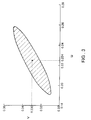
- FIG. 3 is a diagram showing a chromatic range of colors of light sources that provide easy recognition of red color according to the CIE 1960 UCS diagram.
- FIG. 4 is a diagram showing a chromatic range of colors of light sources that provide easy recognition of blue color according to the CIE 1960 UCS diagram.
- FIG. 5 is a diagram showing a chromatic range of colors of light sources that provide easy recognition of green color according to the CIE 1960 UCS diagram.
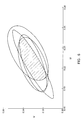
- FIG. 6 is a diagram showing a chromatic range of colors of light sources that provide easy recognition of colors in all the categories according to the CIE 1960 UCS diagram.
- FIG. 7 is a diagram showing a chromatic range of colors of light sources that provide high perception of white color according to the CIE 1960 UCS diagram.
- FIG. 8 is a graph showing the relationship between the correlated color temperature of light sources and the luminance of dazzling light sources.
- FIG. 9 is a graph showing the relationship between the correlated color temperature of light sources and the sense of incongruity caused by the difference from the color of light emitted from an incandescent lamp.
- FIG. 10 is a view showing an example of a luminaire of an embodiment of the present invention.
- FIG. 11 is a diagram showing the color points of light emitted from fluorescent lamps produced as examples of the present invention together with the evaluation results.
- observers viewed an achromatic color chart having a Munsel value of 9 under lamps having light sources radiating different emission colors, and judged how much chromatic color and how much white color they perceived the color of the color chart to contain, and answered their perception by giving points out of 100 points in proportion to the ratio of the chromatic color and white color.
- a hatched region in the CIE 1960 UCS diagram in FIG. 7 is shown as a region that can provide high perception of white color. For colors in the hatched region, the observers gave 90 points or more to white color.
- Glare of a light source Another problem is glare of a light source. Glaring light not only causes discomfort to the eyes, but also interferes with accurate perception of the surroundings. The glare of a light source was also examined.
- the observers judged the luminance that dazzles them when viewing light sources having different correlated color temperatures.
- the results are shown in FIG. 8.
- the graph shown in FIG. 8 indicates that as the correlated color temperature (K) became higher, the luminance that dazzles the observers became lower.
- the observers evaluated a sense of incongruity due to the difference in color between a tungsten halogen lamp with a color temperature of 2800 K and a fluorescent lamp when the lamps were illuminated simultaneously.
- the light source has a low color temperature, provides excellent color discrimination and high perception of white color, and causes low levels of glare and sense of incongruity due to the difference in colors when used with an incandescent lamp.
- the region within this circle is most preferable.
- chromatic ranges 1 encompass colors that provide excellent color discrimination.
- a chromatic range 2 encompasses colors that provide excellent perception of white color.
- a line 3 is an isotemperature line of a correlated color temperature of 3500 K, which is a boundary below which the illumination is not overly dazzling.
- a line 4 is an isotemperature line of a correlated color temperature of 3400 K, which is a boundary below which the difference in emission colors of the light sources barely causes the sense of incongruity when used with an incandescent lamp.
- the light source with a low color temperature whose color lies in a range common to the range for excellent color discrimination and the range for excellent perception of white color of the present invention has a low color temperature and provides excellent color discrimination and perception of white color. Furthermore, since the color point of the above-described light source lies in a range on the side of color temperatures lower than the isotemperature line of a correlated color temperature of 3500K, the light is not overly dazzling, in addition to providing excellent color discrimination and perception of white color.
- the color point of the above-described light source lies in a range on the side of color temperatures lower than the isotemperature line of a correlated color temperature of 3400K, the light is not overly dazzling, and the sense of incongruity is barely caused due to the difference in colors from the light sources when used with an incandescent lamp, in addition to providing excellent color discrimination and perception of white color.
- a discharge lamp radiates at least the following visible lights combined: light having an emission peak at a 400 to 490nm in a blue spectral region; light having an emission peak at 500 to 550nm in a green spectral region; and light having an emission peak at 600 to 670nm in a red spectral region.
- the discharge lamp can provide the advantages of the present invention by suitably selecting the radiation amount of lights in 400 to 490nm, 500 to 550nm and 600 to 670nm wavelength ranges.
- Radiation from atoms or molecules exited by radiation or discharge from a phosphor can be utilized to radiate the above-described visible lights.
- the above object can be achieved by providing the fluorescent lamp with a fluorescent layer including at least three phosphors having emission peaks in 400 to 490nm, 500 to 550nm and 600 to 670nm wavelength ranges as main components.
- the above object can be achieved by providing the fluorescent lamp with a fluorescent layer including at least four phosphors having emission peaks in 400 to 490nm, 500 to 535nm, 540 to 550nm and 600 to 670nm wavelength ranges as main components.
- a green phosphor with an emission peak at 500 to 535nm, or a red or dark red phosphor with an emission peak at 620 to 670nm may allow the colors of various colored objects to look vivid.
- the present invention can be provided with this effect as well.
- Examples of the phosphors that can be used when the discharge lamp is a fluorescent lamp are as follows: a bivalent europium activated blue phosphor as a phosphor with an emission peak in a 400 to 490nm wavelength range; bivalent manganese activated, trivalent terbium activated, trivalent terbium and trivalent cerium activated, and bivalent manganese and trivalent terbium activated green phosphors as a phosphor with an emission peak in a 500 to 550nm wavelength range; and trivalent europium activated, bivalent manganese activated, and tetravalent manganese activated red phosphor as a phosphor with an emission peak in a 600 to 670nm wavelength range.
- the above object can be achieved by using a bivalent manganese activated or bivalent manganese and bivalent europium activated green phosphor, which is a phosphor having an emission peak in a 500 to 535nm wavelength range, along with the above-described phosphors.
- Table 1 is a list showing phosphor materials that can be used to achieve the present invention.
- the object of the present invention of improving reproduction of colors of various colored objects illuminated can be achieved by using a luminaire having at least one of a transmitting plate and a reflecting plate that allow light from a light source to have suitable chromaticity.
- FIG. 10 shows an example of a luminaire of one embodiment of the present invention.
- This luminaire includes a luminaire housing 6, a lamp 7 provided in the housing 6, and a transmitting plate 8 provided in a light release port. Light from the lamp 7 passes through the transmitting plate 8, and the transmitted light 9 is utilized as illumination light.
- the transmitting plate 8 is designed to release light that has chromaticity in a range that can provide the advantages of the present invention.
- the transmitting plate 8 generally can be produced with glass or plastics, and the spectral transmittance in a visible light range of the transmitting plate 8 is controlled and designed so that an emission spectrum of light radiated from the lamp 7 can result in a desired illumination light that has the advantages of the present invention.
- a substance or substances that absorb light in a specific wavelength range are added to a material for the transmitting plate 8.
- the material is doped with metal ions that exclusively absorb light in a specific wavelength range as one component of the glass composition.
- the transmitting plate 8 is formed of plastic, it is known to mix a pigment that absorbs light in a specific wavelength range with the plastic before the plastic is molded into a plate, and then to mold the material including the pigment into a plate.
- either surface of a transparent or semi-transparent glass or plastic plate may be coated with a pigment or the like.
- the transmitting plate 8 can be produced by attaching a plastic film having a controlled spectral transmittance to either surface of the glass or plastic plate.
- the example shown in FIG. 10 is a luminaire having a transmitting plate, but it is possible to use a luminaire having a housing provided with a reflecting plate that reflects light in a chromaticity range that provides the advantages of the present invention. Furthermore, the luminaire may include both a transmitting plate and a reflecting plate.
- illumination light that provides easy color discrimination (identification) of an object illuminated by light with a low color temperature and barely causes glare can be obtained by using a luminaire including at least one of a transmitting plate and a reflecting plate for radiating the following illumination light.
- the illumination light includes at least the following lights combined: light having an emission peak in 400 to 490 nm wavelength range in a blue spectral region; light having an emission peak in a 500 to 550 nm wavelength range in a green spectral region; and light having with an emission peak in 600 to 670 nm wavelength range in a red spectral region.
- illumination light with a low color temperature that provides excellent perception of white color and barely causes glare can be obtained by using a luminaire including at least one of a transmitting plate and a reflecting plate for radiating the following illumination light.
- the illumination light includes at least the following lights combined: light having an emission peak in 400 to 490 nm wavelength range in a blue spectral region; light having an emission peak in a 500 to 550 nm wavelength range in a green spectral region; and light having with an emission peak in 600 to 670 nm wavelength range in a red spectral region.
- the illumination light radiated from the luminaire of the present invention has a color point in a region on a side of color temperature lower than an isotemperature line of a correlated color temperature of 3500K, the illumination light barely causes glare, in addition to the above-described advantages. Furthermore, when the illumination light radiated from the luminaire of the present invention has a color point in a region on a side of color temperature lower than an isotemperature line of a correlated color temperature of 3400K, the illumination light barely causes a sense of incongruity due to the difference in colors of the light sources when used with an incandescent lamp, in addition to the above-described advantages.
- Table 2 shows lamp numbers, the types of phosphors and the weight ratio thereof, the color points in the CIE 1960 UCS diagram of the lamps, the correlated color temperature Tc of the lamps, the chromaticity deviation Auv from the Planckian locus in the CIE 1960 UCS diagram of the lamps ("+” indicates a chromaticity deviation toward the upper left side from the Planckian locus in the CIE 1960 UCS diagram, and " -" indicates a chromaticity deviation toward the lower right side from the Planckian locus), the evaluation results of ease of color discrimination, perception of white color, glare of the light sources, a sense of incongruity with respect to an electric lamp, and comprehensive evaluation as to whether or not the lamp can create a suitable illumination environment, focusing on natural reproduction of colors.
- FIG. 11 is a CIE 1960 UCS diagram showing the color points of emission colors of the produced and evaluated lamps shown in Table 2 together with enlarged preferable chromaticity ranges obtained from the experiments described above.
- the color points of the lamps are shown by o ⁇ , ⁇ , ⁇ , and ⁇ , which are the evaluation results as to whether or not the lamp can create a suitable illumination environment, focusing on natural reproduction of colors, shown in Table 2.
- the letters in FIG. 11 identify the lamps shown in Table 2.
Landscapes
- Vessels And Coating Films For Discharge Lamps (AREA)
- Non-Portable Lighting Devices Or Systems Thereof (AREA)
Abstract
Description
- The present invention relates to a discharge lamp and a luminaire.
- Currently, colors reproduced by a variety of light sources are evaluated quantitatively based on the color rendering index, which has been an established method for quantitative evaluation of colors. The color rendering index evaluates quantitatively how faithfully light of interest reproduces colors, compared with a reference light. Recently, however, more attention has been paid to how desirably colors are reproduced, apart from the faithful reproduction. It has become increasingly important to illuminate colors in our living space such as colors of human skin, food, plants, interior decorations and clothes desirably.
- At the present, discharge lamps for general illumination having a relatively high correlated color temperature ranging from about 5000K to about 7000K are commonly used for main illumination in houses and stores. However, it is said that lamps with a low color temperature from about 2800 to 4500K are more suitable to create a relaxed atmosphere in the illuminated space than lamps with a high color temperature. For this reason, a light source with a low color temperature is gaining its popularity gradually year by year in the field of illumination in houses and stores.
- Furthermore, a lamp with a high color temperature is more dazzling than a lamp with a low color temperature when the light source is viewed directly. Moreover, an incandescent lamp for downlight tends to be used together with a lamp for main illumination as a recent approach for illumination in houses and stores. When a lamp with a high color temperature is used for main illumination and an incandescent lamp is used additionally, the difference in color between the lamp with a high color temperature and the incandescent lamp causes a sense of incongruity.
- As described above, although lamps with a low color temperature are thought to be suitable to create a relaxed atmosphere, lamps in a conventional low color temperature range of about 3700K or less are believed to pose a problem as to how colors look under the lamps. For example, such a lamp allows an object illuminated such as a new tatami mat to look yellowish like an old mat, or the skin of a Japanese person to look unnatural, even though the lamp has a high color rendering index so that it can reproduce colors faithfully and emits three lights of blue, green and red as main emission. Thus, the color of the object illuminated is not reproduced desirably. Furthermore, there is another problem in that a white object such as a paper or a white shirt does not look white, namely, the lamp cannot provide high perception of white. It is also said that a lamp in a conventional low temperature range cannot provide sufficient color identification because natural colors are not reproduced, and it is more difficult to distinguish similar colors under such a lamp.
- Therefore, with the foregoing in mind, it is the object of the present invention to provide a discharge lamp and a luminaire primarily emitting combined lights in blue, green and red spectral regions that allows improved reproduction of natural colors of various colored objects, is not overly dazzling, and barely causes a sense of incongruity when used with an incandescent lamp.
- In order to solve the above-described problems, a first discharge lamp of the present invention radiates visible light including the following lights combined: light having an emission peak in 400 to 490 nm wavelength range in a blue spectral region; light having an emission peak in a 500 to 550 nm wavelength range in a green spectral region; and light having with an emission peak in 600 to 670 nm wavelength range in a red spectral region. The color point of the combined light lies within a region common to the following regions: a region bounded by an ellipse with a color point (u, v) = (0.224, 0.330) as its center, a major axis of 0.056, a minor axis of 0.024, and an angle from the u axis of 20 degrees in the CIE 1960 UCS diagram; a region bounded by an ellipse with a color point (u, v) = (0.224, 0.330) as its center, a major axis of 0.078, a minor axis of 0.014, and an angle from the u axis of 30 degrees in the CIE 1960 UCS diagram; a region bounded by an ellipse with a color point (u, v) = (0.235, 0.335) as its center, a major axis of 0.060, a minor axis of 0.030, and an angle from the u axis of 30 degrees in the CIE 1960 UCS diagram; a region bounded by an ellipse with a color point (u, v) = (0.225, 0.330) as its center, a major axis of 0.060, a minor axis of 0.018, and an angle from the u axis of 20 degrees in the CIE 1960 UCS diagram; and a region on a side of color temperature lower than an isotemperature line of a correlated color temperature of 3500K.
- This embodiment achieves a discharge lamp with a low color temperature primarily radiating combined lights in blue, green and red spectral regions that provides excellent color discrimination (identification) and is not overly dazzling.
- The visible light radiated by this discharge lamp includes radiation of atoms or molecules exited by radiation or discharge from a phosphor.
- A second discharge lamp of the present invention radiates visible light including the following lights combined: light having an emission peak in 400 to 490 nm wavelength range in a blue spectral region; light having an emission peak in a 500 to 550 nm wavelength range in a green spectral region; and light having with an emission peak in 600 to 670 nm wavelength range in a red spectral region. The color point of the combined light lies within a region bounded by lines connecting four color points (u, v) = (0.235, 0.342), (0.252, 0.345), (0.248, 0.338), and (0.239, 0.334) in the CIE 1960 UCS diagram.
- This embodiment achieves a discharge lamp with a low color temperature primarily radiating combined lights in blue, green and red spectral regions that allows an illuminated white object to be perceived as white (i.e., provides excellent perception of white) and is not overly dazzling.
- A third discharge lamp of the present invention radiates visible light including the following lights combined: light having an emission peak in 400 to 490 nm wavelength range in a blue spectral region; light having an emission peak in a 500 to 550 nm wavelength range in a green spectral region; and light having with an emission peak in 600 to 670 nm wavelength range in a red spectral region. The color point of the combined light lies within a region common to the following regions: a region bounded by an ellipse with a color point (u, v) = (0.224, 0.330) as its center, a major axis of 0.056, a minor axis of 0.024, and an angle from the u axis of 20 degrees in the CIE 1960 UCS diagram; a region bounded by an ellipse with a color point (u, v) = (0.224, 0.330) as its center, a major axis of 0.078, a minor axis of 0.014, and an angle from the u axis of 30 degrees in the CIE 1960 UCS diagram; a region bounded by an ellipse with a color point (u, v) = (0.235, 0.335) as its center, a major axis of 0.060, a minor axis of 0.030, and an angle from the u axis of 30 degrees in the CIE 1960 UCS diagram; a region bounded by an ellipse with a color point (u, v) = (0.225, 0.330) as its center, a major axis of 0.060, a minor axis of 0.018, and an angle from the u axis of 20 degrees in the CIE 1960 UCS diagram; and a region bounded by lines connecting four color points: (u, v) = (0.235, 0.342), (0.252, 0.345), (0.248, 0.338), and (0.239, 0.334) in the CIE 1960 UCS diagram.
- This embodiment achieves a discharge lamp that has both of the advantages of the first and second discharge lamps.
- In the first, second and third discharge lamps, the color point of the combined light preferably lies within a region on a side of color temperature lower than an isotemperature line of a correlated color temperature of 3400K in the CIE 1960 UCS diagram.
- This embodiment provides an advantage in that when the discharge lamp is used with an incandescent lamp, a sense of incongruity is barely caused by the difference in colors of lights emitted from the light sources, in addition to the advantages provided by the first, second or third discharge lamp.
- In the first, second and third discharge lamps, the color point of the combined light preferably lies within a circle having a center thereof at a color point (u, v) = (0.2457, 0.3403) and a radius of 0.003 in the CIE 1960 UCS diagram.
- This embodiment ensures the advantages of providing excellent discrimination and perception of white, low levels of glare, and low levels of a sense of incongruity when the discharge lamp is used with an incandescent lamp.
- A fourth discharge lamp having the characteristics of the first, second, or third discharge lamp is a fluorescent lamp. The fluorescent lamp includes a fluorescent layer including three phosphors having emission peaks in 400 to 490nm, 500 to 550nm, and 600 to 670 nm wavelength ranges as main components.
- This embodiment achieves a discharge lamp with a low color temperature primarily radiating combined lights in blue, green and red spectral regions that provides excellent color discrimination and perception of white, and is not overly dazzling.
- In the fourth discharge lamp, the fluorescent layer preferably includes the following three phosphors as main components: at least one bivalent europium activated blue phosphor having an emission peak in a 400 to 490nm wavelength range; at least one phosphor selected from the group consisting of bivalent manganese activated, trivalent terbium activated, trivalent terbium and trivalent cerium activated, and bivalent manganese and trivalent terbium activated green phosphors having an emission peak in a 500 to 550nm wavelength range; and at least one phosphor selected from the group consisting of trivalent europium activated, bivalent manganese activated, and tetravalent manganese activated red phosphors having an emission peak in a 600 to 670nm wavelength range.
- This embodiment achieves a discharge lamp with a low color temperature primarily radiating combined lights in blue, green and red spectral regions that provides excellent color discrimination or perception of white, and is not overly dazzling.
- A fifth discharge lamp having the characteristics of the first, second, or third discharge lamp is a fluorescent lamp. The fluorescent lamp includes a fluorescent layer including four phosphors having emission peaks in 400 to 490nm, 500 to 535nm, 540 to 550 nm, and 600 to 670nm wavelength ranges as main components.
- This embodiment achieves a discharge lamp with a low color temperature primarily radiating combined lights in blue, green and red spectral regions that provides excellent color discrimination or perception of white, and is not overly dazzling.
- In the fifth discharge lamp, the fluorescent layer preferably includes the following four phosphors as main components: at least one bivalent europium activated blue phosphor having an emission peak in a 400 to 490nm wavelength range; at least one phosphor selected from the group consisting of bivalent manganese activated, and bivalent manganese and bivalent europium activated green phosphors having an emission peak in a 500 to 535nm wavelength range; at least one phosphor selected from the group consisting of trivalent terbium activated, trivalent terbium and trivalent cerium activated, and bivalent manganese and trivalent terbium activated green phosphors having an emission peak in a 540 to 550nm wavelength range; and at least one phosphor selected from the group consisting of trivalent europium activated, bivalent manganese activated, and tetravalent manganese activated red phosphors having an emission peak in a 600 to 670nm wavelength range.
- This embodiment achieves a discharge lamp with a low color temperature primarily radiating combined lights in blue, green and red spectral regions that provides excellent color discrimination or perception of white and is not overly dazzling.
- A first luminaire includes at least one selected from the group consisting of a transmitting plate and a reflecting plate for radiating illumination light including the following lights combined: light having an emission peak in 400 to 490 nm wavelength range in a blue spectral region; light having an emission peak in a 500 to 550 nm wavelength range in a green spectral region; and light having with an emission peak in 600 to 670 nm wavelength range in a red spectral region. The color point of the illumination light lies within a region common to the following regions: a region bounded by an ellipse with a color point (u, v) = (0.224, 0.330) as its center, a major axis of 0.056, a minor axis of 0.024, and an angle from the u axis of 20 degrees in the CIE 1960 UCS diagram; a region bounded by an ellipse with a color point (u, v) = (0.224, 0.330) as its center, a major axis of 0.078, a minor axis of 0.014, and an angle from the u axis of 30 degrees in the CIE 1960 UCS diagram; a region bounded by an ellipse with a color point (u, v) = (0.235, 0.335) as its center, a major axis of 0.060, a minor axis of 0.030, and an angle from the u axis of 30 degrees in the CIE 1960 UCS diagram; a region bounded by an ellipse with a color point (u, v) = (0.225, 0.330) as its center, a major axis of 0.060, a minor axis of 0.018, and an angle from the u axis of 20 degrees in the CIE 1960 UCS diagram; and a region on a side of color temperature lower than an isotemperature line of a correlated color temperature of 3500K.
- In this embodiment, the illumination light that has transmitted the transmitting plate or reflected from the reflecting plate primarily consists of lights in blue, green and red spectral regions and has a low color temperature, and the luminaire provides excellent color discrimination (identification) and is not overly dazzling.
- A second luminaire includes at least one selected from the group consisting of a transmitting plate and a reflecting plate for radiating illumination light including the following lights combined: light having an emission peak in 400 to 490 nm wavelength range in a blue spectral region; light having an emission peak in a 500 to 550 nm wavelength range in a green spectral region; and light having with an emission peak in 600 to 670 nm wavelength range in a red spectral region. The color point of the illumination light lies within a region bounded by lines connecting four color points (u, v) = (0.235, 0.342), (0.252, 0.345), (0.248, 0.338), and (0.239, 0.334) in the CIE 1960 UCS diagram.
- In this embodiment, the illumination light that has transmitted the transmitting plate or reflected from the reflecting plate primarily consists of lights in blue, green and red spectral regions and has a low color temperature, and the luminaire provides excellent perception of white and is not overly dazzling.
- A third luminaire includes at least one selected from the group consisting of a transmitting plate and a reflecting plate for radiating illumination light comprising the following lights combined: light having an emission peak in 400 to 490 nm wavelength range in a blue spectral region; light having an emission peak in a 500 to 550 nm wavelength range in a green spectral region; and light having with an emission peak in 600 to 670 nm wavelength range in a red spectral region. The color point of the illumination light lies within a region common to the following regions: a region bounded by an ellipse with a color point (u, v) = (0.224, 0.330) as its center, a major axis of 0.056, a minor axis of 0.024, and an angle from the u axis of 20 degrees in the CIE 1960 UCS diagram; a region bounded by an ellipse with a color point (u, v) = (0.224, 0.330) as its center, a major axis of 0.078, a minor axis of 0.014, and an angle from the u axis of 30 degrees in the CIE 1960 UCS diagram; a region bounded by an ellipse with a color point (u, v) = (0.235, 0.335) as its center, a major axis of 0.060, a minor axis of 0.030, and an angle from the u axis of 30 degrees in the CIE 1960 UCS diagram; a region bounded by an ellipse with a color point (u, v) = (0.225, 0.330) as its center, a major axis of 0.060, a minor axis of 0.018, and an angle from the u axis of 20 degrees in the CIE 1960 UCS diagram; and a region bounded by lines connecting four color points: (u, v) = (0.235, 0.342), (0.252, 0.345), (0.248, 0.338), and (0.239, 0.334) in the CIE 1960 UCS diagram.
- This embodiment achieves a luminaire that has both of the advantages of the first and second luminaires.
- In the first, second and third luminaires, the color point of the illumination light preferably lies within a region on a side of color temperature lower than an isotemperature line of a correlated color temperature of 3400K in the CIE 1960 UCS diagram.
- This embodiment provides an advantage in that the illumination light that has transmitted the transmitting plate or reflected from the reflecting plate is not overly dazzling, and a sense of incongruity is barely caused by the difference in colors of lights emitted from the light sources when the luminaire is used with an incandescent lamp, in addition to the advantage of excellent color discrimination or perception of white.
- In the first, second and third luminaire, the color point of the illumination light lies within a circle having a center thereof at a color point (u, v) = (0.2457, 0.3403) and a radius of 0.003 in the CIE 1960 UCS diagram.
- This embodiment achieves a luminaire radiating illumination light that is ensured to have the advantages of providing excellent discrimination and perception of white, low levels of glare and low levels of sense of incongruity when the luminaire is used with an incandescent lamp.
- These and other advantages of the present invention will become apparent to those skilled in the art upon reading and understanding the following detailed description with reference to the accompanying figures.
- FIG. 1 is a diagram collectively showing chromatic ranges of emission colors that provide the advantages of the present invention (i.e., excellent color discrimination, high perception of white color, low levels of glare caused by illumination, and low levels of a sense of incongruity due to the difference in colors of lights emitted from the light sources when used with an incandescent lamp) and an especially preferable range, according to the CIE 1960 UCS diagram.
- FIG. 2 is a diagram showing a chromatic range of colors of light sources that provide easy discrimination between black and dark blue colors according to the CIE 1960 UCS diagram.
- FIG. 3 is a diagram showing a chromatic range of colors of light sources that provide easy recognition of red color according to the CIE 1960 UCS diagram.
- FIG. 4 is a diagram showing a chromatic range of colors of light sources that provide easy recognition of blue color according to the CIE 1960 UCS diagram.
- FIG. 5 is a diagram showing a chromatic range of colors of light sources that provide easy recognition of green color according to the CIE 1960 UCS diagram.
- FIG. 6 is a diagram showing a chromatic range of colors of light sources that provide easy recognition of colors in all the categories according to the CIE 1960 UCS diagram.
- FIG. 7 is a diagram showing a chromatic range of colors of light sources that provide high perception of white color according to the CIE 1960 UCS diagram.
- FIG. 8 is a graph showing the relationship between the correlated color temperature of light sources and the luminance of dazzling light sources.
- FIG. 9 is a graph showing the relationship between the correlated color temperature of light sources and the sense of incongruity caused by the difference from the color of light emitted from an incandescent lamp.
- FIG. 10 is a view showing an example of a luminaire of an embodiment of the present invention.
- FIG. 11 is a diagram showing the color points of light emitted from fluorescent lamps produced as examples of the present invention together with the evaluation results.
- Hereinafter, experiments for obtaining chromatic ranges in which light from a light source having a low color temperature allows desirable reproduction of the color of a colored object will be described with reference to the accompanying drawings.
- First, experiments were conducted to study color discrimination (identification) for the colors often used in a house under various lamps having different colors of light emitted from the light sources. In the experiments, it was determined how easily observers were able to discern colors typically used in a house, i.e., black and dark blue, red, blue, and green. The observers judged a difference in colors of color charts for a target color by varying the color difference of the color.
- FIG. 2 shows the experimental results regarding the ease of discernment of black and dark blue colors. It was found that when the color point of a light source lies within a region bounded by an ellipse with a color point (u, v) = (0.224, 0.330) as its center, a major axis of 0.056, a minor axis of 0.024, and an angle from the u axis of 20 degrees in the CIE 1960 UCS diagram, 75% or more of the observers were able to discern colors whose color difference is at least 2 in the CIE 1976 L*a*b* color space.
- FIG. 3 shows the experimental results regarding the ease of discernment of red color. It was found that when the color point of the emission color of a light source lies within a region bounded by an ellipse with a color point (u, v) = (0.224, 0.330) as its center, a major axis of 0.078, a minor axis of 0.014, and an angle from the u axis of 30 degrees in the CIE 1960 UCS diagram, 75% or more of the observers were able to discern colors whose color difference is at least 2 in the CIE 1976 L*a*b* color space.
- FIG. 4 shows the experimental results regarding the ease of discernment of blue color. It was found that when the color point of emission color of a light source lies within a region bounded by an ellipse with a color point (u, v) = (0.235, 0.335) as its center, a major axis of 0.060, a minor axis of 0.030, and an angle from the u axis of 30 degrees in the CIE 1960 UCS diagram, 75% or more of the observers were able to discern colors whose color difference is at least 2 in the CIE 1976 L*a*b* color space.
- FIG. 5 shows the experimental results regarding the ease of discernment of green color. It was found that when the color point of emission color of a light source lies within a region bounded by an ellipse with a color point (u, v) = (0.225, 0.330) as its center, a major axis of 0.060, a minor axis of 0.018, and an angle from the u axis of 20 degrees in the CIE 1960 UCS diagram, 75% or more of the observers were able to discern colors whose color difference is at least 2 in the CIE 1976 L*a*b* color space.
- In other words, it can be concluded that when a light source emitting light whose color point lies within a region common to all the regions bounded by the four ellipses with respect to ease of discernment of black and dark blue, red, blue, and green colors obtained by the experiments, excellent color discrimination can be achieved for colors in substantially all the categories. The range common to all the regions bounded by the four ellipses is shown as a hatched region in FIG. 6.
- Next, experiments were conducted regarding the perception of white color when observing an object of an achromatic color illuminated by various lamps having different light source colors that have a low correlated color temperature of 3500K or less.
- In the experiments, observers viewed an achromatic color chart having a Munsel value of 9 under lamps having light sources radiating different emission colors, and judged how much chromatic color and how much white color they perceived the color of the color chart to contain, and answered their perception by giving points out of 100 points in proportion to the ratio of the chromatic color and white color. A hatched region in the CIE 1960 UCS diagram in FIG. 7 is shown as a region that can provide high perception of white color. For colors in the hatched region, the observers gave 90 points or more to white color. The region is bounded by lines connecting four color points (u, v) = (0.235, 0.342), (0.252, 0.345), (0.248, 0.338), and (0.239, 0.334) in the CIE 1960 UCS diagram. Thus, it was found that light sources whose emission colors lie in this region permit a white object to be recognized as being white.
- Furthermore, with respect to colors of light in a low color temperature range of 3500K or less, perception of white color was compared between colors having the same correlated color temperature. As a result, it was found that among the light sources whose colors lie in the region bounded by lines connecting four color points (u, v) = (0.235, 0.342), (0.252, 0.345), (0.248, 0.338), and (0.239, 0.334) in the CIE 1960 UCS diagram, the light sources whose colors have a chromaticity deviation of -0.007 to -0.003 from the Planckian locus in the CIE 1960 UCS diagram (" -" indicates a chromaticity deviation toward the lower right side from the Planckian locus in the CIE 1960 UCS diagram) provide especially high perception of white color.
- Another problem is glare of a light source. Glaring light not only causes discomfort to the eyes, but also interferes with accurate perception of the surroundings. The glare of a light source was also examined.
- Experiments were conducted to study how much glare is caused by a light source by varying the correlated color temperature of emission color of a light source. In the experiments, the observers identified the same luminance as dazzling when viewing a light source having 3000 K.
- Assuming the luminance of the light source with 3000 K as 1, the observers judged the luminance that dazzles them when viewing light sources having different correlated color temperatures. The results are shown in FIG. 8. The graph shown in FIG. 8 indicates that as the correlated color temperature (K) became higher, the luminance that dazzles the observers became lower.
- As a result of further analysis, it was found that there is no significant difference in a significant level of 5% between the luminance that dazzled the observers when viewing a light source with a correlated temperature of 3500 K or less and the luminance that dazzled the observers when viewing a light source with a correlated temperature of 3000 K. More specifically, it was found that the light source with a correlated temperature of 3500 K or less causes substantially the same level of glare as that caused by the light source with a correlated temperature of 3000 K.
- Next, the observers evaluated a sense of incongruity due to the difference in color between a tungsten halogen lamp with a color temperature of 2800 K and a fluorescent lamp when the lamps were illuminated simultaneously.
- The sense of incongruity due to the difference in colors was evaluated by a method in which the observers selected one out of the following 5 categories: the difference in colors is "significantly bothering", "bothering", "acceptable", "not bothering", and "not bothering at all". The results are shown in FIG. 9. These results confirmed that as the correlated color temperature of the fluorescent lamp became higher, the difference in colors became more bothering. Thus, it was confirmed that the difference in colors is acceptable when the correlated color temperature of the fluorescent lamp is 3400K or less.
- As a result of comprehensive evaluation of the results of the visibility evaluation tests described above, it was found that when the color point of the emission color of a light source is within a circle having its center at a color point (u, v) = (0.2457, 0.3403) and a radius of 0.003 in the CIE 1960 UCS diagram, the light source has a low color temperature, provides excellent color discrimination and high perception of white color, and causes low levels of glare and sense of incongruity due to the difference in colors when used with an incandescent lamp. The region within this circle is most preferable.
- The chromatic ranges having the advantages of the present invention are collectively shown in the CIE 1960 UCS diagram in FIG. 1. In FIG. 1,
chromatic ranges 1 encompass colors that provide excellent color discrimination. Achromatic range 2 encompasses colors that provide excellent perception of white color. A line 3 is an isotemperature line of a correlated color temperature of 3500 K, which is a boundary below which the illumination is not overly dazzling. A line 4 is an isotemperature line of a correlated color temperature of 3400 K, which is a boundary below which the difference in emission colors of the light sources barely causes the sense of incongruity when used with an incandescent lamp. Acircle 5 is a most preferably region, which is a circle having its center at a color point (u, v) = (0.2457, 0.3403) and a radius of 0.003 in the CIE 1960 UCS diagram. - The light source with a low color temperature whose color lies in a range common to the range for excellent color discrimination and the range for excellent perception of white color of the present invention has a low color temperature and provides excellent color discrimination and perception of white color. Furthermore, since the color point of the above-described light source lies in a range on the side of color temperatures lower than the isotemperature line of a correlated color temperature of 3500K, the light is not overly dazzling, in addition to providing excellent color discrimination and perception of white color. When the color point of the above-described light source lies in a range on the side of color temperatures lower than the isotemperature line of a correlated color temperature of 3400K, the light is not overly dazzling, and the sense of incongruity is barely caused due to the difference in colors from the light sources when used with an incandescent lamp, in addition to providing excellent color discrimination and perception of white color.
- In order to achieve the light source having the above-described advantages, a discharge lamp radiates at least the following visible lights combined: light having an emission peak at a 400 to 490nm in a blue spectral region; light having an emission peak at 500 to 550nm in a green spectral region; and light having an emission peak at 600 to 670nm in a red spectral region. The discharge lamp can provide the advantages of the present invention by suitably selecting the radiation amount of lights in 400 to 490nm, 500 to 550nm and 600 to 670nm wavelength ranges.
- Radiation from atoms or molecules exited by radiation or discharge from a phosphor can be utilized to radiate the above-described visible lights.
- When the discharge lamp is a fluorescent lamp, the above object can be achieved by providing the fluorescent lamp with a fluorescent layer including at least three phosphors having emission peaks in 400 to 490nm, 500 to 550nm and 600 to 670nm wavelength ranges as main components.
- Similarly, the above object can be achieved by providing the fluorescent lamp with a fluorescent layer including at least four phosphors having emission peaks in 400 to 490nm, 500 to 535nm, 540 to 550nm and 600 to 670nm wavelength ranges as main components.
- It is well known that a green phosphor with an emission peak at 500 to 535nm, or a red or dark red phosphor with an emission peak at 620 to 670nm may allow the colors of various colored objects to look vivid. The present invention can be provided with this effect as well.
- Examples of the phosphors that can be used when the discharge lamp is a fluorescent lamp are as follows: a bivalent europium activated blue phosphor as a phosphor with an emission peak in a 400 to 490nm wavelength range; bivalent manganese activated, trivalent terbium activated, trivalent terbium and trivalent cerium activated, and bivalent manganese and trivalent terbium activated green phosphors as a phosphor with an emission peak in a 500 to 550nm wavelength range; and trivalent europium activated, bivalent manganese activated, and tetravalent manganese activated red phosphor as a phosphor with an emission peak in a 600 to 670nm wavelength range.
- Furthermore, the above object can be achieved by using a bivalent manganese activated or bivalent manganese and bivalent europium activated green phosphor, which is a phosphor having an emission peak in a 500 to 535nm wavelength range, along with the above-described phosphors. Table 1 is a list showing phosphor materials that can be used to achieve the present invention.
Phosphor Abbrevia tion Peak wavelength Emission color europium activated strontium phosphate SPE 434nm blue europium activated barium magnesium aluminate BAM 450nm blue europium activated strontium chloroapatite SCA 450nm blue europium activated strontium aluminate SAE 490nm bluish green europium and manganese activated barium magnesium aluminate BAM-Mn 515nm green manganese activated cerium magnesium aluminate CMM 518nm green manganese activated zinc silicate ZSM 525nm green terbium activated cerium magnesium aluminate CAT 545nm green cerium and terbium activated lanthanum phosphate LAP 545nm green terbium and manganese activated cerium magnesium aluminate CAM 545nm 518nm green europium activated yttrium oxide YOX 611nm red europium activated yttrium phosphate vanadate PW 621nm red europium activated yttrium oxysulfide YOS 627nm red manganese activated cerium gadolinium borate CBM 628nm red manganese activated fluoromagnesium germanate MFG 658nm dark red - The object of the present invention of improving reproduction of colors of various colored objects illuminated can be achieved by using a luminaire having at least one of a transmitting plate and a reflecting plate that allow light from a light source to have suitable chromaticity. FIG. 10 shows an example of a luminaire of one embodiment of the present invention.
- This luminaire includes a
luminaire housing 6, alamp 7 provided in thehousing 6, and a transmittingplate 8 provided in a light release port. Light from thelamp 7 passes through the transmittingplate 8, and the transmittedlight 9 is utilized as illumination light. The transmittingplate 8 is designed to release light that has chromaticity in a range that can provide the advantages of the present invention. - More specifically, the transmitting
plate 8 generally can be produced with glass or plastics, and the spectral transmittance in a visible light range of the transmittingplate 8 is controlled and designed so that an emission spectrum of light radiated from thelamp 7 can result in a desired illumination light that has the advantages of the present invention. - In order to control the spectral transmittance in a visible light range of the transmitting
plate 8, a substance or substances that absorb light in a specific wavelength range are added to a material for the transmittingplate 8. Typically, when the transmittingplate 8 is formed of glass, the material is doped with metal ions that exclusively absorb light in a specific wavelength range as one component of the glass composition. When the transmittingplate 8 is formed of plastic, it is known to mix a pigment that absorbs light in a specific wavelength range with the plastic before the plastic is molded into a plate, and then to mold the material including the pigment into a plate. - Furthermore, either surface of a transparent or semi-transparent glass or plastic plate may be coated with a pigment or the like. Alternatively, the transmitting
plate 8 can be produced by attaching a plastic film having a controlled spectral transmittance to either surface of the glass or plastic plate. - The example shown in FIG. 10 is a luminaire having a transmitting plate, but it is possible to use a luminaire having a housing provided with a reflecting plate that reflects light in a chromaticity range that provides the advantages of the present invention. Furthermore, the luminaire may include both a transmitting plate and a reflecting plate.
- More specifically, illumination light that provides easy color discrimination (identification) of an object illuminated by light with a low color temperature and barely causes glare can be obtained by using a luminaire including at least one of a transmitting plate and a reflecting plate for radiating the following illumination light. The illumination light includes at least the following lights combined: light having an emission peak in 400 to 490 nm wavelength range in a blue spectral region; light having an emission peak in a 500 to 550 nm wavelength range in a green spectral region; and light having with an emission peak in 600 to 670 nm wavelength range in a red spectral region. The color point of the illumination light lies within a region common to the following regions: a region bounded by an ellipse with a color point (u, v) = (0.224, 0.330) as its center, a major axis of 0.056, a minor axis of 0.024, and an angle from the u axis of 20 degrees in the CIE 1960 UCS diagram; a region bounded by an ellipse with a color point (u, v) = (0.224, 0.330) as its center, a major axis of 0.078, a minor axis of 0.014, and an angle from the u axis of 30 degrees in the CIE 1960 UCS diagram; a region bounded by an ellipse with a color point (u, v) = (0.235, 0.335) as its center, a major axis of 0.060, a minor axis of 0.030, and an angle from the u axis of 30 degrees in the CIE 1960 UCS diagram; a region bounded by an ellipse with a color point (u, v) = (0.225, 0.330) as its center, a major axis of 0.060, a minor axis of 0.018, and an angle from the u axis of 20 degrees in the CIE 1960 UCS diagram; and a region on a side of color temperature lower than an isotemperature line of a correlated color temperature of 3500K.
- Furthermore, illumination light with a low color temperature that provides excellent perception of white color and barely causes glare can be obtained by using a luminaire including at least one of a transmitting plate and a reflecting plate for radiating the following illumination light. The illumination light includes at least the following lights combined: light having an emission peak in 400 to 490 nm wavelength range in a blue spectral region; light having an emission peak in a 500 to 550 nm wavelength range in a green spectral region; and light having with an emission peak in 600 to 670 nm wavelength range in a red spectral region. The color point of the illumination light lies within a region bounded by lines connecting four color points: (u, v) = (0.235, 0.342), (0.252, 0.345), (0.248, 0.338), and (0.239, 0.334) in the CIE 1960 UCS diagram. In this case, among the light sources whose emission colors lie in the region bounded by lines connecting four color points (u, v) = (0.235, 0.342), (0.252, 0.345), (0.248, 0.338), and (0.239, 0.334) in the CIE 1960 UCS diagram, the light sources whose emission colors have a chromaticity deviation of 0.007 to -0.003 from the Planckian locus in the CIE 1960 UCS diagram provide especially high perception of white color.
- Illumination light provides easy color discrimination (identification) of an illuminated object and excellent perception of white color, when the following two requirements are satisfied: (1) the illumination light having transmitted the transmitting plate or reflected from the reflecting plate includes at least the following lights combined: light having an emission peak in 400 to 490 nm wavelength range in a blue spectral region; light having an emission peak in a 500 to 550 nm wavelength range in a green spectral region; and light having with an emission peak in 600 to 670 nm wavelength range in a red spectral region; and (2) the color point of the illumination light lies within a region common to the following regions: a region bounded by an ellipse with a color point (u, v) = (0.224, 0.330) as its center, a major axis of 0.056, a minor axis of 0.024, and an angle from the u axis of 20 degrees in the CIE 1960 UCS diagram; a region bounded by an ellipse with a color point (u, v) = (0.224, 0.330) as its center, a major axis of 0.078, a minor axis of 0.014, and an angle from the u axis of 30 degrees in the CIE 1960 UCS diagram; a region bounded by an ellipse with a color point (u, v) = (0.235, 0.335) as its center, a major axis of 0.060, a minor axis of 0.030, and an angle from the u axis of 30 degrees in the CIE 1960 UCS diagram; a region bounded by an ellipse with a color point (u, v) = (0.225, 0.330) as its center, a major axis of 0.060, a minor axis of 0.018, and an angle from the u axis of 20 degrees in the CIE 1960 UCS diagram; and a region bounded by lines connecting four color points: (u, v) = (0.235, 0.342), (0.252, 0.345), (0.248, 0.338), and (0.239, 0.334) in the CIE 1960 UCS diagram.
- Furthermore, since the illumination light radiated from the luminaire of the present invention has a color point in a region on a side of color temperature lower than an isotemperature line of a correlated color temperature of 3500K, the illumination light barely causes glare, in addition to the above-described advantages. Furthermore, when the illumination light radiated from the luminaire of the present invention has a color point in a region on a side of color temperature lower than an isotemperature line of a correlated color temperature of 3400K, the illumination light barely causes a sense of incongruity due to the difference in colors of the light sources when used with an incandescent lamp, in addition to the above-described advantages.
- When the color point of light having transmitted the transmitting plate or reflected from the reflecting plate is within a circle having its center at a color point (u, v) = (0.2457, 0.3403) and a radius of 0.003 in the CIE 1960 UCS diagram, the following advantages are provided: excellent color discrimination and perception of white color; low levels of glare; and low levels of a sense of incongruity due to the difference in colors when used with an incandescent lamp. The region within this circle is most preferable.
- Next, evaluation tests by actual observation were conducted with respect to fluorescent lamps produced with the phosphors listed in Table 1. Table 2 shows the results.

- Table 2 shows lamp numbers, the types of phosphors and the weight ratio thereof, the color points in the CIE 1960 UCS diagram of the lamps, the correlated color temperature Tc of the lamps, the chromaticity deviation Auv from the Planckian locus in the CIE 1960 UCS diagram of the lamps ("+" indicates a chromaticity deviation toward the upper left side from the Planckian locus in the CIE 1960 UCS diagram, and " -" indicates a chromaticity deviation toward the lower right side from the Planckian locus), the evaluation results of ease of color discrimination, perception of white color, glare of the light sources, a sense of incongruity with respect to an electric lamp, and comprehensive evaluation as to whether or not the lamp can create a suitable illumination environment, focusing on natural reproduction of colors.
- The evaluation results of ease of color discrimination, perception of white color, glare of the light sources, a sense of incongruity with respect to an electric lamp, and the comprehensive evaluation are shown by o ○ (especially excellent or most preferable), O (excellent or preferable), Δ (marginally acceptable), and × (bad, not preferable).
- FIG. 11 is a CIE 1960 UCS diagram showing the color points of emission colors of the produced and evaluated lamps shown in Table 2 together with enlarged preferable chromaticity ranges obtained from the experiments described above. In FIG. 11, the color points of the lamps are shown by o ○, ○, Δ, and ×, which are the evaluation results as to whether or not the lamp can create a suitable illumination environment, focusing on natural reproduction of colors, shown in Table 2. The letters in FIG. 11 identify the lamps shown in Table 2.
- The above-described plotting has confirmed the chromaticity range for colors of light that provides the advantages of the present invention. The same results were obtained when the other phosphors listed in Table 1 were used.
- Furthermore, the same advantages can be obtained with a high intensity discharge lamp which utilizes visible light radiated from atoms or molecules excited by discharge.
Claims (14)
- A discharge lamp, whereinvisible light radiated from the discharge lamp comprises the following lights combined: light having an emission peak in 400 to 490 nm wavelength range in a blue spectral region; light having an emission peak in a 500 to 550 nm wavelength range in a green spectral region; and light having with an emission peak in 600 to 670 nm wavelength range in a red spectral region,wherein a color point of the radiated light lies within a region common to the following regions:a region bounded by an ellipse with a color point (u, v) = (0.224, 0.330) as a center thereof, a major axis of 0.056, a minor axis of 0.024, and an angle from the u axis of 20 degrees in the CIE 1960 UCS diagram;a region bounded by an ellipse with a color point (u, v) = (0.224, 0.330) as a center thereof, a major axis of 0.078, a minor axis of 0.014, and an angle from the u axis of 30 degrees in the CIE 1960 UCS diagram;a region bounded by an ellipse with a color point (u, v) = (0.235, 0.335) as a center thereof, a major axis of 0.060, a minor axis of 0.030, and an angle from the u axis of 30 degrees in the CIE 1960 UCS diagram;a region bounded by an ellipse with a color point (u, v) = (0.225, 0.330) as a center thereof, a major axis of 0.060, a minor axis of 0.018, and an angle from the u axis of 20 degrees in the CIE 1960 UCS diagram; anda region on a side of color temperature lower than an isotemperature line of a correlated color temperature of 3500K.
- A discharge lamp, whereinvisible light radiated from the discharge lamp comprises the following lights combined: light having an emission peak in 400 to 490 nm wavelength range in a blue spectral region; light having an emission peak in a 500 to 550 nm wavelength range in a green spectral region; and light having with an emission peak in 600 to 670 nm wavelength range in a red spectral region,wherein a color point of the radiated light lies within a region bounded by lines connecting four color points (u, v) = (0.235, 0.342), (0.252, 0.345), (0.248, 0.338), and (0.239, 0.334) in the CIE 1960 UCS diagram.
- A discharge lamp, whereinvisible light radiated from the discharge lamp comprises the following lights combined: light having an emission peak in 400 to 490 nm wavelength range in a blue spectral region; light having an emission peak in a 500 to 550 nm wavelength range in a green spectral region; and light having with an emission peak in 600 to 670 nm wavelength range in a red spectral region,wherein a color point of the radiated light lies within a region common to the following regions:a region bounded by an ellipse with a color point (u, v) = (0.224, 0.330) as a center thereof, a major axis of 0.056, a minor axis of 0.024, and an angle from the u axis of 20 degrees in the CIE 1960 UCS diagram;a region bounded by an ellipse with a color point (u, v) = (0.224, 0.330) as a center thereof, a major axis of 0.078, a minor axis of 0.014, and an angle from the u axis of 30 degrees in the CIE 1960 UCS diagram;a region bounded by an ellipse with a color point (u, v) = (0.235, 0.335) as a center thereof, a major axis of 0.060, a minor axis of 0.030, and an angle from the u axis of 30 degrees in the CIE 1960 UCS diagram;a region bounded by an ellipse with a color point (u, v) = (0.225, 0.330) as a center thereof, a major axis of 0.060, a minor axis of 0.018, and an angle from the u axis of 20 degrees in the CIE 1960 UCS diagram; anda region bounded by lines connecting four color points: (u, v) = (0.235, 0.342), (0.252, 0.345), (0.248, 0.338), and (0.239, 0.334) in the CIE 1960 UCS diagram.
- The discharge lamp according to any one of claims 1 to 3, wherein a color point of the radiated light lies within a region on a side of color temperature lower than an isotemperature line of a correlated color temperature of 3400K in the CIE 1960 UCS diagram.
- The discharge lamp according to any one of claims 1 to 4, wherein a color point of the radiated light lies within a circle having a center at a color point (u, v) = (0.2457, 0.3403) and a radius of 0.003 in the CIE 1960 UCS diagram.
- The discharge lamp according to any one of claims 1 to 5,
wherein the discharge lamp is a fluorescent lamp that includes a fluorescent layer comprising three phosphors having emission peaks in 400 to 490nm, 500 to 550nm, and 600 to 670 nm wavelength ranges as main components. - The discharge lamp according to claim 6,wherein the fluorescent layer comprises the following three phosphors as main components:at least one bivalent europium activated blue phosphor having an emission peak in a 400 to 490nm wavelength range;at least one phosphor selected from the group consisting of bivalent manganese activated, trivalent terbium activated, trivalent terbium and trivalent cerium activated, and bivalent manganese and trivalent terbium activated green phosphors having an emission peak in a 500 to 550nm wavelength range; andat least one phosphor selected from the group consisting of trivalent europium activated, bivalent manganese activated, and tetravalent manganese activated red phosphors having an emission peak in a 600 to 670nm wavelength range.
- The discharge lamp according to any one of claims 1 to 5,
wherein the discharge lamp is a fluorescent lamp that includes a fluorescent layer comprising four phosphors having emission peaks in 400 to 490nm, 500 to 535nm, 540 to 550 nm, and 600 to 670nm wavelength ranges as main components. - The discharge lamp according to claim 8,wherein the fluorescent layer comprises the following four phosphors as main components:at least one bivalent europium activated blue phosphor having an emission peak in a 400 to 490nm wavelength range;at least one phosphor selected from the group consisting of bivalent manganese activated, and bivalent manganese and bivalent europium activated green phosphors having an emission peak in a 500 to 535nm wavelength range;at least one phosphor selected from the group consisting of trivalent terbium activated, trivalent terbium and trivalent cerium activated, and bivalent manganese and trivalent terbium activated green phosphors having an emission peak in a 540 to 550nm wavelength range; andat least one phosphor selected from the group consisting of trivalent europium activated, bivalent manganese activated, and tetravalent manganese activated red phosphors having an emission peak in a 600 to 670nm wavelength range.
- A luminaire comprising at least one selected from the group consisting of a transmitting plate and a reflecting plate for radiating illumination light comprising the following lights combined: light having an emission peak in 400 to 490 nm wavelength range in a blue spectral region; light having an emission peak in a 500 to 550 nm wavelength range in a green spectral region; and light having with an emission peak in 600 to 670 nm wavelength range in a red spectral region,wherein a color point of the illumination light lies within a region common to the following regions:a region bounded by an ellipse with a color point (u, v) = (0.224, 0.330) as a center thereof, a major axis of 0.056, a minor axis of 0.024, and an angle from the u axis of 20 degrees in the CIE 1960 UCS diagram;a region bounded by an ellipse with a color point (u, v) = (0.224, 0.330) as a center thereof, a major axis of 0.078, a minor axis of 0.014, and an angle from the u axis of 30 degrees in the CIE 1960 UCS diagram;a region bounded by an ellipse with a color point (u, v) = (0.235, 0.335) as a center thereof, a major axis of 0.060, a minor axis of 0.030, and an angle from the u axis of 30 degrees in the CIE 1960 UCS diagram;a region bounded by an ellipse with a color point (u, v) = (0.225, 0.330) as a center thereof, a major axis of 0.060, a minor axis of 0.018, and an angle from the u axis of 20 degrees in the CIE 1960 UCS diagram; anda region on a side of color temperature lower than an isotemperature line of a correlated color temperature of 3500K.
- A luminaire comprising at least one selected from the group consisting of a transmitting plate and a reflecting plate for radiating illumination light comprising the following lights combined: light having an emission peak in 400 to 490 nm wavelength range in a blue spectral region; light having an emission peak in a 500 to 550 nm wavelength range in a green spectral region; and light having with an emission peak in 600 to 670 nm wavelength range in a red spectral region,
wherein a color point of the illumination light lies within a region bounded by lines connecting four color points (u, v) = (0.235, 0.342), (0.252, 0.345), (0.248, 0.338), and (0.239, 0.334) in the CIE 1960 UCS diagram. - A luminaire comprising at least one selected from the group consisting of a transmitting plate and a reflecting plate for radiating illumination light comprising the following lights combined: light having an emission peak in 400 to 490 nm wavelength range in a blue spectral region; light having an emission peak in a 500 to 550 nm wavelength range in a green spectral region; and light having with an emission peak in 600 to 670 nm wavelength range in a red spectral region,wherein a color point of the illumination light lies within a region common to the following regions:a region bounded by an ellipse with a color point (u, v) = (0.224, 0.330) as a center thereof, a major axis of 0.056, a minor axis of 0.024, and an angle from the u axis of 20 degrees in the CIE 1960 UCS diagram;a region bounded by an ellipse with a color point (u, v) = (0.224, 0.330) as a center thereof, a major axis of 0.078, a minor axis of 0.014, and an angle from the u axis of 30 degrees in the CIE 1960 UCS diagram;a region bounded by an ellipse with a color point (u, v) = (0.235, 0.335) as a center thereof, a major axis of 0.060, a minor axis of 0.030, and an angle from the u axis of 30 degrees in the CIE 1960 UCS diagram;a region bounded by an ellipse with a color point (u, v) = (0.225, 0.330) as a center thereof, a major axis of 0.060, a minor axis of 0.018, and an angle from the u axis of 20 degrees in the CIE 1960 UCS diagram; anda region bounded by lines connecting four color points: (u, v) = (0.235, 0.342), (0.252, 0.345), (0.248, 0.338), and (0.239, 0.334) in the CIE 1960 UCS diagram.
- The luminaire according to any one of claims 10 to 12, wherein a color point of the illumination light lies within a region on a side of color temperature lower than an isotemperature line of a correlated color temperature of 3400K in the CIE 1960 UCS diagram.
- The luminaire according to any one of claims 10 to 13, wherein a color point of the illumination light lies within a circle having a center thereof at a color point (u, v) = (0.2457, 0.3403) and a radius of 0.003 in the CIE 1960 UCS diagram.
Priority Applications (1)
| Application Number | Priority Date | Filing Date | Title |
|---|---|---|---|
| EP02020547A EP1265270B1 (en) | 1998-03-24 | 1999-03-24 | Discharge lamp and luminaire |
Applications Claiming Priority (4)
| Application Number | Priority Date | Filing Date | Title |
|---|---|---|---|
| JP7526098 | 1998-03-24 | ||
| JP7526098 | 1998-03-24 | ||
| JP31290198 | 1998-11-04 | ||
| JP31290198A JP3322225B2 (en) | 1998-03-24 | 1998-11-04 | Discharge lamps and lighting equipment |
Related Child Applications (1)
| Application Number | Title | Priority Date | Filing Date |
|---|---|---|---|
| EP02020547A Division EP1265270B1 (en) | 1998-03-24 | 1999-03-24 | Discharge lamp and luminaire |
Publications (2)
| Publication Number | Publication Date |
|---|---|
| EP0945894A1 true EP0945894A1 (en) | 1999-09-29 |
| EP0945894B1 EP0945894B1 (en) | 2005-01-05 |
Family
ID=26416411
Family Applications (2)
| Application Number | Title | Priority Date | Filing Date |
|---|---|---|---|
| EP02020547A Expired - Lifetime EP1265270B1 (en) | 1998-03-24 | 1999-03-24 | Discharge lamp and luminaire |
| EP99302274A Expired - Lifetime EP0945894B1 (en) | 1998-03-24 | 1999-03-24 | Discharge lamp and luminaire |
Family Applications Before (1)
| Application Number | Title | Priority Date | Filing Date |
|---|---|---|---|
| EP02020547A Expired - Lifetime EP1265270B1 (en) | 1998-03-24 | 1999-03-24 | Discharge lamp and luminaire |
Country Status (7)
| Country | Link |
|---|---|
| US (1) | US6445119B1 (en) |
| EP (2) | EP1265270B1 (en) |
| JP (1) | JP3322225B2 (en) |
| CN (1) | CN1251295C (en) |
| DE (2) | DE69923019T2 (en) |
| ID (1) | ID22319A (en) |
| SG (1) | SG80616A1 (en) |
Cited By (6)
| Publication number | Priority date | Publication date | Assignee | Title |
|---|---|---|---|---|
| EP1134780A3 (en) * | 2000-01-13 | 2002-01-23 | Osram Sylvania Inc. | Blue tinted automobile lamp capsule |
| EP1167933A3 (en) * | 2000-06-30 | 2003-11-26 | Matsushita Electric Industrial Co., Ltd. | Method of evaluating whiteness, method of evaluating comparative whiteness, light source and luminaire |
| US8247959B2 (en) | 2007-10-17 | 2012-08-21 | General Electric Company | Solid state illumination system with improved color quality |
| US8278814B2 (en) | 2007-10-17 | 2012-10-02 | General Electric Company | Enhanced color contrast light source |
| EP2599850A1 (en) * | 2011-11-29 | 2013-06-05 | General Electric Company | Fluorescent lamp utilizing phosphor with improved lumen maintenance |
| US8994261B2 (en) | 2007-10-17 | 2015-03-31 | General Electric Company | Enhanced color contrast light source |
Families Citing this family (10)
| Publication number | Priority date | Publication date | Assignee | Title |
|---|---|---|---|---|
| KR100706750B1 (en) * | 2000-08-10 | 2007-04-11 | 삼성전자주식회사 | Fluorescent lamp and liquid crystal display |
| JP3704068B2 (en) * | 2001-07-27 | 2005-10-05 | ザ ウエステイム コーポレイション | EL panel |
| JP2003147351A (en) * | 2001-11-09 | 2003-05-21 | Taiwan Lite On Electronics Inc | How to make a white light source |
| JP3806880B2 (en) * | 2004-09-30 | 2006-08-09 | ダイキン工業株式会社 | Environmental adjustment system, environmental adjustment method, air conditioner and remote controller |
| JP2008016206A (en) * | 2006-07-03 | 2008-01-24 | Matsushita Electric Ind Co Ltd | Tube, tube with reflector, and lighting device |
| DE102006034833A1 (en) * | 2006-07-27 | 2008-01-31 | Patent-Treuhand-Gesellschaft für elektrische Glühlampen mbH | High pressure discharge lamp |
| CN100426095C (en) * | 2006-08-14 | 2008-10-15 | 友达光电股份有限公司 | Light source structure of backlight module |
| US8754435B1 (en) | 2013-02-19 | 2014-06-17 | Cooledge Lighting Inc. | Engineered-phosphor LED package and related methods |
| US8933478B2 (en) | 2013-02-19 | 2015-01-13 | Cooledge Lighting Inc. | Engineered-phosphor LED packages and related methods |
| JP6201665B2 (en) * | 2013-11-13 | 2017-09-27 | 日亜化学工業株式会社 | Method for manufacturing image display device, light emitting device, and method for selecting color filter |
Citations (3)
| Publication number | Priority date | Publication date | Assignee | Title |
|---|---|---|---|---|
| EP0100122A1 (en) * | 1982-07-30 | 1984-02-08 | Koninklijke Philips Electronics N.V. | Low-pressure mercury vapour discharge lamp |
| EP0229428A1 (en) * | 1986-01-08 | 1987-07-22 | Koninklijke Philips Electronics N.V. | Low-pressure mercury vapour discharge lamp |
| EP0395775A1 (en) * | 1989-05-02 | 1990-11-07 | Nichia Kagaku Kogyo K.K. | Phosphor composition used for fluorescent lamp and fluorescent lamp using the same |
Family Cites Families (18)
| Publication number | Priority date | Publication date | Assignee | Title |
|---|---|---|---|---|
| JPS5866247A (en) * | 1981-10-15 | 1983-04-20 | Toshiba Corp | Fluorescent lamp |
| JPH0629414B2 (en) * | 1983-05-09 | 1994-04-20 | 松下電子工業株式会社 | Fluorescent lamp |
| US4623816A (en) * | 1985-04-22 | 1986-11-18 | General Electric Company | Fluorescent lamp using multi-layer phosphor coating |
| JPS6227500A (en) | 1985-07-26 | 1987-02-05 | 花王株式会社 | Emulsion type tableware detergent composition |
| JPH04324241A (en) * | 1991-04-24 | 1992-11-13 | Matsushita Electron Corp | Fluorescent lamp |
| JPH0613045A (en) * | 1992-06-30 | 1994-01-21 | Matsushita Electron Corp | Fluorescent lamp |
| JPH0636746A (en) | 1992-07-21 | 1994-02-10 | Nec Home Electron Ltd | Fluorescent lamp |
| JPH0644947A (en) * | 1992-07-27 | 1994-02-18 | Nec Home Electron Ltd | Fluorescent lamp |
| US5714836A (en) * | 1992-08-28 | 1998-02-03 | Gte Products Corporation | Fluorescent lamp with improved phosphor blend |
| US5854533A (en) * | 1992-10-19 | 1998-12-29 | Gte Products Corporation | Fluorescent lamps with high color-rendering and high brightness |
| JP3268961B2 (en) * | 1994-06-06 | 2002-03-25 | 松下電器産業株式会社 | General lighting fluorescent lamps and general lighting fixtures |
| TW344018B (en) * | 1994-07-15 | 1998-11-01 | Philips Electronics Nv | Low-pressure mercury vapor discharge lamp |
| JPH08153491A (en) | 1994-09-30 | 1996-06-11 | Toshiba Lighting & Technol Corp | Fluorescent lamps and luminaires |
| JP3065494B2 (en) * | 1994-12-02 | 2000-07-17 | 東芝ライテック株式会社 | Fluorescent lamp and color liquid crystal display using the same |
| TW326096B (en) * | 1995-08-24 | 1998-02-01 | Matsushita Electric Industrial Co Ltd | Discharge lamp for general lighting services and lighting appliance for general lighting services |
| JP3040719B2 (en) * | 1995-08-24 | 2000-05-15 | 松下電器産業株式会社 | Discharge lamp for general lighting and lighting equipment for general lighting |
| JPH09161724A (en) * | 1995-12-06 | 1997-06-20 | Matsushita Electron Corp | Fluorescent lamp |
| JP3678524B2 (en) | 1997-01-29 | 2005-08-03 | Necライティング株式会社 | Fluorescent lamp |
-
1998
- 1998-11-04 JP JP31290198A patent/JP3322225B2/en not_active Expired - Fee Related
-
1999
- 1999-03-08 US US09/264,483 patent/US6445119B1/en not_active Expired - Fee Related
- 1999-03-20 SG SG9901408A patent/SG80616A1/en unknown
- 1999-03-23 ID IDP990254A patent/ID22319A/en unknown
- 1999-03-24 CN CN99104310.3A patent/CN1251295C/en not_active Expired - Fee Related
- 1999-03-24 DE DE69923019T patent/DE69923019T2/en not_active Expired - Fee Related
- 1999-03-24 DE DE69920534T patent/DE69920534T2/en not_active Expired - Fee Related
- 1999-03-24 EP EP02020547A patent/EP1265270B1/en not_active Expired - Lifetime
- 1999-03-24 EP EP99302274A patent/EP0945894B1/en not_active Expired - Lifetime
Patent Citations (3)
| Publication number | Priority date | Publication date | Assignee | Title |
|---|---|---|---|---|
| EP0100122A1 (en) * | 1982-07-30 | 1984-02-08 | Koninklijke Philips Electronics N.V. | Low-pressure mercury vapour discharge lamp |
| EP0229428A1 (en) * | 1986-01-08 | 1987-07-22 | Koninklijke Philips Electronics N.V. | Low-pressure mercury vapour discharge lamp |
| EP0395775A1 (en) * | 1989-05-02 | 1990-11-07 | Nichia Kagaku Kogyo K.K. | Phosphor composition used for fluorescent lamp and fluorescent lamp using the same |
Cited By (10)
| Publication number | Priority date | Publication date | Assignee | Title |
|---|---|---|---|---|
| EP1134780A3 (en) * | 2000-01-13 | 2002-01-23 | Osram Sylvania Inc. | Blue tinted automobile lamp capsule |
| EP1167933A3 (en) * | 2000-06-30 | 2003-11-26 | Matsushita Electric Industrial Co., Ltd. | Method of evaluating whiteness, method of evaluating comparative whiteness, light source and luminaire |
| US6947130B2 (en) | 2000-06-30 | 2005-09-20 | Matsushita Electric Industrial Co., Ltd. | Method of evaluating whiteness, method of evaluating comparative whiteness, light source and luminaire |
| EP1593944A1 (en) * | 2000-06-30 | 2005-11-09 | Matsushita Electric Industrial Co., Ltd. | Fluorescent lamp and luminaire containing a phosphor layer |
| US7098586B2 (en) | 2000-06-30 | 2006-08-29 | Matsushita Electric Industrial Co., Ltd. | Method of evaluating whiteness, method of evaluating comparative whiteness, light source and luminaire |
| US7129629B2 (en) | 2000-06-30 | 2006-10-31 | Matsushita Electric Industrial Co., Ltd. | Method of evaluating whiteness, method of evaluating comparative whiteness, light source and luminaire |
| US8247959B2 (en) | 2007-10-17 | 2012-08-21 | General Electric Company | Solid state illumination system with improved color quality |
| US8278814B2 (en) | 2007-10-17 | 2012-10-02 | General Electric Company | Enhanced color contrast light source |
| US8994261B2 (en) | 2007-10-17 | 2015-03-31 | General Electric Company | Enhanced color contrast light source |
| EP2599850A1 (en) * | 2011-11-29 | 2013-06-05 | General Electric Company | Fluorescent lamp utilizing phosphor with improved lumen maintenance |
Also Published As
| Publication number | Publication date |
|---|---|
| US6445119B1 (en) | 2002-09-03 |
| ID22319A (en) | 1999-09-30 |
| DE69920534T2 (en) | 2005-04-07 |
| DE69923019T2 (en) | 2005-12-01 |
| EP1265270A1 (en) | 2002-12-11 |
| JP3322225B2 (en) | 2002-09-09 |
| JPH11339725A (en) | 1999-12-10 |
| EP0945894B1 (en) | 2005-01-05 |
| EP1265270B1 (en) | 2004-09-22 |
| CN1251295C (en) | 2006-04-12 |
| CN1230010A (en) | 1999-09-29 |
| DE69923019D1 (en) | 2005-02-10 |
| DE69920534D1 (en) | 2004-10-28 |
| SG80616A1 (en) | 2001-05-22 |
Similar Documents
| Publication | Publication Date | Title |
|---|---|---|
| EP0945894B1 (en) | Discharge lamp and luminaire | |
| JP3424566B2 (en) | Fluorescent lamps and lighting equipment | |
| US7098586B2 (en) | Method of evaluating whiteness, method of evaluating comparative whiteness, light source and luminaire | |
| EP1184893A2 (en) | Very high color rendition fluorescent lamps | |
| EP0896361A1 (en) | Fluorescent lamp and metal halide lamp | |
| CN1165933A (en) | General discharge lamps and general lighting equipment | |
| CA2560656C (en) | Phosphor composition for a low-pressure discharge lamp with high color temperature | |
| US4933600A (en) | Low-pressure mercury vapor discharge lamp, particularly ultra-violet radiator, also providing visible light output | |
| US6414426B1 (en) | High-efficiency light source | |
| KR19980080243A (en) | Bulb color fluorescent lamp | |
| EP0917182B1 (en) | Fluorescent lamp | |
| JP2000231905A (en) | Fluorescent lamp | |
| JPH0528966A (en) | Incandescent lamp light color fluorscent lamp | |
| JP2004327329A (en) | Fluorescent lamp and lighting fixture using the same | |
| JPH09161724A (en) | Fluorescent lamp | |
| JP3415596B2 (en) | Fluorescent lamp | |
| JP2001110360A (en) | Fluorescent lamp | |
| JP2000243352A (en) | Fluorescent lamp | |
| JP2000231810A (en) | Guide light fixture | |
| JPH09231943A (en) | Light-emitting composition and fluorescent lamp using the same | |
| JPH0652835A (en) | Lighting equipment | |
| JPH05190144A (en) | Fluorescent lamp for aquarium | |
| JP2001101997A (en) | Fluorescent lamp and lighting equipment using this fluorescent lamp | |
| JP2003297290A (en) | Fluorescent lamp |
Legal Events
| Date | Code | Title | Description |
|---|---|---|---|
| PUAI | Public reference made under article 153(3) epc to a published international application that has entered the european phase |
Free format text: ORIGINAL CODE: 0009012 |
|
| AK | Designated contracting states |
Kind code of ref document: A1 Designated state(s): DE GB NL |
|
| AX | Request for extension of the european patent |
Free format text: AL;LT;LV;MK;RO;SI |
|
| 17P | Request for examination filed |
Effective date: 19990917 |
|
| AKX | Designation fees paid |
Free format text: DE GB NL |
|
| 17Q | First examination report despatched |
Effective date: 20010111 |
|
| RAP1 | Party data changed (applicant data changed or rights of an application transferred) |
Owner name: MATSUSHITA ELECTRIC INDUSTRIAL CO., LTD. |
|
| GRAP | Despatch of communication of intention to grant a patent |
Free format text: ORIGINAL CODE: EPIDOSNIGR1 |
|
| GRAS | Grant fee paid |
Free format text: ORIGINAL CODE: EPIDOSNIGR3 |
|
| RIN1 | Information on inventor provided before grant (corrected) |
Inventor name: IWAMA, KATSUAKI Inventor name: SHIBATA, HARUO Inventor name: KANAYA, SUEKO Inventor name: TAKEUCHI, TETSUJI Inventor name: HIGASHI, TORU Inventor name: TANAKA, HIROMI Inventor name: MUKAI, KENJI,502, HATISHINOBUGAOKA2BANKAN Inventor name: MORI, TOSHIO |
|
| GRAA | (expected) grant |
Free format text: ORIGINAL CODE: 0009210 |
|
| AK | Designated contracting states |
Kind code of ref document: B1 Designated state(s): DE GB NL |
|
| REG | Reference to a national code |
Ref country code: GB Ref legal event code: FG4D |
|
| REF | Corresponds to: |
Ref document number: 69923019 Country of ref document: DE Date of ref document: 20050210 Kind code of ref document: P |
|
| PLBE | No opposition filed within time limit |
Free format text: ORIGINAL CODE: 0009261 |
|
| STAA | Information on the status of an ep patent application or granted ep patent |
Free format text: STATUS: NO OPPOSITION FILED WITHIN TIME LIMIT |
|
| 26N | No opposition filed |
Effective date: 20051006 |
|
| REG | Reference to a national code |
Ref country code: GB Ref legal event code: FG4D |
|
| PGFP | Annual fee paid to national office [announced via postgrant information from national office to epo] |
Ref country code: NL Payment date: 20080316 Year of fee payment: 10 Ref country code: GB Payment date: 20080326 Year of fee payment: 10 |
|
| PGFP | Annual fee paid to national office [announced via postgrant information from national office to epo] |
Ref country code: DE Payment date: 20080407 Year of fee payment: 10 |
|
| GBPC | Gb: european patent ceased through non-payment of renewal fee |
Effective date: 20090324 |
|
| NLV4 | Nl: lapsed or anulled due to non-payment of the annual fee |
Effective date: 20091001 |
|
| PG25 | Lapsed in a contracting state [announced via postgrant information from national office to epo] |
Ref country code: DE Free format text: LAPSE BECAUSE OF NON-PAYMENT OF DUE FEES Effective date: 20091001 |
|
| PG25 | Lapsed in a contracting state [announced via postgrant information from national office to epo] |
Ref country code: NL Free format text: LAPSE BECAUSE OF NON-PAYMENT OF DUE FEES Effective date: 20091001 |
|
| PG25 | Lapsed in a contracting state [announced via postgrant information from national office to epo] |
Ref country code: GB Free format text: LAPSE BECAUSE OF NON-PAYMENT OF DUE FEES Effective date: 20090324 |