EP0945611B1 - Direct injection type internal combustion engine - Google Patents
Direct injection type internal combustion engine Download PDFInfo
- Publication number
- EP0945611B1 EP0945611B1 EP99105782A EP99105782A EP0945611B1 EP 0945611 B1 EP0945611 B1 EP 0945611B1 EP 99105782 A EP99105782 A EP 99105782A EP 99105782 A EP99105782 A EP 99105782A EP 0945611 B1 EP0945611 B1 EP 0945611B1
- Authority
- EP
- European Patent Office
- Prior art keywords
- fuel injection
- fuel
- rail
- air intake
- injection valves
- Prior art date
- Legal status (The legal status is an assumption and is not a legal conclusion. Google has not performed a legal analysis and makes no representation as to the accuracy of the status listed.)
- Expired - Lifetime
Links
- 238000002347 injection Methods 0.000 title claims description 233
- 239000007924 injection Substances 0.000 title claims description 233
- 238000002485 combustion reaction Methods 0.000 title claims description 34
- 239000000446 fuel Substances 0.000 claims description 388
- 239000007921 spray Substances 0.000 description 15
- 238000013517 stratification Methods 0.000 description 10
- 230000005489 elastic deformation Effects 0.000 description 8
- 239000000203 mixture Substances 0.000 description 7
- 238000005452 bending Methods 0.000 description 6
- 238000006243 chemical reaction Methods 0.000 description 6
- 238000000034 method Methods 0.000 description 6
- 229910000639 Spring steel Inorganic materials 0.000 description 5
- 238000001816 cooling Methods 0.000 description 4
- 238000007789 sealing Methods 0.000 description 4
- 230000006835 compression Effects 0.000 description 3
- 238000007906 compression Methods 0.000 description 3
- 239000000498 cooling water Substances 0.000 description 3
- 230000003247 decreasing effect Effects 0.000 description 3
- 230000007246 mechanism Effects 0.000 description 3
- 230000002093 peripheral effect Effects 0.000 description 2
- 230000001737 promoting effect Effects 0.000 description 2
- 238000005476 soldering Methods 0.000 description 2
- 229920000832 Cutin Polymers 0.000 description 1
- 229910000831 Steel Inorganic materials 0.000 description 1
- 239000013013 elastic material Substances 0.000 description 1
- 230000013011 mating Effects 0.000 description 1
- 239000003595 mist Substances 0.000 description 1
- 238000002156 mixing Methods 0.000 description 1
- 238000003825 pressing Methods 0.000 description 1
- 230000000087 stabilizing effect Effects 0.000 description 1
- 239000010959 steel Substances 0.000 description 1
- 238000011144 upstream manufacturing Methods 0.000 description 1
- XLYOFNOQVPJJNP-UHFFFAOYSA-N water Substances O XLYOFNOQVPJJNP-UHFFFAOYSA-N 0.000 description 1
- 208000016261 weight loss Diseases 0.000 description 1
Images













Classifications
-
- F—MECHANICAL ENGINEERING; LIGHTING; HEATING; WEAPONS; BLASTING
- F02—COMBUSTION ENGINES; HOT-GAS OR COMBUSTION-PRODUCT ENGINE PLANTS
- F02M—SUPPLYING COMBUSTION ENGINES IN GENERAL WITH COMBUSTIBLE MIXTURES OR CONSTITUENTS THEREOF
- F02M55/00—Fuel-injection apparatus characterised by their fuel conduits or their venting means; Arrangements of conduits between fuel tank and pump F02M37/00
- F02M55/02—Conduits between injection pumps and injectors, e.g. conduits between pump and common-rail or conduits between common-rail and injectors
- F02M55/025—Common rails
-
- F—MECHANICAL ENGINEERING; LIGHTING; HEATING; WEAPONS; BLASTING
- F02—COMBUSTION ENGINES; HOT-GAS OR COMBUSTION-PRODUCT ENGINE PLANTS
- F02B—INTERNAL-COMBUSTION PISTON ENGINES; COMBUSTION ENGINES IN GENERAL
- F02B17/00—Engines characterised by means for effecting stratification of charge in cylinders
- F02B17/005—Engines characterised by means for effecting stratification of charge in cylinders having direct injection in the combustion chamber
-
- F—MECHANICAL ENGINEERING; LIGHTING; HEATING; WEAPONS; BLASTING
- F02—COMBUSTION ENGINES; HOT-GAS OR COMBUSTION-PRODUCT ENGINE PLANTS
- F02B—INTERNAL-COMBUSTION PISTON ENGINES; COMBUSTION ENGINES IN GENERAL
- F02B23/00—Other engines characterised by special shape or construction of combustion chambers to improve operation
- F02B23/08—Other engines characterised by special shape or construction of combustion chambers to improve operation with positive ignition
- F02B23/10—Other engines characterised by special shape or construction of combustion chambers to improve operation with positive ignition with separate admission of air and fuel into cylinder
- F02B23/104—Other engines characterised by special shape or construction of combustion chambers to improve operation with positive ignition with separate admission of air and fuel into cylinder the injector being placed on a side position of the cylinder
-
- F—MECHANICAL ENGINEERING; LIGHTING; HEATING; WEAPONS; BLASTING
- F02—COMBUSTION ENGINES; HOT-GAS OR COMBUSTION-PRODUCT ENGINE PLANTS
- F02M—SUPPLYING COMBUSTION ENGINES IN GENERAL WITH COMBUSTIBLE MIXTURES OR CONSTITUENTS THEREOF
- F02M55/00—Fuel-injection apparatus characterised by their fuel conduits or their venting means; Arrangements of conduits between fuel tank and pump F02M37/00
- F02M55/004—Joints; Sealings
- F02M55/005—Joints; Sealings for high pressure conduits, e.g. connected to pump outlet or to injector inlet
-
- F—MECHANICAL ENGINEERING; LIGHTING; HEATING; WEAPONS; BLASTING
- F02—COMBUSTION ENGINES; HOT-GAS OR COMBUSTION-PRODUCT ENGINE PLANTS
- F02M—SUPPLYING COMBUSTION ENGINES IN GENERAL WITH COMBUSTIBLE MIXTURES OR CONSTITUENTS THEREOF
- F02M61/00—Fuel-injectors not provided for in groups F02M39/00 - F02M57/00 or F02M67/00
- F02M61/14—Arrangements of injectors with respect to engines; Mounting of injectors
-
- F—MECHANICAL ENGINEERING; LIGHTING; HEATING; WEAPONS; BLASTING
- F02—COMBUSTION ENGINES; HOT-GAS OR COMBUSTION-PRODUCT ENGINE PLANTS
- F02M—SUPPLYING COMBUSTION ENGINES IN GENERAL WITH COMBUSTIBLE MIXTURES OR CONSTITUENTS THEREOF
- F02M69/00—Low-pressure fuel-injection apparatus ; Apparatus with both continuous and intermittent injection; Apparatus injecting different types of fuel
- F02M69/46—Details, component parts or accessories not provided for in, or of interest apart from, the apparatus covered by groups F02M69/02 - F02M69/44
- F02M69/462—Arrangement of fuel conduits, e.g. with valves for maintaining pressure in the pipes after the engine being shut-down
- F02M69/465—Arrangement of fuel conduits, e.g. with valves for maintaining pressure in the pipes after the engine being shut-down of fuel rails
-
- F—MECHANICAL ENGINEERING; LIGHTING; HEATING; WEAPONS; BLASTING
- F02—COMBUSTION ENGINES; HOT-GAS OR COMBUSTION-PRODUCT ENGINE PLANTS
- F02B—INTERNAL-COMBUSTION PISTON ENGINES; COMBUSTION ENGINES IN GENERAL
- F02B23/00—Other engines characterised by special shape or construction of combustion chambers to improve operation
- F02B23/08—Other engines characterised by special shape or construction of combustion chambers to improve operation with positive ignition
- F02B23/10—Other engines characterised by special shape or construction of combustion chambers to improve operation with positive ignition with separate admission of air and fuel into cylinder
- F02B2023/108—Swirl flow, i.e. the axis of rotation of the main charge flow motion is vertical
-
- F—MECHANICAL ENGINEERING; LIGHTING; HEATING; WEAPONS; BLASTING
- F02—COMBUSTION ENGINES; HOT-GAS OR COMBUSTION-PRODUCT ENGINE PLANTS
- F02B—INTERNAL-COMBUSTION PISTON ENGINES; COMBUSTION ENGINES IN GENERAL
- F02B75/00—Other engines
- F02B75/12—Other methods of operation
- F02B2075/125—Direct injection in the combustion chamber for spark ignition engines, i.e. not in pre-combustion chamber
-
- F—MECHANICAL ENGINEERING; LIGHTING; HEATING; WEAPONS; BLASTING
- F02—COMBUSTION ENGINES; HOT-GAS OR COMBUSTION-PRODUCT ENGINE PLANTS
- F02B—INTERNAL-COMBUSTION PISTON ENGINES; COMBUSTION ENGINES IN GENERAL
- F02B2275/00—Other engines, components or details, not provided for in other groups of this subclass
- F02B2275/18—DOHC [Double overhead camshaft]
-
- F—MECHANICAL ENGINEERING; LIGHTING; HEATING; WEAPONS; BLASTING
- F02—COMBUSTION ENGINES; HOT-GAS OR COMBUSTION-PRODUCT ENGINE PLANTS
- F02B—INTERNAL-COMBUSTION PISTON ENGINES; COMBUSTION ENGINES IN GENERAL
- F02B2275/00—Other engines, components or details, not provided for in other groups of this subclass
- F02B2275/48—Tumble motion in gas movement in cylinder
-
- F—MECHANICAL ENGINEERING; LIGHTING; HEATING; WEAPONS; BLASTING
- F02—COMBUSTION ENGINES; HOT-GAS OR COMBUSTION-PRODUCT ENGINE PLANTS
- F02B—INTERNAL-COMBUSTION PISTON ENGINES; COMBUSTION ENGINES IN GENERAL
- F02B3/00—Engines characterised by air compression and subsequent fuel addition
- F02B3/06—Engines characterised by air compression and subsequent fuel addition with compression ignition
-
- F—MECHANICAL ENGINEERING; LIGHTING; HEATING; WEAPONS; BLASTING
- F02—COMBUSTION ENGINES; HOT-GAS OR COMBUSTION-PRODUCT ENGINE PLANTS
- F02F—CYLINDERS, PISTONS OR CASINGS, FOR COMBUSTION ENGINES; ARRANGEMENTS OF SEALINGS IN COMBUSTION ENGINES
- F02F1/00—Cylinders; Cylinder heads
- F02F1/24—Cylinder heads
- F02F1/42—Shape or arrangement of intake or exhaust channels in cylinder heads
- F02F1/4214—Shape or arrangement of intake or exhaust channels in cylinder heads specially adapted for four or more valves per cylinder
-
- F—MECHANICAL ENGINEERING; LIGHTING; HEATING; WEAPONS; BLASTING
- F02—COMBUSTION ENGINES; HOT-GAS OR COMBUSTION-PRODUCT ENGINE PLANTS
- F02F—CYLINDERS, PISTONS OR CASINGS, FOR COMBUSTION ENGINES; ARRANGEMENTS OF SEALINGS IN COMBUSTION ENGINES
- F02F1/00—Cylinders; Cylinder heads
- F02F1/24—Cylinder heads
- F02F2001/241—Cylinder heads specially adapted to pent roof shape of the combustion chamber
-
- F—MECHANICAL ENGINEERING; LIGHTING; HEATING; WEAPONS; BLASTING
- F02—COMBUSTION ENGINES; HOT-GAS OR COMBUSTION-PRODUCT ENGINE PLANTS
- F02F—CYLINDERS, PISTONS OR CASINGS, FOR COMBUSTION ENGINES; ARRANGEMENTS OF SEALINGS IN COMBUSTION ENGINES
- F02F1/00—Cylinders; Cylinder heads
- F02F1/24—Cylinder heads
- F02F2001/244—Arrangement of valve stems in cylinder heads
- F02F2001/245—Arrangement of valve stems in cylinder heads the valve stems being orientated at an angle with the cylinder axis
-
- F—MECHANICAL ENGINEERING; LIGHTING; HEATING; WEAPONS; BLASTING
- F02—COMBUSTION ENGINES; HOT-GAS OR COMBUSTION-PRODUCT ENGINE PLANTS
- F02F—CYLINDERS, PISTONS OR CASINGS, FOR COMBUSTION ENGINES; ARRANGEMENTS OF SEALINGS IN COMBUSTION ENGINES
- F02F3/00—Pistons
- F02F3/26—Pistons having combustion chamber in piston head
-
- F—MECHANICAL ENGINEERING; LIGHTING; HEATING; WEAPONS; BLASTING
- F02—COMBUSTION ENGINES; HOT-GAS OR COMBUSTION-PRODUCT ENGINE PLANTS
- F02M—SUPPLYING COMBUSTION ENGINES IN GENERAL WITH COMBUSTIBLE MIXTURES OR CONSTITUENTS THEREOF
- F02M2200/00—Details of fuel-injection apparatus, not otherwise provided for
- F02M2200/80—Fuel injection apparatus manufacture, repair or assembly
- F02M2200/803—Fuel injection apparatus manufacture, repair or assembly using clamp elements and fastening means; e.g. bolts or screws
-
- Y—GENERAL TAGGING OF NEW TECHNOLOGICAL DEVELOPMENTS; GENERAL TAGGING OF CROSS-SECTIONAL TECHNOLOGIES SPANNING OVER SEVERAL SECTIONS OF THE IPC; TECHNICAL SUBJECTS COVERED BY FORMER USPC CROSS-REFERENCE ART COLLECTIONS [XRACs] AND DIGESTS
- Y02—TECHNOLOGIES OR APPLICATIONS FOR MITIGATION OR ADAPTATION AGAINST CLIMATE CHANGE
- Y02T—CLIMATE CHANGE MITIGATION TECHNOLOGIES RELATED TO TRANSPORTATION
- Y02T10/00—Road transport of goods or passengers
- Y02T10/10—Internal combustion engine [ICE] based vehicles
- Y02T10/12—Improving ICE efficiencies
Definitions
- the present invention relates to a direct injection type internal combustion engine according to the preamble of claim 1.
- Direct injection type combustion engines also known as in-cylinder fuel-injected engines, wherein fuel is supplied by injecting it directly into the cylinders (cylinder bores), have recently attracted attention as a possible means of achieving increased power output and cleaner exhaust.
- This type of engine is constructed with fuel injection valves - which inject fuel directly into the cylinders - attached to the cylinder head, and a fuel rail - which supplies fuel to said fuel injection valves - connected to said fuel injection valves.
- JP-A Unexamined Published Japanese Patent Application
- This conventional structure is configured by disposing the fuel rail so that it covers the fuel introduction part of the fuel injection valve, bolting a supporting stay that is formed so as to project in a perpendicular axis to said fuel rail to the cylinder head, bolting a clamping member for fixing the fuel injection valves to the cylinder head, and clamping the flange parts of the fuel injection valves with the tip of said clamping member.
- the fuel injection valves are provided at the air intake port side parts of the cylinder head so that their injection outlets open into the combustion cavity, the fuel injection valves are disposed in a narrow part between the air intake ports of the cylinder head and the interface of the cylinder block side surface, but the nature of these parts is such that there is little room available, and it is difficult to form said two boss parts on the cylinder head.
- said fuel rail is subjected to large reaction forces, which act toward the outside in the direction of the fuel injection valve axis, due to the high pressures that occur in the fuel inside it as the fuel injection valves open and close.
- said supporting stays project out away from the fuel rail, and the parts that are separated from said fuel rail are fixed to the cylinder head, so that a bending moment acts due to the abovementioned reaction forces, and accordingly there have been problems in that the rigidity of the supporting stay parts must be increased to enable them to withstand this bending moment, resulting in a corresponding increase in the weight of the engine.
- the fuel injection valves and supporting stays are separated from each other in the direction perpendicular to the fuel rail axis, they require a large amount of space; in particular, it is difficult to secure the space required for optimal placement, such as disposing the fuel injection valves adjacent to the air intake ports and roughly parallel with said ports, with the resulting problem that constraints are imposed on the layout freedom.
- JP-A No. H8-312503 presents a conventional structure which is configured by providing the fuel injection valves with a flange part and a sealing surface, fixing the said fuel injection valves into position in the cylinder head by clamping the upper surface of said flange parts with a highly rigid valve clamping member fixed to the cylinder head, thereby bringing the lower surface of said flange parts into contact with the cylinder head side, and accommodating process tolerances between the fuel injection valves, valve attachment holes and clamping members by interspersing an elastically compressible gasket between the sealing surface of the fuel injection valves and the sealing surface of the valve attachment holes in the cylinder head.
- valve clamping members are configured as elastic bodies and elastic forces are exerted on the fuel injection valves by adjusting the amount by which the attachment bolts are screwed into the engine; however, adjusting these screw amounts generally requires precise torque control using a special tool with the resulting problem that the assembly work is inefficient.
- said fuel rail is fitted offset toward the side opposite said air intake ports and astride said fuel injection valves, and since the rail attachment boss parts are formed at parts facing out from between the air intake ports and fuel rail, the positions of the fuel injection valves and the attachment positions of the fuel rail supporting stays on the cylinder head come to approximately the same position in the direction at right angles to the axis of the fuel rail, thereby allowing the bending moment arising from reaction forces to the abovementioned fuel pressure to be correspondingly reduced, and making it possible to avoid problems such as increased weight due to increasing the rigidity of the supporting stay parts.
- the supporting stays and fuel injection valves are situated in roughly the same position in the direction perpendicular to the fuel rail, it is possible to make do with less space for the supporting stays and fuel injection valves in the direction perpendicular to the fuel rail, making the region surrounding the fuel injection valves on the cylinder head more compact, and it is possible to achieve greater freedom in the layout, such as disposing the fuel injection valves roughly parallel with the air intake ports and adjacent to these air intake ports. And since the fuel injection valves can be disposed roughly parallel with the air intake ports, the fuel and air can be introduced into the cylinders in the same direction, thereby promoting stratification of the fuel and air and allowing stable combustion to be achieved with lean fuel/air mixes.
- rail attachment boss parts are disposed on one side of the fuel injection valves either on or adjacent to a straight line parallel with the camshaft that intersects the fuel injection valve axis as seen in the direction of the fuel injection valve axis, and since valve attachment boss parts for bolting said fuel injection valves to the cylinder head are formed on the other side, it is possible to make do with less space for the supporting stays, fuel injection valves and valve attachment boss parts in the direction perpendicular the fuel rail axis, and in this case it is also possible to increase the layout freedom of the fuel injection valves while making the parts of the cylinder head around the fuel injection valves more compact.
- the fuel injection valves can be disposed roughly parallel with the air intake ports while making the parts of the cylinder head around the fuel injection valves more compact, and stratification of the air and fuel can be promoted by supplying the air and fuel into the cylinders in the same direction, thereby allowing the engine to operate stably with lean fuel/air mixes, improving its fuel consumption and promoting cleaner exhaust emissions.
- said rail attachment boss parts project in the direction of said fuel injection valve axis, it is possible to reduce the length of the supporting stays on said fuel rail in the direction of said fuel injection valve axis, and it is possible to increase the rigidity of these supporting stay parts while making them lighter.
- item 1 is a water-cooled four-stroke in-line 3-cylinder four-valve engine, and this engine 1 is mainly constructed with a cylinder head 3 and a head cover 4 stacked on top of a cylinder block 2, with pistons 5 inserted with freedom to slide in bore holes 2a in cylinder block 2, and the pistons 5 linked to a crankshaft (not illustrated) by con rods 6.
- the head part 5a of said pistons 5 is made to protrude into a pentroof shape, and a spray recess part 5b into which the fuel is injected from a fuel injection valve 15 (described later) is formed in the head part 5a.
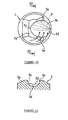
- This spray recess part 5b is formed with a roughly egg-shaped profile in plan view ( Figure 10) with the parts further forward in the injection direction (to the left of the figure) being narrower than parts further to the rear in the injection direction (to the right of the figure).
- said spray recess part 5b when viewed in cross section ( Figure 9) along a direction perpendicular to the camshaft including the cylinder axis and fuel injection valve, its shape consists of an introduction surface 5d comprising a sloping surface that is roughly parallel to the axis B of said fuel injection valve 15, an inclined bottom surface which follows on from said introduction surface 5d and rises slightly toward the front in the fuel injection direction, and a guide surface 5c which follows on from said bottom surface and rises up vertically after an intervening curved surface having a relatively large R.
- said spray recess part 5b when viewed in a cross section plane ( Figure 11) parallel with the camshaft and including the cylinder axis, it forms a roughly semicircular shape having left and right side walls 5e, 5e which stand erect.
- said fuel injection valve 15 is attached to the cylinder head so that it is positioned below said air intake port 3d and roughly parallel to air intake port 3d as seen in the direction of the camshaft, and fuel injection nozzle 15a opens into combustion recess part 3a, so that the stream of air introduced from air intake port 3d and the stream of fuel injected from fuel injection valve 15 flow in roughly the same direction - i.e. in a direction along which intersection is suppressed - and thus stratification is promoted by suppressing mixing of the air and fuel.
- a spray recess part 5b into which the fuel F injected from said fuel injection valve 15 is guided is formed in the head part 5a of piston 5, and since this spray recess part 5b is displaced toward said injection nozzle 15a as viewed in the camshaft direction and is formed with a shape whereby the injected fuel is guided to electrodes 11a of spark plug 11 positioned roughly concentrically with the cylinder axis, a fuel mist whose density is made relatively high due to said stratification is guided to the spark plug electrodes 11a, and as a result stable combustion can be achieved with lean fuel/air mixes.
- said spray recess part 5b is formed with a roughly egg-shaped profile as viewed along the cylinder axis from the side of the combustion chamber, with the parts further forward in the injection direction (to the left of Figure 10) being narrower than the parts to the rear in the injection direction (to the right of Figure 10), the concentration of said injected fuel F is increased by constricting it at the tip of said spray recess part 5b in the injection direction, and stable operation can be achieved with even leaner fuel/air mixes by guiding the fuel to spark plug 11 in this state.
- the fuel F injected toward spray recess part 5b from said fuel injection valve 15 is smoothly guided into spray recess part 5b by introduction surface 5d comprising a sloping surface that is roughly parallel to the axis B of said fuel injection valve 15, and is then guided - by a subsequent bottom surface which rises slightly to the front of the injection direction and by a guiding surface 5c which rises vertically after an intervening curved surface of large R which follows the bottom surface - to the electrodes 11a of spark plug 11 situated above it, and as a result it is possible to achieve stable combustion with even leaner fuel/air mixes.
- introduction surface 5d comprising a sloping surface that is roughly parallel to the axis B of said fuel injection valve 15, and is then guided - by a subsequent bottom surface which rises slightly to the front of the injection direction and by a guiding surface 5c which rises vertically after an intervening curved surface of large R which follows the bottom surface - to the electrodes 11a of spark plug 11 situated above it, and as a result
- one of the pair of intake ports 3d on the left and right sides, preferably the left air intake port 3d of the two air intake ports 3d is closed off by a switching valve 13a (described below) when running with low quantities of intake air such as during idling, so that air is only introduced through the right air intake port 3d, thus giving rise to counterclockwise swirl (eddy, transverse eddies) in the cylinder as shown by the arrows in Figure 10, whereby the fuel F injected from said fuel injection valve 15 toward the interior of spray recess part 5b is pressed by this swirl to the downstream side of the swirl inside said spray recess part 5b.
- a switching valve 13a described below
- the fuel F that is pressed to one side by said swirl is concentrated inside spray recess part 5b by the right side wall 5e (the side wall to the top of Figure 10) which rises up from spray recess part 5b, and this pressing allows concentrated fuel to be guided to spark plug 11, thereby providing further assistance to achieving stable combustion with lean fuel/air mixes.
- Two air intake valve openings 3b and two exhaust valve openings 3c are formed in this combustion recess part 3a.
- the air intake valve opening 3b is guided out to the front wall 3e of cylinder head 3 by an air intake port 3d, and an exhaust valve opening 3c is guided out to the rear wall 3g by an exhaust port 3f.
- Said air intake port 3d extends forward and upward so that its axis Ci forms a clockwise angle of 40 to 60° with respect to the cylinder axis C, and said exhaust port 3f extends roughly horizontally so that its axis Ce forms a counterclockwise angle of 75 to 95° with respect to the cylinder axis C.
- An air intake system 13 is connected to the external connection hole 3d' of said air intake port 3d, and an exhaust system 14 is connected to the external connection hole 3g' of said exhaust port 3g.
- Said air intake system 13 is configured by connecting a connecting duct 13b - which incorporates a switching valve 13a that opens and closes the air intake port 3d on the left side as seen from the front of the vehicle - to said external connection hole 3d', and by then sequentially connecting an air intake pipe 13c, a surge tank 13d and an air cleaner (not illustrated) thereto.
- 3p is a bolt hole for fixing the connecting duct 13b.
- said exhaust system 14 is configured by connecting parts such as an exhaust manifold 14a, exhaust pipe 14b and a muffler (not illustrated) to said external connection hole 3g'.
- an air intake valve 7 is disposed in each of the said air intake valve openings 3b and an exhaust valve 8 is disposed in each of said exhaust valve openings 3c; said air intake valve 7 and exhaust valve 8 are opened and closed by an air intake valve operating mechanism 9 and an exhaust valve operating mechanism 10.
- Said air intake and exhaust valve mechanisms 9 and 10 are configured so that the air intake valves 7 and exhaust valves 8 are pushed home by valve springs 9a and 10a and are opened and closed by air intake and exhaust camshafts 9c and 10c via lifters 9b and 1Ob fitted at the top end thereof.
- the fuel supply device 12 in this engine 1 is equipped with a fuel supply system comprising fuel injection valves 15 - one of which is fitted in each cylinder -, a single fuel rail 16 which is shared by each of the three fuel injection valves 15, and a high-pressure fuel pump 27 and fuel ducts (not illustrated) which supply high-pressure fuel to this fuel rail 16.
- said fuel injection valves 15 are disposed at the center (boundary part) of the left and right air intake ports 3d, 3d in the direction of the camshaft as seen from the front of the vehicle, and when viewed along the direction of the camshaft, their axis B is disposed roughly parallel with the axis Ci of said air intake port 3d and closer toward axis Ci of air intake port 3d.
- the parts nearer the boundary of the bottom wall of left and right air intake ports 3d, 3d is formed so as to cut into the interior of the air intake port, and said fuel injection valve 15 is disposed in the space a obtained by providing this cutin part 3n.
- said fuel injection valves 15 comprise a slender cylindrical nozzle part 15a having an injection outlet, a wide cylindrical main body part 15b which accommodates a solenoid or the like, and a cylindrical fuel introduction part 15c to which said fuel rail 16 is connected. Also, the step part between said wide main body part 15b and said introduction part 15c constitutes a flange part 15d for clamping the fuel injection valve 15 onto the engine, and a tapering valve side positioning part 15e is formed at the boundary part between said main body part 15b and the nozzle part 15a.
- Said nozzle part 15a is inserted into a nozzle hole 3h which opens into said combustion recess part 3a of the valve attachment hole formed in cylinder head 3; the tip thereof is positioned near the interior surface of combustion recess part 3a, and the gap between nozzle part 15a and nozzle hole 3h is sealed by a sealing ring 15g.
- said main body part 15b is inserted into a part of retaining hole 3i of said valve attachment hole, and valve side positioning part 15e comes into contact with a head side positioning part 3j which has the shape of a tapering hole formed in the cylinder head, whereby it is positioned inside the valve attachment hole of fuel injection valve 15 and the combustion pressure is prevented from escaping to the outside.
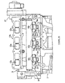
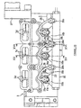
- Said fuel rail 16 has the shape of a round pipe which extends parallel with the camshaft, and the fuel introduction part 15c of fuel injection valve 15 is disposed to the front of said fuel injection valve 15 as viewed in the direction of axis B of fuel injection valve 15 (see Figure 4), and is separated from it by a sufficient gap so as not to be hidden below fuel rail 16.
- three fuel supply parts 16a and three supporting stay parts 16b are integrally formed in said fuel rail 16.
- Said fuel supply parts 16a extend rearward toward the front wall 3e of the engine so as to cover the fuel introduction part 15c of said fuel injection valves 15, an interlocking hole 16c formed in the extended end part of fuel supply part 16a is interlocked with the fuel introduction part 15c of fuel injection valve 15, and the gap between introduction part 15c and interlocking hole 16c is sealed by an O-ring 15f.
- item 16e is a connecting hole which connects fuel rail 16 with said interlocking hole 16c.
- said supporting stay parts 16b extend rearward toward the front wall 3e of the engine, and the flange parts 16d at the tips of these supporting stay parts 16b are secured and fixed to rail attachment boss parts 3m - which also serve as fuel injection valve attachment boss parts and are formed in cylinder head 3 - by bolts 22 with intervening leaf springs (valve clamping members) 20. Fuel injection valves 15 are clamped to cylinder head 3 by these leaf springs 20.
- space a is provided so as to cut into the interior of air intake port 3d at the boundary part of the pair of air intake ports 3d, 3d on the left and right sides, and said fuel injection valve 15 is inserted into and disposed in this space a, fuel injection valve 15 can be disposed roughly parallel with air intake port 3d while making the parts of cylinder head 3 around fuel injection valve 15 more compact, and as mentioned above this has the result of facilitating stratification of the air and fuel by supplying the air and fuel into the cylinder in the same direction, thereby making it possible to achieve stable combustion with lean fuel/air mixes and providing for improved fuel economy and cleaner exhaust emissions.
- fuel rail attachment bolts 22 and fuel injection valve attachment bolts 19 are screwed in along a direction parallel with said fuel injection valve axis B, it is possible to avoid problems such as tools hitting fuel rail 16 when these bolts 22, 19 are screwed in, and the assembly operation can be further improved.
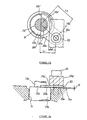
- a leaf spring 20 which is part of a valve clamping member 18, is then clamped into place on said valve attachment boss part 3k by an attachment bolt 19, covering washer member 21, and the left and right tip parts 20c' of this leaf spring 20 press against said flange part 15d, whereby fuel injection valve 15 is fixed to cylinder head 3.
- Said leaf spring 20 and washer member 21 are fixed by soldering, and said washer member 21 is made of highly rigid steel sheet of greater thickness than leaf spring 20 (preferably with a sheet thickness of at least 3 mm), and has a fixing part 21a which is fixed by bolt 19, and an elongated part 21b for applying a clamping force uniformly to the left and right tip parts 20c', 20c' of the contacting edge 20c of said leaf spring 20 which is formed in the shape of a circular arc.
- Said leaf spring 20 is made of spring steel sheet with a thickness of 0.5 to 3.0 mm, preferably 1.5 mm, and it is equipped with a fixing part 20a which has the same shape as said washer member 21 in plan view and a clamping part 20b which projects forward from washer member 21. Said clamping part 20b of said leaf spring 20 is bent down along the line of the tip edge 21c of said washer member 21.
- the amount A of said curvature in clamping part 20b is set so that elastic deformation occurs in leaf spring 20 when fuel injection valve 15 is fixed in the normal state by said leaf spring 20 and the dimension H of the difference in height between flange part 15d of said fuel injection valve 15 and the valve attachment boss part 3k on the side of the cylinder head swings toward the side of (standard dimension plus tolerance), i.e. when said difference dimension H has become larger then the standard dimension, and leaf spring 20 is subjected to both elastic and plastic deformation when said difference dimension H swings toward the side of (standard dimension minus tolerance), i.e. when said difference dimension H has become smaller than the standard dimension.
- Fuel injection valve 15 can thereby be securely fixed to the engine by accommodating the abovementioned dimensional tolerance, and since leaf spring 20 in the first embodiment is made of a thin sheet with a thickness of about 0.5 to 3.0 mm, it does not apply an excessive clamping force that would damage fuel injection valve 15, even if leaf spring 20 is tightened to such a degree that said plastic deformation occurs.
- the abovementioned amount A of curvature in said leaf spring 20 can also be set so that plastic deformation occurs in addition to elastic deformation in said leaf spring 20 when the abovementioned difference dimension H swings toward the side of (standard dimension plus tolerance), i.e. when said difference dimension H has become larger than the standard dimension.
- the present invention also includes the setting of the amount of curvature in this way.
- said amount of curvature A is specifically set in the following way, for example. That is, when said fuel injection valves 15 are inserted into retaining holes 3i and the valve side positioning part 15e is brought into contact with the head side positioning part 3j, the dimension H of the difference in height between flange part 15d and valve attachment boss part 3k is kept within a standard dimension of 0.3 mm, plus or minus a tolerance of 0.3 mm. Also, said amount of curvature A is set to 0.95 ⁇ 0.25 mm. Accordingly, said difference dimension H becomes 0 mm when it has swung to its largest negative value, in which case leaf spring 20 is deformed by about 0.95 mm and is subjected to a plastic deformation of about 0.4 mm. Note that the dimensions L1, L2 and L3 in Figure 12 are - for example - set to approximately 16, 7 and 20 mm respectively.
- fuel injection valves 15 are attached to cylinder head 3 by inserting fuel injection valves 15 into the valve attachment holes and bringing the valve side positioning parts 15e into contact with the head side positioning parts 3j, and the flange parts 15d of said fuel injection valves 15 are fixed by clamping them with leaf springs 20 - which are made of thin sheet and are attached to cylinder head 3 - and tightening attachment bolts 19.
- the dimensional tolerance between the flange parts 15d of fuel injection valves 15 and the valve attachment boss parts 3k of cylinder head 3 are accommodated by elastic deformation of thin sheet leaf springs 20, and when said dimensional tolerance is large it is accommodated by plastic deformation of said leaf springs 20 in addition to elastic deformation.
- said leaf spring 20 is made of a thin sheet, excessive clamping forces do not act on the fuel injection valves even if the clamping force is increased to such a degree that said thin sheet is subjected to plastic deformation.
- said leaf springs 20 are made of spring steel sheet with a thickness of 1.0 to 3.0 mm and said reference dimension is set to 0.3 mm so that flange parts 15d become lower than valve attachment boss parts 3k, in which case said difference H becomes smaller than the reference dimension (e.g. 0 mm) when said tolerance has become negative (e.g. -0.3 mm), and when said leaf springs 20 are clamped by tightening attachment bolts 19, said leaf springs 20 (which are made of thin sheet) are not only elastically deformed but are also subjected to about 0.4 mm of plastic deformation, so that fuel injection valves 15 can be securely fixed to cylinder head 3 by a simple operation without performing precise torque control and without subjecting them to excessive clamping forces.
- said leaf springs 20 are of a single-grip type, having a fixing part 20a extending obliquely radially outward from one end of said clamp part 20b, and since they are secured by bolts 19 to said valve attachment boss parts 3k in such a way that they cover washer members 21 which have higher rigidity than said leaf springs 20 at said fixing part 20a and which have an elongated part which extends to the other end of said clamp part 20b, it is possible to save space by using single-grip leaf springs 20 and it is possible to apply a uniform clamping force to both tip parts 20c', 20c' of said clamp part 20b from one end to the other, and the fuel injection valves 15 can be securely fixed to cylinder head.
- fuel injection valves 15 can be disposed roughly parallel with air intake ports 3d, stratification of the fuel and air can be promoted by introducing the fuel and air into the cylinders in the same direction, allowing stable combustion to be achieved with lean fuel/air mixtures.
- space a is provided so as to cut into the interior of air intake ports 3d at the boundary part of the pair of air intake ports 3d, 3d on the left and right sides, and said fuel injection valves 15 are inserted into and disposed in this space a, fuel injection valves 15 can be disposed roughly parallel with air intake ports 3d while making the parts of cylinder head 3 around fuel injection valves 15 more compact, stratification of the air and fuel can be promoted by supplying the air and fuel into the cylinders in the same direction, and it is thereby possible to achieve stable combustion with lean fuel/air mixtures which provides for improved fuel economy and cleaner exhaust emissions.
- sail rail attachment boss parts 3m are made to project in the axial direction of said fuel injection valves, it is possible to reduce the length of supporting stay 16b on the side of said fuel rail 16 in the axial direction of said fuel injection valves, and it is possible to increase the rigidity while achieving weight reductions in parts of said supporting stay 16b.
- fuel rail attachment bolts 22 and fuel injection valve attachment bolts 19 are screwed in along a direction parallel with said fuel injection valve axis, it is possible to avoid problems such as tools hitting fuel rail 16 when these bolts 22, 19 are screwed in, and the assembly operation can be further improved.
- Figures 14 through 17 illustrate a second embodiment not forming part of the present invention relating to another kind of valve clamping member, wherein leaf springs are provided having a pair of fixing parts on the left and right, and in these figures parts that are identical or correspond to those in Figures 1 through 13 are shown with the same reference numerals.
- the flange parts 15d of fuel injection valves 15 are clamped by a single leaf spring 25.
- This leaf spring 25 is made of spring steel sheet with a thickness of 0.5 to 3.0 mm, preferably 1.5 mm, and is equipped with a pair of left and right fixing parts 25a, 25a and a clamp part 25b situated between these fixing parts 25a, 25a.
- This clamp part 25b is folded down at a fold line n.
- the amount of abovementioned folding A of said clamp part 25b is set so that elastic deformation occurs in said leaf spring 25 when fuel injection valve 15 is fixed in the normal state by said leaf spring 25 and the dimension H of the difference in height between flange part 15d of said fuel injection valve 15 and the valve attachment boss part 3k on the side of the cylinder head swings toward the side of (standard dimension plus tolerance), i.e. when said difference dimension H has become larger then the standard dimension, and said leaf spring 25 is subjected to both elastic and plastic deformation when said difference dimension H swings toward the side of (standard dimension minus tolerance), i.e. when said difference dimension H has become smaller than the standard dimension.
- Fuel injection valve 15 can thus be securely fixed to the engine without causing any damage to the fuel injection valve itself.
- said amount of curvature A is specifically set in the following way, for example. That is, when said fuel injection valves 15 are inserted into retaining holes 3i and the valve side positioning parts 15e are brought into contact with the head side positioning parts 3j, the dimension H of the difference in height between flange parts 15d and valve attachment boss parts 3k is set so as to keep it within a standard dimension of 0.3 mm, plus or minus a tolerance of 0.3 mm. Also, said amount of curvature A is set to 0.95 ⁇ 0.25 mm.
- said difference dimension H becomes 0 mm when it has swung to its largest negative value, in which case leaf springs 25 are thus deformed by about 0.95 mm and are subjected to a plastic deformation of about 0.4 mm.
- the dimension L4 in Figure 16 is - for example - set to approximately 20 mm.
- the dimensional tolerance between the flange parts 15d of fuel injection valves 15 and the valve attachment boss parts 3k of cylinder head 3 can be accommodated by elastic deformation followed by plastic deformation of leaf springs 25, excessive clamping forces do not act on the fuel injection valves, and precise torque control is unnecessary, making the assembly operation more efficient.
- the clamping force can be made to act even more uniformly over flange parts 15d of fuel injection valves 15 from both tip parts 25c' of clamp edge parts 25c of said leaf springs 25, and fuel injection valves 15 can be securely fixed to cylinder head 3.
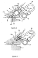
- Said leaf spring 20 is clamped by flange part 16d of said supporting stay part 16b, and since the flange part 16d is highly rigid, a uniform clamping force is made to act upon it by the left and right tip parts 20c', 20c' of the peripheral part 20c formed in the shape of an arc at the tip of said leaf spring 20.
- said leaf spring 20 is made of spring steel sheet with a thickness of 0.5 to 3.0 mm, preferably 1.5 mm, and it is equipped with a fixing part 20a which is clamped by said flange part 16d in plan view and a clamping part 20b which projects forward from flange part 16d. Said clamping part 20b of said leaf spring 20 is bent down along the line of the tip edge 16d' of flange part 16d.
- the amount A of said curvature in clamping part 20b is set so that elastic deformation occurs in leaf spring 20 when the dimension H of the difference in height between flange part 15d of said fuel injection valve 15 and the rail attachment boss part 3m on the side of the cylinder head swings toward the side of (standard dimension plus tolerance), i.e. when said difference dimension H has become larger then the standard dimension, and leaf spring 20 is subjected to both elastic and plastic deformation when said difference dimension H swings toward the side of (standard dimension minus tolerance), i.e. when said difference dimension H has become smaller than the standard dimension.
- Fuel injection valve 15 can thereby be securely fixed to the engine, and since leaf spring 20 in the present embodiment is made of a thin sheet with a thickness of about 0.5 to 3.0 mm, it does not apply an excessive clamping force that would damage fuel injection valve 15, even if leaf spring 20 is tightened to such a degree that the abovementioned plastic deformation occurs.
- the abovementioned amount of curvature A is specifically set in the following way, for example. That is, when said fuel injection valve 15 is inserted into retaining hole 3i and the valve side positioning part 15e is brought into contact with the head side positioning part 3j, the dimension H of the difference in height between flange part 15d and rail attachment boss part 3m is kept within a standard dimension of 0.3 mm, plus or minus a tolerance of 0.3 mm. Also, the abovementioned amount of curvature A is set to 0.95 ⁇ 0.25 mm.
- said difference dimension H becomes 0 mm when it has swung to its largest negative value, in which case leaf spring 20 is deformed by about 0.95 mm and is subjected to a plastic deformation of about 0.4 mm.
- the dimensions L1, L2 and L3 in Figure 8 are set to approximately 16, 7 and20 mm respectively.
- leaf spring 20 - which fixes the fuel injection valves - is gripped in place by flange part 16d of supporting stay part 16b of fuel rail 16 and rail attachment boss part 3m of cylinder head 3, it is possible to do away with a dedicated boss part for fixing the fuel injection valves, allowing corresponding space savings to be made, and it is also possible to enlarge the water-cooling jacket and improve the flow of cooling water since there is no need for bolt holes for the valve attachment boss part.
- the fuel injection valves 15 can be attached at the same time as the fuel rail 16 is fixed to cylinder head 3 if leaf spring 20 is interspersed between them, it is possible to reduce the amount of labor required for assembly and to make the assembly operation more efficient.
- fuel injection valve 15 can be disposed roughly parallel with air intake port 3d, stratification of the fuel and air can be promoted by introducing the fuel and air into the cylinder in the same direction, allowing stable combustion to be achieved with lean fuel/air mixtures.
- a rail attachment boss part 3m for bolting fuel rail 16 to cylinder head 3 is fitted on the right side of fuel injection valve 15 as seen in the direction of fuel injection valve axis B and this rail attachment boss part 3m is made to face outward from between air intake port 3d and fuel rail 16, the operation of attaching fuel rail 16 can be made easier without fuel rail 16 itself getting in the way.
- space a is provided so as to cut into the interior of air intake port 3d at the boundary part of the pair of air intake ports 3d, 3d on the left and right sides, and said fuel injection valve 15 is inserted into and disposed in this space a, fuel injection valve 15 can be disposed roughly parallel with air intake port 3d while making the parts of cylinder head 3 around fuel injection valve 15 more compact, stratification of the air and fuel can be promoted by supplying the air and fuel into the cylinder in the same direction, and it is thereby possible to achieve stable combustion with lean fuel/air mixtures which provides for improved fuel economy and cleaner exhaust emissions.
- fuel rail attachment bolt 22 is screwed in along a direction parallel with said fuel injection valve axis B, it is possible to avoid problems such as tools hitting fuel rail 16 when this bolt 22 is screwed in, and the assembly operation can be further improved.
- Figures 25 through 28 illustrate a fourth embodiment not forming part of the invention similar to the second embodiment relating to a second aspect.
- the fourth embodiment is an example wherein a pair of supporting stays are provided on the left and right sides, and in these figures parts that are identical or correspond to those in Figures 1 through 17 are shown with the same reference numerals.
- a pair of supporting stay parts 16b, 16b on the left and right sides are integrally formed with fuel rail 16 adjacent to fuel injection valves 15 on both sides in the direction of the camshaft, and a single leaf spring (valve clamping member) 25 is clamped in place by the flange parts 16d of both supporting stay parts 16b.
- This leaf spring 25 is made of spring steel sheet with a thickness of 0.5 to 3.0 mm, preferably 1.5 mm or thereabouts, and is equipped with a fixing part 25a which is clamped by said pair of left and right flange parts 16d, 16d in plan view and a clamp part 25b which is positioned between these flange parts 16d, 16d.
- This clamp part 25b is bent down along the line of the tip edge 16d' of said flange part 16d.
- the amount A of said curvature in clamp part 25b is set so that elastic deformation occurs in leaf spring 25 when the dimension H of the difference in height between flange part 15d of said fuel injection valve 15 and the rail attachment boss part 3m on the side of the cylinder head swings toward the side of (standard dimension plus tolerance), and leaf spring 25 is subjected to both elastic and plastic deformation when said difference dimension H swings toward the side of (standard dimension minus tolerance), as in the first three embodiments.
- FIGS 29 to 31 illustrate a fifth embodiment not forming part of the invention relating to the second aspect of the invention.
- This embodiment is an example, wherein the fuel injection valve clamping parts are integrally formed in the fuel rail itself, and in these figures parts that are identical or correspond to those in Figures 1 through 28 are shown with the same reference numerals.
- Three valve clamping stay parts 16h and two supporting stay parts 16i are formed adjacent to each other on fuel rail 16.
- the supporting stay part 16i on the left side of Figure 14 is fitted adjacent to the valve clamping stay part 16h of the fuel injection valve 15 at the leftmost cylinder, and the supporting stay part 16i on the right side is fitted in the middle of the other two cylinders.
- Each of said supporting stay parts 16i is then fixed to rail attachment boss part 3m of cylinder head 3 by bolt 22, whereby each of said valve clamping stay parts 16h clamps the flange part 15d of each fuel injection valve 15.
- a coned disk spring 15h is interspersed between said valve clamping stay part 16h and flange part 15d, and this coned disk spring 15h has a similar function to leaf springs 20 and 25 in the abovementioned embodiments.
- downstream end part of fuel supply pipe 26 is connected by screwing joint 26a into the fuel introduction part 15c of each of said fuel injection valves 15.
- the upstream end of each of said fuel supply pipes 26 is connected by a joint 26b to a part of fuel rail 16 displaced in the camshaft direction by an amount E from each fuel injection valve.
- fuel rail 16 is provided with a supporting stay part 16i and valve clamping stay part 16h and each of said valve clamping stay parts 16h clamps the flange part 15d of each of the abovementioned fuel injection valves 15 via coned disk spring 15h when supporting stay part 16i is attached to cylinder head 3, it is possible to achieve a reliable flow of cooling water by preventing constriction of the water cooling jacket, and it is also possible to fix fuel injection valves 15 at the same time as fuel rail 16 is fixed to the engine, thereby making the assembly work more efficiently.
- supporting stay part 16i and said valve clamping stay part 16h are provided adjacent to each other in the direction of the camshaft, supporting stay part 16i, valve clamping stay part 16h and fuel injection valves 15 come to roughly the same positions in the direction perpendicular to the fuel rail axis, whereby it is possible to make do with less room in the direction perpendicular to these fuel rails and it is easy to make enough room in which to place them.
Landscapes
- Engineering & Computer Science (AREA)
- Chemical & Material Sciences (AREA)
- Combustion & Propulsion (AREA)
- Mechanical Engineering (AREA)
- General Engineering & Computer Science (AREA)
- Fuel-Injection Apparatus (AREA)
- Cylinder Crankcases Of Internal Combustion Engines (AREA)
Description
- The present invention relates to a direct injection type internal combustion engine according to the preamble of claim 1.
- Direct injection type combustion engines, also known as in-cylinder fuel-injected engines, wherein fuel is supplied by injecting it directly into the cylinders (cylinder bores), have recently attracted attention as a possible means of achieving increased power output and cleaner exhaust. This type of engine is constructed with fuel injection valves - which inject fuel directly into the cylinders - attached to the cylinder head, and a fuel rail - which supplies fuel to said fuel injection valves - connected to said fuel injection valves.
- An example of the abovementioned structure for attaching the fuel injection valves and fuel rail to the cylinder head is disclosed in Unexamined Published Japanese Patent Application (JP-A) No. H8-312503. This conventional structure is configured by disposing the fuel rail so that it covers the fuel introduction part of the fuel injection valve, bolting a supporting stay that is formed so as to project in a perpendicular axis to said fuel rail to the cylinder head, bolting a clamping member for fixing the fuel injection valves to the cylinder head, and clamping the flange parts of the fuel injection valves with the tip of said clamping member.
- In the abovementioned conventional engine, a structure is employed whereby the rail attachment boss part for attaching the fuel rail to the cylinder head and the valve attachment boss part for attaching the fuel injection valves to the cylinder head are formed separately; however, this leads to problems in that it is difficult to make enough room for these two boss parts on the cylinder head, and in that the assembly requires a large amount of labor because the fuel rail and fuel injection valves are fixed separately.
- In particular, when the fuel injection valves are provided at the air intake port side parts of the cylinder head so that their injection outlets open into the combustion cavity, the fuel injection valves are disposed in a narrow part between the air intake ports of the cylinder head and the interface of the cylinder block side surface, but the nature of these parts is such that there is little room available, and it is difficult to form said two boss parts on the cylinder head.
- Also, when the rail attachment boss part and valve attachment boss part are formed on said cylinder head, screw holes are needed for the attachment bolts; however, the boss parts for the provision of screw holes project toward the water-cooling jacket inside the cylinder head, resulting in a corresponding narrowing of the water-cooling jacket that could impede the flow of cooling water.
- Incidentally, said fuel rail is subjected to large reaction forces, which act toward the outside in the direction of the fuel injection valve axis, due to the high pressures that occur in the fuel inside it as the fuel injection valves open and close. In the conventional structure described in the abovementioned publication, said supporting stays project out away from the fuel rail, and the parts that are separated from said fuel rail are fixed to the cylinder head, so that a bending moment acts due to the abovementioned reaction forces, and accordingly there have been problems in that the rigidity of the supporting stay parts must be increased to enable them to withstand this bending moment, resulting in a corresponding increase in the weight of the engine.
- Also, since the fuel injection valves and supporting stays are separated from each other in the direction perpendicular to the fuel rail axis, they require a large amount of space; in particular, it is difficult to secure the space required for optimal placement, such as disposing the fuel injection valves adjacent to the air intake ports and roughly parallel with said ports, with the resulting problem that constraints are imposed on the layout freedom.
- Incidentally, although a characterizing feature of the abovementioned in-cylinder fuel injected engine is that the fuel/air mix is much leaner than the theoretical fuel/air mix, stabilizing this sort of lean combustion necessitates stratifying the injected fuel and air and guiding this stratified - and thus easily combusted - fuel layer to the vicinity of the spark plug.
- Further, JP-A No. H8-312503 presents a conventional structure which is configured by providing the fuel injection valves with a flange part and a sealing surface, fixing the said fuel injection valves into position in the cylinder head by clamping the upper surface of said flange parts with a highly rigid valve clamping member fixed to the cylinder head, thereby bringing the lower surface of said flange parts into contact with the cylinder head side, and accommodating process tolerances between the fuel injection valves, valve attachment holes and clamping members by interspersing an elastically compressible gasket between the sealing surface of the fuel injection valves and the sealing surface of the valve attachment holes in the cylinder head.
- However, since the abovementioned conventional engine is configured so that the fuel injection valves are clamped to the cylinder head by highly rigid clamping members, there is a problem in that the clamping force applied to the fuel injection valves can vary greatly according to the dimensional tolerances between the fuel injection valves themselves and the valve attachment holes in the cylinder head.
- Furthermore, in the abovementioned conventional engine, although said dimensional tolerances are accommodated by elastic compression of the gasket, there is a limit to the amount of elastic compression in said gasket and it is difficult to fully accommodate large dimensional tolerances. Also, in the abovementioned conventional engine, the valve clamping members are configured as elastic bodies and elastic forces are exerted on the fuel injection valves by adjusting the amount by which the attachment bolts are screwed into the engine; however, adjusting these screw amounts generally requires precise torque control using a special tool with the resulting problem that the assembly work is inefficient.
- Besides, a direct injection type internal combustion engine of the above kind is known from US 5,709,190 A.
- Therefore, it is an objective of the invention to provide an improved direct injection type internal combustion engine that provides a fuel injection valve attachment structure whereby the fuel injection valves can be securely attached to the cylinder head with a simple structure, and which can be assembled efficiently.
- For a direct injection type internal combustion engine of the above kind, this objective is solved in an inventive manner by the characterizing features of claim 1.
- Since said fuel rail is fitted offset toward the side opposite said air intake ports and astride said fuel injection valves, and since the rail attachment boss parts are formed at parts facing out from between the air intake ports and fuel rail, the positions of the fuel injection valves and the attachment positions of the fuel rail supporting stays on the cylinder head come to approximately the same position in the direction at right angles to the axis of the fuel rail, thereby allowing the bending moment arising from reaction forces to the abovementioned fuel pressure to be correspondingly reduced, and making it possible to avoid problems such as increased weight due to increasing the rigidity of the supporting stay parts.
- Also, since the supporting stays and fuel injection valves are situated in roughly the same position in the direction perpendicular to the fuel rail, it is possible to make do with less space for the supporting stays and fuel injection valves in the direction perpendicular to the fuel rail, making the region surrounding the fuel injection valves on the cylinder head more compact, and it is possible to achieve greater freedom in the layout, such as disposing the fuel injection valves roughly parallel with the air intake ports and adjacent to these air intake ports. And since the fuel injection valves can be disposed roughly parallel with the air intake ports, the fuel and air can be introduced into the cylinders in the same direction, thereby promoting stratification of the fuel and air and allowing stable combustion to be achieved with lean fuel/air mixes.
- Furthermore, since the rail attachment bosses to which the supporting stays are bolted are disposed facing out from between the air intake ports and the fuel rail, no obstructions are caused by the fuel rail itself during the attachment operation, making the attachment operation more efficient.
- Since rail attachment boss parts are disposed on one side of the fuel injection valves either on or adjacent to a straight line parallel with the camshaft that intersects the fuel injection valve axis as seen in the direction of the fuel injection valve axis, and since valve attachment boss parts for bolting said fuel injection valves to the cylinder head are formed on the other side, it is possible to make do with less space for the supporting stays, fuel injection valves and valve attachment boss parts in the direction perpendicular the fuel rail axis, and in this case it is also possible to increase the layout freedom of the fuel injection valves while making the parts of the cylinder head around the fuel injection valves more compact.
- Further, since a space that cuts into the interior of the air intake ports is provided at the boundary part of a pair of air intake ports on the left and right sides, and since the abovementioned fuel injection valves are disposed by inserting them into this space, the fuel injection valves can be disposed roughly parallel with the air intake ports while making the parts of the cylinder head around the fuel injection valves more compact, and stratification of the air and fuel can be promoted by supplying the air and fuel into the cylinders in the same direction, thereby allowing the engine to operate stably with lean fuel/air mixes, improving its fuel consumption and promoting cleaner exhaust emissions.
- Furthermore, since said rail attachment boss parts project in the direction of said fuel injection valve axis, it is possible to reduce the length of the supporting stays on said fuel rail in the direction of said fuel injection valve axis, and it is possible to increase the rigidity of these supporting stay parts while making them lighter.
- Additionally, since the fuel rail attachment bolts and fuel injection valve attachment bolts are screwed in along a direction parallel with said fuel injection valve axis, it is possible to avoid problems such as tools striking the fuel rail when these bolts are screwed in, thereby allowing the assembly operation to be made even more efficient.
- Further advantageous embodiments of the invention are laid down in the subclaims.
- In the following, the invention is explained in greater detail by means of an embodiment making reference to the accompanying drawings, wherein:
- Figure 1
- is a cross-sectional side view of an in-cylinder fuel-injected gasoline engine according to an embodiment of the present invention,
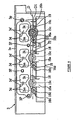
- Figure 2
- is a front view as seen in the direction of arrow II in Figure 1,
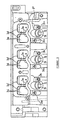
- Figure 3
- is a front view of just the cylinder head in Figure 1 as seen in the direction of arrow II,
- Figure 4
- is a front view of the region around the fuel rail as seen in the direction of arrow IV in Figure 1,
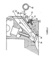
- Figure 5
- is a cross-sectional view along line V-V in Figure 2,
- Figure 6
- is a cross-sectional view along line VI-VI in Figure 2,
- Figure 7
- is a cross-sectional view along line VII-VII in Figure 2,
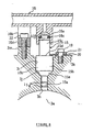
- Figure 8
- is a schematic view showing the attachment of the fuel injection valves and fuel rail in a first embodiment of said engine,
- Figure 9
- is a schematic cross-sectional side view showing how fuel injection is performed in said engine,
- Figure 10
- is a plan view of a piston in said engine,
- Figure 11
- is a cross-sectional view along line XI-XI in Figure 10,
- Figure 12
- is a plan view showing the attachment of the fuel injection valves in the above-mentioned first embodiment of Figure 8,
- Figure 13
- is a cross-sectional side view showing the attachment of the fuel injection valves in the above-mentioned first embodiment,
- Figure 14
- is a front view of an engine according to a second embodiment not forming part of the invention,
- Figure 15
- is a schematic cross-sectional side view showing the attachment of the fuel injection valves in the above-mentioned second embodiment,
- Figure 16
- is a plan view of the leaf spring in the above-mentioned second embodiment,
- Figure 17
- is a side view of the leaf spring in the above-mentioned second embodiment,
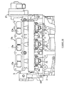
- Figure 18
- is a front view as seen in the direction of arrow II in Figure 1,
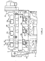
- Figure 19
- is a front view of just the cylinder head in Figure 1 as seen in the direction of arrow II,
- Figure 20
- is a front view of the region around the fuel rail as seen in the direction of arrow IV in Figure 1,
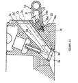
- Figure 21
- is a cross-sectional view along line VI-VI in Figure 18,
- Figure 22
- is a schematic view showing the attachment of the fuel injection valves and fuel rail in said engine according to a third embodiment,
- Figure 23
- is a plan view showing the attachment of the fuel injection valves of the third embodiment,
- Figure 24
- is a cross-sectional view showing the attachment of the fuel injection valves of the third embodiment,
- Figure 25
- is a front view of a direct injection type internal combustion engine according to a fourth embodiment not forming part of the invention,
- Figure 26
- is a schematic cross-sectional side view showing the attachment of the fuel rail and fuel injection valves in the above-mentioned fourth embodiment,
- Figure 27
- is a plan view of the leaf spring for attaching fuel injection valves in the engine of the above-mentioned fourth embodiment,
- Figure 28
- is a side view of the afore-mentioned leaf spring,
- Figure 29
- is a front view of an in-cylinder fuel-injected engine according to a fifth embodime not forming part of the invention relating to a second aspect of the invention,
- Figure 30
- is a cross-sectional view along line XV-XV in Figure 29, and
- Figure 31
- is a cross-sectional view along line XVI-XVI in Figure 29.
- In the figures, item 1 is a water-cooled four-stroke in-line 3-cylinder four-valve engine, and this engine 1 is mainly constructed with a
cylinder head 3 and a head cover 4 stacked on top of acylinder block 2, withpistons 5 inserted with freedom to slide inbore holes 2a incylinder block 2, and thepistons 5 linked to a crankshaft (not illustrated) bycon rods 6. - As shown in Figures 9 to 11, the
head part 5a of saidpistons 5 is made to protrude into a pentroof shape, and aspray recess part 5b into which the fuel is injected from a fuel injection valve 15 (described later) is formed in thehead part 5a. Thisspray recess part 5b is formed with a roughly egg-shaped profile in plan view (Figure 10) with the parts further forward in the injection direction (to the left of the figure) being narrower than parts further to the rear in the injection direction (to the right of the figure). - Also, when said
spray recess part 5b is viewed in cross section (Figure 9) along a direction perpendicular to the camshaft including the cylinder axis and fuel injection valve, its shape consists of anintroduction surface 5d comprising a sloping surface that is roughly parallel to the axis B of saidfuel injection valve 15, an inclined bottom surface which follows on from saidintroduction surface 5d and rises slightly toward the front in the fuel injection direction, and aguide surface 5c which follows on from said bottom surface and rises up vertically after an intervening curved surface having a relatively large R. Furthermore, when saidspray recess part 5b is viewed in a cross section plane (Figure 11) parallel with the camshaft and including the cylinder axis, it forms a roughly semicircular shape having left andright side walls - When the engine is idling, fuel is injected as
piston 5 rises from the position shown by the solid line in Figure 9 - i.e. about 60° (crank angle) before top dead center during the compression stroke - to around the position shown by the single-dot chain line (about 55° before top dead center). When saidpiston 5 reaches top dead center as shown by the two-dot chain line in the same figure, saidhead part 5a is positioned inside saidcombustion recess part 3a, and the electrodes 11a ofspark plug 11 are positioned insidespray recess part 5b of saidhead part 5a. - Thus in the present embodiment, said
fuel injection valve 15 is attached to the cylinder head so that it is positioned below saidair intake port 3d and roughly parallel toair intake port 3d as seen in the direction of the camshaft, andfuel injection nozzle 15a opens intocombustion recess part 3a, so that the stream of air introduced fromair intake port 3d and the stream of fuel injected fromfuel injection valve 15 flow in roughly the same direction - i.e. in a direction along which intersection is suppressed - and thus stratification is promoted by suppressing mixing of the air and fuel. - Also, since a
spray recess part 5b into which the fuel F injected from saidfuel injection valve 15 is guided is formed in thehead part 5a ofpiston 5, and since thisspray recess part 5b is displaced toward saidinjection nozzle 15a as viewed in the camshaft direction and is formed with a shape whereby the injected fuel is guided to electrodes 11a ofspark plug 11 positioned roughly concentrically with the cylinder axis, a fuel mist whose density is made relatively high due to said stratification is guided to the spark plug electrodes 11a, and as a result stable combustion can be achieved with lean fuel/air mixes. - Specifically, said
spray recess part 5b is formed with a roughly egg-shaped profile as viewed along the cylinder axis from the side of the combustion chamber, with the parts further forward in the injection direction (to the left of Figure 10) being narrower than the parts to the rear in the injection direction (to the right of Figure 10), the concentration of said injected fuel F is increased by constricting it at the tip of saidspray recess part 5b in the injection direction, and stable operation can be achieved with even leaner fuel/air mixes by guiding the fuel to sparkplug 11 in this state. - Also, the fuel F injected toward
spray recess part 5b from saidfuel injection valve 15 is smoothly guided intospray recess part 5b byintroduction surface 5d comprising a sloping surface that is roughly parallel to the axis B of saidfuel injection valve 15, and is then guided - by a subsequent bottom surface which rises slightly to the front of the injection direction and by a guidingsurface 5c which rises vertically after an intervening curved surface of large R which follows the bottom surface - to the electrodes 11a ofspark plug 11 situated above it, and as a result it is possible to achieve stable combustion with even leaner fuel/air mixes. - Furthermore, in the present embodiment, one of the pair of
intake ports 3d on the left and right sides, preferably the leftair intake port 3d of the twoair intake ports 3d is closed off by a switchingvalve 13a (described below) when running with low quantities of intake air such as during idling, so that air is only introduced through the rightair intake port 3d, thus giving rise to counterclockwise swirl (eddy, transverse eddies) in the cylinder as shown by the arrows in Figure 10, whereby the fuel F injected from saidfuel injection valve 15 toward the interior ofspray recess part 5b is pressed by this swirl to the downstream side of the swirl inside saidspray recess part 5b. In this case, the fuel F that is pressed to one side by said swirl is concentrated insidespray recess part 5b by theright side wall 5e (the side wall to the top of Figure 10) which rises up fromspray recess part 5b, and this pressing allows concentrated fuel to be guided to sparkplug 11, thereby providing further assistance to achieving stable combustion with lean fuel/air mixes. - A
combustion recess part 3a - which, along withhead part 5a ofpiston 5, constitutes the combustion chamber - is formed at the mating surface of saidcylinder head 3 where it meets the cylinder block. Two airintake valve openings 3b and two exhaust valve openings 3c are formed in thiscombustion recess part 3a. The airintake valve opening 3b is guided out to thefront wall 3e ofcylinder head 3 by anair intake port 3d, and an exhaust valve opening 3c is guided out to therear wall 3g by an exhaust port 3f. - Said
air intake port 3d extends forward and upward so that its axis Ci forms a clockwise angle of 40 to 60° with respect to the cylinder axis C, and said exhaust port 3f extends roughly horizontally so that its axis Ce forms a counterclockwise angle of 75 to 95° with respect to the cylinder axis C. - An
air intake system 13 is connected to theexternal connection hole 3d' of saidair intake port 3d, and anexhaust system 14 is connected to theexternal connection hole 3g' of said exhaust port 3g. Saidair intake system 13 is configured by connecting a connectingduct 13b - which incorporates a switchingvalve 13a that opens and closes theair intake port 3d on the left side as seen from the front of the vehicle - to saidexternal connection hole 3d', and by then sequentially connecting anair intake pipe 13c, asurge tank 13d and an air cleaner (not illustrated) thereto.
In Figure 4, 3p is a bolt hole for fixing the connectingduct 13b. Also, saidexhaust system 14 is configured by connecting parts such as anexhaust manifold 14a,exhaust pipe 14b and a muffler (not illustrated) to saidexternal connection hole 3g'. - Also, an air intake valve 7 is disposed in each of the said air
intake valve openings 3b and an exhaust valve 8 is disposed in each of said exhaust valve openings 3c; said air intake valve 7 and exhaust valve 8 are opened and closed by an air intakevalve operating mechanism 9 and an exhaustvalve operating mechanism 10. Said air intake andexhaust valve mechanisms valve springs exhaust camshafts 9c and 10c vialifters 9b and 1Ob fitted at the top end thereof. - The
fuel supply device 12 in this engine 1 is equipped with a fuel supply system comprising fuel injection valves 15 - one of which is fitted in each cylinder -, asingle fuel rail 16 which is shared by each of the threefuel injection valves 15, and a high-pressure fuel pump 27 and fuel ducts (not illustrated) which supply high-pressure fuel to thisfuel rail 16. - As shown in Figure 6, said
fuel injection valves 15 are disposed at the center (boundary part) of the left and rightair intake ports air intake port 3d and closer toward axis Ci ofair intake port 3d. In other words, the parts nearer the boundary of the bottom wall of left and rightair intake ports fuel injection valve 15 is disposed in the space a obtained by providing thiscutin part 3n. - In the present embodiment, since a configuration is adopted whereby the
fuel injection valves 15 are displaced toward theair intake ports 3d, it is possible to dispose thefuel injection valves 15 roughly parallel with theair intake ports 3d while making the configuration ofcylinder head 3 around the fuel injection valves more compact, and the injection nozzles can be made to face into saidcombustion recess parts 3a. Also, this parallel placement offuel injection valves 15 andair intake ports 3d allows the fuel and air to flow into the interior of the cylinders in the same direction, whereby stratification of the fuel and air can be achieved and stable combustion with a lean fuel/air mixture is made possible. - As shown in Figure 5, said
fuel injection valves 15 comprise a slendercylindrical nozzle part 15a having an injection outlet, a wide cylindricalmain body part 15b which accommodates a solenoid or the like, and a cylindricalfuel introduction part 15c to which saidfuel rail 16 is connected. Also, the step part between said widemain body part 15b and saidintroduction part 15c constitutes aflange part 15d for clamping thefuel injection valve 15 onto the engine, and a tapering valveside positioning part 15e is formed at the boundary part between saidmain body part 15b and thenozzle part 15a. - Said
nozzle part 15a is inserted into anozzle hole 3h which opens into saidcombustion recess part 3a of the valve attachment hole formed incylinder head 3; the tip thereof is positioned near the interior surface ofcombustion recess part 3a, and the gap betweennozzle part 15a andnozzle hole 3h is sealed by asealing ring 15g. Furthermore, saidmain body part 15b is inserted into a part of retaininghole 3i of said valve attachment hole, and valveside positioning part 15e comes into contact with a headside positioning part 3j which has the shape of a tapering hole formed in the cylinder head, whereby it is positioned inside the valve attachment hole offuel injection valve 15 and the combustion pressure is prevented from escaping to the outside. - Said
fuel rail 16 has the shape of a round pipe which extends parallel with the camshaft, and thefuel introduction part 15c offuel injection valve 15 is disposed to the front of saidfuel injection valve 15 as viewed in the direction of axis B of fuel injection valve 15 (see Figure 4), and is separated from it by a sufficient gap so as not to be hidden belowfuel rail 16. - As in Figure 5, three
fuel supply parts 16a and three supportingstay parts 16b are integrally formed in saidfuel rail 16. Saidfuel supply parts 16a extend rearward toward thefront wall 3e of the engine so as to cover thefuel introduction part 15c of saidfuel injection valves 15, an interlockinghole 16c formed in the extended end part offuel supply part 16a is interlocked with thefuel introduction part 15c offuel injection valve 15, and the gap betweenintroduction part 15c and interlockinghole 16c is sealed by an O-ring 15f. Note thatitem 16e is a connecting hole which connectsfuel rail 16 with said interlockinghole 16c. - As shown in Figures 5 to 8, said supporting
stay parts 16b extend rearward toward thefront wall 3e of the engine, and theflange parts 16d at the tips of these supportingstay parts 16b are secured and fixed to railattachment boss parts 3m - which also serve as fuel injection valve attachment boss parts and are formed in cylinder head 3 - bybolts 22 with intervening leaf springs (valve clamping members) 20.Fuel injection valves 15 are clamped tocylinder head 3 by these leaf springs 20. - With an in-cylinder fuel-injected gasoline engine 1, according to a first aspect of the invention, and relating to the present embodiment, as viewed in the direction of the fuel injection valve axis B, since said
fuel rail 16 is disposed offset toward the opposite side ofair intake port 3d astridefuel injection valve 15 and the railattachment boss part 3m on the side ofcylinder head 3 is formed at a part facing outwards from betweenair intake port 3d andfuel rail 16, the position offuel injection valve 15 and the attachment position of fuel rail supportingstay part 16b on the side of the cylinder head come to more or less the same position in the direction perpendicular to the axis offuel rail 16, whereby the bending moment resulting from the reaction to the fuel pressure is decreased and it is possible to avoid problems such as increased mass in order to increase the rigidity in parts of supportingstay 16b. - Also, since the positions of supporting
stay 16b andfuel injection valve 15 in the direction perpendicular to the axis fromfuel rail 16 are approximately the same, it is possible to make do with less space for supportingstay 16b andfuel injection valve 15 in said direction perpendicular to the axis, and the freedom of layout can be increased - for examplefuel injection valve 15 can be disposed roughly parallel withair intake port 3d and adjacent to thisair intake port 3d while making the region ofcylinder head 3 surroundingfuel injection valves 15 more compact. - Also, as viewed in the direction of fuel injection valve axis B, since a rail
attachment boss part 3m for boltingfuel rail 16 tocylinder head 3 is fitted on one side offuel injection valve 15 and avalve attachment seat 3k for bolting and fixing saidfuel injection valve 15 tocylinder head 3 is fitted on the other side, and since these parts are made to face outwards from betweenair intake port 3d andfuel rail 16, the operation of attachingfuel rail 16 can be made easier withoutfuel rail 16 itself getting in the way. It is also possible to make do with less space in the direction perpendicular to the fuel rail for the whole of valve attachment seats 3k,fuel injection valves 15 and the supporting stays 16b offuel rail 16, whereby the parts ofcylinder head 3 around thefuel injection valves 15 can be made more compact while increasing the layout freedom offuel injection valves 15. - Also, since space a is provided so as to cut into the interior of
air intake port 3d at the boundary part of the pair ofair intake ports fuel injection valve 15 is inserted into and disposed in this space a,fuel injection valve 15 can be disposed roughly parallel withair intake port 3d while making the parts ofcylinder head 3 aroundfuel injection valve 15 more compact, and as mentioned above this has the result of facilitating stratification of the air and fuel by supplying the air and fuel into the cylinder in the same direction, thereby making it possible to achieve stable combustion with lean fuel/air mixes and providing for improved fuel economy and cleaner exhaust emissions. - Also, since said rail
attachment boss parts 3m are made to project in the direction of said fuel injection valve axis B, the length of supportingstays 16b of saidfuel rail 16 can be reduced in the direction of said fuel injection valve axis B, whereby parts of supportingstays 16b can be reduced in weight while their rigidity can be increased. - Also, since fuel
rail attachment bolts 22 and fuel injectionvalve attachment bolts 19 are screwed in along a direction parallel with said fuel injection valve axis B, it is possible to avoid problems such as tools hittingfuel rail 16 when thesebolts - As shown in Figures 12 and 13, when a
fuel injection valve 15 is inserted into retaininghole 3i incylinder head 3 and valveside positioning part 15e is brought into contact with headside positioning part 3j, the dimension H of the difference in height between saidflange part 15d ofmain body part 15b and the valveattachment boss part 3k on the side ofcylinder head 3 is brought to a standard dimension within a certain tolerance either way, although it can fluctuate slightly from one engine to another due to process deviations. In a first embodiment, aleaf spring 20, which is part of avalve clamping member 18, is then clamped into place on said valveattachment boss part 3k by anattachment bolt 19, coveringwasher member 21, and the left andright tip parts 20c' of thisleaf spring 20 press against saidflange part 15d, wherebyfuel injection valve 15 is fixed tocylinder head 3. - Said
leaf spring 20 andwasher member 21 are fixed by soldering, and saidwasher member 21 is made of highly rigid steel sheet of greater thickness than leaf spring 20 (preferably with a sheet thickness of at least 3 mm), and has a fixingpart 21a which is fixed bybolt 19, and anelongated part 21b for applying a clamping force uniformly to the left andright tip parts 20c', 20c' of the contactingedge 20c of saidleaf spring 20 which is formed in the shape of a circular arc. - It is also possible to employ a method where said
leaf spring 20 andwasher member 21 are not soldered, thereby allowing the soldering process to be dispensed with. When this method is employed, a projecting part P is formed incylinder head 3 for alignment purposes as shown by the two-dot chain line in Figure 9, and thetip part 20c' (the part that comes into contact with the flange part) ofclamp part 20b ofleaf spring 20 can thereby easily be positioned at the correct position (a point on the line R through the center of the fuel injection valve) onflange part 15d offuel injection valve 15. - Said
leaf spring 20 is made of spring steel sheet with a thickness of 0.5 to 3.0 mm, preferably 1.5 mm, and it is equipped with a fixingpart 20a which has the same shape as saidwasher member 21 in plan view and aclamping part 20b which projects forward fromwasher member 21. Said clampingpart 20b of saidleaf spring 20 is bent down along the line of thetip edge 21c of saidwasher member 21. The amount A of said curvature in clampingpart 20b is set so that elastic deformation occurs inleaf spring 20 whenfuel injection valve 15 is fixed in the normal state by saidleaf spring 20 and the dimension H of the difference in height betweenflange part 15d of saidfuel injection valve 15 and the valveattachment boss part 3k on the side of the cylinder head swings toward the side of (standard dimension plus tolerance), i.e. when said difference dimension H has become larger then the standard dimension, andleaf spring 20 is subjected to both elastic and plastic deformation when said difference dimension H swings toward the side of (standard dimension minus tolerance), i.e. when said difference dimension H has become smaller than the standard dimension.Fuel injection valve 15 can thereby be securely fixed to the engine by accommodating the abovementioned dimensional tolerance, and sinceleaf spring 20 in the first embodiment is made of a thin sheet with a thickness of about 0.5 to 3.0 mm, it does not apply an excessive clamping force that would damagefuel injection valve 15, even ifleaf spring 20 is tightened to such a degree that said plastic deformation occurs. - Note that the abovementioned amount A of curvature in said
leaf spring 20 can also be set so that plastic deformation occurs in addition to elastic deformation in saidleaf spring 20 when the abovementioned difference dimension H swings toward the side of (standard dimension plus tolerance), i.e. when said difference dimension H has become larger than the standard dimension. The present invention also includes the setting of the amount of curvature in this way. - In the first embodiment, said amount of curvature A is specifically set in the following way, for example. That is, when said
fuel injection valves 15 are inserted into retainingholes 3i and the valveside positioning part 15e is brought into contact with the headside positioning part 3j, the dimension H of the difference in height betweenflange part 15d and valveattachment boss part 3k is kept within a standard dimension of 0.3 mm, plus or minus a tolerance of 0.3 mm. Also, said amount of curvature A is set to 0.95 ±0.25 mm. Accordingly, said difference dimension H becomes 0 mm when it has swung to its largest negative value, in whichcase leaf spring 20 is deformed by about 0.95 mm and is subjected to a plastic deformation of about 0.4 mm. Note that the dimensions L1, L2 and L3 in Figure 12 are - for example - set to approximately 16, 7 and 20 mm respectively. - With an in-cylinder fuel-injected gasoline engine 1, according to a second aspect of the invention, and relating to a first embodiment thereof,
fuel injection valves 15 are attached tocylinder head 3 by insertingfuel injection valves 15 into the valve attachment holes and bringing the valveside positioning parts 15e into contact with the headside positioning parts 3j, and theflange parts 15d of saidfuel injection valves 15 are fixed by clamping them with leaf springs 20 - which are made of thin sheet and are attached to cylinder head 3 - andtightening attachment bolts 19. In this case, the dimensional tolerance between theflange parts 15d offuel injection valves 15 and the valveattachment boss parts 3k ofcylinder head 3 are accommodated by elastic deformation of thin sheet leaf springs 20, and when said dimensional tolerance is large it is accommodated by plastic deformation of saidleaf springs 20 in addition to elastic deformation. And since saidleaf spring 20 is made of a thin sheet, excessive clamping forces do not act on the fuel injection valves even if the clamping force is increased to such a degree that said thin sheet is subjected to plastic deformation. - Also, since no problems arise even when
leaf spring 20 is tightened byattachment bolt 19 to such a degree that plastic deformation occurs according to the abovementioned dimensional tolerance, there is no need to perform precise torque control as in the conventional case where a highly rigid valve clamping member made of an elastic material is clamped to achieve a prescribed elastic force, and thus the assembly operation is made easier. - For example, in the present embodiment, said
leaf springs 20 are made of spring steel sheet with a thickness of 1.0 to 3.0 mm and said reference dimension is set to 0.3 mm so thatflange parts 15d become lower than valveattachment boss parts 3k, in which case said difference H becomes smaller than the reference dimension (e.g. 0 mm) when said tolerance has become negative (e.g. -0.3 mm), and when saidleaf springs 20 are clamped by tighteningattachment bolts 19, said leaf springs 20 (which are made of thin sheet) are not only elastically deformed but are also subjected to about 0.4 mm of plastic deformation, so thatfuel injection valves 15 can be securely fixed tocylinder head 3 by a simple operation without performing precise torque control and without subjecting them to excessive clamping forces. - Also, in the present embodiment, since said
leaf springs 20 are of a single-grip type, having a fixingpart 20a extending obliquely radially outward from one end of saidclamp part 20b, and since they are secured bybolts 19 to said valveattachment boss parts 3k in such a way that they coverwasher members 21 which have higher rigidity than saidleaf springs 20 at said fixingpart 20a and which have an elongated part which extends to the other end of saidclamp part 20b, it is possible to save space by using single-grip leaf springs 20 and it is possible to apply a uniform clamping force to bothtip parts 20c', 20c' of saidclamp part 20b from one end to the other, and thefuel injection valves 15 can be securely fixed to cylinder head. 3 - Also, in the present embodiment, as viewed in the direction of fuel injection valve axis B, since said
fuel rail 16 is disposed offset toward the opposite side ofair intake ports 3d astridefuel injection valves 15 and the railattachment boss part 3m on the side ofcylinder head 3 is formed at a part facing outward from betweenair intake port 3d andfuel rail 16, the positions offuel injection valves 15 more or less coincide with the attachment position of fuelrail supporting stay 16b on the side of the cylinder head in the direction perpendicular to the axis offuel rail 16, whereby the bending moment resulting from the reaction to the fuel pressure is decreased and it is possible to avoid problems such as increased mass in order to increase the rigidity in parts of supportingstay part 16b. - Also, since the positions of supporting
stay 16b andfuel injection valve 15 in the direction perpendicular to the axis fromfuel rail 16 are approximately the same, it is possible to make do with less space for supportingstay 16b andfuel injection valves 15 in said direction perpendicular to the axis, and the freedom of layout can be increased - for examplefuel injection valves 15 can be disposed roughly parallel withair intake ports 3d and adjacent to theseair intake ports 3d while making the region ofcylinder head 3 surroundingfuel injection valves 15 more compact. - Also, since
fuel injection valves 15 can be disposed roughly parallel withair intake ports 3d, stratification of the fuel and air can be promoted by introducing the fuel and air into the cylinders in the same direction, allowing stable combustion to be achieved with lean fuel/air mixtures. - Also, as seen in the direction of fuel injection valve axis B, since rail
attachment boss parts 3m for boltingfuel rail 16 tocylinder head 3 are fitted on one side offuel injection valves 15 and valveattachment boss parts 3k for bolting saidfuel injection valves 15 tocylinder head 3 are fitted on the other side, and since they are made to face outward from betweenair intake port 3d andfuel rail 16, the operation of attachingfuel rail 16 can be made easier withoutfuel rail 16 itself getting in the way. Also, less space is needed in the direction perpendicular to the fuel rail axis for the placement of the supportingstay 16b offuel rail 16,fuel injection valves 15 and the whole of valveattachment boss parts 3k, thereby allowing the region ofcylinder head 3 surroundingfuel injection valves 15 to be made more compact while increasing the layout freedom offuel injection valves 15. - Also, since space a is provided so as to cut into the interior of
air intake ports 3d at the boundary part of the pair ofair intake ports fuel injection valves 15 are inserted into and disposed in this space a,fuel injection valves 15 can be disposed roughly parallel withair intake ports 3d while making the parts ofcylinder head 3 aroundfuel injection valves 15 more compact, stratification of the air and fuel can be promoted by supplying the air and fuel into the cylinders in the same direction, and it is thereby possible to achieve stable combustion with lean fuel/air mixtures which provides for improved fuel economy and cleaner exhaust emissions. - Also, since sail rail
attachment boss parts 3m are made to project in the axial direction of said fuel injection valves, it is possible to reduce the length of supportingstay 16b on the side of saidfuel rail 16 in the axial direction of said fuel injection valves, and it is possible to increase the rigidity while achieving weight reductions in parts of said supportingstay 16b. - Also, since fuel
rail attachment bolts 22 and fuel injectionvalve attachment bolts 19 are screwed in along a direction parallel with said fuel injection valve axis, it is possible to avoid problems such as tools hittingfuel rail 16 when thesebolts - Figures 14 through 17 illustrate a second embodiment not forming part of the present invention relating to another kind of valve clamping member, wherein leaf springs are provided having a pair of fixing parts on the left and right, and in these figures parts that are identical or correspond to those in Figures 1 through 13 are shown with the same reference numerals.
- In the second embodiment, the
flange parts 15d offuel injection valves 15 are clamped by asingle leaf spring 25. Thisleaf spring 25 is made of spring steel sheet with a thickness of 0.5 to 3.0 mm, preferably 1.5 mm, and is equipped with a pair of left and right fixingparts clamp part 25b situated between these fixingparts clamp part 25b is folded down at a fold line n. The amount of abovementioned folding A of saidclamp part 25b is set so that elastic deformation occurs in saidleaf spring 25 whenfuel injection valve 15 is fixed in the normal state by saidleaf spring 25 and the dimension H of the difference in height betweenflange part 15d of saidfuel injection valve 15 and the valveattachment boss part 3k on the side of the cylinder head swings toward the side of (standard dimension plus tolerance), i.e. when said difference dimension H has become larger then the standard dimension, and saidleaf spring 25 is subjected to both elastic and plastic deformation when said difference dimension H swings toward the side of (standard dimension minus tolerance), i.e. when said difference dimension H has become smaller than the standard dimension.Fuel injection valve 15 can thus be securely fixed to the engine without causing any damage to the fuel injection valve itself. - In the present embodiment, said amount of curvature A is specifically set in the following way, for example. That is, when said
fuel injection valves 15 are inserted into retainingholes 3i and the valveside positioning parts 15e are brought into contact with the headside positioning parts 3j, the dimension H of the difference in height betweenflange parts 15d and valveattachment boss parts 3k is set so as to keep it within a standard dimension of 0.3 mm, plus or minus a tolerance of 0.3 mm. Also, said amount of curvature A is set to 0.95 ±0.25 mm. Accordingly, said difference dimension H becomes 0 mm when it has swung to its largest negative value, in whichcase leaf springs 25 are thus deformed by about 0.95 mm and are subjected to a plastic deformation of about 0.4 mm. Note that the dimension L4 in Figure 16 is - for example - set to approximately 20 mm. - In this second embodiment, as in the abovementioned first embodiment, the dimensional tolerance between the
flange parts 15d offuel injection valves 15 and the valveattachment boss parts 3k ofcylinder head 3 can be accommodated by elastic deformation followed by plastic deformation ofleaf springs 25, excessive clamping forces do not act on the fuel injection valves, and precise torque control is unnecessary, making the assembly operation more efficient. - Also, in the second embodiment, since the pair of fixing
parts 25a on the left and right ofleaf springs 25 are bolted down, the clamping force can be made to act even more uniformly overflange parts 15d offuel injection valves 15 from bothtip parts 25c' ofclamp edge parts 25c of saidleaf springs 25, andfuel injection valves 15 can be securely fixed tocylinder head 3. - In a third embodiment, as shown in Figures 18 to 24, same parts have the same reference numerals as above and mainly the differences to the first two embodiments are described hereafter.
- Here, when a
fuel injection valve 15 is inserted into retaininghole 3i incylinder head 3 and valveside positioning part 15e is brought into contact with headside positioning part 3j, the dimension H of the difference in height between saidflange part 15d ofmain body part 15b and the railattachment boss part 3m on the side ofcylinder head 3 is brought to a standard dimension within a certain tolerance either way, although it can fluctuate slightly from one engine to another due to process deviations. Then as mentioned above, saidleaf spring 20 is clamped against said railattachment boss part 3m as a valve clamping member, and the left andright tip parts 20c' of theperipheral part 20c of the tip of thisleaf spring 20 press against saidflange part 15d, wherebyfuel injection valve 15 is fixed tocylinder head 3. - Said
leaf spring 20 is clamped byflange part 16d of said supportingstay part 16b, and since theflange part 16d is highly rigid, a uniform clamping force is made to act upon it by the left andright tip parts 20c', 20c' of theperipheral part 20c formed in the shape of an arc at the tip of saidleaf spring 20. - In said third embodiment, said
leaf spring 20 is made of spring steel sheet with a thickness of 0.5 to 3.0 mm, preferably 1.5 mm, and it is equipped with a fixingpart 20a which is clamped by saidflange part 16d in plan view and aclamping part 20b which projects forward from flange part 16d. Said clampingpart 20b of saidleaf spring 20 is bent down along the line of thetip edge 16d' offlange part 16d. The amount A of said curvature in clampingpart 20b is set so that elastic deformation occurs inleaf spring 20 when the dimension H of the difference in height betweenflange part 15d of saidfuel injection valve 15 and the railattachment boss part 3m on the side of the cylinder head swings toward the side of (standard dimension plus tolerance), i.e. when said difference dimension H has become larger then the standard dimension, andleaf spring 20 is subjected to both elastic and plastic deformation when said difference dimension H swings toward the side of (standard dimension minus tolerance), i.e. when said difference dimension H has become smaller than the standard dimension.Fuel injection valve 15 can thereby be securely fixed to the engine, and sinceleaf spring 20 in the present embodiment is made of a thin sheet with a thickness of about 0.5 to 3.0 mm, it does not apply an excessive clamping force that would damagefuel injection valve 15, even ifleaf spring 20 is tightened to such a degree that the abovementioned plastic deformation occurs. - In the present embodiment, the abovementioned amount of curvature A is specifically set in the following way, for example. That is, when said
fuel injection valve 15 is inserted into retaininghole 3i and the valveside positioning part 15e is brought into contact with the headside positioning part 3j, the dimension H of the difference in height betweenflange part 15d and railattachment boss part 3m is kept within a standard dimension of 0.3 mm, plus or minus a tolerance of 0.3 mm. Also, the abovementioned amount of curvature A is set to 0.95 ±0.25 mm. Accordingly, said difference dimension H becomes 0 mm when it has swung to its largest negative value, in whichcase leaf spring 20 is deformed by about 0.95 mm and is subjected to a plastic deformation of about 0.4 mm. Note that the dimensions L1, L2 and L3 in Figure 8 are set to approximately 16, 7 and20 mm respectively. - With an in-cylinder fuel-injected gasoline engine relating to the present embodiment, since leaf spring 20 - which fixes the fuel injection valves - is gripped in place by
flange part 16d of supportingstay part 16b offuel rail 16 and railattachment boss part 3m ofcylinder head 3, it is possible to do away with a dedicated boss part for fixing the fuel injection valves, allowing corresponding space savings to be made, and it is also possible to enlarge the water-cooling jacket and improve the flow of cooling water since there is no need for bolt holes for the valve attachment boss part. - Also, since the
fuel injection valves 15 can be attached at the same time as thefuel rail 16 is fixed tocylinder head 3 ifleaf spring 20 is interspersed between them, it is possible to reduce the amount of labor required for assembly and to make the assembly operation more efficient. - Also, as viewed in the direction of fuel injection valve axis B, since said
fuel rail 16 is disposed offset toward the opposite side ofair intake port 3d astridefuel injection valve 15 and the railattachment boss part 3m on the side ofcylinder head 3 is formed at a part facing outward from betweenair intake port 3d andfuel rail 16, the position offuel injection valve 15 and the attachment position of fuel rail supportingstay part 16b on the side of the cylinder head come to more or less the same position in the direction perpendicular to the axis offuel rail 16, whereby the bending moment resulting from the reaction to the fuel pressure is decreased and it is possible to avoid problems such as increased mass in order to increase the rigidity in parts of supportingstay part 16b. - Also, since the positions of supporting
stay part 16b andfuel injection valve 15 in the direction perpendicular to the axis fromfuel rail 16 are approximately the same, it is possible to make do with less space for supportingstay part 16b andfuel injection valve 15 in said direction perpendicular to the axis, and the freedom of layout can be increased - for examplefuel injection valve 15 can be disposed roughly parallel withair intake port 3d and adjacent to thisair intake port 3d while making the region ofcylinder head 3 surroundingfuel injection valves 15 more compact. - Also, since
fuel injection valve 15 can be disposed roughly parallel withair intake port 3d, stratification of the fuel and air can be promoted by introducing the fuel and air into the cylinder in the same direction, allowing stable combustion to be achieved with lean fuel/air mixtures. - Also, since a rail
attachment boss part 3m for boltingfuel rail 16 tocylinder head 3 is fitted on the right side offuel injection valve 15 as seen in the direction of fuel injection valve axis B and this railattachment boss part 3m is made to face outward from betweenair intake port 3d andfuel rail 16, the operation of attachingfuel rail 16 can be made easier withoutfuel rail 16 itself getting in the way. - Also, since space a is provided so as to cut into the interior of
air intake port 3d at the boundary part of the pair ofair intake ports fuel injection valve 15 is inserted into and disposed in this space a,fuel injection valve 15 can be disposed roughly parallel withair intake port 3d while making the parts ofcylinder head 3 aroundfuel injection valve 15 more compact, stratification of the air and fuel can be promoted by supplying the air and fuel into the cylinder in the same direction, and it is thereby possible to achieve stable combustion with lean fuel/air mixtures which provides for improved fuel economy and cleaner exhaust emissions. - Also, since fuel
rail attachment bolt 22 is screwed in along a direction parallel with said fuel injection valve axis B, it is possible to avoid problems such as tools hittingfuel rail 16 when thisbolt 22 is screwed in, and the assembly operation can be further improved. - Figures 25 through 28 illustrate a fourth embodiment not forming part of the invention similar to the second embodiment relating to a second aspect. The fourth embodiment is an example wherein a pair of supporting stays are provided on the left and right sides, and in these figures parts that are identical or correspond to those in Figures 1 through 17 are shown with the same reference numerals.
- A pair of supporting
stay parts fuel rail 16 adjacent tofuel injection valves 15 on both sides in the direction of the camshaft, and a single leaf spring (valve clamping member) 25 is clamped in place by theflange parts 16d of both supportingstay parts 16b. Thisleaf spring 25 is made of spring steel sheet with a thickness of 0.5 to 3.0 mm, preferably 1.5 mm or thereabouts, and is equipped with a fixingpart 25a which is clamped by said pair of left andright flange parts clamp part 25b which is positioned between theseflange parts clamp part 25b is bent down along the line of thetip edge 16d' of saidflange part 16d. The amount A of said curvature inclamp part 25b is set so that elastic deformation occurs inleaf spring 25 when the dimension H of the difference in height betweenflange part 15d of saidfuel injection valve 15 and the railattachment boss part 3m on the side of the cylinder head swings toward the side of (standard dimension plus tolerance), andleaf spring 25 is subjected to both elastic and plastic deformation when said difference dimension H swings toward the side of (standard dimension minus tolerance), as in the first three embodiments. - In this fourth embodiment, since both ends of
leaf spring 25 are clamped by the pair of left andright flange parts 16d, a more reliably uniform clamping force can be made to act onflange part 15d offuel injection valve 15 byleaf spring 25, andfuel injection valve 15 can be securely fixed tocylinder head 3. - Figures 29 to 31 illustrate a fifth embodiment not forming part of the invention relating to the second aspect of the invention. This embodiment is an example, wherein the fuel injection valve clamping parts are integrally formed in the fuel rail itself, and in these figures parts that are identical or correspond to those in Figures 1 through 28 are shown with the same reference numerals.
- Three valve clamping
stay parts 16h and two supportingstay parts 16i are formed adjacent to each other onfuel rail 16. The supportingstay part 16i on the left side of Figure 14 is fitted adjacent to the valve clampingstay part 16h of thefuel injection valve 15 at the leftmost cylinder, and the supportingstay part 16i on the right side is fitted in the middle of the other two cylinders. Each of said supportingstay parts 16i is then fixed to railattachment boss part 3m ofcylinder head 3 bybolt 22, whereby each of said valve clampingstay parts 16h clamps theflange part 15d of eachfuel injection valve 15. - Here, a
coned disk spring 15h is interspersed between said valve clampingstay part 16h andflange part 15d, and thisconed disk spring 15h has a similar function toleaf springs disk spring 15h it is possible to accommodate tolerances in the dimension of the height difference between theflange part 15d offuel injection valve 15 and the railattachment boss part 3m, and it is possible to securely fix thefuel injection valve 15 to the cylinder head without applying excessive pressure tofuel injection valve 15. - Also, the downstream end part of
fuel supply pipe 26 is connected by screwing joint 26a into thefuel introduction part 15c of each of saidfuel injection valves 15. The upstream end of each of saidfuel supply pipes 26 is connected by a joint 26b to a part offuel rail 16 displaced in the camshaft direction by an amount E from each fuel injection valve. - In this fifth embodiment, since
fuel rail 16 is provided with a supportingstay part 16i and valve clampingstay part 16h and each of said valve clampingstay parts 16h clamps theflange part 15d of each of the abovementionedfuel injection valves 15 via coneddisk spring 15h when supportingstay part 16i is attached tocylinder head 3, it is possible to achieve a reliable flow of cooling water by preventing constriction of the water cooling jacket, and it is also possible to fixfuel injection valves 15 at the same time asfuel rail 16 is fixed to the engine, thereby making the assembly work more efficiently. - Also, since said supporting
stay part 16i and said valve clampingstay part 16h are provided adjacent to each other in the direction of the camshaft, supportingstay part 16i, valve clampingstay part 16h andfuel injection valves 15 come to roughly the same positions in the direction perpendicular to the fuel rail axis, whereby it is possible to make do with less room in the direction perpendicular to these fuel rails and it is easy to make enough room in which to place them. - Furthermore, since each of the abovementioned
fuel injection valves 15 and the parts of saidfuel rail 16 that are displaced in the direction of the camshaft are connected byfuel supply pipes 26, a large curvature R (radius of curvature) can be achieved infuel supply pipes 26 while positioningfuel rail 16 adjacent tofuel injection valves 15, the lifetime offuel supply pipe 26 can be assured, and the resistance of the fuel ducts can be reduced.
Claims (5)
- A direct injection type internal combustion engine having a fuel rail (16) for supplying fuel to fuel injection valves (15), wherein said fuel injection valves (15) are attached to a cylinder head (3) roughly parallel with air intake ports (3d) as seen in the direction of camshaft and are positioned below said air intake ports (3d), and wherein said fuel rail (16) is fitted offset toward the side opposite said air intake ports (3d) and astride said fuel injection valves (15) as seen in the direction of the fuel injection valve axis (B) of said fuel injection valves (15), characterized in that supporting stays (16b) of said fuel rail (16) are connected with the cylinder head (3) at parts of said cylinder head (3) facing out from between the air intake ports (3d) and said fuel rail (16) as seen in the direction of said fuel injection valve axis (B), wherein rail attachment boss parts (3m) are disposed on a side of said fuel injection valves (15) either on or adjacent to a straight line (D) parallel with the camshaft that intersects said fuel injection valve axis (B) as seen in the direction of said fuel injection valve axis (B)
- Direct injection type internal combustion engine (1) according to claim 1, characterized in that valve attachment boss parts (3k) for bolting said fuel injection valves (15) to the cylinder head (3) are formed on the other side of said fuel injection valves (15).
- Direct injection type internal combustion engine (1) according to claim 1 or 2, characterized in that two of said air intake ports (3d) are provided for each cylinder; a space (a) made by deforming the bottom wall part of both said air intake ports (3d) so as to cut into the air intake ports is formed at the boundary part of both said air intake ports (3d); said fuel injection valves (15) are inserted and disposed in said space (a); and the fuel injection valves (15) are disposed offset toward the air intake ports (3d) from said rail attachment boss parts (3m) and valve attachment boss parts (3k) as seen in the direction of said fuel injection valve axis (B).
- Direct injection type internal combustion engine (1) according to at least one of the claims 1 to 3, characterized in that said rail attachment boss parts (3m) project in the direction of said fuel injection valve axis (B), and the length of the supporting stay (16d) on said fuel rail side in the direction of said fuel injection valve axis (B) is set to the gap between said rail attachment boss parts (3m) and the fuel rail (16) in the direction of said fuel injection valve axis (B).
- Direct injection type internal combustion engine (1) according to at least one of the claims 1 to 4, characterized in that fuel rail attachment bolts (19) and fuel injection valve attachment bolts (22) are screwed into the cylinder head (3) in along a direction parallel with said fuel injection valve axis (B).
Priority Applications (2)
| Application Number | Priority Date | Filing Date | Title |
|---|---|---|---|
| EP04018964A EP1475530B1 (en) | 1998-03-23 | 1999-03-22 | Direct injection type internal combustion engine |
| EP04018965A EP1475531B1 (en) | 1998-03-23 | 1999-03-22 | Direct injection type internal combustion engine |
Applications Claiming Priority (8)
| Application Number | Priority Date | Filing Date | Title |
|---|---|---|---|
| JP9397298 | 1998-03-23 | ||
| JP9397298 | 1998-03-23 | ||
| JP9048098 | 1998-04-02 | ||
| JP09048198A JP3894653B2 (en) | 1998-04-02 | 1998-04-02 | In-cylinder injection engine |
| JP10090480A JPH11287167A (en) | 1998-04-02 | 1998-04-02 | In-cylinder injection engine |
| JP9048198 | 1998-04-02 | ||
| JP9147498 | 1998-04-03 | ||
| JP9147498A JPH11294302A (en) | 1998-04-03 | 1998-04-03 | Fuel injection valve mounting structure for in-cylinder injection engine |
Related Child Applications (2)
| Application Number | Title | Priority Date | Filing Date |
|---|---|---|---|
| EP04018965A Division EP1475531B1 (en) | 1998-03-23 | 1999-03-22 | Direct injection type internal combustion engine |
| EP04018964A Division EP1475530B1 (en) | 1998-03-23 | 1999-03-22 | Direct injection type internal combustion engine |
Publications (3)
| Publication Number | Publication Date |
|---|---|
| EP0945611A2 EP0945611A2 (en) | 1999-09-29 |
| EP0945611A3 EP0945611A3 (en) | 2003-07-02 |
| EP0945611B1 true EP0945611B1 (en) | 2005-07-27 |
Family
ID=27467778
Family Applications (3)
| Application Number | Title | Priority Date | Filing Date |
|---|---|---|---|
| EP99105782A Expired - Lifetime EP0945611B1 (en) | 1998-03-23 | 1999-03-22 | Direct injection type internal combustion engine |
| EP04018964A Expired - Lifetime EP1475530B1 (en) | 1998-03-23 | 1999-03-22 | Direct injection type internal combustion engine |
| EP04018965A Expired - Lifetime EP1475531B1 (en) | 1998-03-23 | 1999-03-22 | Direct injection type internal combustion engine |
Family Applications After (2)
| Application Number | Title | Priority Date | Filing Date |
|---|---|---|---|
| EP04018964A Expired - Lifetime EP1475530B1 (en) | 1998-03-23 | 1999-03-22 | Direct injection type internal combustion engine |
| EP04018965A Expired - Lifetime EP1475531B1 (en) | 1998-03-23 | 1999-03-22 | Direct injection type internal combustion engine |
Country Status (2)
| Country | Link |
|---|---|
| EP (3) | EP0945611B1 (en) |
| DE (3) | DE69936233T2 (en) |
Families Citing this family (9)
| Publication number | Priority date | Publication date | Assignee | Title |
|---|---|---|---|---|
| DE19853090A1 (en) * | 1998-11-18 | 2000-05-25 | Bosch Gmbh Robert | Fuel injection system |
| FR2904059B1 (en) * | 2006-07-21 | 2010-06-18 | Peugeot Citroen Automobiles Sa | HOLDING FORK OF A THERMAL MOTOR INJECTOR HOLDER. |
| EP2208882A1 (en) * | 2009-01-14 | 2010-07-21 | Continental Automotive GmbH | Fluid injector and fluid injector assembly |
| EP2372140B1 (en) * | 2010-03-25 | 2012-12-12 | Continental Automotive GmbH | Coupling device |
| US20130174810A1 (en) * | 2010-10-20 | 2013-07-11 | Illinois Tool Works Inc. | Fuel injector bracket assembly |
| JP5682787B2 (en) | 2011-09-26 | 2015-03-11 | 株式会社デンソー | Fuel injection device |
| RU2595317C1 (en) * | 2015-10-13 | 2016-08-27 | Федеральное государственное унитарное предприятие "Центральный ордена Трудового Красного Знамени научно-исследовательский автомобильный и автомоторный институт "НАМИ" | Detachable fuel accumulator |
| DE102018120239A1 (en) * | 2018-08-20 | 2020-02-20 | Volkswagen Aktiengesellschaft | Arrangement of a fuel injector on a fuel rail of an internal combustion engine |
| CN110820092B (en) * | 2019-11-20 | 2020-12-18 | 浙江黎盛新材料科技有限公司 | A textile machine with shock absorption |
Family Cites Families (13)
| Publication number | Priority date | Publication date | Assignee | Title |
|---|---|---|---|---|
| DE2908095C2 (en) * | 1979-03-02 | 1984-02-16 | Robert Bosch Gmbh, 7000 Stuttgart | Fuel injection system for internal combustion engines |
| DE2929885A1 (en) * | 1979-07-24 | 1981-02-12 | Kloeckner Humboldt Deutz Ag | CYLINDER HEAD OF AN AIR COOLED INTERNAL COMBUSTION ENGINE |
| AU559746B2 (en) * | 1981-11-04 | 1987-03-19 | Honda Giken Kogyo Kabushiki Kaisha | Injector mounting |
| GB2177157B (en) * | 1985-06-28 | 1988-11-09 | Perkins Engines | Fuel injector fastening |
| US4938193A (en) * | 1987-06-15 | 1990-07-03 | Stanadyne Automotive Corp. | Fuel injection nozzle |
| JP2790676B2 (en) * | 1989-10-02 | 1998-08-27 | ヤマハ発動機株式会社 | Air fuel injection type two-stroke engine |
| US5115774A (en) * | 1990-12-26 | 1992-05-26 | Toyota Jidosha Kabushiki Kaisha | Internal combustion engine |
| US5305720A (en) * | 1992-02-28 | 1994-04-26 | Mitsubishi Jidosha Kogyo Kabushiki Kaisha | Internal combustion engine |
| US5327864A (en) * | 1993-03-08 | 1994-07-12 | Chrysler Corporation | Stratified-charge internal combustion engine with fuel injection and dual ignition |
| JP3163906B2 (en) * | 1994-07-27 | 2001-05-08 | トヨタ自動車株式会社 | In-cylinder injection spark ignition engine |
| JPH08312503A (en) | 1995-03-10 | 1996-11-26 | Mitsubishi Motors Corp | Mounting structure for fixed objects, especially injectors for cylinder injection type internal combustion engines |
| US5709190A (en) * | 1995-04-27 | 1998-01-20 | Yamaha Hatsudoki Kabushiki Kaisha | Combustion chamber and induction system for engine |
| JP3316148B2 (en) * | 1996-03-01 | 2002-08-19 | 愛三工業株式会社 | Fuel distribution device |
-
1999
- 1999-03-22 DE DE69936233T patent/DE69936233T2/en not_active Expired - Lifetime
- 1999-03-22 DE DE69931534T patent/DE69931534T2/en not_active Expired - Lifetime
- 1999-03-22 DE DE69926285T patent/DE69926285T2/en not_active Expired - Lifetime
- 1999-03-22 EP EP99105782A patent/EP0945611B1/en not_active Expired - Lifetime
- 1999-03-22 EP EP04018964A patent/EP1475530B1/en not_active Expired - Lifetime
- 1999-03-22 EP EP04018965A patent/EP1475531B1/en not_active Expired - Lifetime
Also Published As
| Publication number | Publication date |
|---|---|
| DE69936233D1 (en) | 2007-07-12 |
| EP0945611A3 (en) | 2003-07-02 |
| DE69931534T2 (en) | 2006-09-28 |
| EP1475530B1 (en) | 2007-05-30 |
| EP1475530A2 (en) | 2004-11-10 |
| DE69926285T2 (en) | 2006-03-30 |
| DE69936233T2 (en) | 2008-02-14 |
| EP0945611A2 (en) | 1999-09-29 |
| EP1475530A3 (en) | 2004-11-17 |
| DE69926285D1 (en) | 2005-09-01 |
| EP1475531A2 (en) | 2004-11-10 |
| DE69931534D1 (en) | 2006-06-29 |
| EP1475531A3 (en) | 2004-11-17 |
| EP1475531B1 (en) | 2006-05-24 |
Similar Documents
| Publication | Publication Date | Title |
|---|---|---|
| EP0666409B1 (en) | Direct injection diesel engine | |
| US6848436B2 (en) | Internal combustion engine with blow-by gas recirculation system | |
| EP1475531B1 (en) | Direct injection type internal combustion engine | |
| US6526933B2 (en) | Multi-cylinder internal combustion engine | |
| US6532939B2 (en) | Fuel injector fixing structure for use with an in-cylinder injection type engine | |
| KR100302435B1 (en) | Internal Combustion Engine | |
| US6155229A (en) | Charge motion control valve in upper intake manifold | |
| JP3894653B2 (en) | In-cylinder injection engine | |
| EP1777403B1 (en) | Direct injection engine | |
| EP0894956B1 (en) | Spark-ignition internal combustion engine having a combustion chamber provided with three valves and a central spark-plug | |
| EP1749997B1 (en) | Fuel injection type internal combustion engine | |
| KR19990078188A (en) | New direct-injection spark-ignition four-stroke internal-combustion engine | |
| EP0957259B1 (en) | Internal combustion engine | |
| JPH11294302A (en) | Fuel injection valve mounting structure for in-cylinder injection engine | |
| JPH08232702A (en) | Operation control device for fuel injection type two-cycle engine | |
| JP3939864B2 (en) | In-cylinder injection engine | |
| JP7826083B2 (en) | Cylinder head | |
| JPH10325330A (en) | Direct in-cylinder injection spark ignition internal combustion engine | |
| JPH10141181A (en) | Fuel injection valve mounting structure for internal combustion engine | |
| JPH11287167A (en) | In-cylinder injection engine | |
| US6082327A (en) | Direct-injection spark-ignition internal-combustion engine | |
| JPH0658105B2 (en) | Engine intake system | |
| JPH11107868A (en) | Internal combustion engine | |
| JP2001234835A (en) | Mounting structure for intake manifold and injector | |
| JPH1193802A (en) | Mounting structure of fuel supply pipe |
Legal Events
| Date | Code | Title | Description |
|---|---|---|---|
| PUAI | Public reference made under article 153(3) epc to a published international application that has entered the european phase |
Free format text: ORIGINAL CODE: 0009012 |
|
| AK | Designated contracting states |
Kind code of ref document: A2 Designated state(s): AT BE CH CY DE DK ES FI FR GB GR IE IT LI LU MC NL PT SE |
|
| AX | Request for extension of the european patent |
Free format text: AL;LT;LV;MK;RO;SI |
|
| RIC1 | Information provided on ipc code assigned before grant |
Ipc: 7F 02M 69/46 B Ipc: 7F 02M 61/14 B Ipc: 7F 02M 55/02 B Ipc: 7F 02F 1/24 A |
|
| PUAL | Search report despatched |
Free format text: ORIGINAL CODE: 0009013 |
|
| AK | Designated contracting states |
Designated state(s): AT BE CH CY DE DK ES FI FR GB GR IE IT LI LU MC NL PT SE |
|
| AX | Request for extension of the european patent |
Extension state: AL LT LV MK RO SI |
|
| 17P | Request for examination filed |
Effective date: 20031229 |
|
| AKX | Designation fees paid |
Designated state(s): DE FR GB IT |
|
| 17Q | First examination report despatched |
Effective date: 20040302 |
|
| GRAP | Despatch of communication of intention to grant a patent |
Free format text: ORIGINAL CODE: EPIDOSNIGR1 |
|
| GRAS | Grant fee paid |
Free format text: ORIGINAL CODE: EPIDOSNIGR3 |
|
| GRAA | (expected) grant |
Free format text: ORIGINAL CODE: 0009210 |
|
| AK | Designated contracting states |
Kind code of ref document: B1 Designated state(s): DE FR GB IT |
|
| PG25 | Lapsed in a contracting state [announced via postgrant information from national office to epo] |
Ref country code: IT Free format text: LAPSE BECAUSE OF FAILURE TO SUBMIT A TRANSLATION OF THE DESCRIPTION OR TO PAY THE FEE WITHIN THE PRESCRIBED TIME-LIMIT;WARNING: LAPSES OF ITALIAN PATENTS WITH EFFECTIVE DATE BEFORE 2007 MAY HAVE OCCURRED AT ANY TIME BEFORE 2007. THE CORRECT EFFECTIVE DATE MAY BE DIFFERENT FROM THE ONE RECORDED. Effective date: 20050727 |
|
| REG | Reference to a national code |
Ref country code: GB Ref legal event code: FG4D |
|
| RIN1 | Information on inventor provided before grant (corrected) |
Inventor name: SUZUKI, YUICHI,C/O YAMAHA HATSUDOKI K. K. Inventor name: YONEZAWA, MINORU,C/O YAMAHA HATSUDOKI K. K. Inventor name: TAKASU, DAISUKE,C/O YAMAHA HATSUDOKI K. K. Inventor name: ITO, SHOJI,C/O YAMAHA HATSUDOKI K. K. |
|
| REF | Corresponds to: |
Ref document number: 69926285 Country of ref document: DE Date of ref document: 20050901 Kind code of ref document: P |
|
| PLBE | No opposition filed within time limit |
Free format text: ORIGINAL CODE: 0009261 |
|
| STAA | Information on the status of an ep patent application or granted ep patent |
Free format text: STATUS: NO OPPOSITION FILED WITHIN TIME LIMIT |
|
| 26N | No opposition filed |
Effective date: 20060428 |
|
| EN | Fr: translation not filed | ||
| PG25 | Lapsed in a contracting state [announced via postgrant information from national office to epo] |
Ref country code: FR Free format text: LAPSE BECAUSE OF FAILURE TO SUBMIT A TRANSLATION OF THE DESCRIPTION OR TO PAY THE FEE WITHIN THE PRESCRIBED TIME-LIMIT Effective date: 20060922 |
|
| PG25 | Lapsed in a contracting state [announced via postgrant information from national office to epo] |
Ref country code: FR Free format text: LAPSE BECAUSE OF FAILURE TO SUBMIT A TRANSLATION OF THE DESCRIPTION OR TO PAY THE FEE WITHIN THE PRESCRIBED TIME-LIMIT Effective date: 20050727 |
|
| PGFP | Annual fee paid to national office [announced via postgrant information from national office to epo] |
Ref country code: DE Payment date: 20170322 Year of fee payment: 19 |
|
| PGFP | Annual fee paid to national office [announced via postgrant information from national office to epo] |
Ref country code: GB Payment date: 20170322 Year of fee payment: 19 |
|
| REG | Reference to a national code |
Ref country code: DE Ref legal event code: R119 Ref document number: 69926285 Country of ref document: DE |
|
| GBPC | Gb: european patent ceased through non-payment of renewal fee |
Effective date: 20180322 |
|
| PG25 | Lapsed in a contracting state [announced via postgrant information from national office to epo] |
Ref country code: DE Free format text: LAPSE BECAUSE OF NON-PAYMENT OF DUE FEES Effective date: 20181002 |
|
| PG25 | Lapsed in a contracting state [announced via postgrant information from national office to epo] |
Ref country code: GB Free format text: LAPSE BECAUSE OF NON-PAYMENT OF DUE FEES Effective date: 20180322 |