EP0945375B1 - A device for positioning products in succession and spaced equally apart on a conveyor belt - Google Patents
A device for positioning products in succession and spaced equally apart on a conveyor belt Download PDFInfo
- Publication number
- EP0945375B1 EP0945375B1 EP99830156A EP99830156A EP0945375B1 EP 0945375 B1 EP0945375 B1 EP 0945375B1 EP 99830156 A EP99830156 A EP 99830156A EP 99830156 A EP99830156 A EP 99830156A EP 0945375 B1 EP0945375 B1 EP 0945375B1
- Authority
- EP
- European Patent Office
- Prior art keywords
- rotor
- conveyor belt
- products
- succession
- product
- Prior art date
- Legal status (The legal status is an assumption and is not a legal conclusion. Google has not performed a legal analysis and makes no representation as to the accuracy of the status listed.)
- Expired - Lifetime
Links
Images
Classifications
-
- B—PERFORMING OPERATIONS; TRANSPORTING
- B65—CONVEYING; PACKING; STORING; HANDLING THIN OR FILAMENTARY MATERIAL
- B65G—TRANSPORT OR STORAGE DEVICES, e.g. CONVEYORS FOR LOADING OR TIPPING, SHOP CONVEYOR SYSTEMS OR PNEUMATIC TUBE CONVEYORS
- B65G47/00—Article or material-handling devices associated with conveyors; Methods employing such devices
- B65G47/22—Devices influencing the relative position or the attitude of articles during transit by conveyors
- B65G47/26—Devices influencing the relative position or the attitude of articles during transit by conveyors arranging the articles, e.g. varying spacing between individual articles
- B65G47/28—Devices influencing the relative position or the attitude of articles during transit by conveyors arranging the articles, e.g. varying spacing between individual articles during transit by a single conveyor
- B65G47/29—Devices influencing the relative position or the attitude of articles during transit by conveyors arranging the articles, e.g. varying spacing between individual articles during transit by a single conveyor by temporarily stopping movement
Definitions
- the present invention relates to a device for positioning products in succession and spaced equally apart on a conveyor belt.
- Said device comprises a convsyor belt of a packaging machine positioned under the discharge end of a filler machine, said conveyor belt having thereon pockets to receive said articles from the discharge end of the filler machine; a transfer mechanism constructed as a multipart pocket wheel, located over the conveyor belt and below the discharge end of the filler machine, receiving articles in its pockets from said discharge end and conveying them into the pockets of the conveyor belt; a slide member for pushing the individual articles to drop from said discharge end into the pockets of the transfer mechanism; means for controlling the actuation of the slide member in dependence on the presence of an individual article at the end of the discharge end of the filler machine.
- the aim of the present invention is, therefore, co overcome the above-mentioned disadvantages by providing a device with a simpler construction design which is, as a result, less expensive to make.
- a device for positioning products in succession in such a way that they are spaced equally apart on a conveyor belt comprises a first rotor which rotates about a fixed horizontal axis of rotation and has at least one radial pusher which, when the first rotor rotates, intercepts the back of each product, accelerating it along a product feed line towards the conveyor belt; and a second rotor which rotates about a fixed axis of rotation, parallel with the axis of the first rotor and has at least one stop which, when the second rotor rotates, intercepts the product feed line, said second rotor being positioned above the conveyor belt and rotating in such a way that, when it intercepts the feed line, it causes the stop or stops to rotate at a peripheral speed identical to the belt feed speed, said stop or stops on the second rotor intercepting the products accelerated by the first rotor, slowing them and depositing them on the belt one after another and spaced equally apart.
- the numeral 1 indicates as a whole a device for positioning generic products 6 in succession, equally spaced on a conveyor belt 2, partially illustrated in the drawings.
- the device 1 basically comprises a first and a second rotor 3, 8 attached to one end of the conveyor belt 2 and driven in phase with one another by a drive comprising a flexible element 11, such as a toothed belt looped around a pair of pulleys 12, 13, also toothed, which respectively connect the two rotors 3, 8.
- a drive comprising a flexible element 11, such as a toothed belt looped around a pair of pulleys 12, 13, also toothed, which respectively connect the two rotors 3, 8.
- the first rotor 3 rotates about a fixed horizontal axis of rotation 4 and has a radial pusher 5 which, when the first rotor 3 rotates, intercepts the back of each product 6 which is individually fed upstream of the device 1.
- Each product 6, when intercepted by the pusher 5, is accelerated along a product 6 feed line 7 towards the conveyor belt 2.
- the second rotor 8 rotates about a fixed axis of rotation 9 parallel with the axis 4 of the first rotor 3 and is equipped with a stop 10, consisting of a flat blade which, when the second rotor 8 rotates, periodically intercepts the product 6 feed line 7.
- the second rotor 8 is located downstream of the first rotor 3, above the conveyor belt 2 and rotates in such a way as to impart to the stop 10 a peripheral speed V2 identical to the feed speed V of the belt 2. Since the peripheral speed of the pusher 5 is greater than the peripheral speed V2 of the stop 10, the products 6 accelerated by the first rotor 3 and fed at a speed V1 are intercepted by the stop 10, slowed to speed V2 and deposited on the belt 2 in succession, spaced equally apart and at the same speed V as the belt 2 (see also Figure 2).
- the device 1 may also be used to prepare the products 6 upstream of positioning. It is clear that such a radial pusher 5, supplied with a continuous stream of unfinished products, interacting with the feed line 7, could produce sections of products 6 which could then be sent to and positioned on the conveyor belt 2 using methods identical to those previously described.
- a device 1 made according to the present invention fulfils the aims indicated and provides a simple, economical and highly reliable solution which is also compact; it is also very versatile and, therefore, suitable for general use.
- the present invention may be subject to numerous variations, all encompassed by the original design concept. Moreover, all parts may be substituted with technically equivalent elements.
Landscapes
- Engineering & Computer Science (AREA)
- Mechanical Engineering (AREA)
- Attitude Control For Articles On Conveyors (AREA)
- Delivering By Means Of Belts And Rollers (AREA)
- Belt Conveyors (AREA)
- Auxiliary Devices For And Details Of Packaging Control (AREA)
Description
- The present invention relates to a device for positioning products in succession and spaced equally apart on a conveyor belt.
- In numerous production technologies, such as those for the automatic packaging of many products, it is often necessary to arrange the continuously fed products in succession, at a precise regular distance from one another, for example to feed a packaging machine.
- Prior art reports many devices used to do this, the most common being devices equipped with conveyor belts which, combined in various ways, operate at different speeds, suitably selected to allow the desired succession of products. It is known from document US-A-3628646 a device for transferring individual articles from the discharge end of a filler machine to the start of a packaging machine. Said device comprises a convsyor belt of a packaging machine positioned under the discharge end of a filler machine, said conveyor belt having thereon pockets to receive said articles from the discharge end of the filler machine; a transfer mechanism constructed as a multipart pocket wheel, located over the conveyor belt and below the discharge end of the filler machine, receiving articles in its pockets from said discharge end and conveying them into the pockets of the conveyor belt; a slide member for pushing the individual articles to drop from said discharge end into the pockets of the transfer mechanism; means for controlling the actuation of the slide member in dependence on the presence of an individual article at the end of the discharge end of the filler machine.
- The mechanics of such devices are generally quite complex, making their construction and operation expensive and often creating disadvantages in terms of the size of the machines which use them.
- The aim of the present invention is, therefore, co overcome the above-mentioned disadvantages by providing a device with a simpler construction design which is, as a result, less expensive to make.
- In accordance with the present invention, this aim is fulfilled by a device for positioning products in succession in such a way that they are spaced equally apart on a conveyor belt. The device comprises a first rotor which rotates about a fixed horizontal axis of rotation and has at least one radial pusher which, when the first rotor rotates, intercepts the back of each product, accelerating it along a product feed line towards the conveyor belt; and a second rotor which rotates about a fixed axis of rotation, parallel with the axis of the first rotor and has at least one stop which, when the second rotor rotates, intercepts the product feed line, said second rotor being positioned above the conveyor belt and rotating in such a way that, when it intercepts the feed line, it causes the stop or stops to rotate at a peripheral speed identical to the belt feed speed, said stop or stops on the second rotor intercepting the products accelerated by the first rotor, slowing them and depositing them on the belt one after another and spaced equally apart.
- The technical features of the present invention, in accordance with the above aims, are apparent in the claims herein, and the advantages are more clearly described in the detailed description below, with reference to the accompanying drawings, which illustrate an embodiment of the invention, without limiting the scope of its application, and in which:
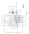
- Figure 1 is a schematic elevation assembly view of the device;
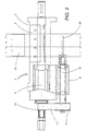
- Figure 2 is a top plan view of the device illustrated in Figure 1.
- With reference to the accompanying drawings, the
numeral 1 indicates as a whole a device for positioninggeneric products 6 in succession, equally spaced on aconveyor belt 2, partially illustrated in the drawings. - The
device 1 basically comprises a first and asecond rotor conveyor belt 2 and driven in phase with one another by a drive comprising aflexible element 11, such as a toothed belt looped around a pair ofpulleys rotors - The
first rotor 3 rotates about a fixed horizontal axis ofrotation 4 and has aradial pusher 5 which, when thefirst rotor 3 rotates, intercepts the back of eachproduct 6 which is individually fed upstream of thedevice 1. Eachproduct 6, when intercepted by thepusher 5, is accelerated along aproduct 6 feed line 7 towards theconveyor belt 2. Thesecond rotor 8 rotates about a fixed axis ofrotation 9 parallel with theaxis 4 of thefirst rotor 3 and is equipped with astop 10, consisting of a flat blade which, when thesecond rotor 8 rotates, periodically intercepts theproduct 6 feed line 7. - The
second rotor 8 is located downstream of thefirst rotor 3, above theconveyor belt 2 and rotates in such a way as to impart to the stop 10 a peripheral speed V2 identical to the feed speed V of thebelt 2. Since the peripheral speed of thepusher 5 is greater than the peripheral speed V2 of thestop 10, theproducts 6 accelerated by thefirst rotor 3 and fed at a speed V1 are intercepted by thestop 10, slowed to speed V2 and deposited on thebelt 2 in succession, spaced equally apart and at the same speed V as the belt 2 (see also Figure 2). - In the embodiment of the
device 1 described above, no reference is made to the type ofproducts 6 positioned, which may be of diverse geometric shapes, nor is any reference made to the methods used to feed theproducts 6 towards thedevice 1, which may envisage, for example, feeding theproducts 6 in succession one by one. - If the
radial pusher 5 also comprises a cutter (as illustrated in Figure 1), thedevice 1 may also be used to prepare theproducts 6 upstream of positioning. It is clear that such aradial pusher 5, supplied with a continuous stream of unfinished products, interacting with the feed line 7, could produce sections ofproducts 6 which could then be sent to and positioned on theconveyor belt 2 using methods identical to those previously described. - The above description shows that a
device 1 made according to the present invention fulfils the aims indicated and provides a simple, economical and highly reliable solution which is also compact; it is also very versatile and, therefore, suitable for general use. - The present invention may be subject to numerous variations, all encompassed by the original design concept. Moreover, all parts may be substituted with technically equivalent elements.
Claims (2)
- A device for positioning products (6) in succession and equally spaced on a conveyor belt (2), comprising a first rotor (3), rotating about a fixed axis of rotation (4) and having at least one pusher (5) which, when the first rotor (3) rotates, intercepts the back of each product (6), accelerating the product along a product (6) feed line (7) towards the conveyor belt (2); and a second rotor (8), rotating about a fixed axis of rotation (9) parallel with the axis (4) of the first rotor (3) and having at least one stop (10) which, when the second rotor (8) rotates, intercepts the product feed line (7), said second rotor (8) being located above the conveyor belt (2) and rotating in such a way that, when it intercepts the feed line (7), it causes the stop or stops (10) to rotate at a peripheral speed (V2) identical to the belt (2) feed speed (V), said stop or stops (10) on the second rotor (8) intercepting the products (6) accelerated by the first rotor (3) , slowing them and depositing them on the belt (2) in succession and spaced equally apart; characterized in that the axis of rotation (4) of the first rotor (3) is located at a side of the axis of rotation (9) of the second rotor (8) above the conveyor belt (2) and the first and the second rotor (3, 8) are driven in phase with one another by a drive comprising a flexible element (11) looped around a pair of pulleys (12, 13), respectively connecting the rotors (3, 8).
- The device according to claim 1, characterised in that the pusher (5) comprises a cutter which, when the first rotor (3) rotates, separates a product (6) from an uninterrupted row of products (6) fed upstream of the pusher (5).
Applications Claiming Priority (2)
| Application Number | Priority Date | Filing Date | Title |
|---|---|---|---|
| IT98BO000205A IT1299942B1 (en) | 1998-03-27 | 1998-03-27 | DEVICE FOR POSITIONING EQUID-SPACED PRODUCTS IN SUCCESSION ON A CONVEYOR BELT. |
| ITBO980205 | 1998-03-27 |
Publications (3)
| Publication Number | Publication Date |
|---|---|
| EP0945375A2 EP0945375A2 (en) | 1999-09-29 |
| EP0945375A3 EP0945375A3 (en) | 2000-08-23 |
| EP0945375B1 true EP0945375B1 (en) | 2002-10-30 |
Family
ID=11343076
Family Applications (1)
| Application Number | Title | Priority Date | Filing Date |
|---|---|---|---|
| EP99830156A Expired - Lifetime EP0945375B1 (en) | 1998-03-27 | 1999-03-19 | A device for positioning products in succession and spaced equally apart on a conveyor belt |
Country Status (7)
| Country | Link |
|---|---|
| US (1) | US6102189A (en) |
| EP (1) | EP0945375B1 (en) |
| AR (1) | AR015741A1 (en) |
| DE (1) | DE69903684T2 (en) |
| ES (1) | ES2185301T3 (en) |
| IT (1) | IT1299942B1 (en) |
| TW (1) | TW409110B (en) |
Families Citing this family (1)
| Publication number | Priority date | Publication date | Assignee | Title |
|---|---|---|---|---|
| US6877740B2 (en) | 2003-07-30 | 2005-04-12 | C.G. Bretting Manufacturing Company, Inc. | Starwheel feed apparatus and method |
Family Cites Families (6)
| Publication number | Priority date | Publication date | Assignee | Title |
|---|---|---|---|---|
| US2991869A (en) * | 1957-03-27 | 1961-07-11 | Baker Perkins Ltd | Apparatus for handling flat articles |
| DE1761913C3 (en) * | 1968-07-20 | 1975-02-27 | Industrie-Werke Karlsruhe Augsburg Ag, 7500 Karlsruhe | Device for feeding and inserting individual pieces that cannot be accumulated in the receiving pockets of a continuously rotating conveyor chain of a cartoning machine |
| GB1336602A (en) * | 1970-01-29 | 1973-11-07 | Molins Ltd | Conveying apparatus |
| CH621529A5 (en) * | 1977-09-05 | 1981-02-13 | Sig Schweiz Industrieges | |
| NL174031C (en) * | 1978-09-14 | 1984-04-16 | Tevopharm Schiedam Bv | Apparatus for the conveying between objects of a towed conveyor of objects which are conveyed continuously in a continuous row. |
| DE3840005A1 (en) * | 1988-11-26 | 1990-05-31 | Komi Koppelberg & Migl Kg Masc | Method and device for testing hollow glass bodies for contained inclusions |
-
1998
- 1998-03-27 IT IT98BO000205A patent/IT1299942B1/en active IP Right Grant
-
1999
- 1999-03-18 US US09/271,937 patent/US6102189A/en not_active Expired - Fee Related
- 1999-03-19 DE DE69903684T patent/DE69903684T2/en not_active Expired - Fee Related
- 1999-03-19 ES ES99830156T patent/ES2185301T3/en not_active Expired - Lifetime
- 1999-03-19 EP EP99830156A patent/EP0945375B1/en not_active Expired - Lifetime
- 1999-03-23 TW TW088104604A patent/TW409110B/en not_active IP Right Cessation
- 1999-03-26 AR ARP990101376A patent/AR015741A1/en unknown
Also Published As
| Publication number | Publication date |
|---|---|
| DE69903684T2 (en) | 2003-06-26 |
| ITBO980205A1 (en) | 1999-09-27 |
| EP0945375A2 (en) | 1999-09-29 |
| ITBO980205A0 (en) | 1998-03-27 |
| US6102189A (en) | 2000-08-15 |
| DE69903684D1 (en) | 2002-12-05 |
| EP0945375A3 (en) | 2000-08-23 |
| TW409110B (en) | 2000-10-21 |
| ES2185301T3 (en) | 2003-04-16 |
| AR015741A1 (en) | 2001-05-16 |
| IT1299942B1 (en) | 2000-04-04 |
Similar Documents
| Publication | Publication Date | Title |
|---|---|---|
| CA2330353C (en) | Device for constructing successive article packs including means of transferring the articles | |
| US8281918B2 (en) | Unit for transferring products | |
| US5188212A (en) | Rotating transport apparatus | |
| US6551228B1 (en) | High speed quarterfolder | |
| US5113996A (en) | Rotary multiple point discharge conveyer | |
| EP2285715B1 (en) | Device for the treatment of article flows and method therefor | |
| EP0711719B1 (en) | Equally spaced product conveying method and line | |
| US11027868B2 (en) | Method for handling food portions with a rotation device | |
| GB2297955A (en) | Product conveyor line | |
| US6106219A (en) | Stack forming and conveying apparatus | |
| AU692928B2 (en) | Packaging machine with metering wheels | |
| EP0819637B1 (en) | Device for turning an editorial product on a packaging line | |
| JPH05193610A (en) | Article loading device, particularly for automatic packing machine | |
| EP1136400B1 (en) | Device for forming groups of articles in a conveyor system, for instance for automatic packaging installations | |
| US8281554B2 (en) | Machine for wrapping sticks of food products | |
| JPH0692434A (en) | Device to carry article transferred in irregular arrangement linearly and at regular interval | |
| US6102189A (en) | Device for positioning products in succession and spaced equally apart on a conveyor belt | |
| EP1268140B1 (en) | Severing machine for articles of weblike material and the like having multiple blades with unloading into parallel channels | |
| US6044627A (en) | Device for conveying plastic pots in the transverse direction at high speed | |
| CA2270215A1 (en) | Carton blank transport apparatus | |
| HUE026257T2 (en) | Feeding system | |
| GB1432371A (en) | Collation of articles | |
| WO1995018053A1 (en) | Lane distribution apparatus | |
| CN215324953U (en) | Device for conveying objects | |
| EP1033336B1 (en) | Conveying device for forming and conveying groups of products |
Legal Events
| Date | Code | Title | Description |
|---|---|---|---|
| PUAI | Public reference made under article 153(3) epc to a published international application that has entered the european phase |
Free format text: ORIGINAL CODE: 0009012 |
|
| AK | Designated contracting states |
Kind code of ref document: A2 Designated state(s): CH DE ES FR GB IT LI NL |
|
| AX | Request for extension of the european patent |
Free format text: AL;LT;LV;MK;RO;SI |
|
| PUAL | Search report despatched |
Free format text: ORIGINAL CODE: 0009013 |
|
| AK | Designated contracting states |
Kind code of ref document: A3 Designated state(s): AT BE CH CY DE DK ES FI FR GB GR IE IT LI LU MC NL PT SE |
|
| AX | Request for extension of the european patent |
Free format text: AL;LT;LV;MK;RO;SI |
|
| RIC1 | Information provided on ipc code assigned before grant |
Free format text: 7B 65G 47/29 A, 7B 65G 47/32 B |
|
| 17P | Request for examination filed |
Effective date: 20001109 |
|
| 17Q | First examination report despatched |
Effective date: 20001228 |
|
| AKX | Designation fees paid |
Free format text: CH DE ES FR GB IT LI NL |
|
| GRAG | Despatch of communication of intention to grant |
Free format text: ORIGINAL CODE: EPIDOS AGRA |
|
| GRAG | Despatch of communication of intention to grant |
Free format text: ORIGINAL CODE: EPIDOS AGRA |
|
| GRAH | Despatch of communication of intention to grant a patent |
Free format text: ORIGINAL CODE: EPIDOS IGRA |
|
| GRAH | Despatch of communication of intention to grant a patent |
Free format text: ORIGINAL CODE: EPIDOS IGRA |
|
| GRAA | (expected) grant |
Free format text: ORIGINAL CODE: 0009210 |
|
| AK | Designated contracting states |
Kind code of ref document: B1 Designated state(s): CH DE ES FR GB IT LI NL |
|
| PG25 | Lapsed in a contracting state [announced via postgrant information from national office to epo] |
Ref country code: NL Free format text: LAPSE BECAUSE OF FAILURE TO SUBMIT A TRANSLATION OF THE DESCRIPTION OR TO PAY THE FEE WITHIN THE PRESCRIBED TIME-LIMIT Effective date: 20021030 Ref country code: FR Free format text: LAPSE BECAUSE OF FAILURE TO SUBMIT A TRANSLATION OF THE DESCRIPTION OR TO PAY THE FEE WITHIN THE PRESCRIBED TIME-LIMIT Effective date: 20021030 |
|
| REG | Reference to a national code |
Ref country code: GB Ref legal event code: FG4D |
|
| REG | Reference to a national code |
Ref country code: CH Ref legal event code: EP |
|
| REF | Corresponds to: |
Ref document number: 69903684 Country of ref document: DE Date of ref document: 20021205 |
|
| REG | Reference to a national code |
Ref country code: CH Ref legal event code: NV Representative=s name: BUGNION S.A. |
|
| NLV1 | Nl: lapsed or annulled due to failure to fulfill the requirements of art. 29p and 29m of the patents act | ||
| REG | Reference to a national code |
Ref country code: ES Ref legal event code: FG2A Ref document number: 2185301 Country of ref document: ES Kind code of ref document: T3 |
|
| EN | Fr: translation not filed | ||
| PLBE | No opposition filed within time limit |
Free format text: ORIGINAL CODE: 0009261 |
|
| STAA | Information on the status of an ep patent application or granted ep patent |
Free format text: STATUS: NO OPPOSITION FILED WITHIN TIME LIMIT |
|
| 26N | No opposition filed |
Effective date: 20030731 |
|
| PGFP | Annual fee paid to national office [announced via postgrant information from national office to epo] |
Ref country code: GB Payment date: 20040317 Year of fee payment: 6 Ref country code: CH Payment date: 20040317 Year of fee payment: 6 |
|
| PGFP | Annual fee paid to national office [announced via postgrant information from national office to epo] |
Ref country code: ES Payment date: 20040318 Year of fee payment: 6 |
|
| PGFP | Annual fee paid to national office [announced via postgrant information from national office to epo] |
Ref country code: DE Payment date: 20040401 Year of fee payment: 6 |
|
| PG25 | Lapsed in a contracting state [announced via postgrant information from national office to epo] |
Ref country code: GB Free format text: LAPSE BECAUSE OF NON-PAYMENT OF DUE FEES Effective date: 20050319 |
|
| PG25 | Lapsed in a contracting state [announced via postgrant information from national office to epo] |
Ref country code: ES Free format text: LAPSE BECAUSE OF NON-PAYMENT OF DUE FEES Effective date: 20050321 |
|
| PG25 | Lapsed in a contracting state [announced via postgrant information from national office to epo] |
Ref country code: LI Free format text: LAPSE BECAUSE OF NON-PAYMENT OF DUE FEES Effective date: 20050331 Ref country code: CH Free format text: LAPSE BECAUSE OF NON-PAYMENT OF DUE FEES Effective date: 20050331 |
|
| PG25 | Lapsed in a contracting state [announced via postgrant information from national office to epo] |
Ref country code: DE Free format text: LAPSE BECAUSE OF NON-PAYMENT OF DUE FEES Effective date: 20051001 |
|
| REG | Reference to a national code |
Ref country code: CH Ref legal event code: PL |
|
| GBPC | Gb: european patent ceased through non-payment of renewal fee |
Effective date: 20050319 |
|
| PGFP | Annual fee paid to national office [announced via postgrant information from national office to epo] |
Ref country code: IT Payment date: 20060331 Year of fee payment: 8 |
|
| REG | Reference to a national code |
Ref country code: ES Ref legal event code: FD2A Effective date: 20050321 |
|
| PG25 | Lapsed in a contracting state [announced via postgrant information from national office to epo] |
Ref country code: IT Free format text: LAPSE BECAUSE OF NON-PAYMENT OF DUE FEES Effective date: 20070319 |