EP0944790B1 - Apparatus for cooling an axle assembly - Google Patents
Apparatus for cooling an axle assembly Download PDFInfo
- Publication number
- EP0944790B1 EP0944790B1 EP97949641A EP97949641A EP0944790B1 EP 0944790 B1 EP0944790 B1 EP 0944790B1 EP 97949641 A EP97949641 A EP 97949641A EP 97949641 A EP97949641 A EP 97949641A EP 0944790 B1 EP0944790 B1 EP 0944790B1
- Authority
- EP
- European Patent Office
- Prior art keywords
- fluid
- inflow
- housing
- outflow
- tubes
- Prior art date
- Legal status (The legal status is an assumption and is not a legal conclusion. Google has not performed a legal analysis and makes no representation as to the accuracy of the status listed.)
- Expired - Lifetime
Links
- 238000001816 cooling Methods 0.000 title claims description 17
- 239000012530 fluid Substances 0.000 claims description 106
- 238000004891 communication Methods 0.000 claims description 10
- 230000005540 biological transmission Effects 0.000 description 4
- 238000012986 modification Methods 0.000 description 3
- 230000004048 modification Effects 0.000 description 3
- 239000003921 oil Substances 0.000 description 3
- 239000012809 cooling fluid Substances 0.000 description 2
- 239000000314 lubricant Substances 0.000 description 2
- 238000005192 partition Methods 0.000 description 2
- 238000012546 transfer Methods 0.000 description 2
- 238000013459 approach Methods 0.000 description 1
- 230000000712 assembly Effects 0.000 description 1
- 238000000429 assembly Methods 0.000 description 1
- 230000009286 beneficial effect Effects 0.000 description 1
- 230000001419 dependent effect Effects 0.000 description 1
- 238000010438 heat treatment Methods 0.000 description 1
- 239000010720 hydraulic oil Substances 0.000 description 1
- 238000000034 method Methods 0.000 description 1
- 230000002035 prolonged effect Effects 0.000 description 1
- 238000005086 pumping Methods 0.000 description 1
Images


Classifications
-
- F—MECHANICAL ENGINEERING; LIGHTING; HEATING; WEAPONS; BLASTING
- F16—ENGINEERING ELEMENTS AND UNITS; GENERAL MEASURES FOR PRODUCING AND MAINTAINING EFFECTIVE FUNCTIONING OF MACHINES OR INSTALLATIONS; THERMAL INSULATION IN GENERAL
- F16H—GEARING
- F16H57/00—General details of gearing
- F16H57/04—Features relating to lubrication or cooling or heating
- F16H57/0412—Cooling or heating; Control of temperature
-
- F—MECHANICAL ENGINEERING; LIGHTING; HEATING; WEAPONS; BLASTING
- F28—HEAT EXCHANGE IN GENERAL
- F28D—HEAT-EXCHANGE APPARATUS, NOT PROVIDED FOR IN ANOTHER SUBCLASS, IN WHICH THE HEAT-EXCHANGE MEDIA DO NOT COME INTO DIRECT CONTACT
- F28D7/00—Heat-exchange apparatus having stationary tubular conduit assemblies for both heat-exchange media, the media being in contact with different sides of a conduit wall
- F28D7/005—Heat-exchange apparatus having stationary tubular conduit assemblies for both heat-exchange media, the media being in contact with different sides of a conduit wall the conduits for only one medium being tubes having bent portions or being assembled from bent tubes or being tubes having a toroidal configuration
Definitions
- the present invention relates generally to an axle assembly, and more particularly to an apparatus and method for cooling an axle assembly.
- Earth working machines such as front end loaders and the like, typically include a frame attached to a body portion.
- An axle assembly is generally secured to the frame.
- the axle assembly includes a housing having chamber defined therein.
- the housing includes a left end and a right end.
- the left end of the housing is attached to a left axle housing.
- the right end of the housing is attached to a right axle housing.
- a left rim mount is secured to the left axle housing such that the left axle housing is interposed between the housing and the left rim mount.
- a right rim mount is secured to the right axle housing such that the right axle housing is interposed between the housing and the right rim mount.
- Tires are secured on the left and right rim mounts such that the machine can roll over the ground.
- the axle assembly includes a differential assembly which is located within the chamber of the housing.
- the axle assembly also includes a braking assembly located within the chamber of the housing.
- the differential assembly is mechanically coupled to an engine via a drive shaft.
- the differential assembly is also mechanically coupled to the left and right rim mounts such that torque generated by the engine is transmitted to the left and right rim mounts via the drive shaft and the differential assembly. Such transmission of torque causes the left and right rim mounts, and therefore the tires, to rotate and propel the machine over the ground to perform various work functions.
- a fluid such as oil
- This fluid cools the differential assembly and the braking assembly.
- the fluid in the chamber can also heat up beyond an acceptable limit.
- the fluid must be cooled to function effectively and prolong the life of the axle assembly.
- U. S. Patent 4,198,819 discloses a cooling mechanism for a power transmission utilized to drive chains of a conveyor belt.
- the mechanism includes a plurality of conduits that circulate cooling fluid through serially arranged components. The conduits run through a heat exchanger to cool the fluid being circulated through the components.
- the mechanism also includes a framework of tubes that are disposed about the housing of the power transmission in a circular array. The tubes have cooling fins disposed in a spiral configuration about the outer surface to "air cool" the fluid in the tubes.
- the tubes however are not immersed in another fluid and the power transmission is intended for use in a permanent location were size constraints are not a major consideration.
- U. S. Patent 4,633,938 discloses a cooling system for a gear drive that includes a pair of tubes that extend through the reservoir of lubricant for the gear drive. A source of cooling fluid passes through the tubes to cool the lubricant in the reservoir.
- the tubes are straight in configuration and the gear drive is not configured for a spaced limited environment.
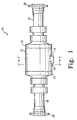
- the axle assembly 10 includes a housing 12, a left axle housing 18 and a right axle housing 22.
- the axle assembly 10 also includes a left rim mount 20 and a right rim mount 24.
- Housing 12 includes a hood portion 14, a flange 16, a first end 13 and a second end 15. An end of right axle housing 22 is secured to first end 13 of housing 12. Right rim mount 24 is secured to right axle housing 22 such that right axle housing 22 is interposed between right rim mount 24 and housing 12. An end of left axle housing 18 is secured to second end 15 of housing 12. Left rim mount 20 is secured to left axle housing 18 such that left axle housing 18 is interposed between left rim mount 20 and housing 12.
- housing 12 also includes a mounting member 28 attached thereto. Housing 12 also includes a drive shaft opening 30 and a first axle opening 32 defined therein. It should be understood that housing 12 has a second axle opening defined therein which is not shown in FIG. 2. Housing 12 further includes a chamber 26 defined therein. The housing 12 defines an interior wall 27 having a shoulder 34 formed thereon. Housing 12 also has attached thereto a port plate 85. Port plate 85 is secured to hood portion 14 with bolts 90. Port plate 85 has an inflow opening 86 and an outflow opening 88 defined therein.
- a differential assembly 36 is mounted within chamber 26 of housing 12 in a well known manner.
- Differential assembly 36 includes an axle mount 38 and a drive gear mount 40.
- Axle mount 38 is coaxially positioned relative to drive gear mount 40. Note that a drive gear which is securable to drive gear mount 40 has been removed from FIG. 2 for clarity of description.
- a first fluid is contained in the reservoir formed by the interior of the axle assembly 10 so as to form a pool therein.
- the pool in chamber 26 has a surface that is represented by line 84.
- Chamber 26 has a conduit assembly 42 positioned therein.
- conduit assembly 42 includes an inflow conduit 50, an outflow conduit 54, a coupler 58 and an exchange container 72.
- Inflow conduit 50 includes a plurality of inflow tubes 52.
- Outflow conduit 54 includes a plurality of outflow tubes 56.
- each inflow tube 52 has an end 98 and an end 102.
- Each inflow tube 52 also has a first passageway 100 defined between end 98 and end 102.
- Each outflow tube 56 has an end 104 and an end 107.
- Each outflow tube 56 has a second passageway 106 defined between end 104 and end 107.
- coupler 58 has an enclosure 60, a frame 62 and a plate 68.
- Enclosure 60 has an inflow aperture 64 and an outflow aperture 66 defined therein.
- Enclosure 60 is secured to frame 62.
- Frame 62 is attached to plate 68 with bolts 70.
- Enclosure 60 also includes a partition member 92 that separates enclosure 60 into a fluid tight first receptacle 94 and a fluid tight second receptacle 96. The partition 92 is positioned such that inflow aperture 64 opens into receptacle 94 and outflow aperture 66 opens into receptacle 96.
- exchange container 72 includes a base plate 74, a cover plate 76 and a wall 108.
- Cover plate 76 is secured to base plate 74 by screwing bolts 78 through cover plate 76 and into bolt holes 112 formed in base plate 74. Securing cover plate 76 to base plate 74 in the above described fashion forms a fluid tight cavity 110 within exchange container 72.
- each inflow tube 52 is secured to plate 68 such that each first end 98 of each first passageway 100 opens into first receptacle 94.
- fourth end 107 of each outflow tube 56 is secured to plate 68 such that each fourth end 107 of each second passageway 106 opens into second receptacle 96.
- each inflow tube 52 is secured to base plate 74 such that each second end 102 of each first passageway 100 opens into cavity 110.
- third end 104 of each outflow tube 56 is secured to base plate 74 such that each third end 104 of each second passageway 106 opens into cavity 110.
- Conduit assembly 42 further includes a number of brackets 44 having a securement member 46 as shown in FIGS. 2 and 3. Securement member 46 has a bolt hole 47 formed therein. Brackets 44 surround and support inflow tubes 52 and outflow tubes 56 of conduit assembly 42. As shown in FIG. 6, inflow tubes 52 are supported by brackets 44 such that a space 115 is defined between adjacent inflow tubes 52. It should be understood that brackets 44 support outflow tubes 56 such that a space (not shown) similar to space 115 is defined between adjacent outflow tubes 56. Space 115 and the space between adjacent outflow tubes 56 are occupied by the first fluid which is contained within the housing 12 of the axle assembly 10. Having space 115 and the space between adjacent outflow tubes 56 occupied by the first fluid facilitates heat transfer between the first fluid and inflow tubes 52 and outflow tubes 56.
- conduit assembly 42 and brackets 44 are positioned within chamber 26 such that bolt hole 47 formed in each securement member 46 aligns with a bolt hole (not shown) formed in shoulder 34.
- a bolt 48 is positioned in bolt hole 47 and screwed into the bolt hole formed in shoulder 34, thus mounting conduit assembly 42 in chamber 26.
- conduit assembly 42 is mounted in chamber 26 such that it partially surrounds differential assembly 36, and is partially submerged in the first fluid pool.
- Conduit assembly 42 is also mounted in chamber 26 such that a space 45 is defined between inner wall 27 and conduit assembly 42.
- Conduit assembly 42 is further mounted in chamber 26 such that inflow aperture 64 (see FIG. 3) is aligned with inflow opening 86 of hood plate 85.
- Conduit assembly 42 is also mounted in chamber 26 such that outflow aperture 66 (see FIG. 3) is aligned with outflow opening 88 of hood plate 85.
- conduit assembly 42 is in fluid communication with a fluid source or fluid pump 124.
- a fluid source or fluid pump 124 is coupled to a reservoir 126 via a fluid line 132
- an outlet port 124b of the fluid pump 124 is coupled to an inlet port 128a of a heat exchanger 128 via a fluid line 130.
- An outlet port 128b of the heat exchanger 128 is coupled to the inflow aperture 64 via a fluid inflow line 120.
- the heat exchanger 128 removes heat from the second fluid, such as hydraulic oil, as the second fluid advances therethrough. Hence, the second fluid is cooled prior to being advanced in the general direction of arrow 80 to the inflow aperture 64.
- the outlet aperture 66 is coupled to the reservoir 126 via a drain line 122. Hence, exhausted or spent fluid may be advanced from conduit assembly 42 to reservoir 126 and hence the fluid pump 124 for subsequent use thereof.
- a pressure relief, or unloading valve 134 is in fluid communication with the conduit assembly 42.
- an inlet of the pressure relief valve 134 is coupled to the fluid line 130 via a fluid line 136
- an outlet of the pressure relief valve 134 is coupled to the drain line 122 via a drain line 138.
- the pressure relief valve 134 includes a fluid pressure sensing line 140 and a spring 142. If a fluid pressure of a predetermined magnitude is exerted on the pressure sensing line 140, the bias of the spring 142 is overcome thereby urging the pressure relief valve 134 downwardly (as viewed in relation to the schematic of FIG. 3).
- fluid pump 124 is a pump that is already present on the machine.
- a hydraulic pump used in a hydraulic steering system or a hydraulic brake system can be easily modified so that the hydraulic system can be connected to the fluid line 130.
- Utilizing a fluid pump 124 which is already present on the machine is beneficial since the number of fluid pumps used by the machine should be kept to as small a number as possible.
- inflow line 120 An end of inflow line 120, opposite to the end connected to the heat exchanger 128, is connected to coupler 58 such that inflow line 120 is in fluid communication with inflow aperture 64.
- An end of the drain line 122 opposite to the end connected to the reservoir 126, is connected to the coupler 58 such that drain line 122 is in fluid communication with outflow aperture 66.
- the above described arrangement places the fluid pump 124 and the reservoir 126 in fluid communication with the conduit assembly 42.
- the second fluid is propelled through fluid inflow line 120 by fluid pump 124 in the direction indicated by arrow 80.
- the second fluid enters first receptacle 94 (see FIG. 4) of coupler 58 through inflow opening 86 (see FIG. 2) and inflow aperture 64.
- the second fluid is advanced through inflow conduit 50 via first passageways 100 of inflow tubes 52 in the direction indicated by arrows 114.
- the second fluid then exits passageways 100 and enters cavity 110 (see FIG. 5) of exchange container 72 (see FIG. 5).
- Once in cavity 110 the second fluid enters outflow conduit 54 via second passageways 106 of outflow tubes 56 as indicated by arrows 116 of FIG. 5.
- the second fluid is then advanced through outflow conduit 54 in the direction of arrows 118.
- the second fluid then exits passageways 106 and enters second receptacle 96 (see FIG. 4) of coupler 58.
- the second fluid exits receptacle 96, via outflow aperture 66 and outflow opening 88 (see FIG. 2), and is advanced through outflow pipe 122 in the direction of arrow 82 back to reservoir 126.
- the second fluid is then recirculated through conduit assembly 42 by fluid pump 124 in the above described manner. It should be understood that the first fluid does not intermix with the second fluid at any time.
- first passageway 100 and second passageway 106 can contain a mechanism having a helically shaped wire to increase the turbulence of the flow of the second fluid through first passageway 100 and second passageway 106. This mechanism functions to improve the rate of heat transfer into the second fluid as is well known in the art.
- the second fluid is shown being cooled by the heat exchange upon exiting the fluid source 124, it should be understood that the second fluid may alternatively be cooled by the heat exchanger after exiting the conduit assembly 42 and prior to entering the reservoir 126.
Landscapes
- Engineering & Computer Science (AREA)
- General Engineering & Computer Science (AREA)
- Mechanical Engineering (AREA)
- Physics & Mathematics (AREA)
- Thermal Sciences (AREA)
- General Details Of Gearings (AREA)
Description
Claims (6)
- An apparatus for cooling an axle assembly, comprising:a housing (12) defining a chamber (26) having a first fluid contained therein;a differential assembly (36) positioned in said chamber (26);a plurality of cooling tubes (42) including a plurality of inflow tubes (52, a plurality of outflow tubes (56), an exchange container (72) connected between the respective inflow and outflow tubes to communicate fluid therebetween and a coupler adapted for fluid communication with each of the inflow and outflow tubes, said cooling tubes being positioned about the differential assembly (36) in a manner wherein at least a portion of the cooling tubes (42) is positioned within the fluid contained in the chamber (26) defined by the housing (12);a fluid source in fluid communication with said coupler, wherein a second fluid, propelled by said fluid source, is advanced through said plurality of cooling tubes (42), and said first fluid located within said housing (12) does not intermix with said second fluid which is being advanced through said plurality of cooling tubes (42).
- The apparatus of claim 1, wherein:said housing (12) includes an inflow opening (86) and an outflow opening (88),said coupler (58) includes-an inflow aperture (64) and an outflow aperture (66),said inflow aperture (64) of said coupler (58) is in fluid communication with said inflow opening (86) of said housing (12), andsaid outflow aperture (66) of said coupler (58) is in fluid communication with said outflow opening (88) of said housing (12).
- The apparatus of claim 1, wherein:a first inflow tube and a second inflow tube of said plurality of inflow tubes (52) define a first space (115) therebetween which is occupied by said first fluid; anda first outflow tube and a second outflow tube of said plurality of outflow tubes (56) define a second space therebetween which is occupied by said first fluid.
- The apparatus of claim 1, wherein said fluid source is positioned outside of said chamber (12).
- The apparatus of claim 1, wherein said first fluid includes oil; andsaid second fluid includes oil.
- The apparatus of claim 1, wherein:a space (45) is defined between said conduit (42) and an interior wall (27) of said housing (12).
Applications Claiming Priority (3)
| Application Number | Priority Date | Filing Date | Title |
|---|---|---|---|
| US76991996A | 1996-12-19 | 1996-12-19 | |
| US769919 | 1996-12-19 | ||
| PCT/US1997/021721 WO1998027367A1 (en) | 1996-12-19 | 1997-11-20 | Apparatus and method for cooling an axle assembly |
Publications (2)
| Publication Number | Publication Date |
|---|---|
| EP0944790A1 EP0944790A1 (en) | 1999-09-29 |
| EP0944790B1 true EP0944790B1 (en) | 2002-10-02 |
Family
ID=25086911
Family Applications (1)
| Application Number | Title | Priority Date | Filing Date |
|---|---|---|---|
| EP97949641A Expired - Lifetime EP0944790B1 (en) | 1996-12-19 | 1997-11-20 | Apparatus for cooling an axle assembly |
Country Status (4)
| Country | Link |
|---|---|
| EP (1) | EP0944790B1 (en) |
| JP (1) | JP4135987B2 (en) |
| DE (1) | DE69716118T2 (en) |
| WO (1) | WO1998027367A1 (en) |
Families Citing this family (3)
| Publication number | Priority date | Publication date | Assignee | Title |
|---|---|---|---|---|
| US5931218A (en) * | 1996-12-19 | 1999-08-03 | Caterpillar Inc. | Apparatus and method for cooling an axle assembly |
| JP4285819B2 (en) * | 1998-03-27 | 2009-06-24 | キャタピラー インコーポレイテッド | Mechanical cooling system |
| DE102006008857A1 (en) | 2006-02-25 | 2007-09-20 | Modine Manufacturing Co., Racine | Heat exchanger and manufacturing process |
Family Cites Families (9)
| Publication number | Priority date | Publication date | Assignee | Title |
|---|---|---|---|---|
| DE2148819C3 (en) * | 1971-09-30 | 1982-02-25 | Gewerkschaft Eisenhütte Westfalia, 4670 Lünen | Cooling device for a gear arrangement, in particular for driving extraction and conveying devices for mining |
| AU3706078A (en) * | 1977-06-14 | 1979-12-20 | Dowty Meco Ltd | Liquid cooling of power transmission package |
| US4633938A (en) * | 1985-08-08 | 1987-01-06 | The Falk Corporation | Gear drive cooling system |
| JPH0647171Y2 (en) * | 1989-04-07 | 1994-11-30 | トヨタ自動車株式会社 | Lubricating oil cooling structure of power transmission device |
| JP2516687Y2 (en) * | 1989-12-05 | 1996-11-06 | 東洋ラジエーター株式会社 | Oil cooler for automotive differential gear |
| JPH0517259U (en) * | 1991-08-20 | 1993-03-05 | 栃木富士産業株式会社 | Fluid cooling structure |
| JPH0576845U (en) * | 1992-03-26 | 1993-10-19 | 三菱自動車工業株式会社 | Cooling device for differential lubricating oil |
| FI932094L (en) * | 1993-05-07 | 1994-11-08 | Kone Oy | Crane gearbox cooling device |
| JPH0814368A (en) * | 1994-06-28 | 1996-01-16 | Fuji Heavy Ind Ltd | Oil temperature adjusting device for differential gear |
-
1997
- 1997-11-20 WO PCT/US1997/021721 patent/WO1998027367A1/en not_active Ceased
- 1997-11-20 EP EP97949641A patent/EP0944790B1/en not_active Expired - Lifetime
- 1997-11-20 JP JP52772998A patent/JP4135987B2/en not_active Expired - Fee Related
- 1997-11-20 DE DE69716118T patent/DE69716118T2/en not_active Expired - Fee Related
Also Published As
| Publication number | Publication date |
|---|---|
| JP4135987B2 (en) | 2008-08-20 |
| WO1998027367A1 (en) | 1998-06-25 |
| DE69716118D1 (en) | 2002-11-07 |
| JP2001506354A (en) | 2001-05-15 |
| EP0944790A1 (en) | 1999-09-29 |
| DE69716118T2 (en) | 2003-02-20 |
Similar Documents
| Publication | Publication Date | Title |
|---|---|---|
| US5931218A (en) | Apparatus and method for cooling an axle assembly | |
| US5316106A (en) | Lubricant cooling system for a motor vehicle axle | |
| US6997284B1 (en) | Lubricant cooling system for a motor vehicle axle | |
| US20040154846A1 (en) | Motor-cooling structure of front-and-rear-wheel-drive vehicle | |
| EP1004799B1 (en) | Drive unit with lubricant cooling cover | |
| EP1375970B1 (en) | Power train assembly and method for lubricating such an assembly | |
| US20090050412A1 (en) | External Axle Cooling System | |
| RU2145286C1 (en) | Automobile drive set | |
| RU2158686C2 (en) | Automobile drive unit | |
| EP0944790A1 (en) | Apparatus and method for cooling an axle assembly | |
| RU2148512C1 (en) | Drive unit | |
| HU217057B (en) | Driving unit mainly for motor vehicles | |
| JP2023051178A (en) | Wheel-type construction machine | |
| JPH0610669A (en) | Vehicle cooling system | |
| US5881711A (en) | Viscous heater | |
| CN219866194U (en) | Heat dissipation type speed reducer shell, mining speed reducer and mining crushing equipment | |
| JPH04185263A (en) | Cooling apparatus of wheel motor | |
| EP1046015A1 (en) | Heat exchange means for a vehicle | |
| JPH0763032A (en) | Oil pan device for vehicle engine | |
| CN119664887A (en) | Tractor chassis heat dissipation lubrication system and method | |
| US5881712A (en) | Vehicle heaters | |
| JP3170707B2 (en) | Water pump for water cooling system of engine | |
| JPS5874823A (en) | Water exhaust device of engine cooling water pump | |
| CA2222090A1 (en) | Viscous fluid type heater and method for circulating heat exchange fluid | |
| JPH055317Y2 (en) |
Legal Events
| Date | Code | Title | Description |
|---|---|---|---|
| PUAI | Public reference made under article 153(3) epc to a published international application that has entered the european phase |
Free format text: ORIGINAL CODE: 0009012 |
|
| 17P | Request for examination filed |
Effective date: 19990614 |
|
| AK | Designated contracting states |
Kind code of ref document: A1 Designated state(s): DE FR SE |
|
| 17Q | First examination report despatched |
Effective date: 20001113 |
|
| RTI1 | Title (correction) |
Free format text: APPARATUS FOR COOLING AN AXLE ASSEMBLY |
|
| GRAG | Despatch of communication of intention to grant |
Free format text: ORIGINAL CODE: EPIDOS AGRA |
|
| GRAG | Despatch of communication of intention to grant |
Free format text: ORIGINAL CODE: EPIDOS AGRA |
|
| GRAH | Despatch of communication of intention to grant a patent |
Free format text: ORIGINAL CODE: EPIDOS IGRA |
|
| GRAH | Despatch of communication of intention to grant a patent |
Free format text: ORIGINAL CODE: EPIDOS IGRA |
|
| GRAA | (expected) grant |
Free format text: ORIGINAL CODE: 0009210 |
|
| AK | Designated contracting states |
Kind code of ref document: B1 Designated state(s): DE FR SE |
|
| REF | Corresponds to: |
Ref document number: 69716118 Country of ref document: DE Date of ref document: 20021107 |
|
| ET | Fr: translation filed | ||
| PLBE | No opposition filed within time limit |
Free format text: ORIGINAL CODE: 0009261 |
|
| STAA | Information on the status of an ep patent application or granted ep patent |
Free format text: STATUS: NO OPPOSITION FILED WITHIN TIME LIMIT |
|
| 26N | No opposition filed |
Effective date: 20030703 |
|
| PGFP | Annual fee paid to national office [announced via postgrant information from national office to epo] |
Ref country code: SE Payment date: 20071105 Year of fee payment: 11 |
|
| PGFP | Annual fee paid to national office [announced via postgrant information from national office to epo] |
Ref country code: FR Payment date: 20071105 Year of fee payment: 11 |
|
| PGFP | Annual fee paid to national office [announced via postgrant information from national office to epo] |
Ref country code: DE Payment date: 20081128 Year of fee payment: 12 |
|
| EUG | Se: european patent has lapsed | ||
| REG | Reference to a national code |
Ref country code: FR Ref legal event code: ST Effective date: 20090731 |
|
| PG25 | Lapsed in a contracting state [announced via postgrant information from national office to epo] |
Ref country code: SE Free format text: LAPSE BECAUSE OF NON-PAYMENT OF DUE FEES Effective date: 20081121 |
|
| PG25 | Lapsed in a contracting state [announced via postgrant information from national office to epo] |
Ref country code: DE Free format text: LAPSE BECAUSE OF NON-PAYMENT OF DUE FEES Effective date: 20100601 |
|
| PG25 | Lapsed in a contracting state [announced via postgrant information from national office to epo] |
Ref country code: FR Free format text: LAPSE BECAUSE OF NON-PAYMENT OF DUE FEES Effective date: 20081130 |