EP0944523B1 - A composite tip cap assembly for a helicopter main rotor blade - Google Patents
A composite tip cap assembly for a helicopter main rotor blade Download PDFInfo
- Publication number
- EP0944523B1 EP0944523B1 EP97953046A EP97953046A EP0944523B1 EP 0944523 B1 EP0944523 B1 EP 0944523B1 EP 97953046 A EP97953046 A EP 97953046A EP 97953046 A EP97953046 A EP 97953046A EP 0944523 B1 EP0944523 B1 EP 0944523B1
- Authority
- EP
- European Patent Office
- Prior art keywords
- composite
- plies
- tip cap
- woven plies
- fairing
- Prior art date
- Legal status (The legal status is an assumption and is not a legal conclusion. Google has not performed a legal analysis and makes no representation as to the accuracy of the status listed.)
- Expired - Lifetime
Links
- 239000002131 composite material Substances 0.000 title claims description 206
- 239000000835 fiber Substances 0.000 claims description 41
- 238000005299 abrasion Methods 0.000 claims description 18
- OKTJSMMVPCPJKN-UHFFFAOYSA-N Carbon Chemical compound [C] OKTJSMMVPCPJKN-UHFFFAOYSA-N 0.000 claims description 14
- 229910002804 graphite Inorganic materials 0.000 claims description 14
- 239000010439 graphite Substances 0.000 claims description 14
- XAGFODPZIPBFFR-UHFFFAOYSA-N aluminium Chemical compound [Al] XAGFODPZIPBFFR-UHFFFAOYSA-N 0.000 description 16
- 229910052782 aluminium Inorganic materials 0.000 description 16
- 230000000712 assembly Effects 0.000 description 16
- 238000000429 assembly Methods 0.000 description 16
- 230000010354 integration Effects 0.000 description 13
- 238000004519 manufacturing process Methods 0.000 description 11
- 238000000465 moulding Methods 0.000 description 11
- PXHVJJICTQNCMI-UHFFFAOYSA-N Nickel Chemical compound [Ni] PXHVJJICTQNCMI-UHFFFAOYSA-N 0.000 description 10
- 229910001220 stainless steel Inorganic materials 0.000 description 10
- 239000010935 stainless steel Substances 0.000 description 9
- 238000000034 method Methods 0.000 description 8
- JFLRKDZMHNBDQS-UCQUSYKYSA-N CC[C@H]1CCC[C@@H]([C@H](C(=O)C2=C[C@H]3[C@@H]4C[C@@H](C[C@H]4C(=C[C@H]3[C@@H]2CC(=O)O1)C)O[C@H]5[C@@H]([C@@H]([C@H]([C@@H](O5)C)OC)OC)OC)C)O[C@H]6CC[C@@H]([C@H](O6)C)N(C)C.CC[C@H]1CCC[C@@H]([C@H](C(=O)C2=C[C@H]3[C@@H]4C[C@@H](C[C@H]4C=C[C@H]3C2CC(=O)O1)O[C@H]5[C@@H]([C@@H]([C@H]([C@@H](O5)C)OC)OC)OC)C)O[C@H]6CC[C@@H]([C@H](O6)C)N(C)C Chemical compound CC[C@H]1CCC[C@@H]([C@H](C(=O)C2=C[C@H]3[C@@H]4C[C@@H](C[C@H]4C(=C[C@H]3[C@@H]2CC(=O)O1)C)O[C@H]5[C@@H]([C@@H]([C@H]([C@@H](O5)C)OC)OC)OC)C)O[C@H]6CC[C@@H]([C@H](O6)C)N(C)C.CC[C@H]1CCC[C@@H]([C@H](C(=O)C2=C[C@H]3[C@@H]4C[C@@H](C[C@H]4C=C[C@H]3C2CC(=O)O1)O[C@H]5[C@@H]([C@@H]([C@H]([C@@H](O5)C)OC)OC)OC)C)O[C@H]6CC[C@@H]([C@H](O6)C)N(C)C JFLRKDZMHNBDQS-UCQUSYKYSA-N 0.000 description 6
- RYGMFSIKBFXOCR-UHFFFAOYSA-N Copper Chemical compound [Cu] RYGMFSIKBFXOCR-UHFFFAOYSA-N 0.000 description 6
- 239000000853 adhesive Substances 0.000 description 6
- 230000001070 adhesive effect Effects 0.000 description 6
- 239000010949 copper Substances 0.000 description 6
- 229910052802 copper Inorganic materials 0.000 description 6
- 239000000463 material Substances 0.000 description 6
- 230000000295 complement effect Effects 0.000 description 5
- 229910052759 nickel Inorganic materials 0.000 description 5
- 229920000271 Kevlar® Polymers 0.000 description 4
- 239000000470 constituent Substances 0.000 description 4
- 239000011159 matrix material Substances 0.000 description 4
- 239000011347 resin Substances 0.000 description 4
- 229920005989 resin Polymers 0.000 description 4
- RTAQQCXQSZGOHL-UHFFFAOYSA-N Titanium Chemical compound [Ti] RTAQQCXQSZGOHL-UHFFFAOYSA-N 0.000 description 3
- 239000007769 metal material Substances 0.000 description 3
- 230000008569 process Effects 0.000 description 3
- 239000010936 titanium Substances 0.000 description 3
- 229910052719 titanium Inorganic materials 0.000 description 3
- 239000004593 Epoxy Substances 0.000 description 2
- 229920003235 aromatic polyamide Polymers 0.000 description 2
- 238000005452 bending Methods 0.000 description 2
- -1 e.g. Substances 0.000 description 2
- 239000011152 fibreglass Substances 0.000 description 2
- 230000013011 mating Effects 0.000 description 2
- 230000009467 reduction Effects 0.000 description 2
- BCCGKQFZUUQSEX-WBPXWQEISA-N (2r,3r)-2,3-dihydroxybutanedioic acid;3,4-dimethyl-2-phenylmorpholine Chemical compound OC(=O)[C@H](O)[C@@H](O)C(O)=O.OC(=O)[C@H](O)[C@@H](O)C(O)=O.O1CCN(C)C(C)C1C1=CC=CC=C1 BCCGKQFZUUQSEX-WBPXWQEISA-N 0.000 description 1
- ZOXJGFHDIHLPTG-UHFFFAOYSA-N Boron Chemical compound [B] ZOXJGFHDIHLPTG-UHFFFAOYSA-N 0.000 description 1
- 239000004760 aramid Substances 0.000 description 1
- 229910052796 boron Inorganic materials 0.000 description 1
- 230000015556 catabolic process Effects 0.000 description 1
- 238000009734 composite fabrication Methods 0.000 description 1
- 238000007796 conventional method Methods 0.000 description 1
- 238000005336 cracking Methods 0.000 description 1
- 230000003247 decreasing effect Effects 0.000 description 1
- 238000006731 degradation reaction Methods 0.000 description 1
- 230000032798 delamination Effects 0.000 description 1
- 239000004744 fabric Substances 0.000 description 1
- 239000002657 fibrous material Substances 0.000 description 1
- 239000007770 graphite material Substances 0.000 description 1
- 239000004761 kevlar Substances 0.000 description 1
- 238000003475 lamination Methods 0.000 description 1
- 239000000203 mixture Substances 0.000 description 1
- 238000005457 optimization Methods 0.000 description 1
- ISWSIDIOOBJBQZ-UHFFFAOYSA-N phenol group Chemical group C1(=CC=CC=C1)O ISWSIDIOOBJBQZ-UHFFFAOYSA-N 0.000 description 1
- 230000002787 reinforcement Effects 0.000 description 1
- 230000008439 repair process Effects 0.000 description 1
- 239000012260 resinous material Substances 0.000 description 1
- 239000003351 stiffener Substances 0.000 description 1
Images






Classifications
-
- B—PERFORMING OPERATIONS; TRANSPORTING
- B64—AIRCRAFT; AVIATION; COSMONAUTICS
- B64C—AEROPLANES; HELICOPTERS
- B64C27/00—Rotorcraft; Rotors peculiar thereto
- B64C27/32—Rotors
- B64C27/46—Blades
-
- B—PERFORMING OPERATIONS; TRANSPORTING
- B64—AIRCRAFT; AVIATION; COSMONAUTICS
- B64C—AEROPLANES; HELICOPTERS
- B64C27/00—Rotorcraft; Rotors peculiar thereto
- B64C27/32—Rotors
- B64C27/46—Blades
- B64C27/463—Blade tips
Definitions
- the present invention relates to helicopter main rotor blades, and more particularly, to a composite tip cap assembly for a helicopter main rotor blade.
- a helicopter main rotor assembly and in particular the main rotor blades thereof, is subjected to a variety of operational forces - aerodynamic, inertial, and centrifugal.
- main rotor blades must be designed to accommodate various dynamic loads such a bending loads, flapwise (out-of-plane) and chordwise (in-plane) loads, axial loads (centrifugal), and torsional loads.
- dynamic loads subject the main rotor blades to varying degrees of stresses/strains.
- the extreme outboard end or tip of the main rotor blade is subjected to the greatest stresses/strains due to aerodynamic forces, and concomitantly experiences the greatest structural degradation due to wear and abrasion (due to the high rotational velocity of the main rotor blade tip), during operation of the helicopter main rotor assembly.
- the extreme outboard end of the main rotor blade has the highest probability of experiencing structural damage as a result of striking external objects.
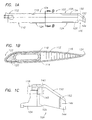
- FIGS 1A-1C illustrate an exemplary main rotor blade 100 for a helicopter as described in U.S. Patent No. 5,542,820.
- the main rotor blade 100 comprises an inboard segment 102 configured for mounting the main rotor blade 100 to the helicopter rotor hub assembly (not shown), an intermediate segment 104, and a replaceable tip segment 106 (reference numeral 105 identifies the demarcation between the outboard end of the intermediate segment 104 and the replaceable tip segment 106).
- the inboard, intermediate, and tip segments 102, 104, 106 in combination define the span of the main rotor blade 100.
- the main rotor blade 100 has a leading edge 108 and a trailing edge 110, which in combination define the chord of the main rotor blade 100.
- the inboard and intermediate regions 102, 104 of the main rotor blade 100 are fabricated from upper and lower composite skins 112, 114 that define the upper and lower aerodynamic surfaces of the blade 100, respectively, a honeycomb core 116, a spar 118, one or more counterweights 120, a leading-edge sheath 122, and adjustable trim tabs 124.
- the upper and lower composite skins 112, 114 are bonded to the honeycomb core 116, which functions as a low weight, structural stiffening member between the composite skins 112, 114.
- the spar 118 is a prefabricated component (either from composite material(s) or a metallic material such as titanium) and functions as the primary structural member of the main rotor blade 100, reacting the torsional, bending, shear, and centrifugal dynamic loads developed in the blade 100 during operation of the helicopter main rotor assembly.
- the leading-edge sheath 122 is a prefabricated hybrid component fabricated from composite materials, e.g., woven fiberglass material embedded in a suitable resin matrix, and abrasion-resistive materials, e.g., titanium and nickel strips.
- the sheath 122 has a generally C-shaped configuration that defines the leading edge 108 of the main rotor blade 100 from the inboard end of the inboard segment 102 to the outboard end of the intermediate segment 104.
- the leading-edge sheath 122, and in particular the abrasion-resistive strips provide abrasion protection for the leading edge 108 of the main rotor blade 100.
- the leading-edge sheath 122 also provides control of airfoil tolerances of the main rotor blade 100.
- the replaceable tip segment 106 of the main rotor blade 106 has a defined aerodynamic configuration, e.g., rearward sweep, taper, and/or anhedral, to enhance the aerodynamic performance of the main rotor blade 100 and the main rotor assembly.
- the replaceable tip segment 106 comprises upper and lower composite skins bonded in combination with a honeycomb core.
- a recess 140 is formed in the honeycomb core of the replaceable tip segment 106, the recess 140 having dimensions slightly greater than the external dimensions of the spar 118.
- the replaceable tip segment 106 is attached to the spar 118 by bonding using an adhesive material such as epoxy film adhesive applied to the wall(s) defining the recess 140 and the external surface of the spar 118.
- fasteners 145 e.g., threaded fasteners, may be used to enhance the attachment of the replaceable tip segment 106 in combination with the intermediate segment 104.
- Replaceable tip segments as described hereinabove are removable at the depot level, which greatly facilitates timely repair or replacement thereof.
- the described embodiment of the main rotor blade 100 further includes a composite tip cap 144, e.g., graphite fibers embedded in a suitable resin matrix, that is secured, e.g., by fasteners 146, in combination with the outboard end of the replaceable tip segment 106.
- the tip cap 144 may be fabricated from a metallic material such as titanium or aluminum.
- the tip cap 144 is replaceable at the field level, which minimizes the time and costs associated with the replacement thereof.
- the replaceable tip segment 106 includes an abrasion strip 150 and the composite tip cap 144 includes an abrasion strip 152.
- the abrasion strips 150, 152 which are typically formed from an abrasive-resistant metallic material such as nickel, in combination define the leading edge of the replaceable tip segment 106.
- the Assignee of the present invention Sikorsky Aircraft Corporation, currently provides replaceable tip cap assemblies for its UH-60 BLACK HAWK® and SH-60 SEAHAWK® (BLACK HAWK and SEAHAWK are registered trademarks of the Sikorsky Aircraft Corporation) helicopters.
- These replaceable tip cap assemblies include a main fairing, internal ribs, a composite closure fairing, and a nickel abrasion strip.
- the main fairing is fabricated from aluminum and has a defined aerodynamic configuration, i.e., upper and lower airfoils having aerodynamic surfaces, a leading edge, and a trailing edge.
- the internal ribs comprise a plurality of aluminum C-shaped members that are disposed within the cavity of the main fairing and secured to the upper and lower airfoils by means of aerospace fasteners.
- the composite closure fairing which has an aerodynamic configuration, is fabricated from a KEVLAR®-based composite material (KEVLAR is a registered trademark of E.I. du Pont de Nemours & Co., Wilmington, DE for an aromatic polyamide fiber of extremely high tensile strength) and bonded in combination with the main fairing using a suitable adhesive.
- the nickel abrasion strip is bonded in combination with the leading edges of the main and closure fairings.
- the aluminum tip cap assembly is bolted in combination with the outboard end of the main rotor blade.
- each of these aluminum tip cap assemblies is comprised of sixteen separate components such that the manufacture and assemblage of these aluminum tip cap assemblies is both time consuming and labor intensive.
- the integration of the individual C-shaped rib members in combination with the main fairing is particularly time consuming and labor intensive, requiring in excess of ninety aerospace fasteners to secure the individual C-shaped rib members in combination with the main fairing.
- the main fairing is susceptible to fatigue cracking as a result of the high aerodynamic loading to which the tip cap assemblies are subjected during operation of the main rotor assembly such that the aluminum tip cap assemblies must be regularly inspected and replaced.
- Such a tip cap assembly should have a design configuration that makes it compatible as a retrofit item for the aluminum tip cap assemblies currently utilized in UH-60 BLACK HAWK® and SH-60 SEAHAWK® helicopters.
- One object of the present invention include providing a composite tip cap assembly for a helicopter main rotor blade that includes a unitary composite rib detail.
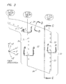
- Figures 2A, 2B are a schematic perspective view and an upper plan view, respectively, of a composite tip cap assembly 10 according to the present invention.
- the composite tip cap assembly 10 has a structural and functional design configuration that makes the composite tip cap assembly 10 a replacement item for the aluminum tip cap assemblies described hereinabove that are currently utilized in the UH-60 BLACK HAWK® and SH-60 SEAHAWK® helicopters manufactured by Sikorsky Aircraft Corporation.
- the composite tip cap assembly 10 comprises a composite main fairing 20, a composite closure fairing 50, a unitary composite rib detail 60, and an abrasion strip 70.
- the composite tip cap assembly 10 has an aerodynamic configuration of a type commonly used on helicopter main rotor blades and such aerodynamic configuration may include any selected combination of rearward sweep, taper, and/or anhedral.
- the explicit aerodynamic configuration of the composite tip cap assembly 10 is not a claimed feature of the present invention, and, therefore, is not described in specific detail.
- the constituent components comprising embodiment of the composite tip cap assembly 10 are fabricated from composite material in the form of composite prepregs.
- Composite prepregs are formed from woven fibrous cloth, yarn, or fiber tow comprised of a matrix of orientated fibrous material such as graphite, aramids, e.g., KEVLAR®, boron, fiberglass or the like, which is impregnated with a predetermined amount of epoxy, phenolic, or other similar organic resinous material.
- the organic resin impregnated composite material is staged to form a "tacky" composite material, i.e., prepreg.
- Composite prepregs in the tacky condition are handled and processed in the various lay-up phases for forming the components of the composite tip cap assembly 10 according to the present invention.
- the composite prepregs are formed of fibrous graphite material embedded in a suitable resin matrix.
- Graphite-based composite materials were selected for the present application inasmuch as such materials possess good strain allowables and a high stiffness-to-weight ratio.
- An exemplary graphite-based composite material having utility for the present invention is IM7G/8552, which is commercially available from Hercules Inc., Wilmington, DE.
- the graphite-based composite prepregs utilized to fabricate the components of the composite tip cap assembly 10 according to the present invention are unidirectional plies (in tape form) and plain weave plies as described hereinbelow in further detail for each component.
- the unidirectional plies have a nominal ply thickness of approximately 0.01524 centimeters (0.006 inches) and the plain weave plies have a nominal ply thickness of about 0.019 centimeters (0.0075 inches).
- the composite main fairing 20 which is illustrated in Figures 3. 3A-3E, is defined by an upper airfoil 22, a lower airfoil 24, a leading edge 26, a trailing edge 28, an inboard integration region 30, and an outboard integration region 32.
- the outer mold line (OML) surfaces of the upper and lower airfoils 22, 24 define the aerodynamic configuration of the composite main fairing 20, and the leading and trailing edges 26, 28 in combination define the chord C L20 (see Figures 3C, 3D) of the composite main fairing 20.
- the inner mold line (IML) surface of the inboard integration region 30 has a configuration that is complementary to the OML surface of the outboard end of a helicopter main rotor blade (not shown).
- the inboard integration region 30 includes a plurality of apertures 31(shown in phantom in Figure 3 - see Figures 2A, 2B) that are used for securing (by bolted connections) the composite tip cap assembly 10 in combination with the outboard end of the helicopter main rotor blade.
- the OML surface of the outboard integration region 32 has a configuration that is complementary to the composite closure fairing 50.
- the outboard integration region 32 may optionally include a plurality of alignment apertures 33 (shown in phantom in Figures 2B, 3) for aligning the outboard end of the unitary composite rib detail 60 internally within the composite main fairing 20 as discussed in further detail hereinbelow.
- the composite main fairing 20 is formed from a plurality of unidirectional plies 34 and a plurality of woven plies 36 in interleaved combination (see Figures 3A, 3B, 3E).
- the unidirectional plies 34 are defined by a single fiber orientation.
- the defining fiber orientation of the unidirectional plies 34 is -20°.
- the plurality of woven plies 36 includes first woven plies 36A having first/second fiber orientations and second woven plies 36B having first/second fiber orientations.
- the first woven plies 36A have fiber orientations of -20°/+70°
- the second woven plies 36B have fiber orientations of -65°/+25°.
- the unidirectional plies 34 are used only in the inboardly extending arm region of composite main fairing 20 adjacent the leading edge 26 (see Figure 3E).
- the remainder of the structure of the composite main fairing 20, including the leading edge 26, is formed from an interleaved combination of the first and second woven plies 36A, 36B.
- fabricating the composite main fairing 20 from a graphite-based composite material minimizes the incidence of fatigue cracks in the composite main fairing 20 due to the excellent strength of a graphite-based composite material and its ability to transfer vibratory loads.
- a composite main fairing 20 fabricated from graphite-based composite material exhibits superior resistance to crack propagation.
- the interleaved first and second woven plies 36A, 36B forming the upper and lower airfoils 22, 24 of the composite main fairing 20 are configured to provide IML chamfered shoulders 40, 41 (see Figures 3B, 3E).
- the IML chamfered shoulders 40, 41 are operative to ensure precise mating of the composite main fairing 20 of the composite tip cap assembly 10 in combination with the outboard end of the helicopter main rotor blade.
- interleaved first and second woven plies 36A, 36B forming the upper and lower airfoils 22, 24 of the composite main fairing 20 are configured to provide OML chamfered shoulders 42, 43 (see Figure 3A) that are operative to facilitate mating of the composite main fairing 20 in combination with the composite closure fairing 50.
- interleaved first and second woven plies 36A, 36B forming the upper and lower airfoils 22, 24 of the composite main fairing 20 are configured to provide IML chamfered shoulders 44, 45 as illustrated in Figure 3A.
- the IML chamfered shoulders 44, 45 are operative to facilitate proper positioning of the unitary rib detail 60 internally within the composite main fairing 20.
- the described embodiment of the composite main fairing 20 further includes plies 47A, 47B of stainless steel mesh wherein the stainless steel mesh plies 47A have a strand orientation of -20° and the stainless steel mesh plies 47B have a strand orientation of 90° (see Figures 3B, 3E, and 4).
- the stainless steel mesh plies 47A, 47B are an AMS5690 Plain Dutch 50X250 stainless steel wire mesh (available from Gerard Daniel & Co., New Rochelle, NY).
- the composite main fairing 20 may include plies 48 of copper mesh (see Figures 3B, 4).
- a copper mesh such as FM99M-029CXMC, available from Cytec Engineered Materials, Havre de Grace, MD, may be used for the copper mesh plies 48.
- the unidirectional plies 34 and the first and second woven plies 36A, 36B (as well as the stainless steel plies 47A, 47B, and the copper mesh plies 48, if incorporated) comprising the upper and lower airfoils 22, 24 are assembled in interleaved combination in separate lay-ups 22L, 24L as exemplarily illustrated in Figure 4.
- the upper and lower airfoil lay-ups 22L, 24L are assembled in a molding assembly, which, for the described embodiment, is a split mold assembly SM consisting of an adjustable mold half SM1 and a fixed mold half SM2.
- the adjustable mold half SM1 is movable with respect to the fixed mold half SM2 to facilitate assemblage of the upper and lower airfoil lay-ups 22L, 24L in the split mold assembly SM.
- the first and second woven plies 36A, 36B comprising the leading edge 26 of the composite main fairing 20 are overlapped to form a splice joint in the leading edge 26.
- An intensifier is added to the splice joint to ensure proper lamination of the first and second woven plies 36A, 36B forming the leading edge 26.
- fabricating the composite main fairing 20 utilizing upper and lower airfoil lay-ups 22L, 24L greatly simplifies the fabrication process, and in addition, optimizes the structural integrity of the composite tip cap assembly 10. Optimization of structural integrity is achieved by forming the splice joint in the leading edge 26 of the composite main fairing 20.
- any splice joint in a composite structure is a structurally weak region that is subject to delamination. In the present circumstances, however, structural integrity of the leading edge 26 is maintained since the abrasion strip 70 that is subsequently bonded to OML surface of the leading edge 26, i.e., the abrasion strip 70 overlays the splice joint, provides structural reinforcement, i.e., structural strength, in the leading edge 26 of the composite tip cap assembly 10.
- the split mold assembly SM with the upper and lower airfoil lay-ups 22L, 24L assembly therein as described immediately hereinabove, is subsequently vacuum bagged and cured in an autoclave using conventional techniques and procedures known to those skilled in the art to form a precured composite main fairing 20.
- Cure cycle parameters e.g., temperature, pressure, time, depend in large part on the constituent elements of the composite material and are known to those skilled in the art.
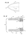
- the composite closure fairing 50 which is illustrated in Figures 6A-6D, is similar in design configuration to the closure fairing described hereinabove for the aluminum tip cap assemblies.
- the composite closure fairing 50 is defined by an upper airfoil 51, a lower airfoil 52, a leading edge 53, a trailing edge 54, and an inboard integration region 55.
- the OML surfaces of the upper and lower airfoils 51, 52 define the aerodynamic configuration of the composite closure fairing 50, and the leading, trailing edges 53, 54 in combination define the chord C L50 (see Figure 6C, 6D) of the composite closure fairing 50.
- the inner mold line (IML) surface of the inboard integration region 55 has a configuration that is complementary to the outboard integration region 32 of the composite main fairing 20.
- the composite closure fairing 50 is formed as a unitary structure from a first plurality of woven plies 56 and a second plurality of woven plies 57 in interleaved combination (see Figure 6D).
- the first plurality of woven plies 56 includes first woven plies 56A defined by a single fiber orientation and second woven plies 56B defined by a single fiber orientation.
- the fiber orientation of the first woven plies 56A is +45°
- the fiber orientation of the second woven plies 56B is -45°.
- the second plurality of woven plies 57 have first/second fiber orientations.
- the woven plies 57 have fiber orientations of 0°/90°.
- the composite closure fairing 50 is fabricated from graphite-based composite material as described hereinabove. In addition to the advantages of graphite-based composite material as discussed hereinabove, the fabrication process for the composite closure fairing 50 is enhanced due to the improved pliability and lower cost of graphite-based composite material (as opposed to the use of a KEVLAR®-based composite material for the composite closure fairing of the aluminum tip cap assemblies described hereinabove).
- the described embodiment of the composite closure fairing 50 further includes stainless steel mesh plies 58 having a strand orientation of -20° (see Figures 6B, 6D).
- the composition and configuration of the stainless steel mesh plies 58 are similar to the stainless steel mesh plies 47A, 47B described hereinabove for the composite main fairing 20.
- the composite closure fairing 50 may include plies 59 of copper mesh (see Figures 6A, 6B) of the type described hereinabove with respect to the composite main fairing 20.
- the first and second woven plies 56A, 56B, and the woven plies 57 (as well as the stainless steel mesh plies 58, and the copper mesh plies 59, if incorporated) comprising the composite closure fairing 50 are layed-up in interleaved combination in a conventional molding assembly (not shown), typically a female molding assembly.
- the layed-up molding assembly is subsequently vacuum bagged and subjected to an autoclave cure to form a precured composite closure fairing 50.
- cure cycle parameters such as temperature, pressure, time, which depend in large part on the constituent elements of the composite material, are well known to those skilled in the art.
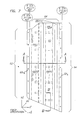
- the unitary composite rib detail 60 which is exemplarily illustrated in Figures 7, 7A-7C, has a design dimensions such that the unitary composite rib detail 60 is complementary to the IML surfaces of the composite main fairing 20.
- the unitary composite rib detail 60 is defined by an inboard interface region 62, an outboard interface region 64, and an intermediate corrugated region 66.
- the inboard interface region 62 comprises upper and lower flanges 62U, 62L having OML surfaces that abuttingly engage the IML surfaces of the upper and lower airfoils 22, 24 of the composite main fairing 20 as shown in Figure 7A.
- the outboard interface region 64 comprises a flange that has an OML surface that abuttingly engages the inner mold line surface of the lower airfoil 24 of the composite main fairing 20.
- the unitary composite rib detail 60 is positioned internally within the composite main fairing 20 and is operative to provide structural bridging support between the upper and lower airfoils 22, 24.
- the intermediate corrugated region 66 comprises transverse webs 66T and upper and lower lateral webs 66UL, 66LL that provide continuity between the transverse webs 66T (see Figures 7, 7A).
- the lower lateral webs 66LL are fabricated to include spaced apart rib stiffeners 66RS (see Figure 7, 7A) to provide additional structural strength for the intermediate corrugated region 66 of the unitary composite web detail 60.
- the transverse webs 66T of the intermediate corrugated region 66 are dimensioned so that the OML surfaces of the upper and lower lateral webs 66UL, 66LL abuttingly engage the IML surfaces of the upper and lower airfoils 22, 24, respectively, of the composite main fairing 20.
- the unitary composite rib detail 60 is formed from a plurality of woven plies 68.
- the plurality of woven plies 68 includes first woven plies 68A having first/second fiber orientations and second woven plies 68B having first/second fiber orientations.
- first woven plies 68A have fiber orientations of ⁇ 45° and the second woven plies 68B have fiber orientations of 0°/90°.
- the first and second woven plies 68A, 68B comprising the unitary composite rib detail 60 are layed-up in interleaved combination in a conventional molding assembly such as the multi-component molding assembly MA exemplarily illustrated in Figure 8.
- the molding assembly MA illustrated in Figure 8 utilizes a laserply locator LPL to ensure that each first and second woven ply 68A, 68B is properly positioned in the molding assembly MA.
- the relative simplicity of the configuration of the unitary composite rib detail 60 according to the present invention facilitates the use of a multi-component molding assembly MA so that a plurality of unitary composite rib details 60 may be fabricated simultaneously, thereby decreasing the per unit cost of the rib details 60.
- the layed-up molding assembly MA is subsequently vacuum bagged and subjected to an autoclave cure to form a precured unitary composite rib detail 60.
- cure cycle parameters such as temperature, pressure, time, which depend in large part on the constituent elements of the composite material, are well known to those skilled in the art.
- the upper and lower flanges 62U, 62L defining the inboard interface region 62 of the unitary composite rib detail 60 are fabricated as integral extensions of the inboardmost transverse web 66Ti (see Figure 7A).
- the lower flange may be fabricated as a separate element and integrated in combination with the inboardmost transverse web.
- Figures 9A-9C illustrate a lower flange 62L' fabricated as a separate element that comprises a tranverse leg 63T and a lateral leg 63L.
- the lower flange 62L' is comprised of first and second woven plies 68A, 68B as described hereinabove that are layed-up in a conventional mold in abutting combination with the inboardmost transverse web, vacuum bagged, and autoclave cured using conventional composite fabrication techniques and cure cycle parameters such as pressure, temperature, and time, to form a cured lower flange 62L' that is an integral element of the unitary composite rib detail 60.
- the design configuration of the unitary composite rib detail 60 facilitates the integration of balance weights in combination with the composite tip cap assembly 10 to statically and dynamically balance the composite tip cap assembly 10.
- one or more nutplates 90 i.e., a plate with a captured nut, are bonded in combination with the inboardmost transverse web 66Ti.
- Balance weights 92 are then secured to the inboardmost transverse web 66Ti by means of attachment screws 94 that thread into the respective nutplates 90.
- the abrasion strip 70 is exemplarily illustrated in Figures 2A, 2B and is similar in configuration and material to the abrasion strips currently used in the aluminum tip cap assemblies described hereinabove for the UH-60 BLACK HAWK® and SH-60 SEAHAWK® helicopters.
- the IML surface of the abrasion strip 70 is complementary to the OML surfaces of the leading edges 26, 53 of the composite main and closure fairings 20, 50, respectively.
- the abrasion strip 70 is preferably fabricated from nickel, which has superior abrasion-resistance characteristics for helicopter applications, using any conventional fabrication technique.
- the cured unitary composite rib detail 60 is first integrated in combination with the cured composite main fairing 20 by bonding with a suitable high temperature adhesive of a type known to those skilled in the art (such a high temperature adhesive typically cures at a temperature of about 250°F).
- a suitable high temperature adhesive typically cures at a temperature of about 250°F.
- Proper positioning of the cured unitary composite rib detail 60 in combination with the composite main fairing 20 is achieved by the abutting engagement of the OML surface of the outboard interface flange 64 with the IML surface of the outboard integration region 32 of the lower airfoil 24 of cured composite main fairing 20.
- alignment apertures 62LA, 64A may be formed in one or both of the respective interface flanges 62L, 64 of the unitary composite rib detail 60 as illustrated in Figure 7.
- Corresponding alignment apertures would be formed in the lower airfoil 22 of the composite main fairing 20 (only the corresponding alignment apertures 33 are illustrated - see Figure 3), and alignment pins inserted through such alignment apertures to properly position the unitary composite rib detail 60 internally within the composite main fairing 20. While the use of alignment pins as described immediately hereinabove makes the fabrication process more complex, it will be appreciated that the optional use of alignment pins to properly position the unitary composite rib detail 60 in combination with the composite main fairing 20 is by far less labor intensive than the fabrication of the aluminum tip cap assembly described hereinabove.
- Each C-shaped rib member of the prior art aluminum tip cap assembly must be positioned using alignment pins.
- alignment pins are only required for one or both of the respective interface flanges 62L, 64 of the unitary composite rib detail 60. After the unitary composite rib detail 60 has been bonded in combination with the composite main fairing 20 the alignment pins are removed.
- the composite closure fairing 50 is bonded in combination with the outboard integration region 32 of the composite main fairing using a suitable high temperature adhesive of the a type known to those skilled in the art.
- the abrasion strip 70 is bonded in combination with the leading edges 26, 63 of the composite main and closure fairings 20, 60, respectively, using a suitable high temperature of a type known to those skilled in the art.
- the composite tip cap assembly 10 comprises only four primary components (in contrast to the aluminum tip cap assemblies for the UH-60 BLACK HAWK® and SH-60 SEAHAWK® helicopters described hereinabove which have sixteen primary components), thereby simplifying both the manufacture and assemblage of the composite tip cap assembly 10.
- the simplification in the manufacturing and assemblage of the composite tip cap assembly 10 results in a significant reduction in the per unit cost of the composite tip cap assembly 10 as compared to the prior art tip cap assemblies described above (a per unit cost reduction of close to fifty percent (50%) is achieved).
Landscapes
- Engineering & Computer Science (AREA)
- Mechanical Engineering (AREA)
- Aviation & Aerospace Engineering (AREA)
- Moulding By Coating Moulds (AREA)
- Structures Of Non-Positive Displacement Pumps (AREA)
- Turbine Rotor Nozzle Sealing (AREA)
- Laminated Bodies (AREA)
Description
Claims (11)
- A composite tip cap assembly (10) for a helicopter main rotor blade (100), the composite tip cap (10) including an abrasion strip (70) the composite tip cap (10) being characterized by:a composite main fairing (20), a unitary rib detail (60), a composite closure fairing (50) integrated in combination with said composite main fairing (20),the abrasion strip (70) being integrated in combination with said composite main fairing (20) and said composite closure fairing (50),said composite main fairing (20) including a plurality of unidirectional plies (34) having a fiber orientation, and a plurality of woven plies (36) including first woven plies (36A) having first/second fiber orientations and second woven plies (36B) having first/second fiber orientations, said plurality of unidirectional plies (34), said first woven plies (36A), and said second woven plies (36B) being interleaved in combination to form said composite main fairing (20); andsaid unitary composite rib detail (60) being internally integrated in combination with said composite main fairing (20).
- The composite tip cap assembly of claim 1 wherein: said fiber orientation of said unidirectional plies (34) is -20°; said first/second fiber orientations of said first woven plies (36A) are -20°/+70°; and said first/second fiber orientations of said second woven plies (36B) are -65°/-25°.
- The composite tip cap assembly of claim 1 or 2 wherein said plurality of unidirectional plies (34) and said plurality of woven plies (36) are graphite-based composite prepregs.
- The composite tip cap assembly of any of claims 1 to 3 wherein said unitary composite rib detail (60) comprises:an inboard interface region (62);an outboard interface region (64); anda corrugated region (66) intermediate and contiguous with said inboard and outboard interface regions.
- The composite tip cap assembly of claim 4 wherein said intermediate corrugated region (66) comprises a plurality of transverse webs (66T) and a plurality of upper and lower lateral webs (66UL, 66LL) contiguous with said transverse webs, wherein said inboard interface region (62) comprises upper and lower flanges (62U, 62L) contiguous with and extending inboardly from said inboardmost transverse web, and wherein said outboard interface region (64) comprises a lower flange contiguous with and extending outboardly from said outboardmost transverse web.
- The composite tip cap assembly of any of claims 1 to 5 wherein said unitary composite rib detail (60) comprises a plurality of woven plies (68) including first woven plies (68A) having first/second fiber orientations and second woven plies (6SB) having first second fiber orientations, said first woven plies and said second woven plies being interleaved in combination to form said unitary composite rib detail.
- The composite tip cap assembly of claim 6 wherein said first/second fiber orientations of said first woven plies (68A) are ±45° and wherein said first/second fiber orientations of said second woven plies (68B) are 0°/90°.
- The composite tip cap assembly of claim 6 or 7 wherein said plurality of woven plies (68) are graphite-based composite prepregs.
- The composite tip cap assembly of any of claims 1 to 8 wherein said composite closure fairing (50) comprises:a first plurality of woven plies (56) including first woven plies (56A) defined by a single fiber orientation and second woven plies (56B) defined by a single fiber orientation; anda second plurality of woven plies (57) having first/second fiber orientations;said first and second pluralities of woven plies being interleaved in combination to form said composite closure fairing.
- The composite tip cap assembly of claim 9 wherein said defining fiber orientation of said first woven plies (56A) is ±45°, said defining fiber orientation of said second woven plies (56B) is -45°, and said first/second fiber orientations of said second plurality of woven plies (57) are 0°/90°.
- The composite tip cap assembly of claim 9 or 10 wherein said first and second pluralities of woven plies (56, 57) are graphite-based composite prepregs.
Applications Claiming Priority (3)
| Application Number | Priority Date | Filing Date | Title |
|---|---|---|---|
| US772680 | 1996-12-23 | ||
| US08/772,680 US5885059A (en) | 1996-12-23 | 1996-12-23 | Composite tip cap assembly for a helicopter main rotor blade |
| PCT/US1997/021492 WO1998028186A1 (en) | 1996-12-23 | 1997-11-21 | A composite tip cap assembly for a helicopter main rotor blade |
Publications (2)
| Publication Number | Publication Date |
|---|---|
| EP0944523A1 EP0944523A1 (en) | 1999-09-29 |
| EP0944523B1 true EP0944523B1 (en) | 2000-10-25 |
Family
ID=25095850
Family Applications (1)
| Application Number | Title | Priority Date | Filing Date |
|---|---|---|---|
| EP97953046A Expired - Lifetime EP0944523B1 (en) | 1996-12-23 | 1997-11-21 | A composite tip cap assembly for a helicopter main rotor blade |
Country Status (7)
| Country | Link |
|---|---|
| US (1) | US5885059A (en) |
| EP (1) | EP0944523B1 (en) |
| JP (1) | JP4015703B2 (en) |
| KR (1) | KR100468508B1 (en) |
| CN (1) | CN1084695C (en) |
| AU (1) | AU5687398A (en) |
| WO (1) | WO1998028186A1 (en) |
Families Citing this family (32)
| Publication number | Priority date | Publication date | Assignee | Title |
|---|---|---|---|---|
| FR2741590B1 (en) * | 1995-11-29 | 1998-01-30 | Eurocopter France | BLADE WITH REINFORCED PROTECTION AGAINST LIGHTNING, FOR ROTOR OF A GIRAVION |
| RU2229422C2 (en) * | 2001-10-01 | 2004-05-27 | Орловский государственный технический университет | Helicopter main rotor |
| US6976829B2 (en) * | 2003-07-16 | 2005-12-20 | Sikorsky Aircraft Corporation | Rotor blade tip section |
| US7246998B2 (en) * | 2004-11-18 | 2007-07-24 | Sikorsky Aircraft Corporation | Mission replaceable rotor blade tip section |
| US7621480B2 (en) * | 2005-05-26 | 2009-11-24 | Sikorsky Aircraft Corporation | De-rotation system for a counter-rotating, coaxial rotor hub shaft fairing |
| US7607607B2 (en) * | 2005-05-26 | 2009-10-27 | Sikorsky Aircraft Corporation | De-rotation system suitable for use with a shaft fairing system |
| US7229251B2 (en) * | 2005-05-31 | 2007-06-12 | Sikorsky Aircraft Corporation | Rotor hub fairing system for a counter-rotating, coaxial rotor system |
| DE102006031491B4 (en) * | 2005-07-19 | 2010-09-30 | Eurocopter Deutschland Gmbh | Method for producing a three-dimensionally curved fiber composite structural component |
| EP2118494B1 (en) | 2007-03-01 | 2019-05-01 | Delta T, LLC | Angled airfoil extension for fan blade |
| EP2227641B1 (en) * | 2007-12-03 | 2016-07-20 | Sikorsky Aircraft Corporation | Magnetic de-rotation system for a shaft fairing system |
| US7762785B2 (en) * | 2007-12-10 | 2010-07-27 | Sikorsky Aircraft Corporation | Main rotor blade with integral tip section |
| EP2238018A2 (en) | 2008-01-02 | 2010-10-13 | Sikorsky Aircraft Corporation | Planetary de-rotation system for a shaft fairing system |
| US8262344B2 (en) * | 2008-04-02 | 2012-09-11 | Hamilton Sundstrand Corporation | Thermal management system for a gas turbine engine |
| US8353673B2 (en) * | 2008-04-26 | 2013-01-15 | Sikorsky Aircraft Corporation | Main rotor blade with integral cuff |
| EP2253803B1 (en) * | 2009-05-21 | 2018-12-12 | Rolls-Royce plc | Composite aerofoil blade with wear-resistant tip and corresponding method |
| US10137542B2 (en) | 2010-01-14 | 2018-11-27 | Senvion Gmbh | Wind turbine rotor blade components and machine for making same |
| BR112012017122B1 (en) | 2010-01-14 | 2021-09-28 | Senvion Gmbh | COMPOSITE BEAM FOR A WIND TURBINE SHOVEL |
| FR2968237B1 (en) * | 2010-12-03 | 2017-03-10 | Eurocopter France | IMPROVED PROCESS FOR MANUFACTURING REINFORCED PIECES OF COMPOSITE MATERIALS AND REINFORCED PIECES OBTAINED THEREBY |
| US9168998B2 (en) * | 2011-11-23 | 2015-10-27 | The Boeing Company | Composite propeller spar |
| US8842000B2 (en) | 2012-07-17 | 2014-09-23 | 4Front Engineered Solutions, Inc. | Fire control systems |
| US11261735B2 (en) | 2013-03-07 | 2022-03-01 | Textron Innovations Inc. | Removable rotor blade tip |
| US10167075B2 (en) * | 2013-06-25 | 2019-01-01 | The Boeing Company | Joint assembly and method of forming thereof |
| US9874214B2 (en) | 2014-01-28 | 2018-01-23 | 4Front Engineered Solutions, Inc. | Fan with fan blade mounting structure |
| EP3142923B1 (en) | 2014-05-15 | 2020-05-06 | Sikorsky Aircraft Corporation | Metallic dimpled doubler |
| US9726192B2 (en) | 2015-03-31 | 2017-08-08 | Assa Abloy Entrance Systems Ab | Fan blades and associated blade tips |
| CN107453018B (en) * | 2016-05-31 | 2021-03-09 | 洛阳尖端技术研究院 | Metamaterial antenna and forming method thereof |
| CN108045557A (en) * | 2017-12-15 | 2018-05-18 | 惠阳航空螺旋桨有限责任公司 | A kind of spinner |
| CN109502050B (en) * | 2018-12-12 | 2024-04-02 | 山东智翼航空科技有限公司 | Unmanned aerial vehicle rotor overall static balance and bidirectional dynamic balance test system |
| US11498671B2 (en) | 2019-05-13 | 2022-11-15 | Lockheed Martin Corporation | Replacement tip section for a rotor blade and method of replacing a rotor blade tip section |
| US11046420B2 (en) * | 2019-10-23 | 2021-06-29 | The Boeing Company | Trailing edge flap having a waffle grid interior structure |
| CN113290966B (en) * | 2021-05-21 | 2022-10-18 | 山东中恒景新碳纤维科技发展有限公司 | Multilayer woven fiber composite material and application thereof, ski shell and preparation method thereof |
| CN113942643A (en) * | 2021-10-09 | 2022-01-18 | 中国直升机设计研究所 | Composite material blade with replaceable blade tip |
Family Cites Families (17)
| Publication number | Priority date | Publication date | Assignee | Title |
|---|---|---|---|---|
| US2866616A (en) * | 1951-03-02 | 1958-12-30 | Stalker Dev Company | Fabricated bladed structures for axial flow machines |
| US2884078A (en) * | 1953-10-21 | 1959-04-28 | Parsons Corp | Rotor blade structure having spanwise reinforcing members |
| US3095180A (en) * | 1959-03-05 | 1963-06-25 | Stalker Corp | Blades for compressors, turbines and the like |
| US3528753A (en) * | 1968-06-14 | 1970-09-15 | United Aircraft Corp | Helicopter blade with non-homogeneous structural spar |
| US3721507A (en) * | 1971-09-22 | 1973-03-20 | United Aircraft Corp | Blade for high speed helicopter |
| US3782856A (en) * | 1972-05-31 | 1974-01-01 | United Aircraft Corp | Composite aerodynamic blade with twin-beam spar |
| FR2195255A5 (en) * | 1972-08-04 | 1974-03-01 | Snecma | |
| US4120610A (en) * | 1974-05-16 | 1978-10-17 | Textron, Inc. | Helicopter blade structure |
| US3999888A (en) * | 1975-06-25 | 1976-12-28 | United Technologies Corporation | Composite tip weight attachment |
| US4022547A (en) * | 1975-10-02 | 1977-05-10 | General Electric Company | Composite blade employing biased layup |
| US4051289A (en) * | 1976-04-12 | 1977-09-27 | General Electric Company | Composite airfoil construction |
| US4324530A (en) * | 1980-01-21 | 1982-04-13 | United Technologies Corp. | Helicopter blade with a tip having a selected combination of sweep, taper and anhedral to improve hover efficiency |
| GB2154286A (en) * | 1984-02-13 | 1985-09-04 | Gen Electric | Hollow laminated airfoil |
| US4621980A (en) * | 1984-09-19 | 1986-11-11 | United Technologies Corporation | Fiber reinforced composite spar for a rotary wing aircraft |
| US5129787A (en) * | 1991-02-13 | 1992-07-14 | United Technologies Corporation | Lightweight propulsor blade with internal spars and rigid base members |
| US5320494A (en) * | 1992-12-22 | 1994-06-14 | United Technologies Corporation | Helicopter rotor blade having a replaceable anhedral tip |
| US5542820A (en) * | 1994-12-23 | 1996-08-06 | United Technologies Corporation | Engineered ceramic components for the leading edge of a helicopter rotor blade |
-
1996
- 1996-12-23 US US08/772,680 patent/US5885059A/en not_active Expired - Lifetime
-
1997
- 1997-11-21 AU AU56873/98A patent/AU5687398A/en not_active Abandoned
- 1997-11-21 KR KR10-1999-7005549A patent/KR100468508B1/en not_active Expired - Fee Related
- 1997-11-21 JP JP52874898A patent/JP4015703B2/en not_active Expired - Fee Related
- 1997-11-21 WO PCT/US1997/021492 patent/WO1998028186A1/en not_active Ceased
- 1997-11-21 CN CN97180959A patent/CN1084695C/en not_active Expired - Fee Related
- 1997-11-21 EP EP97953046A patent/EP0944523B1/en not_active Expired - Lifetime
Also Published As
| Publication number | Publication date |
|---|---|
| US5885059A (en) | 1999-03-23 |
| CN1241974A (en) | 2000-01-19 |
| WO1998028186A1 (en) | 1998-07-02 |
| KR100468508B1 (en) | 2005-01-27 |
| CN1084695C (en) | 2002-05-15 |
| JP2001506952A (en) | 2001-05-29 |
| AU5687398A (en) | 1998-07-17 |
| KR20000057691A (en) | 2000-09-25 |
| EP0944523A1 (en) | 1999-09-29 |
| JP4015703B2 (en) | 2007-11-28 |
Similar Documents
| Publication | Publication Date | Title |
|---|---|---|
| US5885059A (en) | Composite tip cap assembly for a helicopter main rotor blade | |
| EP2703283B1 (en) | Bonded composite aircraft wing | |
| US10836472B2 (en) | One-piece composite bifurcated winglet | |
| US6659722B2 (en) | Composite rotor blade and method of manufacture | |
| EP2636593B1 (en) | Space frame structure | |
| EP3077194B1 (en) | Bonded and tailorable composite assembly | |
| EP3246248B1 (en) | Folding proprotor blade assembly having integral tang assembly | |
| US11161592B2 (en) | Torque box sleeves for aircraft wing assemblies | |
| EP3275783B1 (en) | Rotor blade erosion protection systems | |
| US5645400A (en) | Composite cuff structure for helicopter rotors | |
| AU2664892A (en) | Bearingless main rotor assembly torque tube | |
| EP3013687B1 (en) | Joint assembly and method of forming thereof | |
| US5621967A (en) | Method of making a leading edge weight retention assembly for a helicopter rotor | |
| KR101958948B1 (en) | A monolithic blade, a rotorcraft rotor fitted with such a monolithic blade, and an associated rotorcraft | |
| EP0221678B1 (en) | Helicopter rotor | |
| EP3115296B1 (en) | Rotorcraft rotor blade assembly | |
| US9745056B2 (en) | Main rotor blade with composite integral skin and cuff | |
| US20170370233A1 (en) | Enhanced durability nickel abrasion strip | |
| KR102698326B1 (en) | Rotor for hover-capable aircraft | |
| WO2025036906A1 (en) | Lightning protection in a segmented wind turbine blade |
Legal Events
| Date | Code | Title | Description |
|---|---|---|---|
| PUAI | Public reference made under article 153(3) epc to a published international application that has entered the european phase |
Free format text: ORIGINAL CODE: 0009012 |
|
| 17P | Request for examination filed |
Effective date: 19990615 |
|
| AK | Designated contracting states |
Kind code of ref document: A1 Designated state(s): GB |
|
| GRAG | Despatch of communication of intention to grant |
Free format text: ORIGINAL CODE: EPIDOS AGRA |
|
| 17Q | First examination report despatched |
Effective date: 20000210 |
|
| GRAG | Despatch of communication of intention to grant |
Free format text: ORIGINAL CODE: EPIDOS AGRA |
|
| GRAH | Despatch of communication of intention to grant a patent |
Free format text: ORIGINAL CODE: EPIDOS IGRA |
|
| GRAH | Despatch of communication of intention to grant a patent |
Free format text: ORIGINAL CODE: EPIDOS IGRA |
|
| GRAA | (expected) grant |
Free format text: ORIGINAL CODE: 0009210 |
|
| AK | Designated contracting states |
Kind code of ref document: B1 Designated state(s): GB |
|
| EN | Fr: translation not filed | ||
| PLBE | No opposition filed within time limit |
Free format text: ORIGINAL CODE: 0009261 |
|
| STAA | Information on the status of an ep patent application or granted ep patent |
Free format text: STATUS: NO OPPOSITION FILED WITHIN TIME LIMIT |
|
| 26N | No opposition filed | ||
| REG | Reference to a national code |
Ref country code: GB Ref legal event code: IF02 |
|
| PGFP | Annual fee paid to national office [announced via postgrant information from national office to epo] |
Ref country code: GB Payment date: 20161027 Year of fee payment: 20 |
|
| REG | Reference to a national code |
Ref country code: GB Ref legal event code: PE20 Expiry date: 20171120 |
|
| PG25 | Lapsed in a contracting state [announced via postgrant information from national office to epo] |
Ref country code: GB Free format text: LAPSE BECAUSE OF EXPIRATION OF PROTECTION Effective date: 20171120 |