EP0944351B1 - Reduced-noise catheter - Google Patents
Reduced-noise catheter Download PDFInfo
- Publication number
- EP0944351B1 EP0944351B1 EP97942675A EP97942675A EP0944351B1 EP 0944351 B1 EP0944351 B1 EP 0944351B1 EP 97942675 A EP97942675 A EP 97942675A EP 97942675 A EP97942675 A EP 97942675A EP 0944351 B1 EP0944351 B1 EP 0944351B1
- Authority
- EP
- European Patent Office
- Prior art keywords
- temperature
- catheter
- wires
- sensor
- temperature sensor
- Prior art date
- Legal status (The legal status is an assumption and is not a legal conclusion. Google has not performed a legal analysis and makes no representation as to the accuracy of the status listed.)
- Expired - Lifetime
Links
- 238000010438 heat treatment Methods 0.000 claims description 46
- 238000012545 processing Methods 0.000 claims description 27
- 238000000034 method Methods 0.000 claims description 10
- 230000004913 activation Effects 0.000 claims description 3
- 230000001419 dependent effect Effects 0.000 claims 1
- 230000005672 electromagnetic field Effects 0.000 claims 1
- 230000000747 cardiac effect Effects 0.000 description 24
- 239000008280 blood Substances 0.000 description 13
- 210000004369 blood Anatomy 0.000 description 13
- 230000008878 coupling Effects 0.000 description 13
- 238000010168 coupling process Methods 0.000 description 13
- 238000005859 coupling reaction Methods 0.000 description 13
- 238000005259 measurement Methods 0.000 description 11
- 230000017531 blood circulation Effects 0.000 description 7
- 230000007423 decrease Effects 0.000 description 5
- 210000000748 cardiovascular system Anatomy 0.000 description 4
- 230000004217 heart function Effects 0.000 description 4
- 230000008901 benefit Effects 0.000 description 3
- 238000000576 coating method Methods 0.000 description 3
- 239000004020 conductor Substances 0.000 description 3
- 210000005245 right atrium Anatomy 0.000 description 3
- 210000005241 right ventricle Anatomy 0.000 description 3
- 210000004204 blood vessel Anatomy 0.000 description 2
- 230000008859 change Effects 0.000 description 2
- 230000006870 function Effects 0.000 description 2
- 210000001147 pulmonary artery Anatomy 0.000 description 2
- 230000009467 reduction Effects 0.000 description 2
- 238000001356 surgical procedure Methods 0.000 description 2
- 230000001360 synchronised effect Effects 0.000 description 2
- 230000002792 vascular Effects 0.000 description 2
- 239000000654 additive Substances 0.000 description 1
- 230000000996 additive effect Effects 0.000 description 1
- 230000009084 cardiovascular function Effects 0.000 description 1
- 230000005800 cardiovascular problem Effects 0.000 description 1
- 238000013131 cardiovascular procedure Methods 0.000 description 1
- 239000011248 coating agent Substances 0.000 description 1
- 238000004891 communication Methods 0.000 description 1
- 230000000694 effects Effects 0.000 description 1
- 230000005288 electromagnetic effect Effects 0.000 description 1
- 239000012530 fluid Substances 0.000 description 1
- 230000006872 improvement Effects 0.000 description 1
- 230000001939 inductive effect Effects 0.000 description 1
- 208000014674 injury Diseases 0.000 description 1
- 239000012212 insulator Substances 0.000 description 1
- 238000012986 modification Methods 0.000 description 1
- 230000004048 modification Effects 0.000 description 1
- 230000008569 process Effects 0.000 description 1
- 239000011253 protective coating Substances 0.000 description 1
- 230000001681 protective effect Effects 0.000 description 1
- 210000003102 pulmonary valve Anatomy 0.000 description 1
- 230000005855 radiation Effects 0.000 description 1
- 230000004044 response Effects 0.000 description 1
- 238000012360 testing method Methods 0.000 description 1
- 230000008733 trauma Effects 0.000 description 1
- 210000001631 vena cava inferior Anatomy 0.000 description 1
- 210000002620 vena cava superior Anatomy 0.000 description 1
Images



Classifications
-
- A—HUMAN NECESSITIES
- A61—MEDICAL OR VETERINARY SCIENCE; HYGIENE
- A61B—DIAGNOSIS; SURGERY; IDENTIFICATION
- A61B5/00—Measuring for diagnostic purposes; Identification of persons
- A61B5/02—Detecting, measuring or recording for evaluating the cardiovascular system, e.g. pulse, heart rate, blood pressure or blood flow
- A61B5/026—Measuring blood flow
- A61B5/0275—Measuring blood flow using tracers, e.g. dye dilution
- A61B5/028—Measuring blood flow using tracers, e.g. dye dilution by thermo-dilution
-
- G—PHYSICS
- G01—MEASURING; TESTING
- G01F—MEASURING VOLUME, VOLUME FLOW, MASS FLOW OR LIQUID LEVEL; METERING BY VOLUME
- G01F1/00—Measuring the volume flow or mass flow of fluid or fluent solid material wherein the fluid passes through a meter in a continuous flow
- G01F1/68—Measuring the volume flow or mass flow of fluid or fluent solid material wherein the fluid passes through a meter in a continuous flow by using thermal effects
-
- G—PHYSICS
- G01—MEASURING; TESTING
- G01F—MEASURING VOLUME, VOLUME FLOW, MASS FLOW OR LIQUID LEVEL; METERING BY VOLUME
- G01F1/00—Measuring the volume flow or mass flow of fluid or fluent solid material wherein the fluid passes through a meter in a continuous flow
- G01F1/68—Measuring the volume flow or mass flow of fluid or fluent solid material wherein the fluid passes through a meter in a continuous flow by using thermal effects
- G01F1/684—Structural arrangements; Mounting of elements, e.g. in relation to fluid flow
Definitions
- the present invention relates to catheters for measuring cardiac functions and, more particularly, to catheters which incorporate a temperature sensor for measuring cardiac output.
- Cardiac functions such as intercardiac pressure, flow rate, and ejection fraction of a patient are monitored by physicians in order to obtain vital information necessary to perform various cardiovascular procedures.
- cardiac output provides a physician with the amount of blood discharged from one ventricle of the heart, typically the right ventricle, and flowing through the cardiovascular system at a given time.
- Cardiac output is preferably measured continuously throughout a particular surgical procedure.
- the cardiac output of a patient may also be measured before and after a surgical procedure.
- the physician inserts a catheter into the cardiovascular system and positions the catheter at a target site.
- the catheter has a heating element which is activated to heat the blood flowing around the catheter at the target sight.
- a temperature sensor for example, a thermistor, positioned downstream of the heating element provides a signal from which blood temperature is calculated.
- Cardiac output may then be calculated based upon the blood temperature in conjunction with other variables.
- One such device for the thermal determination of cardiac performance is described in US Patent 3,359,974.
- the signal from the temperature sensor is relatively small. Accordingly, conventional temperature-sensing catheters are vulnerable to a number of error-inducing sources.
- a surgical theater is a particularly noisy electrical environment, due in part to multiple machines operating simultaneously. The human body is also very noisy. All of this electronic, thermal, and physiological noise decreases the accuracy of the signal from the temperature sensor.
- sophisticated signal processing techniques and equipment have been employed in the prior art to reduce the amount of noise (and resultant error) as much as possible, there still exists a significant amount of noise in the measurement of cardiac output. These noise problems affect the accuracy of cardiac output measurements and hinder a physician's ability to successfully diagnose, monitor, and treat cardiovascular problems of a patient.
- thermosensing catheter which mitigates and/or obviates the aforementioned drawbacks of conventional temperature-sensing catheters.
- a catheter includes a body portion having a distal end and a proximal end.
- a plurality of lumens are formed in the body portion between the distal and proximal ends.
- a heating element and a temperature sensor preferably a thermistor, are disposed on the catheter, with the temperature sensor positioned between the heating element and the distal end of the body portion.
- Heating-element wires are connected to the heating element and extend from the heating element to the proximal end of the body portion in one of the lumens of the catheter, and temperature-sensor wires are connected to the temperature sensor and extend in a twisted configuration from the temperature sensor to the proximal end of the body portion in one of the lumens of the catheter.
- the heating-element wires are connectable to a control unit and carry an activation signal from the control unit to the heating element to activate the heating element.
- the temperature-sensor wires are connectable to a processing unit and carry a temperature-sensor signal from the temperature sensor to the processing unit for processing.
- An advantage of the catheter of the present invention over conventional catheters is that the twisted configuration of the temperature-sensor wires significantly reduces the amount of noise and, accordingly, the amount of error in measuring cardiac output.
- the inventors of the present invention have determined that a flow differential of cardiac output, which is the difference between the actual blood flow and the measured blood flow, may be reduced by about 80%. This significant reduction in flow differential provides a greatly improved, highly accurate temperature-sensing catheter for measuring cardiac output.
- the temperature-sensor wires may be received in the same lumen within which the heating-element wires are received.
- heating-element wires induced a significant cross-talk signal onto the temperature-sensor wires. Accordingly, attempts were made to isolate and shield the temperature-sensor wires in another lumen.
- the twisted configuration of the temperature-sensor wires substantially eliminates cross talk from the heating-element wires. Accordingly, the wires may be received within the same catheter. This allows one additional lumen to be used for another purpose, thereby increasing the functionality of the catheter. Alternatively, the catheter may be made with a reduced outer diameter, thereby providing reduced risk of trauma to the cardiovascular system of the patient.
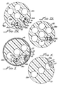
- the reduced-noise catheter 20 generally includes a body portion 22 which has a distal end 24 and a proximal end 26. At least one but preferably a plurality of lumens are formed in the body portion 22 longitudinally between the distal end 24 and the proximal end 26 thereof.
- the lumens are generally indicated by reference numeral 28 and specifically indicated by reference numeral 28 with an alpha suffix, i.e., 28 a , 28 b , 28 c , ... 28 n , which is shown in FIGURE 2A. This alphanumeric numbering convention will be followed as appropriated herein.
- a heating element 30 is disposed between the distal end 24 and the proximal end 26 of the body portion 22, and a temperature sensor 32, preferably a thermistor, is disposed between the heating element 30 and the distal end 24 of the body portion 22.
- Heating-element wires 34 are connected to the heating element 30 and extend from the heating element at least to the proximal end 26 of the body portion 22 within one of the lumens 28.
- Temperature-sensor wires 36 are connected to the temperature sensor 32 and also extend at least to the proximal end 26 of the body portion 22 in one of the lumens 28.
- the heating-element wires 34 and the temperature-sensor wires 36 are shown to occupy separate lumens 28, specifically lumen 28b and lumen 28c, respectively.
- the heating-element wires 34 and the temperature-sensor wires 36 are positioned within the same lumen 28, specifically lumen 28b.
- the preferred embodiments of the reduced-noise catheter 20 shown in FIGURES 2A and 2B, particularly the novel features of the temperature-sensor wires 36, will be discussed in more detail below.
- the respective configurations and functions of the heating-element wires 34 and the temperature-sensor wires 36, each wire of which may include a conductor 38 and an insulator 40 will also be discussed in more detail below.
- the heating element 30 of the reduced-noise catheter 20 is shown.
- the heating element 30 is preferably in the form of a conductive ribbon-like filament 42 spirally wrapped around an external surface and along a length l HE of the body portion 22.
- the filament 42 is configured such that an overall length of the filament itself, if laid straight from end to end, is substantially longer than length l HE of the body portion 22. Accordingly, the relationship between the resistance and the surface area of the filament 42 allows an efficient radiation of heat from the filament 42 when activated by a power supply.
- the filament 42 may be thought to have a predetermined number of turns or revolutions around the external surface of the body portion 22, such that the pitch of the heating element 30 may be determined by dividing the predetermined number of revolutions of the filament 42 by length l HE .
- FIGURES 3 and 4 a specific configuration of a preferred embodiment of the heating element 30 is shown in FIGURES 3 and 4, there are numerous commercially available heating elements and modifications of the configuration illustrated in the drawings which may be suitably used in alternative embodiments of the invention.
- a lead 44 (specifically 44 a and 44 b ) to which the heating-element wires 34 are respectively connected.
- an aperture is formed through the body portion 22-between the external surface of the body portion 22 and the lumen 28 in which the heating-element wires 34 are positioned (i.e., lumen 28 b )-so that the heating-element wires 34 are accessible to the leads 44.
- An insulating strip 46 may be positioned between the filament 42 and the external surface of the body portion 22.
- the configuration of the insulating strip 46 preferably corresponds to that of the filament 42.
- a protective outer coating 48 may also be applied around the section of the body portion 22 at which the filament 42 is positioned.
- the temperature sensor 32 is received in a port 50 which is formed in the body portion 22, extending from the external surface of the body portion 22 to the lumen 28 in which the temperature-sensor wires 36 are positioned (i.e., lumen 28 c ).
- the temperature sensor 32 has a pair of insulated leads (not shown) which are accessible to the temperature-sensor wires 36 through the port 50 and to which the temperature-sensor wires 36 are respectively connected.
- a protective coating 52 is preferably applied over the temperature sensor 32 within the port 50.
- the temperature-sensor wires 36 of the reduced-noised catheter 20 of the present invention are twisted.
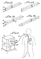
- the temperature-sensor wires 36 are initially separate wires, as shown in FIGURE 6A, which are brought together so that the insulating coatings 40 of the conductors 38 contact.
- the temperature-sensor wires 36 are then twisted together, as shown in FIGURE 6B.
- the temperature-sensor wires 36 may be bifilar which means that the insulating coatings 40 of the conductors 38 are attached along a seam 54.
- the bifilar temperature-sensor wires 36 are then twisted, resulting in the configuration shown in FIGURE 7B.
- the pitch of the temperature-sensor wires 36 shown in FIGURES 6B and 7B may vary according to the particular embodiment of the reduced-noise catheter 20. However, it is preferable for the pitch of the temperature-sensor wires 36 to be at least about two revolutions per centimeter (cm) (or about five revolutions per inch) and preferably within the range of about two revolutions per cm to about six revolutions per cm (or about 15 revolutions per inch).
- a coupling apparatus 56 may be connected to the proximal end 26 of the body portion 22.
- the coupling apparatus 56 includes a plurality of lumens (not shown) corresponding to and in communication with the lumens 28 of the body portion 22. From the lumens of the coupling apparatus 56 extends a plurality of coupling units 58.
- Each of the coupling units 58 a , 58 b , 58 c , ... 58 n includes a lead 60 and a couple 62 which are configured for the measurement of a specific cardiovascular function.
- any number of the couple units 58 may be used in the electrical measurement of various cardiac functions, in the introduction of fluids into the vascular system, or in conjunction with a balloon disposed at the distal end 24 of the body portion 22, and so on as known in the art.
- One of the coupling units 58 is used in conjunction with the heating element 30 (for example, coupling unit 58 b ), and another one of the coupling units is used in conjunction with the temperature sensor 32 (for example, coupling unit 58 c ).
- the heating-element wires 34 extend from lumen 28b of the body portion 22, through a corresponding lumen of the coupling apparatus 56, and through lead 60 b to couple 62 b of coupling unit 58 b .
- the temperature-sensor wires 36 extend from lumen 28 c of the body portion 22, through a corresponding lumen of the coupling apparatus 56, through lead 60 c to couple 62 c of coupling unit 58 c .
- FIGURE 8 A preferred implementation of the reduced-noise catheter 20 of the present invention is illustrated in FIGURE 8.
- the body portion 22 of the catheter 20 may be inserted into the cardiovascular system of a patient, which includes a heart 64 and blood vessels, by making an incision in the patient and inserting the body portion 22 into a blood vessel of the patient.
- the body portion 22 is urged intravascularly until the distal end 24 is positioned at a target location with the temperature sensor 32 downstream of the heating element 30.
- the target location is preferably within the pulmonary artery 66 so that the cardiac output of the right ventricle of the heart 64 may be measured.
- the body portion 22 of the catheter 20 may be inserted either jugularly, as indicated by A in FIGURE 8, or femorally, as indicated by B in FIGURE 8.
- Jugular access leads the catheter 20 through the superior vena cava and into the right atrium of the heart 64.
- Femoral access leads the catheter 20 into the inferior vena cava and into the right atrium of the heart 64.
- the distal end 24 may be urged into the right ventricle and through the pulmonary valve into the pulmonary artery 66.
- the couple 62 corresponding to the heating element 30 (i.e., couple 62b) is connected to a control unit 68 for providing electrical signals (for example, a cycle of pseudorandom binary sequences) to activate the heating element 30, and the couple 62 corresponding to the temperature sensor 32 (i.e., couple 62 c ) is connected to a processing unit 70 for processing electrical signals from the temperature sensor 32.
- the electrical signals from the temperature sensor 32 are used to calculate blood temperature which, in turn, is used to calculate cardiac output or blood flow.
- the heating element 30 is activated, heating the volume of blood passing over and around the heating element 30.
- the resistivity of the temperature sensor 32 changes from the heating of the blood, changing the signal received at the processing unit 70. Based upon known variables, cardiac output may be calculated. These calculations are known in the art and will not be detailed herein.
- the resistivity of the thermistor decreases as the temperature of the blood increases.
- the temperature-sensor wires 36 are twisted as described above.
- the bias signal is synchronous with the electrical signal (e.g. , a pulsed 100-kHz sine wave signal) applied to the heating element 30.
- the bias signal if not eliminated, creates a significant flow differential in the measurement of cardiac output.
- Flow differential is the difference in the measured flow of blood and the actual flow of blood.
- a bias signal decreases the integrity of the measurement. For example, if the actual flow of blood is 9 liters per minute (L/min) and the measured flow of blood is 10.3 L/min, then the flow differential is 1.3 L/min.
- preferred embodiments of the reduced-noise catheter 20 of the present invention yield flow differentials of less than 0.5 L/min, with a number of the preferred embodiments of the catheter 20 yielding flow differentials of less than 0.25 L/min.
- the reduced-noise catheter 20 may reduce the error in measuring blood flow by approximately 80%. Not only is this error reduction significant but it represents a critical and substantial advancement in the art of catheters.
- FIGURE 9 A plot of flow differentials of conventional catheters and of the reduced-noised catheter 20 of the present invention is illustrated in FIGURE 9.
- the inventors have determined that while the twisted temperature-sensor wires 36 significantly reduces noise of the signal reaching the processor 70, the twisted wires 36 have no direct effect on the DC voltage applied to the temperature sensor 32 or on the low voltage DC measurement of the temperature sensor 32 itself.
- the error is caused by either thermal interference or electromagnetic interference, or a combination of both. Both the thermal and the electromagnetic interference may be caused by the activation of the heating element 30.
- the electrical signal applied to the heating element 30 by the control unit 68 is relatively large (e.g., about 15 watts) when compared to the electrical signal received by the processing unit 70 from the temperature sensor 32 (e.g., on the order of millivolts).
- the errant DC bias voltage across the temperature sensor 32 is synchronous with the pulsing signal applied to the heating element 30. Accordingly, two time constants may be present: one resulting from thermal interference and one resulting from electromagnetic interference.
- the pitch of the temperature-sensor wires 36 preferably ranges from about two revolutions per cm to about six revolutions per cm.
- the temperature-sensor wires 36 may be twisted along substantially the overall length l BP of the body portion 22 (less the distance l 1 from the temperature sensor 32 to the distal end 24 of the body portion 22), the reduced-noise catheter 20 may be configured with the temperature-sensor wires 36 twisted only along that section of the body portion 22 at which the heating element 30 is located.
- the temperature-sensor wires 35 may be twisted along length l HE of the body portion 22, which length may be thought of as the zone of cross-talk.
- the temperature-sensor wires 36 may also be twisted along the length of the body portion 22 defined by the overall length l BP less the distance l 2 , i.e., the distance from the distal end of the heating element 30 to the distal end 24 of the body portion 22.
- This length of the body portion 22 represents the length along which the heating-element wires 34 and the temperature-sensor wires 36 are coexistent.
- the wires themselves may be relatively small (for example, less than about 0.25 mm (0.01 inch) in diameter) when compared to the heating-element wires 34. If the temperature sensor 32 includes a thermistor, the signal carried by the temperature-sensor wires 36 may be on the order of millivolts or smaller. Alternatively, if the temperature sensor 32 includes a current-based sensor, then the signal carried by the temperature-sensor wires 36 will be a small-magnitude current signal.
- the temperature-sensor wires 36 may be received in the same lumen 28 as that of the heating wires 34, which embodiment is shown in FIGURE 2B.
- the diameter ⁇ TW (See FIGURE 2A) of the lumen 28 in which the temperature-sensor wires 36 are to be received may be made smaller, thereby saving space in the body portion 22 or allowing the overall diameter ⁇ BP (see FIGURE 1) of the body portion 22 to be accordingly smaller.
- processing units which may be used to process the electrical signals from the temperature sensor 32 to calculate blood temperature, blood flow, cardiac output, etc.
- One type of processing unit for example, SupermoduleTM, which is available from Baxter Healthcare Corporation
- a voltage divider at the "front end” of the unit and applies a small voltage to the temperature sensor 32, which is schematically represented in FIGURE 10B.
- Another type of processing unit for example, Vigilance®, which is also available from Baxter Healthcare Corporation
- these two processing units 70a and 70b respond differently (i.e., oppositely) to the errant bias signal present on untwisted temperature-sensor wires 36. This different response is taken into consideration in configuring the preferred embodiment of the reduced-noise catheter 20 of the present invention.
- the temperature sensor 32 is a thermistor
- the resistance of the thermistor 32 decreases, as indicated by ⁇ R T .
- the voltage measured by the voltage divider increases, as indicated by ⁇ V V
- the voltage measured by the current divider decreases, as indicated by ⁇ V C .
- the errant bias offset signal E will be additive in the voltage divider (in FIGURE 10B) and will be subtractive in the current divider (in FIGURE 10C). Accordingly, any changes in temperature or in true resistance of the thermistor 32 will cause a proportional but opposite change in the measured values of the processing units 70 b and 70 c .
- the voltage-divider processing unit 70 b may measure 11 L/min
- the current-divider processing unit 70 c may measure 7 L/min.
- This inconsistency in processing units 70 is eliminated by the reduced-noise catheter 20 of the present invention because the errant bias signal E is substantially eliminated.
- an accurate and confident measurement of the cardiac output may be calculated.
- the overall length l BP of the body portion 22 may be any desired length suitable for measuring cardiac output in a patient, which is preferably about 110 cm, thereby allowing the body portion 22 of the catheter 20 to be inserted into the patient femorally.
- the distance 1, from the thermistor 32 to the distal end 24 of the body portion 22 may range up to about 10 cm but preferably ranges from about 3 cm to about 5 cm.
- the distance between the distal end of the heating element 32 (which may be activated either a DC signal or an AC signal) and the temperature sensor 30 (i.e., l 2 minus l 1 ) may range up to about 20 cm.
- the outer diameter ⁇ BP of the body portion 22 is preferably about 2.33 mm (7 French), although this diameter depends upon the number of lumens 28 of the body portion 22, the size of the lumens 28, and so on.
- the outer surface of the body portion 22 may have distance marks 72 evenly spaced along the length which indicate to a physician the distance the body portion 22 has been inserted into the vascular system of a patient.
- the reduced-noise catheter 20 preferably has about 5 to 7 lumens 28.
- the lumens 28, other than those used to house the heating-element and temperature-sensor wires 34 and 36, may be used for any purpose known in the art, for example, as an inflation lumen in conjunction with a balloon (not shown) disposed at the distal end 24 of the body portion 22.
- Catheter model Nos. 139, 746, and 757 available from the Edwards Critical Care of Irvine, California, which is a division of Baxter International Incorporated of Deerfield, Illinois, are examples of multi-lumen catheters which may be used for the reduced-noise catheter of the present invention.
- the catheter 20 may be configured with any suitable commercially available temperature sensor or thermistor.
Landscapes
- Health & Medical Sciences (AREA)
- Life Sciences & Earth Sciences (AREA)
- Physics & Mathematics (AREA)
- General Physics & Mathematics (AREA)
- Fluid Mechanics (AREA)
- Heart & Thoracic Surgery (AREA)
- Molecular Biology (AREA)
- Pathology (AREA)
- Engineering & Computer Science (AREA)
- Biomedical Technology (AREA)
- Physiology (AREA)
- Medical Informatics (AREA)
- Biophysics (AREA)
- Surgery (AREA)
- Animal Behavior & Ethology (AREA)
- General Health & Medical Sciences (AREA)
- Public Health (AREA)
- Veterinary Medicine (AREA)
- Cardiology (AREA)
- Hematology (AREA)
- Measuring Pulse, Heart Rate, Blood Pressure Or Blood Flow (AREA)
Description
Claims (15)
- A reduced-noise catheter (20) comprising:a) a body portion (22) having a distal end (24) and a proximal end (26);b) a plurality of lumens (28) formed in the body portion between the distal end and the proximal end;c) a heating element (30) disposed between the distal end and the proximal end of the body portion;d) a temperature sensor (32) disposed between the heating element and the distal end of the body portion;e) heating-element wires (34) connected to the heating element, extending from the heating element to the proximal end of the body portion in one of the lumens for communicating with a control unit, and for carrying an activation signal from the control unit to the heating element to activate the heating element; andf) temperature-sensor wires (36) connected to the temperature sensor, extending in one of the lumens for communicating with a processing unit, and for carrying a temperature-sensor signal from the temperature sensor to the processing unit for processing, characterized by said temperature-sensor wires extending in a twisted configuration from the temperature sensor to the proximal end of the body portion.
- The reduced-noise catheter of claim 1 wherein the temperature-sensor wires are twisted bifilar wires attached along a seam.
- The reduced-noise catheter of claim 1 or claim 2 wherein the temperature-sensor wires are separate wires twisted together.
- The reduced-noise catheter according to any of the preceding claims wherein the heating-element wires and the temperature-sensor wires extend to the proximal end in the same lumen.
- The reduced-noise catheter according to any of the preceding claims wherein the temperature-sensor wires have a pitch of at least two revolutions per cm.
- The reduced-noise catheter according to any of the preceding claims wherein the temperature sensor includes a thermistor.
- The reduced-noise catheter according to any of the preceding claims, wherein the temperature sensor has a portion exposed to the exterior of the body, the temperature sensor having a variable electrical resistance dependent on the temperature of the exposed portion.
- The reduced-noise catheter according to any of the preceding claims, wherein the catheter includes a current divider to determine the resistance of the temperature sensor.
- The reduced-noise catheter according to any of the preceding claims, wherein the catheter includes a voltage divider to determine the resistance of the temperature sensor.
- A method of reducing noise in a catheter, the catheter including a temperature sensor, a heating element, and a plurality of lumens, the noise being reduced in a signal from the temperature sensor, the method comprising the step of:twisting temperature-sensor wires connected to the temperature sensor at least along a portion of the catheter at which the heating element is disposed, the temperature-sensor wires being received within one of the lumens of the catheter.
- The method according to claim 10 wherein the temperature-sensor wires are twisted along the entire length of the lumen within which the temperature-sensor wires are received.
- The method according to claim 10 or claim 11 further comprising the step of:positioning the temperature-sensor wires in the same lumen within which heating-element wires connected to the heating element are received.
- The method according to any of claims 10 to 12 wherein the temperature sensor is located on a distal end of the catheter and has a variable resistance to temperature, the temperature sensor wires extending to a proximal end of the catheter, the heating element being disposed between the distal and proximal ends of the catheter and including electrically conductive portions exposed to the exterior of the catheter body and surrounding the temperature wires, and wherein the method further comprises transmitting a signal through the temperature sensor, reducing noise in the signal associated with the electromagnetic field of the heater element by twisting the temperature sensor wires in at least a portion surrounded by the heater element, and processing the reduced noise signal transmitted through the temperature sensor to determine the resistance of the temperature sensor.
- The method of claim 13, wherein the step of processing includes using a current divider to determine the resistance of the temperature sensor.
- The method of claim 13 or claim 14, wherein the step of processing includes using a voltage divider to determine the resistance of the temperature sensor.
Applications Claiming Priority (3)
| Application Number | Priority Date | Filing Date | Title |
|---|---|---|---|
| US72511796A | 1996-10-02 | 1996-10-02 | |
| US725117 | 1996-10-02 | ||
| PCT/US1997/017064 WO1998014114A1 (en) | 1996-10-02 | 1997-09-24 | Reduced-noise catheter |
Publications (2)
| Publication Number | Publication Date |
|---|---|
| EP0944351A1 EP0944351A1 (en) | 1999-09-29 |
| EP0944351B1 true EP0944351B1 (en) | 2005-03-23 |
Family
ID=24913227
Family Applications (1)
| Application Number | Title | Priority Date | Filing Date |
|---|---|---|---|
| EP97942675A Expired - Lifetime EP0944351B1 (en) | 1996-10-02 | 1997-09-24 | Reduced-noise catheter |
Country Status (4)
| Country | Link |
|---|---|
| EP (1) | EP0944351B1 (en) |
| AU (1) | AU4431897A (en) |
| DE (1) | DE69732854T2 (en) |
| WO (1) | WO1998014114A1 (en) |
Cited By (2)
| Publication number | Priority date | Publication date | Assignee | Title |
|---|---|---|---|---|
| US11779280B2 (en) | 2018-06-29 | 2023-10-10 | Biosense Webster (Israel) Ltd. | Reference wires to remove noise and artifacts in cardiac mapping catheter |
| US12186010B2 (en) | 2019-09-26 | 2025-01-07 | Biosense Webster (Israel) Ltd. | Wiring for multi-electrode catheter |
Families Citing this family (4)
| Publication number | Priority date | Publication date | Assignee | Title |
|---|---|---|---|---|
| US5971935A (en) * | 1998-05-01 | 1999-10-26 | Baxter International Inc. | Methods and apparatus for reducing noise in systems using thermistor catheters to measure biological functions |
| DE29907566U1 (en) * | 1999-04-28 | 1999-08-26 | Honsberg & Co. KG, 42897 Remscheid | Flow sensor |
| US20070167862A1 (en) * | 2005-11-29 | 2007-07-19 | Lopez George A | Cardiac output measurement devices and methods |
| ES2385603T3 (en) | 2007-11-23 | 2012-07-27 | Pulsion Medical Systems Ag | Central venous sensor assembly for measuring physiological data for the determination of cardiac output and procedure for determining cardiac output |
Family Cites Families (3)
| Publication number | Priority date | Publication date | Assignee | Title |
|---|---|---|---|---|
| US3359974A (en) * | 1963-10-07 | 1967-12-26 | Hassan H Khalil | Device for the thermal determination of cardiac volumetric performance |
| US4240441A (en) * | 1978-10-10 | 1980-12-23 | The United States Of America As Represented By The Secretary Of The Navy | Carotid thermodilution catheter |
| JP2866132B2 (en) * | 1990-01-29 | 1999-03-08 | テルモ株式会社 | Flow sensor probe |
-
1997
- 1997-09-24 AU AU44318/97A patent/AU4431897A/en not_active Abandoned
- 1997-09-24 WO PCT/US1997/017064 patent/WO1998014114A1/en not_active Ceased
- 1997-09-24 EP EP97942675A patent/EP0944351B1/en not_active Expired - Lifetime
- 1997-09-24 DE DE69732854T patent/DE69732854T2/en not_active Expired - Lifetime
Cited By (3)
| Publication number | Priority date | Publication date | Assignee | Title |
|---|---|---|---|---|
| US11779280B2 (en) | 2018-06-29 | 2023-10-10 | Biosense Webster (Israel) Ltd. | Reference wires to remove noise and artifacts in cardiac mapping catheter |
| US12551166B2 (en) | 2018-06-29 | 2026-02-17 | Biosense Webster (Israel) Ltd. | Reference wires to remove noise and artifacts in cardiac mapping catheter |
| US12186010B2 (en) | 2019-09-26 | 2025-01-07 | Biosense Webster (Israel) Ltd. | Wiring for multi-electrode catheter |
Also Published As
| Publication number | Publication date |
|---|---|
| DE69732854T2 (en) | 2005-08-11 |
| WO1998014114A1 (en) | 1998-04-09 |
| DE69732854D1 (en) | 2005-04-28 |
| EP0944351A1 (en) | 1999-09-29 |
| AU4431897A (en) | 1998-04-24 |
Similar Documents
| Publication | Publication Date | Title |
|---|---|---|
| US6355001B1 (en) | Thermodilution catheter method using a safe, flexible heating element | |
| US5588438A (en) | System and method for controlling the temperature of a catheter-mounted heater | |
| AU2011262989B2 (en) | Catheter for measuring electric potential | |
| US6926674B2 (en) | Combined pressure-volume sensor and guide wire assembly | |
| US3359974A (en) | Device for the thermal determination of cardiac volumetric performance | |
| EP1089667A1 (en) | Ep catheter | |
| GB2187100A (en) | Diagnostic catheter for monitoring cardiac output | |
| EP0417781B1 (en) | Cardiac output measuring catheter | |
| EP0944351A1 (en) | Reduced-noise catheter | |
| CA2129751C (en) | System and method for controlling the temperature of a catheter-mounted heater | |
| EP0303757A2 (en) | Dual-thermistor thermodilution catheter | |
| EP0637219B1 (en) | A thermodilution catheter having a safe, flexible heating element | |
| US20230310726A1 (en) | Advanced dialysis catheter with pressure sensor | |
| US5971935A (en) | Methods and apparatus for reducing noise in systems using thermistor catheters to measure biological functions | |
| JP4473375B2 (en) | Site coding device for medical device introduced into patient body | |
| US20070167864A1 (en) | Cardiac output measurement devices and methods | |
| CA2129551C (en) | A thermodilution catheter having a safe, flexible heating element | |
| CA2404534C (en) | System and method for controlling the temperature of a catheter-mounted heater |
Legal Events
| Date | Code | Title | Description |
|---|---|---|---|
| PUAI | Public reference made under article 153(3) epc to a published international application that has entered the european phase |
Free format text: ORIGINAL CODE: 0009012 |
|
| AK | Designated contracting states |
Kind code of ref document: A1 Designated state(s): BE DE ES FR GB NL |
|
| RAP1 | Party data changed (applicant data changed or rights of an application transferred) |
Owner name: EDWARDS LIFESCIENCES CORPORATION |
|
| 17P | Request for examination filed |
Effective date: 19990429 |
|
| GRAP | Despatch of communication of intention to grant a patent |
Free format text: ORIGINAL CODE: EPIDOSNIGR1 |
|
| GRAS | Grant fee paid |
Free format text: ORIGINAL CODE: EPIDOSNIGR3 |
|
| GRAA | (expected) grant |
Free format text: ORIGINAL CODE: 0009210 |
|
| AK | Designated contracting states |
Kind code of ref document: B1 Designated state(s): BE DE ES FR GB NL |
|
| PG25 | Lapsed in a contracting state [announced via postgrant information from national office to epo] |
Ref country code: NL Free format text: LAPSE BECAUSE OF FAILURE TO SUBMIT A TRANSLATION OF THE DESCRIPTION OR TO PAY THE FEE WITHIN THE PRESCRIBED TIME-LIMIT Effective date: 20050323 Ref country code: BE Free format text: LAPSE BECAUSE OF FAILURE TO SUBMIT A TRANSLATION OF THE DESCRIPTION OR TO PAY THE FEE WITHIN THE PRESCRIBED TIME-LIMIT Effective date: 20050323 |
|
| REG | Reference to a national code |
Ref country code: GB Ref legal event code: FG4D |
|
| REF | Corresponds to: |
Ref document number: 69732854 Country of ref document: DE Date of ref document: 20050428 Kind code of ref document: P |
|
| PG25 | Lapsed in a contracting state [announced via postgrant information from national office to epo] |
Ref country code: ES Free format text: LAPSE BECAUSE OF FAILURE TO SUBMIT A TRANSLATION OF THE DESCRIPTION OR TO PAY THE FEE WITHIN THE PRESCRIBED TIME-LIMIT Effective date: 20050704 |
|
| NLV1 | Nl: lapsed or annulled due to failure to fulfill the requirements of art. 29p and 29m of the patents act | ||
| PGFP | Annual fee paid to national office [announced via postgrant information from national office to epo] |
Ref country code: GB Payment date: 20050921 Year of fee payment: 9 |
|
| PLBE | No opposition filed within time limit |
Free format text: ORIGINAL CODE: 0009261 |
|
| STAA | Information on the status of an ep patent application or granted ep patent |
Free format text: STATUS: NO OPPOSITION FILED WITHIN TIME LIMIT |
|
| ET | Fr: translation filed | ||
| 26N | No opposition filed |
Effective date: 20051227 |
|
| GBPC | Gb: european patent ceased through non-payment of renewal fee |
Effective date: 20060924 |
|
| PG25 | Lapsed in a contracting state [announced via postgrant information from national office to epo] |
Ref country code: GB Free format text: LAPSE BECAUSE OF NON-PAYMENT OF DUE FEES Effective date: 20060924 |
|
| REG | Reference to a national code |
Ref country code: FR Ref legal event code: PLFP Year of fee payment: 20 |
|
| PGFP | Annual fee paid to national office [announced via postgrant information from national office to epo] |
Ref country code: DE Payment date: 20160823 Year of fee payment: 20 |
|
| PGFP | Annual fee paid to national office [announced via postgrant information from national office to epo] |
Ref country code: FR Payment date: 20160822 Year of fee payment: 20 |
|
| REG | Reference to a national code |
Ref country code: DE Ref legal event code: R071 Ref document number: 69732854 Country of ref document: DE |