EP0943816B1 - Hydraulic drive cylinder - Google Patents
Hydraulic drive cylinder Download PDFInfo
- Publication number
- EP0943816B1 EP0943816B1 EP99200845A EP99200845A EP0943816B1 EP 0943816 B1 EP0943816 B1 EP 0943816B1 EP 99200845 A EP99200845 A EP 99200845A EP 99200845 A EP99200845 A EP 99200845A EP 0943816 B1 EP0943816 B1 EP 0943816B1
- Authority
- EP
- European Patent Office
- Prior art keywords
- piston
- cylinder
- head
- piston rod
- side chamber
- Prior art date
- Legal status (The legal status is an assumption and is not a legal conclusion. Google has not performed a legal analysis and makes no representation as to the accuracy of the status listed.)
- Expired - Lifetime
Links
- 239000012530 fluid Substances 0.000 claims description 14
- 238000007789 sealing Methods 0.000 claims description 8
- 238000007599 discharging Methods 0.000 claims description 5
- 230000014759 maintenance of location Effects 0.000 description 2
- 230000000712 assembly Effects 0.000 description 1
- 238000000429 assembly Methods 0.000 description 1
- 230000000694 effects Effects 0.000 description 1
- 239000004744 fabric Substances 0.000 description 1
- 239000011521 glass Substances 0.000 description 1
- 239000002184 metal Substances 0.000 description 1
- 229920003023 plastic Polymers 0.000 description 1
Images



Classifications
-
- F—MECHANICAL ENGINEERING; LIGHTING; HEATING; WEAPONS; BLASTING
- F15—FLUID-PRESSURE ACTUATORS; HYDRAULICS OR PNEUMATICS IN GENERAL
- F15B—SYSTEMS ACTING BY MEANS OF FLUIDS IN GENERAL; FLUID-PRESSURE ACTUATORS, e.g. SERVOMOTORS; DETAILS OF FLUID-PRESSURE SYSTEMS, NOT OTHERWISE PROVIDED FOR
- F15B15/00—Fluid-actuated devices for displacing a member from one position to another; Gearing associated therewith
- F15B15/08—Characterised by the construction of the motor unit
- F15B15/14—Characterised by the construction of the motor unit of the straight-cylinder type
- F15B15/1409—Characterised by the construction of the motor unit of the straight-cylinder type with two or more independently movable working pistons
-
- B—PERFORMING OPERATIONS; TRANSPORTING
- B60—VEHICLES IN GENERAL
- B60J—WINDOWS, WINDSCREENS, NON-FIXED ROOFS, DOORS, OR SIMILAR DEVICES FOR VEHICLES; REMOVABLE EXTERNAL PROTECTIVE COVERINGS SPECIALLY ADAPTED FOR VEHICLES
- B60J7/00—Non-fixed roofs; Roofs with movable panels, e.g. rotary sunroofs
- B60J7/08—Non-fixed roofs; Roofs with movable panels, e.g. rotary sunroofs of non-sliding type, i.e. movable or removable roofs or panels, e.g. let-down tops or roofs capable of being easily detached or of assuming a collapsed or inoperative position
- B60J7/12—Non-fixed roofs; Roofs with movable panels, e.g. rotary sunroofs of non-sliding type, i.e. movable or removable roofs or panels, e.g. let-down tops or roofs capable of being easily detached or of assuming a collapsed or inoperative position foldable; Tensioning mechanisms therefor, e.g. struts
- B60J7/1226—Soft tops for convertible vehicles
- B60J7/1265—Soft tops for convertible vehicles characterised by kinematic movements, e.g. using parallelogram linkages
- B60J7/1269—Soft tops for convertible vehicles characterised by kinematic movements, e.g. using parallelogram linkages with remote power control
- B60J7/1273—Soft tops for convertible vehicles characterised by kinematic movements, e.g. using parallelogram linkages with remote power control using hydraulic means
Definitions
- the present invention relates to a hydraulic drive cylinder according to the preamble of claim 1.
- An hydraulic drive cylinder of this type is known from EP-A-0 309 066.
- the hydraulic cylinder has two connections for feeding and discharging hydraulic fluid, it being possible for the piston rod of the drive cylinder to be held hydraulically not only in the two end positions but also in an intermediate position.
- the invention relates in particular to a folding-roof assembly which is provided with a hydraulic drive cylinder of this nature.
- Double-acting hydraulic drive cylinders in which the piston rod is fixedly connected to the piston are generally known from the prior art.
- the piston rod of a drive cylinder of this nature has two end positions, namely the fully retracted position, in which the piston bears against the cylinder base, and the fully extended position, in which the piston bears against the cylinder head. If it is desired, in a cylinder of this nature, to hold the piston rod stationary in a predetermined intermediate position, a sensor is required in order to detect the position of the piston rod, and furthermore retention means are required in order to fix the piston rod in the intended intermediate position.
- Known retention means comprise, for example, a clamping device for the piston rod.
- Another known solution for fixing the piston rod in the intermediate position consists in providing a set of hydraulically actuable valves, e.g. pilot operated check valves, in the two hydraulic lines leading to the chambers of the cylinder, making it possible to prevent hydraulic fluid from flowing out of the chambers so that the piston rod is held hydraulically in place.
- a set of hydraulically actuable valves e.g. pilot operated check valves
- the prior art discloses so-called hydraulic tandem cylinders, in which two piston/piston-rod assemblies which lie in line with one another are present in the cylinder tube, each assembly comprising a piston and a piston rod which is fixedly connected thereto.
- the piston rod of one assembly in this case projects outwards.
- the two pistons form three variable chambers in the cylinder space, a separate connection for feeding and discharging hydraulic fluid being provided for each chamber.
- This design has the advantage over the example mentioned above that there is no need for a sensor and associated circuit for detecting the intermediate position of the piston rod.
- a drawback compared to a double-acting cylinder is that a tandem cylinder requires more, or more complex, hydraulic valves in order to control the feed and discharge of hydraulic fluid to and from the three chambers of the tandem cylinder.
- the object of the present invention is to provide a hydraulic drive cylinder with two connections, in which cylinder the piston rod can be held hydraulically not only in the end positions but also in an intermediate position which lies between the end positions.
- the present invention provides a hydraulic drive cylinder according to claim 1. Further advantageous embodiments of the drive cylinder, as well as a particularly advantageous use thereof for actuating the rear part of a folding roof of a convertible vehicle are described in the claims and the following description, with reference to the drawing.
- the hydraulic drive cylinder 1 shown in Figures 1-4 comprises a cylinder tube 2, which at its respective ends has a cylinder base 3 and a cylinder head 4, thus delimiting a cylinder space 5.
- the cylinder tube 2 may also have a different form from the metal cylindrical tube shown here.
- the cylinder base 3 could, for example, form a single unit with the cylinder tube 2.
- a piston 6 which can move to and fro between the cylinder base 3 and the cylinder head 4 and is provided with sealing means, in this case a sealing ring 24, which act in a sealing manner on the cylinder tube 2.
- sealing means in this case a sealing ring 24, which act in a sealing manner on the cylinder tube 2.
- the piston 6 delimits a head-side chamber 7, and on the side of the cylinder base 3, it delimits a base-side chamber 8. These chambers 7, 8 are sealed off from one another by the piston 6.
- a single connection 9, 10 for feeding and discharging hydraulic fluid is provided for each of the said chambers 7, 8.
- the drive cylinder 1 comprises a piston rod 12 which is coupled to the piston 6 and projects outwards through a bore in the cylinder head 4, a seal, in this case sealing rings 13, which acts on the piston rod, being arranged in the said bore.
- the piston rod 12 is provided at its end which projects outwards with a ball-and-socket joint 15, and the cylinder base 3 is provided with a bore 16 for receiving a second ball-and-socket joint.
- the piston rod 6 has a free end 20 which is delimited by an end face 21, which end face 21 is situated in the head-side chamber 7. At that free end 20, the piston rod 12 is provided with a first stop 22, which forms an annular stop face 23 which has a greater external diameter than the piston rod 12.
- the piston 6 is provided with a projection 25 which extends towards the cylinder head 4 inside the head-side chamber 7 and is provided, at a distance from the piston 6, with a second stop 26, in such a manner that the piston rod 12 can move to and fro along an axial travel with respect to the piston 6, between a retracted position with respect to the piston 6 and an extended position with respect to the piston 6.
- the projection or extension 25 is in this case designed as a semi-cylindrical wall with two limbs 28 at its end which is remote from the piston 6, which limbs form the second stop and between them form a slot through which the piston rod 12 projects.
- one projection 25 there may also be a plurality of projections, for example distributed around the circumference of the chamber 7, each with an associated second stop.
- the piston 6 is forced against the cylinder base 4 by the hydraulic pressure in the chamber 7.
- the hydraulic pressure in the chamber 7 ensures that the piston rod 12 is still being forced into its extended position with respect to the piston 6, with its stop 22 bearing against the stop 26 of the piston 6.
- connection 9 to the head-side chamber 7 is connected in such a manner that hydraulic fluid can flow out of the drive cylinder via the connection 9, it is possible, by exerting an external push-in force on the piston rod 12, to reach the fully retracted position shown in Figure 4.
- the piston rod 12 can move freely to and fro, within the travel length determined by the stops 22 and 26, with respect to the fully extended piston 6.
- the drive cylinder 1 according to the invention which has been explained with reference to Figures 1-4 can be used to good effect in a hydraulic actuating device for a folding roof of a convertible vehicle.
- An example of this application will be explained in more detail below with reference to Figures 5, 6 and 7.
- FIGS 5, 6 and 7 diagrammatically show part of a passenger vehicle 30 of the convertible type, having a body 32 and a passenger compartment 33 within.
- a passenger vehicle 30 of the convertible type having a body 32 and a passenger compartment 33 within.
- the side of the body in the section which lies behind the seats 34 of the vehicle is not shown here.
- the vehicle 30 comprises a folding roof 35 which, in the closed position, covers the passenger compartment 33 and, in the open position, is accommodated in a compartment 36 which lies behind the passenger compartment 32.
- a pivoting lid 37 is arranged at the rear edge of the compartment 36.
- the pivoting lid 37 can be pivoted, by means of drive means (not shown in more detail), for example a double-acting hydraulic cylinder, about an associated pivot pin 38 between a substantially horizontal position, in which the pivoting lid 37 closes off the compartment 36 and a vertical position in which the compartment 36 is open.
- a lid lock (not shown) is provided in order to lock the pivoting lid 37 in the position in which it closes off the compartment 36.
- the folding roof 35 comprises a foldable cover 39 made from a suitable fabric and a framework for the cover 39. Only those parts of the framework which are relevant for explaining the present invention are shown. These components comprise a substantially U-shaped main bracket 40, which at its two ends is arranged on the body 32 in such a manner that it can pivot about a substantially horizontal pivot pin 41, and furthermore a substantially U-shaped rear bracket 43, which extends along the rear edge of the cover 39 and is connected to the cover 39. At both its ends, the rear bracket 43 is arranged on the main bracket 40 in such a manner that it can pivot about a substantially horizontal pivot pin 44.
- a window 52 is arranged in that part of the cover 39 which lies between the rear bracket 43 and the main bracket 40.
- the window 52 is in this case rigid and cannot fold, being made, for example, of glass or a hard, transparent plastic.
- a hydraulic actuating device is provided for the purpose of moving the folding roof 35.
- this actuating device comprises a hydraulic unit (not shown) with an electrically driven pump, a hydraulic-fluid reservoir and hydraulic cylinders which are connected to the pump and the reservoir via associated lines.
- a pair of, or a single, double-acting hydraulic cylinder(s) (not shown) is/are used to pivot the main bracket 40.
- These cylinders may, for example, each be disposed between a support 56, which is attached to the body 32, and the main bracket 40.
- At least one cylinder 1 is provided, which in this example is disposed between the main bracket 40 and the rear bracket 43. If appropriate, two cylinders 1 are connected in parallel, a cylinder 1 acting on each side arm of the rear bracket 43.
- Figure 5 shows the closed position of the folding roof 35. In this closed position, the cylinder 1 is fully extended, cf. Figure 2, and the rear bracket 43 lies on top of the pivoting lid 37, which is in its horizontal, closed position.
- the cylinder 1 is in the intermediate position shown in Figure 3.
- the rear bracket 43 is not pivoted upwards to its maximum extent, but to a sufficient extent to open the pivoting lid 37. This is because opening the rear bracket 43 to its maximum extent in this position would, on the one hand, take longer and, on the other hand, damage the non-foldable window 52.
- the piston rod 12 is hydraulically fixed in place and, therefore, cannot be moved by applying an external force. Inter alia, this prevents the possibility of the rear bracket 43 in this intermediate position being moved manually, which may disrupt the sequence of movements.
- the cylinder 1 is extended again, possibly not completely, by feeding hydraulic fluid to both connections 9 and 10.
- the two connections 9 and 10 of the cylinder 1 are then connected to the reservoir of the pump unit, so that the piston rod 12 can move to and fro between its end positions virtually without any obstacles.
- the folding roof 35 is pivoted into the compartment 36.
- the rear bracket 43 is moved onto the base of the compartment 36, with the result that the piston rod 12 is retracted, virtually as far as the fully retracted position shown in Figure 4.
- the pivoting lid 37 can be closed, resulting in the position shown in Figure 7.
- the folding roof 35 is closed substantially in the reverse order, and this operation will not be described further here.
- drive cylinder 1 is also suitable for other applications, for example for pivoting the main bracket of the folding roof if an intermediate position is desirable in this operation.
Landscapes
- Engineering & Computer Science (AREA)
- Mechanical Engineering (AREA)
- Physics & Mathematics (AREA)
- Fluid Mechanics (AREA)
- General Engineering & Computer Science (AREA)
- Actuator (AREA)
- Vehicle Body Suspensions (AREA)
Abstract
Description
- The present invention relates to a hydraulic drive cylinder according to the preamble of
claim 1. An hydraulic drive cylinder of this type is known from EP-A-0 309 066. The hydraulic cylinder has two connections for feeding and discharging hydraulic fluid, it being possible for the piston rod of the drive cylinder to be held hydraulically not only in the two end positions but also in an intermediate position. The invention relates in particular to a folding-roof assembly which is provided with a hydraulic drive cylinder of this nature. - Double-acting hydraulic drive cylinders in which the piston rod is fixedly connected to the piston are generally known from the prior art. The piston rod of a drive cylinder of this nature has two end positions, namely the fully retracted position, in which the piston bears against the cylinder base, and the fully extended position, in which the piston bears against the cylinder head. If it is desired, in a cylinder of this nature, to hold the piston rod stationary in a predetermined intermediate position, a sensor is required in order to detect the position of the piston rod, and furthermore retention means are required in order to fix the piston rod in the intended intermediate position. Known retention means comprise, for example, a clamping device for the piston rod. Another known solution for fixing the piston rod in the intermediate position consists in providing a set of hydraulically actuable valves, e.g. pilot operated check valves, in the two hydraulic lines leading to the chambers of the cylinder, making it possible to prevent hydraulic fluid from flowing out of the chambers so that the piston rod is held hydraulically in place.
- Furthermore, the prior art discloses so-called hydraulic tandem cylinders, in which two piston/piston-rod assemblies which lie in line with one another are present in the cylinder tube, each assembly comprising a piston and a piston rod which is fixedly connected thereto. The piston rod of one assembly in this case projects outwards. The two pistons form three variable chambers in the cylinder space, a separate connection for feeding and discharging hydraulic fluid being provided for each chamber. In a cylinder of this nature, it is possible, by suitably pressurizing the three chambers, to provide an intermediate position for the piston rod which projects outwards, in which intermediate position the piston rod is held hydraulically in place by the pressure in the said chambers. This design has the advantage over the example mentioned above that there is no need for a sensor and associated circuit for detecting the intermediate position of the piston rod. However, a drawback compared to a double-acting cylinder is that a tandem cylinder requires more, or more complex, hydraulic valves in order to control the feed and discharge of hydraulic fluid to and from the three chambers of the tandem cylinder.
- The object of the present invention is to provide a hydraulic drive cylinder with two connections, in which cylinder the piston rod can be held hydraulically not only in the end positions but also in an intermediate position which lies between the end positions.
- The present invention provides a hydraulic drive cylinder according to
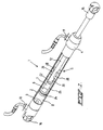
claim 1. Further advantageous embodiments of the drive cylinder, as well as a particularly advantageous use thereof for actuating the rear part of a folding roof of a convertible vehicle are described in the claims and the following description, with reference to the drawing. - Fig. 1 shows a perspective, partially cut-away view of a preferred embodiment of the hydraulic drive cylinder according to the invention,
- Fig. 2 shows the drive cylinder of Fig. 1 in the extended position,
- Fig. 3 shows the drive cylinder of Fig. 1 in an intermediate position,
- Fig. 4 shows the drive cylinder of Fig. 1 in the retracted position, and
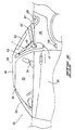
- Fig. 5 shows a diagrammatic side view of part of a vehicle of the convertible type with a folding-roof assembly in which the drive cylinder of Fig. 1 is used, with part of the body not shown and the folding roof in the closed position,
- Fig. 6 shows a view corresponding to Fig. 5, in which the drive cylinder is in the intermediate position, so that the rear part of the folding roof is pivoted upwards, and
- Fig. 7 shows a view in accordance with Fig. 5, with the folding roof in the open position.
-
- The
hydraulic drive cylinder 1 shown in Figures 1-4 comprises acylinder tube 2, which at its respective ends has acylinder base 3 and acylinder head 4, thus delimiting acylinder space 5. It will be clear that thecylinder tube 2 may also have a different form from the metal cylindrical tube shown here. Furthermore, thecylinder base 3 could, for example, form a single unit with thecylinder tube 2. - In the
cylinder space 5 there is apiston 6 which can move to and fro between thecylinder base 3 and thecylinder head 4 and is provided with sealing means, in this case asealing ring 24, which act in a sealing manner on thecylinder tube 2. On the side of thecylinder head 4, thepiston 6 delimits a head-side chamber 7, and on the side of thecylinder base 3, it delimits a base-side chamber 8. Thesechambers piston 6. - A
single connection said chambers - Furthermore, the
drive cylinder 1 comprises apiston rod 12 which is coupled to thepiston 6 and projects outwards through a bore in thecylinder head 4, a seal, in thiscase sealing rings 13, which acts on the piston rod, being arranged in the said bore. - In order to attach the
cylinder 1, thepiston rod 12 is provided at its end which projects outwards with a ball-and-socket joint 15, and thecylinder base 3 is provided with abore 16 for receiving a second ball-and-socket joint. - The
piston rod 6 has afree end 20 which is delimited by anend face 21, whichend face 21 is situated in the head-side chamber 7. At thatfree end 20, thepiston rod 12 is provided with afirst stop 22, which forms anannular stop face 23 which has a greater external diameter than thepiston rod 12. - Furthermore, the
piston 6 is provided with aprojection 25 which extends towards thecylinder head 4 inside the head-side chamber 7 and is provided, at a distance from thepiston 6, with asecond stop 26, in such a manner that thepiston rod 12 can move to and fro along an axial travel with respect to thepiston 6, between a retracted position with respect to thepiston 6 and an extended position with respect to thepiston 6. - In the extended position with respect to the
piston 6, thefirst stop 22 of thepiston rod 12 bears against thesecond stop 26 which is attached to thepiston 6 via theprojection 25. - It can clearly be seen from Figure 1 that the projection or
extension 25 is in this case designed as a semi-cylindrical wall with twolimbs 28 at its end which is remote from thepiston 6, which limbs form the second stop and between them form a slot through which the piston rod 12 projects. - The design shown ensures that when there is hydraulic pressure in the head-
side chamber 7 thepiston rod 12 adopts the extended position with respect to thepiston 6. - It will be clear that as an alternative to one
projection 25 there may also be a plurality of projections, for example distributed around the circumference of thechamber 7, each with an associated second stop. - The functioning of the
drive cylinder 1 which has been described with reference to Figure 1 will now be explained with reference to Figures 2, 3 and 4. - In Figure 2, the same hydraulic pressure is being applied at the
connection 10 and theconnection 9 of thedrive cylinder 1. Due to the difference in active surface area between thepiston 6 on the side of the base-side chamber 8, on the one hand, and on the side of the head-side chamber 7, on the other hand, thepiston 6 is forced towards its extended limit position. Since hydraulic pressure prevails in thechamber 7, thepiston rod 12 is held in its extended position with respect to thepiston 6, so that thepiston rod 12 is now in its fully extended position. - Allowing hydraulic fluid to flow out of the base-
side working chamber 8 via theconnection 10 while feeding hydraulic fluid in viaconnection 9 results in the intermediate position of thepiston rod 12 shown in Figure 3 being reached. In this position, thepiston 6 is forced against thecylinder base 4 by the hydraulic pressure in thechamber 7. The hydraulic pressure in thechamber 7 ensures that thepiston rod 12 is still being forced into its extended position with respect to thepiston 6, with itsstop 22 bearing against thestop 26 of thepiston 6. - If the
connection 9 to the head-side chamber 7 is connected in such a manner that hydraulic fluid can flow out of the drive cylinder via theconnection 9, it is possible, by exerting an external push-in force on thepiston rod 12, to reach the fully retracted position shown in Figure 4. - If hydraulic pressure is generated only in the base-
side chamber 8 and not in thechamber 7, thepiston rod 12 can move freely to and fro, within the travel length determined by thestops piston 6. - The
drive cylinder 1 according to the invention which has been explained with reference to Figures 1-4 can be used to good effect in a hydraulic actuating device for a folding roof of a convertible vehicle. An example of this application will be explained in more detail below with reference to Figures 5, 6 and 7. - Figures 5, 6 and 7 diagrammatically show part of a
passenger vehicle 30 of the convertible type, having abody 32 and apassenger compartment 33 within. For the sake of clarity, the side of the body in the section which lies behind theseats 34 of the vehicle is not shown here. - The
vehicle 30 comprises afolding roof 35 which, in the closed position, covers thepassenger compartment 33 and, in the open position, is accommodated in acompartment 36 which lies behind thepassenger compartment 32. To close off thecompartment 36, a pivotinglid 37 is arranged at the rear edge of thecompartment 36. The pivotinglid 37 can be pivoted, by means of drive means (not shown in more detail), for example a double-acting hydraulic cylinder, about an associatedpivot pin 38 between a substantially horizontal position, in which thepivoting lid 37 closes off thecompartment 36 and a vertical position in which thecompartment 36 is open. Furthermore, a lid lock (not shown) is provided in order to lock thepivoting lid 37 in the position in which it closes off thecompartment 36. - The folding
roof 35 comprises afoldable cover 39 made from a suitable fabric and a framework for thecover 39. Only those parts of the framework which are relevant for explaining the present invention are shown. These components comprise a substantially U-shapedmain bracket 40, which at its two ends is arranged on thebody 32 in such a manner that it can pivot about a substantiallyhorizontal pivot pin 41, and furthermore a substantially U-shapedrear bracket 43, which extends along the rear edge of thecover 39 and is connected to thecover 39. At both its ends, therear bracket 43 is arranged on themain bracket 40 in such a manner that it can pivot about a substantiallyhorizontal pivot pin 44. - A
window 52 is arranged in that part of thecover 39 which lies between therear bracket 43 and themain bracket 40. Thewindow 52 is in this case rigid and cannot fold, being made, for example, of glass or a hard, transparent plastic. - A hydraulic actuating device is provided for the purpose of moving the folding
roof 35. In this example, this actuating device comprises a hydraulic unit (not shown) with an electrically driven pump, a hydraulic-fluid reservoir and hydraulic cylinders which are connected to the pump and the reservoir via associated lines. A pair of, or a single, double-acting hydraulic cylinder(s) (not shown) is/are used to pivot themain bracket 40. These cylinders may, for example, each be disposed between asupport 56, which is attached to thebody 32, and themain bracket 40. - In order to pivot the
rear bracket 43, at least onecylinder 1 is provided, which in this example is disposed between themain bracket 40 and therear bracket 43. If appropriate, twocylinders 1 are connected in parallel, acylinder 1 acting on each side arm of therear bracket 43. - Figure 5 shows the closed position of the
folding roof 35. In this closed position, thecylinder 1 is fully extended, cf. Figure 2, and therear bracket 43 lies on top of the pivotinglid 37, which is in its horizontal, closed position. - To open the
folding roof 35, firstly the side windows are lowered, and the front edge of thefolding roof 35 is unlocked from thebar 61 above thewindscreen 62. Then, with the aid of thecylinder 1, therear bracket 43 is pivoted upwards into the position shown in Figure 6 by allowing hydraulic fluid to flow out viaconnection 10 and feeding hydraulic fluid in viaconnection 9. - In Figure 6, the
cylinder 1 is in the intermediate position shown in Figure 3. In this position, therear bracket 43 is not pivoted upwards to its maximum extent, but to a sufficient extent to open the pivotinglid 37. This is because opening therear bracket 43 to its maximum extent in this position would, on the one hand, take longer and, on the other hand, damage thenon-foldable window 52. In the intermediate position shown, thepiston rod 12 is hydraulically fixed in place and, therefore, cannot be moved by applying an external force. Inter alia, this prevents the possibility of therear bracket 43 in this intermediate position being moved manually, which may disrupt the sequence of movements. - After the pivoting
lid 37, which is pivoting upwards, has moved past, thecylinder 1 is extended again, possibly not completely, by feeding hydraulic fluid to bothconnections cylinder 1 is extended, the twoconnections cylinder 1 are then connected to the reservoir of the pump unit, so that thepiston rod 12 can move to and fro between its end positions virtually without any obstacles. Then, by suitably actuating the cylinders associated with themain bracket 40, thefolding roof 35 is pivoted into thecompartment 36. During this movement, therear bracket 43 is moved onto the base of thecompartment 36, with the result that thepiston rod 12 is retracted, virtually as far as the fully retracted position shown in Figure 4. Then, the pivotinglid 37 can be closed, resulting in the position shown in Figure 7. - The
folding roof 35 is closed substantially in the reverse order, and this operation will not be described further here. - It will be clear that the
drive cylinder 1 is also suitable for other applications, for example for pivoting the main bracket of the folding roof if an intermediate position is desirable in this operation.
Claims (5)
- Hydraulic drive cylinder (1) comprising a cylinder tube (2), which at its respective ends has a cylinder base (3) and a cylinder head (4), thus delimiting a cylinder space (5),characterized in that the piston rod (12) has a free end (20) which is delimited by an end face (21), which end face is situated in the head-side chamber (7), in that the piston rod (12) is provided, at said free end (20), with a first stop (22, 23), in that the piston (6) is provided with a projection (25) which extends towards the cylinder head (4) inside the head-side chamber (7) and is provided, at a distance from the piston (6), with a second stop (26, 28), in such a manner that the piston rod (12) can move to and fro along an axial travel with respect to the piston (6), between a retracted position with respect to the piston and an extended position with respect to the piston, in which the first and second stops bear against one another, and in such a manner that when hydraulic pressure is present in the head-side chamber (7) the piston rod (12) adopts the extended position with respect to the piston (6).a piston (6) which can move to and fro in the cylinder space (5) between the cylinder base and the cylinder head, is provided with sealing means (24) which act in a sealing manner on the cylinder tube (2) and delimits, on the side of the cylinder head, a head-side chamber (7) and, on the side of the cylinder base, a base-side chamber (8), which chambers (7, 8) are sealed off from one another by the piston (6),a single connection (9, 10) for feeding and discharging hydraulic fluid being provided for each of the said chambers (7, 8),a piston rod (12) which is coupled to the piston and projects outwards through a bore in the cylinder head (4), a seal (13), which acts on the piston rod, being arranged in the said bore,
- Drive cylinder according to claim 1, in which the projection (25) has a part which extends along the cylinder tube from the piston, which part, at a distance from the piston, bears the second stop (26).
- Drive cylinder according to claim 2, in which the second stop (26) has two limbs (28) with an opening between them, through which the piston rod (12) projects, which limbs form the second stop for the first stop of the piston rod.
- Drive cylinder according to claim 1, in which the first stop (22) forms an annular stop face (23) which has a greater external diameter than the piston rod.
- Folding-roof assembly for a vehicle which has a body (32) and a passenger compartment (33) within, the folding-roof assembly comprising a folding roof (35) which, in the closed position, covers the passenger compartment and, in the open position, does not cover the passenger compartment, the folding roof comprising a foldable cover (39) and a supporting framework for the cover, which framework has a main bracket (40) which is designed to be attached pivotably to the body, and furthermore has a pivotable rear bracket (43) which lies behind the main bracket and extends substantially along the rear edge of the cover of the folding roof, the folding-roof assembly furthermore comprising an actuating device for moving the folding roof, which actuating device comprises at least one hydraulic cylinder for pivoting the rear bracket, the hydraulic cylinder (1) comprising a cylinder tube (2), which at its respective ends has a cylinder base (3) and a cylinder head (4), thus delimiting a cylinder space (5),whereby the piston rod has a free end (20) which is delimited by an end face (21), which end face is situated in the head-side chamber (7), the piston rod being provided, at that free end, with a first stop (22), and whereby the piston is provided with a projection (25) which extends towards the cylinder head inside the head-side chamber and is provided, at a distance from the piston, with a second stop (26), in such a manner that the piston rod can move to and fro along an axial travel with respect to the piston, between a retracted position with respect to the piston and an extended position with respect to the piston, in which the first and second stops bear against one another, and in such a manner that when hydraulic pressure is present in the head-side chamber the piston rod adopts the extended position with respect to the piston.a piston (6) which can move to and fro in the cylinder space (5) between the cylinder base and the cylinder head, is provided with sealing means which act in a sealing manner on the cylinder tube (2) and delimits, on the side of the cylinder head, a head-side chamber (7) and, on the side of the cylinder base, a base-side chamber (8), which chambers (7, 8) are sealed off from one another by the piston (6),a single connection (9, 10) for feeding and discharging hydraulic fluid being provided for each of the said chambers (7, 8),a piston rod (12) which is coupled to the piston and projects outwards through a bore in the cylinder head, a seal (13), which acts on the piston rod, being arranged in the said bore,
Applications Claiming Priority (2)
| Application Number | Priority Date | Filing Date | Title |
|---|---|---|---|
| NL1008656A NL1008656C2 (en) | 1998-03-20 | 1998-03-20 | Hydraulic drive cylinder. |
| NL1008656 | 1998-03-20 |
Publications (2)
| Publication Number | Publication Date |
|---|---|
| EP0943816A1 EP0943816A1 (en) | 1999-09-22 |
| EP0943816B1 true EP0943816B1 (en) | 2003-11-05 |
Family
ID=19766780
Family Applications (1)
| Application Number | Title | Priority Date | Filing Date |
|---|---|---|---|
| EP99200845A Expired - Lifetime EP0943816B1 (en) | 1998-03-20 | 1999-03-18 | Hydraulic drive cylinder |
Country Status (5)
| Country | Link |
|---|---|
| US (1) | US6152709A (en) |
| EP (1) | EP0943816B1 (en) |
| AT (1) | ATE253691T1 (en) |
| DE (1) | DE69912503T2 (en) |
| NL (1) | NL1008656C2 (en) |
Families Citing this family (2)
| Publication number | Priority date | Publication date | Assignee | Title |
|---|---|---|---|---|
| US20030024382A1 (en) * | 2001-07-25 | 2003-02-06 | Gram Martin M. | Lock-up device |
| CN106438557A (en) * | 2016-10-10 | 2017-02-22 | 合肥协力液压科技有限公司 | Hydraulic cylinder |
Family Cites Families (9)
| Publication number | Priority date | Publication date | Assignee | Title |
|---|---|---|---|---|
| US762627A (en) * | 1904-01-21 | 1904-06-14 | Ferdinand Fink | Fluid-pressure motor. |
| US2893353A (en) * | 1954-08-13 | 1959-07-07 | Gen Motors Corp | Three position actuator cylinder |
| US3008454A (en) * | 1959-04-03 | 1961-11-14 | Ralph M Wilkins | Locking actuator |
| US3269275A (en) * | 1964-07-21 | 1966-08-30 | Soil Mover Company Inc | Two stage hydraulic cylinder |
| US3614912A (en) * | 1969-09-29 | 1971-10-26 | Lionel Pacific Inc | Telescoping piston central lock hydraulic actuator |
| US4199007A (en) * | 1978-02-27 | 1980-04-22 | E-Systems, Inc. | High frequency-high flow servo valve |
| NL8702269A (en) * | 1987-09-23 | 1989-04-17 | Applied Power Inc | PRESSURE MEDIUM PISTON CYLINDER DEVICE. |
| JP2762089B2 (en) * | 1989-01-13 | 1998-06-04 | 曙ブレーキ工業株式会社 | Three-position positioning hydraulic cylinder |
| DE4438925C1 (en) * | 1994-10-31 | 1995-11-09 | Porsche Ag | Folding roof for motor vehicle |
-
1998
- 1998-03-20 NL NL1008656A patent/NL1008656C2/en not_active IP Right Cessation
-
1999
- 1999-03-17 US US09/271,006 patent/US6152709A/en not_active Expired - Lifetime
- 1999-03-18 DE DE69912503T patent/DE69912503T2/en not_active Expired - Lifetime
- 1999-03-18 AT AT99200845T patent/ATE253691T1/en not_active IP Right Cessation
- 1999-03-18 EP EP99200845A patent/EP0943816B1/en not_active Expired - Lifetime
Also Published As
| Publication number | Publication date |
|---|---|
| US6152709A (en) | 2000-11-28 |
| EP0943816A1 (en) | 1999-09-22 |
| DE69912503T2 (en) | 2004-09-23 |
| DE69912503D1 (en) | 2003-12-11 |
| ATE253691T1 (en) | 2003-11-15 |
| NL1008656C2 (en) | 1999-09-21 |
Similar Documents
| Publication | Publication Date | Title |
|---|---|---|
| US5145313A (en) | Quick disconnect bucket actuator | |
| ITRM960260A1 (en) | DRIVE COMPLEX FOR A LOCKABLE PART OF A VEHICLE. | |
| US6325445B1 (en) | Motor vehicle with a body | |
| US6386598B1 (en) | Locking power clamp | |
| US6416111B1 (en) | Cross folding convertible top | |
| US2267471A (en) | Collapsible top for motor vehicles | |
| US20020014780A1 (en) | Rebalancing circuit for a truck cover sliding pivot | |
| CA1080085A (en) | Cylinder construction affording automatic re-phasing of master and slave cylinders | |
| EP0309066B1 (en) | Piston-cylinder device to be powered by a pressure fluid | |
| US20030057725A1 (en) | Vehicle structure | |
| US5865497A (en) | Pneumatic strut for a motor vechicle | |
| US6152709A (en) | Hydraulic drive cylinder | |
| US3640608A (en) | Automatically controlled mirror | |
| US6106343A (en) | Shock absorbing arrangement for marine outboard drive | |
| US7100962B2 (en) | Convertible roof bow control mechanism | |
| US7055637B2 (en) | Hydraulic tilting device for tilting a vehicle cab, and vehicle provided with tilting device of this type | |
| US3661215A (en) | Tilting dozer blade | |
| EP0932541B1 (en) | Hydraulic tilting device for a cab | |
| US6536830B1 (en) | Convertible top for a motor vehicle and the like | |
| US3536382A (en) | Automatically controlled mirror | |
| EP1527991A2 (en) | Marine steering system having swivel bracket forming hydraulic cylinder | |
| US7543656B2 (en) | Breathing for single acting hydraulic cylinders | |
| GB2149281A (en) | Improvements in or relating to crop spraying equipment | |
| US5954315A (en) | Hydraulic spring compressor | |
| NL1008475C2 (en) | Double-acting hydraulic drive cylinder, especially for tilting a cabin of a vehicle. |
Legal Events
| Date | Code | Title | Description |
|---|---|---|---|
| PUAI | Public reference made under article 153(3) epc to a published international application that has entered the european phase |
Free format text: ORIGINAL CODE: 0009012 |
|
| AK | Designated contracting states |
Kind code of ref document: A1 Designated state(s): AT DE FR GB NL |
|
| AX | Request for extension of the european patent |
Free format text: AL;LT;LV;MK;RO;SI |
|
| 17P | Request for examination filed |
Effective date: 19991012 |
|
| AKX | Designation fees paid |
Free format text: AT DE FR GB NL |
|
| RAP1 | Party data changed (applicant data changed or rights of an application transferred) |
Owner name: ACTUANT CORPORATION |
|
| GRAH | Despatch of communication of intention to grant a patent |
Free format text: ORIGINAL CODE: EPIDOS IGRA |
|
| GRAS | Grant fee paid |
Free format text: ORIGINAL CODE: EPIDOSNIGR3 |
|
| GRAA | (expected) grant |
Free format text: ORIGINAL CODE: 0009210 |
|
| AK | Designated contracting states |
Kind code of ref document: B1 Designated state(s): AT DE FR GB NL |
|
| PG25 | Lapsed in a contracting state [announced via postgrant information from national office to epo] |
Ref country code: AT Free format text: LAPSE BECAUSE OF FAILURE TO SUBMIT A TRANSLATION OF THE DESCRIPTION OR TO PAY THE FEE WITHIN THE PRESCRIBED TIME-LIMIT Effective date: 20031105 |
|
| REG | Reference to a national code |
Ref country code: GB Ref legal event code: FG4D |
|
| REF | Corresponds to: |
Ref document number: 69912503 Country of ref document: DE Date of ref document: 20031211 Kind code of ref document: P |
|
| PG25 | Lapsed in a contracting state [announced via postgrant information from national office to epo] |
Ref country code: GB Free format text: LAPSE BECAUSE OF NON-PAYMENT OF DUE FEES Effective date: 20040318 |
|
| ET | Fr: translation filed | ||
| PLBE | No opposition filed within time limit |
Free format text: ORIGINAL CODE: 0009261 |
|
| STAA | Information on the status of an ep patent application or granted ep patent |
Free format text: STATUS: NO OPPOSITION FILED WITHIN TIME LIMIT |
|
| 26N | No opposition filed |
Effective date: 20040806 |
|
| GBPC | Gb: european patent ceased through non-payment of renewal fee |
Effective date: 20040318 |
|
| PGFP | Annual fee paid to national office [announced via postgrant information from national office to epo] |
Ref country code: NL Payment date: 20050330 Year of fee payment: 7 |
|
| PG25 | Lapsed in a contracting state [announced via postgrant information from national office to epo] |
Ref country code: NL Free format text: LAPSE BECAUSE OF NON-PAYMENT OF DUE FEES Effective date: 20061001 |
|
| NLV4 | Nl: lapsed or anulled due to non-payment of the annual fee |
Effective date: 20061001 |
|
| PGFP | Annual fee paid to national office [announced via postgrant information from national office to epo] |
Ref country code: DE Payment date: 20120327 Year of fee payment: 14 |
|
| PGFP | Annual fee paid to national office [announced via postgrant information from national office to epo] |
Ref country code: FR Payment date: 20120417 Year of fee payment: 14 |
|
| REG | Reference to a national code |
Ref country code: FR Ref legal event code: ST Effective date: 20131129 |
|
| REG | Reference to a national code |
Ref country code: DE Ref legal event code: R119 Ref document number: 69912503 Country of ref document: DE Effective date: 20131001 |
|
| PG25 | Lapsed in a contracting state [announced via postgrant information from national office to epo] |
Ref country code: DE Free format text: LAPSE BECAUSE OF NON-PAYMENT OF DUE FEES Effective date: 20131001 Ref country code: FR Free format text: LAPSE BECAUSE OF NON-PAYMENT OF DUE FEES Effective date: 20130402 |