EP0942425B1 - Tape drive head cleaner - Google Patents
Tape drive head cleaner Download PDFInfo
- Publication number
- EP0942425B1 EP0942425B1 EP19990301894 EP99301894A EP0942425B1 EP 0942425 B1 EP0942425 B1 EP 0942425B1 EP 19990301894 EP19990301894 EP 19990301894 EP 99301894 A EP99301894 A EP 99301894A EP 0942425 B1 EP0942425 B1 EP 0942425B1
- Authority
- EP
- European Patent Office
- Prior art keywords
- head
- cleaning
- pad
- fibers
- tape
- Prior art date
- Legal status (The legal status is an assumption and is not a legal conclusion. Google has not performed a legal analysis and makes no representation as to the accuracy of the status listed.)
- Expired - Lifetime
Links
Images


Classifications
-
- G—PHYSICS
- G11—INFORMATION STORAGE
- G11B—INFORMATION STORAGE BASED ON RELATIVE MOVEMENT BETWEEN RECORD CARRIER AND TRANSDUCER
- G11B25/00—Apparatus characterised by the shape of record carrier employed but not specific to the method of recording or reproducing, e.g. dictating apparatus; Combinations of such apparatus
- G11B25/06—Apparatus characterised by the shape of record carrier employed but not specific to the method of recording or reproducing, e.g. dictating apparatus; Combinations of such apparatus using web-form record carriers, e.g. tape
- G11B25/063—Apparatus characterised by the shape of record carrier employed but not specific to the method of recording or reproducing, e.g. dictating apparatus; Combinations of such apparatus using web-form record carriers, e.g. tape using tape inside container
-
- G—PHYSICS
- G11—INFORMATION STORAGE
- G11B—INFORMATION STORAGE BASED ON RELATIVE MOVEMENT BETWEEN RECORD CARRIER AND TRANSDUCER
- G11B15/00—Driving, starting or stopping record carriers of filamentary or web form; Driving both such record carriers and heads; Guiding such record carriers or containers therefor; Control thereof; Control of operating function
- G11B15/60—Guiding record carrier
- G11B15/66—Threading; Loading; Automatic self-loading
- G11B15/67—Threading; Loading; Automatic self-loading by extracting end of record carrier from container or spool
-
- G—PHYSICS
- G11—INFORMATION STORAGE
- G11B—INFORMATION STORAGE BASED ON RELATIVE MOVEMENT BETWEEN RECORD CARRIER AND TRANSDUCER
- G11B21/00—Head arrangements not specific to the method of recording or reproducing
-
- G—PHYSICS
- G11—INFORMATION STORAGE
- G11B—INFORMATION STORAGE BASED ON RELATIVE MOVEMENT BETWEEN RECORD CARRIER AND TRANSDUCER
- G11B5/00—Recording by magnetisation or demagnetisation of a record carrier; Reproducing by magnetic means; Record carriers therefor
- G11B5/41—Cleaning of heads
-
- G—PHYSICS
- G11—INFORMATION STORAGE
- G11B—INFORMATION STORAGE BASED ON RELATIVE MOVEMENT BETWEEN RECORD CARRIER AND TRANSDUCER
- G11B5/00—Recording by magnetisation or demagnetisation of a record carrier; Reproducing by magnetic means; Record carriers therefor
- G11B5/10—Structure or manufacture of housings or shields for heads
- G11B5/11—Shielding of head against electric or magnetic fields
Definitions
- the invention relates generally to tape drives and, more particularly, to a tape drive head cleaner that uses a cleaning pad mounted in the tape drive.
- Information is recorded on and read from a moving magnetic tape with a magnetic read/write head positioned next to the tape.
- the magnetic "head" may be a single head or, as is common, a series of read/write head elements arranged individually and/or in pairs within the head unit. Data is recorded in tracks on the tape by moving the tape lengthwise past the head.
- the head elements are selectively activated by electric currents representing the information to be recorded on the tape.
- the information is read from the tape by moving the tape longitudinally past the head elements so that magnetic flux patterns on the tape create electric signals in the head elements. These signals represent the information stored on the tape.
- the head cleaning device is built into some tape drives.
- the IBM Magstar 3590 TM tape drive for example, includes a cleaning brush that contacts the head during the tape threading operation. As the leader block on the tape is pulled into the tape cartridge, the leader block hits a lever that brings the cleaning brush into contact with the head. An actuator moves the head up and down to provide a scrubbing action between the head and the brush.
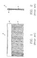
- a prior art brush such as the brush used in the IBM Magstar 3590, is shown in the front and side elevation views of Figs. 1 and 2. These brushes 2 are quite narrow since the bristles 4 are crimped into a holder 6. If a wider brush is desired, multiple brushes are placed side by side. This configuration adds to the cost and complexity of the cleaning device. Also, since the holder must grasp the bristles, it is not possible to make a brush that is very short, about 2-3 mm, along the length of the bristles. Hence, some tape drive designs may not have enough room to accommodate this type of cleaning brush. Further, it is difficult to hold the bristles securely in place using crimped holder brushes. Any stray bristles that are dislodged from the holder during brushing operations could seriously effect the performance of the tape drive, or even cause the drive to fail.
- EP-A-0800162 which is considered to present the closest date of the art, discloses an oscillating magnetic head and stationary brush cleaning apparatus.
- the cleaning apparatus cleans the air bearing surface of a magnetic head of a tape drive by employing components of an actuator for oscillating the magnetic head against bristles of a brush assembly.
- the brush is formed by crimping the bristles into slots in the brush assembly.
- EP-A-0530837 discloses a similar brush for cleaning magnetic heads to that disclosed in EP 0800162.
- US-A-5,710,684 discloses a cleaning mechanism for a magnetic head and a method of producing a cleaning brush having brush pieces integrally moulded with a resin block.
- GB 352330 discloses improvements in or relating to body brushes in which bristles are caused to project through perforations in a sheet, of rubber for example, and are held by the fixation of another sheet to the back of the first sheet.
- GB 1084766 discloses improvements in or relating to the manufacture of bristle-surface products in which loops of bristle material are formed on a flexible backing, either with or without a locking filament on the rear of the backing. The loops can be cut to form single bristles.
- the present invention is directed to a head cleaning device as claimed hereinafter that utilizes a cleaning pad to help overcome some of the disadvantages of conventional head cleaners.
- a tape drive as claimed hereinafter, is also provided.
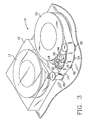
- Figs. 3 and 4 illustrate the internal operating configuration of a tape drive 10 with a tape cartridge 12 loaded in tape drive 10.
- Tape 14 moves over a magnetic tape head 16.
- Head 16 typically contains a number of read/write head elements that read data from or write data to tape 14.
- Actuator 24 moves head 16 up and down to properly position the read/write elements relative to tape 14.
- a head cleaning mechanism, designated generally by reference number 18, includes an arm 20 and cleaning pad 22. Cleaning pad 22 is secured to the end 21 of arm 20.
- Arm 20, which serves as a carrier for pad 22, is mounted to a second actuator 26.
- Tape 14 moves between a supply spool 11 in cartridge 12 and a take-up spool 13 in tape drive 10. Tape 14 travels around guide rollers 28 and 30 and optional stationary guides 32 and 34.
- arm 20 pivots out at the urging of arm actuator 26 so that cleaning pad 22 contacts head 18 as shown by the dotted lines in Fig. 4.
- Arm 20 and arm actuator 26 illustrate one mechanism for moving cleaning pad 22 into contact with head 16. Other mechanisms may be used.
- the particular mechanism used to move cleaning pad 22 into contact with head 16 is not important to the present invention except to the extent the mechanism carries cleaning pad 22 into contact with head 16.
- the details of the structure and operation of tape drive 10 are described in more detail in application Serial No. 09/042,323, entitled Head Cleaner For Linear Tape Drive and filed March 13, 1998.
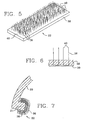
- cleaning pad 22 includes cleaning fibers 36 integrated into a backing 38.
- cleaning fibers 36 may vary between a dense array of thin flexible filaments to a more open array of coarse stiff bristles.
- arm actuator 26 is configured to move cleaning pad 22 and, correspondingly, fibers 36 back and forth across head 16.
- head actuator 24, which is typically configured to move head 16 up and down, will add a vertical cleaning motion by moving head 16 up and down across cleaning pad 22.
- Fibers 36 should be formed or trimmed to the desired length leaving the ends 40 of the fibers 36 exposed for contacting head 16 during cleaning. It is desirable to leave the fiber ends exposed to reach into the small contours of a variety of different heads and head elements. If the fiber ends are looped to return to the backing, the fibers will not be as effective to reach into the small contours of the head.
- Fibers 36 may be integrated into backing 38 using any suitable method.
- fibers 36 may be sewn or woven into backing 38 and, preferably, further secured to the backing with an adhesive 39 (shown in Fig. 6).
- adhesive 39 shown in Fig. 6
- Backing 38 and/or adhesive 39 should also be made from a statically dissipative or conductive material so that the entire cleaning pad 22 may be easily grounded to further reduce static charge build up.
- the cleaning pad of the present invention allows the length of cleaning pad 22 in the fiber direction to be shorter than conventional crimped cleaning brushes. This feature allows the use of cleaning pad 22 in tape drives that otherwise would not accommodate a cleaning mechanism.
- Cleaning pad 22 may be manufactured to any desired size and shape. Hence, there is no need to secure multiple pads together to construct "wide” cleaners as with conventional brush designs.
- cleaning pad 22 A variety of techniques could be used to manufacture cleaning pad 22. For example, a large piece of backing in which the cleaning fibers have been woven could be stamped into the desired pattern(s) for cleaning pads 22. To eliminate loose fibers at the edges of the cuts, which might be dislodged during cleaning operations, the fibers could be woven into the backing in the desired pattern leaving a cutting space between adjacent cleaning pad patterns. Individual cleaning pads 22, shown in Fig. 5, can then be cut through the cutting spaces to produce a border area 42 around each cleaning pad 22 so that there are no loose fibers at the cut edges. Alternative techniques to minimize the risk of dislodging loose edge fibers are illustrated in Figs. 7-9. In Fig. 7, cleaning pad 22 is wrapped around the end 21 of arm 20.
- cleaning pad 22 in this fashion moves the cut ends/edges away from the area of the pad that contacts head 16.
- cleaning pad 22 is mounted to a form 44. Fibers 36 of cleaning pad 22 are woven to the desired width so that there are no loose fibers along the lengthwise edge 46.
- the ends 48 of form 44 are crimped (for a metal form 44) over cut ends 50 to contain loose fibers. If form 44 is molded from plastic, pockets 52 are formed to contain any loose fibers at the cut ends 50.
- Pad 22 may be secured to plastic form 44 by, for example, gluing the pad to the form and/or heat crimping pockets 52 on to the pad.
- a bead of adhesive material 54 is placed along cut ends 50 to contain loose fibers.
- Form 44 may be curved if necessary or desirable to keep the crimped ends 48 or bead of adhesive material 54 from contacting the head of the tape drive during cleaning operations.
- Form 44 may be constructed as a discrete component secured to arm/carrier 20. Alternatively, form 44 maybe formed integral to arm 20.
- the cleaning pad of the present invention is not limited to use with a magnetic head in the linear tape drive described and shown above.
- the cleaning pad might also be used in connection with any of a variety of storage devices that use magnetic or other types of transducer heads, including both linear and helical scan tape drives.
- the invention therefore, is to be construed broadly within the scope of the following claims.
Landscapes
- Cleaning In General (AREA)
- Treatment Of Fiber Materials (AREA)
- Cleaning Implements For Floors, Carpets, Furniture, Walls, And The Like (AREA)
Description
- The invention relates generally to tape drives and, more particularly, to a tape drive head cleaner that uses a cleaning pad mounted in the tape drive.
- Information is recorded on and read from a moving magnetic tape with a magnetic read/write head positioned next to the tape. The magnetic "head" may be a single head or, as is common, a series of read/write head elements arranged individually and/or in pairs within the head unit. Data is recorded in tracks on the tape by moving the tape lengthwise past the head. The head elements are selectively activated by electric currents representing the information to be recorded on the tape. The information is read from the tape by moving the tape longitudinally past the head elements so that magnetic flux patterns on the tape create electric signals in the head elements. These signals represent the information stored on the tape.
- The performance of the head may be adversely effected by debris that often accumulates on the head. Consequently, the head should be cleaned periodically to remove debris. Several different techniques and devices have been used to clean the head. Cleaning tape cartridges use abrasive tape to clean the head. U.S. Patent No. 5,671,108 describes an open cell foam cleaning pad used in a cleaning cartridge instead of a cleaning tape.
- The head cleaning device is built into some tape drives. The IBM Magstar 3590™ tape drive, for example, includes a cleaning brush that contacts the head during the tape threading operation. As the leader block on the tape is pulled into the tape cartridge, the leader block hits a lever that brings the cleaning brush into contact with the head. An actuator moves the head up and down to provide a scrubbing action between the head and the brush.
- A prior art brush, such as the brush used in the IBM Magstar 3590, is shown in the front and side elevation views of Figs. 1 and 2. These
brushes 2 are quite narrow since thebristles 4 are crimped into aholder 6. If a wider brush is desired, multiple brushes are placed side by side. This configuration adds to the cost and complexity of the cleaning device. Also, since the holder must grasp the bristles, it is not possible to make a brush that is very short, about 2-3 mm, along the length of the bristles. Hence, some tape drive designs may not have enough room to accommodate this type of cleaning brush. Further, it is difficult to hold the bristles securely in place using crimped holder brushes. Any stray bristles that are dislodged from the holder during brushing operations could seriously effect the performance of the tape drive, or even cause the drive to fail. - EP-A-0800162, which is considered to present the closest date of the art, discloses an oscillating magnetic head and stationary brush cleaning apparatus. The cleaning apparatus cleans the air bearing surface of a magnetic head of a tape drive by employing components of an actuator for oscillating the magnetic head against bristles of a brush assembly. The brush is formed by crimping the bristles into slots in the brush assembly.
- EP-A-0530837 discloses a similar brush for cleaning magnetic heads to that disclosed in EP 0800162.
- US-A-5,710,684 discloses a cleaning mechanism for a magnetic head and a method of producing a cleaning brush having brush pieces integrally moulded with a resin block.
- GB 352330 discloses improvements in or relating to body brushes in which bristles are caused to project through perforations in a sheet, of rubber for example, and are held by the fixation of another sheet to the back of the first sheet.
- GB 1084766 discloses improvements in or relating to the manufacture of bristle-surface products in which loops of bristle material are formed on a flexible backing, either with or without a locking filament on the rear of the backing. The loops can be cut to form single bristles.
- Accordingly, the present invention is directed to a head cleaning device as claimed hereinafter that utilizes a cleaning pad to help overcome some of the disadvantages of conventional head cleaners. A tape drive, as claimed hereinafter, is also provided.
-
- Fig. 1 is a front elevation view of a prior art cleaning brush.
- Fig. 2 is a side elevation view of the prior art cleaning brush of Fig. 1.
- Fig. 3 is a simplified partial perspective view of the inside of a tape drive showing one type of cleaning mechanism that incorporates the cleaning pad of the present invention.
- Fig. 4 is a plan view of the tape drive of Fig. 3.
- Fig. 5 is a detail perspective view of one embodiment of the cleaning pad shown in the tape drive of Fig. 3.
- Fig. 6 is a partial cross section view of the cleaning pad of Fig. 4 showing one configuration for integrating the bristle fibers into the backing material.
- Fig. 7 is a cross section view of the cleaning pad attached to the end of the arm of the cleaning mechanism of Fig. 3 in which the pad extends around the sides of the arm to move any loose fibers at the edges of the cleaning pad away from contact with the head.
- Fig. 8 is a perspective view of the cleaning pad mounted to a form having ends crimped over the cut ends of the pad to contain any loose fibers.
- Fig. 9 is a perspective view of the cleaning pad mounted to a form having a bead of adhesive placed along the cut ends of the pad to contain any loose fibers.
- Figs. 3 and 4 illustrate the internal operating configuration of a
tape drive 10 with atape cartridge 12 loaded intape drive 10.Tape 14 moves over amagnetic tape head 16.Head 16 typically contains a number of read/write head elements that read data from or write data to tape 14.Actuator 24 moveshead 16 up and down to properly position the read/write elements relative totape 14. A head cleaning mechanism, designated generally byreference number 18, includes anarm 20 andcleaning pad 22.Cleaning pad 22 is secured to theend 21 ofarm 20.Arm 20, which serves as a carrier forpad 22, is mounted to asecond actuator 26. -
Tape 14 moves between asupply spool 11 incartridge 12 and a take-up spool 13 intape drive 10.Tape 14 travels aroundguide rollers stationary guides arm actuator 26 so thatcleaning pad 22contacts head 18 as shown by the dotted lines in Fig. 4.Arm 20 andarm actuator 26 illustrate one mechanism for movingcleaning pad 22 into contact withhead 16. Other mechanisms may be used. The particular mechanism used to movecleaning pad 22 into contact withhead 16 is not important to the present invention except to the extent the mechanism carriescleaning pad 22 into contact withhead 16. The details of the structure and operation oftape drive 10 are described in more detail in application Serial No. 09/042,323, entitled Head Cleaner For Linear Tape Drive and filed March 13, 1998. - Referring now to Figs. 5 and 6,
cleaning pad 22 includescleaning fibers 36 integrated into abacking 38. Depending on the particular tape drive and/or the structure and configuration of the read/write head elements, however,cleaning fibers 36 may vary between a dense array of thin flexible filaments to a more open array of coarse stiff bristles. Preferably,arm actuator 26 is configured to movecleaning pad 22 and, correspondingly,fibers 36 back and forth acrosshead 16. Similarly,head actuator 24, which is typically configured to movehead 16 up and down, will add a vertical cleaning motion by movinghead 16 up and down across cleaningpad 22.Fibers 36 should be formed or trimmed to the desired length leaving theends 40 of thefibers 36 exposed for contactinghead 16 during cleaning. It is desirable to leave the fiber ends exposed to reach into the small contours of a variety of different heads and head elements. If the fiber ends are looped to return to the backing, the fibers will not be as effective to reach into the small contours of the head. -
Fibers 36 may be integrated intobacking 38 using any suitable method. For example,fibers 36 may be sewn or woven intobacking 38 and, preferably, further secured to the backing with an adhesive 39 (shown in Fig. 6). It is desirable to makefibers 36 from an electrically conductive or statically dissipative material to minimize the build up of static charge during cleaning operations whenfibers 36 are brushing againsthead 16. Suitable materials include, for example, coated synthetic fibers, carbon and stainless steel.Backing 38 and/or adhesive 39 should also be made from a statically dissipative or conductive material so that theentire cleaning pad 22 may be easily grounded to further reduce static charge build up. - The cleaning pad of the present invention allows the length of
cleaning pad 22 in the fiber direction to be shorter than conventional crimped cleaning brushes. This feature allows the use ofcleaning pad 22 in tape drives that otherwise would not accommodate a cleaning mechanism. -
Cleaning pad 22 may be manufactured to any desired size and shape. Hence, there is no need to secure multiple pads together to construct "wide" cleaners as with conventional brush designs. - A variety of techniques could be used to manufacture
cleaning pad 22. For example, a large piece of backing in which the cleaning fibers have been woven could be stamped into the desired pattern(s) forcleaning pads 22. To eliminate loose fibers at the edges of the cuts, which might be dislodged during cleaning operations, the fibers could be woven into the backing in the desired pattern leaving a cutting space between adjacent cleaning pad patterns.Individual cleaning pads 22, shown in Fig. 5, can then be cut through the cutting spaces to produce aborder area 42 around eachcleaning pad 22 so that there are no loose fibers at the cut edges. Alternative techniques to minimize the risk of dislodging loose edge fibers are illustrated in Figs. 7-9. In Fig. 7,cleaning pad 22 is wrapped around theend 21 ofarm 20. Wrappingcleaning pad 22 in this fashion moves the cut ends/edges away from the area of the pad that contacts head 16. In the embodiments of Figs. 8 and 9,cleaning pad 22 is mounted to aform 44.Fibers 36 ofcleaning pad 22 are woven to the desired width so that there are no loose fibers along thelengthwise edge 46. In Fig. 8, the ends 48 ofform 44 are crimped (for a metal form 44) over cut ends 50 to contain loose fibers. Ifform 44 is molded from plastic, pockets 52 are formed to contain any loose fibers at the cut ends 50.Pad 22 may be secured toplastic form 44 by, for example, gluing the pad to the form and/orheat crimping pockets 52 on to the pad. In Fig. 9, a bead ofadhesive material 54 is placed along cut ends 50 to contain loose fibers.Form 44 may be curved if necessary or desirable to keep the crimped ends 48 or bead ofadhesive material 54 from contacting the head of the tape drive during cleaning operations.Form 44 may be constructed as a discrete component secured to arm/carrier 20. Alternatively, form 44 maybe formed integral toarm 20. - While the present invention has been shown and described with reference to the foregoing exemplary embodiments, it is to be understood that other forms and details may be made thereto without departing from the scope of the invention as defined by the claims. The cleaning pad of the present invention, for example, is not limited to use with a magnetic head in the linear tape drive described and shown above. The cleaning pad might also be used in connection with any of a variety of storage devices that use magnetic or other types of transducer heads, including both linear and helical scan tape drives. The invention, therefore, is to be construed broadly within the scope of the following claims.
Claims (10)
- A head cleaning device for a tape drive, comprising a cleaning pad (22) mounted to a carrier (20) disposed adjacent to a transducer head (16), the pad (22) having a multiplicity of cleaning fibers (36) woven or sewn into and projecting from a backing (38).
- The head cleaning device according to Claim 1, wherein the cleaning fibers (36) and the backing are made from an electrically conductive or electro-statically dissipative material.
- The head cleaning device according to Claim 1, further comprising a border area (42) on the backing (38), the border area (42) being free of fibers.
- The head cleaning device according to claim 1, wherein the cleaning pad (22) is mounted to the carrier (20) via a form (44), the form (44) secured to the carrier (20), the form (44) configured to contain loose fibers (36) on the pad.
- The head cleaning device according to Claim 4, wherein a portion of the form (44) is crimped over the pad (22) to contain loose fibers (36) on the pad (22).
- The cleaning device according to Claim 4, wherein the form (44) includes a pocket (52) over ends of the pad (22) to contain loose fibers (36) on the pad (22).
- The cleaning device according to Claim 4, wherein the form (44) is integral to the carrier (20).
- A tape drive, comprising:a transducer head (16);an actuator (24) operatively coupled to the head (16), the actuator (24) configured to move the head (16) in a direction generally perpendicular to the direction of motion of the tape over the head (16);a cleaning mechanism configured to engage the head (16), the cleaning mechanism comprising a cleaning pad (22) mounted to a carrier (20), the pad (22) having a multiplicity of cleaning fibers (36) woven or sewn into and projecting from a backing (38).
- The tape drive according to Claim 8, further comprising a second actuator (26) operatively coupled to the carrier (20), the second actuator (26) configured to move the cleaning pad (22) in a direction generally parallel to the direction of motion of the tape over the head (16).
- The tape drive according to Claim 8, wherein the carrier (20) comprises an arm (20) having an end (21) at one extremity, the end (21) characterized by a face facing the head (16) when the arm (20) is in a cleaning position and sides extending from the face, the cleaning pad (22) wrapped around the end (21) of the arm (20) so that side edges of the cleaning pad (22) are disposed along the sides of the end (21) of the arm (20).
Applications Claiming Priority (4)
| Application Number | Priority Date | Filing Date | Title |
|---|---|---|---|
| US09/042,323 US5930089A (en) | 1998-03-13 | 1998-03-13 | Head cleaner for linear tape drive |
| US42323 | 1998-03-13 | ||
| US09/187,138 US6751056B1 (en) | 1998-03-13 | 1998-11-06 | Tape drive head cleaner |
| US187138 | 1998-11-06 |
Publications (3)
| Publication Number | Publication Date |
|---|---|
| EP0942425A2 EP0942425A2 (en) | 1999-09-15 |
| EP0942425A3 EP0942425A3 (en) | 2000-03-01 |
| EP0942425B1 true EP0942425B1 (en) | 2006-07-05 |
Family
ID=26719089
Family Applications (1)
| Application Number | Title | Priority Date | Filing Date |
|---|---|---|---|
| EP19990301894 Expired - Lifetime EP0942425B1 (en) | 1998-03-13 | 1999-03-12 | Tape drive head cleaner |
Country Status (3)
| Country | Link |
|---|---|
| EP (1) | EP0942425B1 (en) |
| JP (1) | JPH11316922A (en) |
| DE (1) | DE69932196T2 (en) |
Family Cites Families (4)
| Publication number | Priority date | Publication date | Assignee | Title |
|---|---|---|---|---|
| US4556890A (en) * | 1983-12-08 | 1985-12-03 | Xerox Corporation | Cleaning apparatus for a magnetographic recording head |
| JPH0567317A (en) * | 1991-09-06 | 1993-03-19 | Pioneer Electron Corp | Brush for fine cleaning and its manufacture |
| JPH08203040A (en) * | 1995-01-20 | 1996-08-09 | Mitsumi Electric Co Ltd | Magnetic head cleaning mechanism and method of manufacturing cleaning brush |
| US6067211A (en) * | 1996-04-03 | 2000-05-23 | International Business Machines Corporation | Oscillating magnetic head and stationary brush cleaning apparatus |
-
1999
- 1999-03-12 DE DE69932196T patent/DE69932196T2/en not_active Expired - Lifetime
- 1999-03-12 EP EP19990301894 patent/EP0942425B1/en not_active Expired - Lifetime
- 1999-03-15 JP JP6808499A patent/JPH11316922A/en active Pending
Also Published As
| Publication number | Publication date |
|---|---|
| DE69932196T2 (en) | 2007-06-14 |
| EP0942425A3 (en) | 2000-03-01 |
| DE69932196D1 (en) | 2006-08-17 |
| EP0942425A2 (en) | 1999-09-15 |
| JPH11316922A (en) | 1999-11-16 |
Similar Documents
| Publication | Publication Date | Title |
|---|---|---|
| US6751056B1 (en) | Tape drive head cleaner | |
| US6215618B1 (en) | Linear tape drive head cleaning process | |
| EP0800162B1 (en) | Oscillating magnetic head and stationary brush cleaning apparatus | |
| IE57610B1 (en) | A cleaning device | |
| AU598050B2 (en) | A cleaning device | |
| US6333831B1 (en) | Combination linear and rotary head cleaner | |
| US4100643A (en) | Magnetic tape sensing head cleaner | |
| US4875125A (en) | Tape head cleaner cartridge | |
| EP0942425A2 (en) | Tape drive head cleaner | |
| EP0114115A2 (en) | Tape recorder cleaner | |
| US5349713A (en) | Magnetic tape cleaning system | |
| US6292330B1 (en) | Magnetic head cleaning cartridge with displaceable head receiver | |
| US4843508A (en) | Cleaning cartridge for cleaning the drive head/drive wheel of a cartridge tape drive system | |
| US5355269A (en) | Cleaning apparatus for a cassette player | |
| CA1259405A (en) | Tape recorder cleaner | |
| US5012376A (en) | Tape head cleaner cartridge having a mesh cleaning layer | |
| US6097572A (en) | Tape drive head cleaning cartridge having a cleaning element with cleaning segments extending above and below a cleaning tape | |
| EP0669038B1 (en) | Cassette cleaning device | |
| JP2004030889A (en) | Tape drive, sheet assembly used for the same, protection of tape head, and cleaning method | |
| EP0850476B1 (en) | A cleaning device for cleaning components of a video unit | |
| US20020063182A1 (en) | Tape guide cleaning member | |
| JPS6391819A (en) | Cleaning cassette for cassette deck | |
| JP3591472B2 (en) | Magnetic head cleaning tape and magnetic head cleaning method | |
| CA2176739A1 (en) | Video player/recorder cleaning device | |
| EP0942424B1 (en) | Head cleaner for linear tape that also functions as a head protector during cleaning tape operations |
Legal Events
| Date | Code | Title | Description |
|---|---|---|---|
| PUAI | Public reference made under article 153(3) epc to a published international application that has entered the european phase |
Free format text: ORIGINAL CODE: 0009012 |
|
| AK | Designated contracting states |
Kind code of ref document: A2 Designated state(s): DE GB NL |
|
| AX | Request for extension of the european patent |
Free format text: AL;LT;LV;MK;RO;SI |
|
| PUAL | Search report despatched |
Free format text: ORIGINAL CODE: 0009013 |
|
| AK | Designated contracting states |
Kind code of ref document: A3 Designated state(s): AT BE CH CY DE DK ES FI FR GB GR IE IT LI LU MC NL PT SE |
|
| AX | Request for extension of the european patent |
Free format text: AL;LT;LV;MK;RO;SI |
|
| 17P | Request for examination filed |
Effective date: 20000807 |
|
| AKX | Designation fees paid |
Free format text: DE GB NL |
|
| RAP1 | Party data changed (applicant data changed or rights of an application transferred) |
Owner name: HEWLETT-PACKARD COMPANY, A DELAWARE CORPORATION |
|
| 17Q | First examination report despatched |
Effective date: 20040709 |
|
| GRAP | Despatch of communication of intention to grant a patent |
Free format text: ORIGINAL CODE: EPIDOSNIGR1 |
|
| GRAS | Grant fee paid |
Free format text: ORIGINAL CODE: EPIDOSNIGR3 |
|
| GRAA | (expected) grant |
Free format text: ORIGINAL CODE: 0009210 |
|
| AK | Designated contracting states |
Kind code of ref document: B1 Designated state(s): DE GB NL |
|
| REG | Reference to a national code |
Ref country code: GB Ref legal event code: FG4D |
|
| REF | Corresponds to: |
Ref document number: 69932196 Country of ref document: DE Date of ref document: 20060817 Kind code of ref document: P |
|
| PLBE | No opposition filed within time limit |
Free format text: ORIGINAL CODE: 0009261 |
|
| STAA | Information on the status of an ep patent application or granted ep patent |
Free format text: STATUS: NO OPPOSITION FILED WITHIN TIME LIMIT |
|
| 26N | No opposition filed |
Effective date: 20070410 |
|
| PGFP | Annual fee paid to national office [announced via postgrant information from national office to epo] |
Ref country code: GB Payment date: 20100326 Year of fee payment: 12 |
|
| PGFP | Annual fee paid to national office [announced via postgrant information from national office to epo] |
Ref country code: NL Payment date: 20100324 Year of fee payment: 12 Ref country code: DE Payment date: 20100329 Year of fee payment: 12 |
|
| REG | Reference to a national code |
Ref country code: NL Ref legal event code: V1 Effective date: 20111001 |
|
| GBPC | Gb: european patent ceased through non-payment of renewal fee |
Effective date: 20110312 |
|
| PG25 | Lapsed in a contracting state [announced via postgrant information from national office to epo] |
Ref country code: NL Free format text: LAPSE BECAUSE OF NON-PAYMENT OF DUE FEES Effective date: 20111001 Ref country code: DE Free format text: LAPSE BECAUSE OF NON-PAYMENT OF DUE FEES Effective date: 20111001 |
|
| REG | Reference to a national code |
Ref country code: DE Ref legal event code: R119 Ref document number: 69932196 Country of ref document: DE Effective date: 20111001 |
|
| PG25 | Lapsed in a contracting state [announced via postgrant information from national office to epo] |
Ref country code: GB Free format text: LAPSE BECAUSE OF NON-PAYMENT OF DUE FEES Effective date: 20110312 |