EP0942147B1 - Use of polyaryletherketone-type thermoplastics in downhole tools - Google Patents
Use of polyaryletherketone-type thermoplastics in downhole tools Download PDFInfo
- Publication number
- EP0942147B1 EP0942147B1 EP99400259A EP99400259A EP0942147B1 EP 0942147 B1 EP0942147 B1 EP 0942147B1 EP 99400259 A EP99400259 A EP 99400259A EP 99400259 A EP99400259 A EP 99400259A EP 0942147 B1 EP0942147 B1 EP 0942147B1
- Authority
- EP
- European Patent Office
- Prior art keywords
- logging tool
- shell
- sensor
- source
- tool
- Prior art date
- Legal status (The legal status is an assumption and is not a legal conclusion. Google has not performed a legal analysis and makes no representation as to the accuracy of the status listed.)
- Expired - Lifetime
Links
Images


Classifications
-
- E—FIXED CONSTRUCTIONS
- E21—EARTH OR ROCK DRILLING; MINING
- E21B—EARTH OR ROCK DRILLING; OBTAINING OIL, GAS, WATER, SOLUBLE OR MELTABLE MATERIALS OR A SLURRY OF MINERALS FROM WELLS
- E21B47/00—Survey of boreholes or wells
- E21B47/01—Devices for supporting measuring instruments on drill bits, pipes, rods or wirelines; Protecting measuring instruments in boreholes against heat, shock, pressure or the like
- E21B47/017—Protecting measuring instruments
Definitions
- This invention concerns the fabrication and use of polyaryletherketone-based thermoplastic materials in the fabrication of oil field tools employed in downhole logging applications.
- downhole logging tools are exposed to difficult environmental conditions.
- the average depth of wells drilled each year becomes deeper and deeper, both on shore and off shore. As the wells become deeper, the operating pressures and temperatures become higher.
- the open or uncased hole involves the cutting of a circular well borehole through the subsurface formations. After the drill bit has passed through each strata, it leaves a fairly rough, even abrasive surface. While the abrasive nature is reduced by the accumulation of a mud cake on the sidewall, the repeated travel of a logging tool along the well borehole produces abrasive wear.
- Logging tools are lowered into a well borehole, moved to the very bottom of the well. and then retrieved. This traverse of the full length of the well exposes the logging tool to abrasive contact with the open hole.
- Drilled wells can be extremely aggressive environments. Boreholes are often rugose and tend to be abrasive. Drilling muds, which are used to facilitate drilling, contain chemical additives which can degrade non-metallic materials. They are highly caustic with a pH ranging as high as 12.5. Other well fluids may include salt water, crude oil, carbon dioxide and hydrogen sulfide which are corrosive to many materials.
- BHT bottom hole temperatures
- Ceramics generally are too brittle, i.e., a sharp impact may fracture the ceramic.
- the present disclosure sets forth a composite material system which is formed into the shell defining a downhole logging tool, and more particularly one which can operate at the prevailing BHT of 260 degrees C or greater. It enables the construction of an elongate cylindrical sleeve and connected, end located subs which comprises the major portion of the housing, as well as other non-metallic parts. The completed tool housing, and the contents within that housing are thus protected. On the interior, a pressure balance typically is achieved by raising the interior pressure inside the tool to approximate that on the exterior. Deep wells encounter pressures as high as 170 MPa or higher.
- plastics such as epoxies and phenolics perform adequately in conditions up to about 180 degrees C and 100 MPa. Under more extreme conditions however they fail prematurely.
- Many alternative materials have been evaluated and rejected for various reasons.
- polyimides, polyetherimide (“ULTEM”), and polyamideimide (“TORLON”) are well known for their excellent durability at high temperature. They, too, fail however in well fluids because their imide and amide linkages are subject to rapid hydrolytic degradation at high pH.
- Polyphenylene sulfide is water resistant but its crystalline melting point, 260 degrees C, is too low for this application.
- polyaryletherketones meets the demanding thermal and chemical requirements for this application. It has the desired high pressure, high temperature (HPHT) performance characteristics, and is also impervious to chemical attack by well and formation fluids. It provides structural rigidity and strength at HPHT conditions even in the presence of chemically active materials. For instance, there is always the risk of H 2 S invasion in a deep well.
- the shell of the subject invention is impervious to H 2 S. Moreover, it is both tough and resilient so that abrasive contact during movement in the well borehole does not damage or otherwise harm the apparatus. Finally, the apparatus is well able to enclose all the sensing components of an induction logging tool.
- the novel shell is substantially transparent to signal transmission from the logging tool and response from the formation. European Pat.
- EP 505260A describes a source carrier including a sheath of thermoplastic material.
- the proposed carrier is designed for insertion and withdrawal from the internal passageway of a while-drilling tool, without being subjected to torsion or surface irregularities. Thus, the carrier is never directly disposed within the borehole or exposed to the borehole environment.
- U.S. Pat. No. 4,662,887 describes a human prosthetic device formed of polyaryletherketone polymer composition.
- U.S. Pat. No. 4,359,501 describes a fabric of woven monofilament threads comprised of polyaryletherketone polymers.
- the present disclosure includes a sleeve which defines the housing for a logging tool supported both on a drill stem and wireline.
- Successful downhole housing shells, end connected subs, and a variety of other parts are made of polyaryletherketone-based thermoplastic materials to operate at HPHT conditions.
- the shell of the present disclosure is formed of a composite filament material.
- An induction logging tool shell is built from multiple plies of continuous filament wrapped around a mandrel. It is formed of a desired number of plies which are wrapped with a helical angle. Plies are wrapped both with practically no lead angle and also with changing angular bias to provide structural reinforcement.
- parts of various geometric shapes serving different functions can be manufactured by a variety of other methods.
- the induction logging tool utilizes an elongate sleeve supported between two end located subs. They are preferably formed by injection molding.
- the solid body mold is machined to the requisite shape and injection temperatures and pressures are applied to thereby mold the solid part.
- the preferred form utilizes randomly distributed chopped fibers of the same fiberglass material. They are generally randomly oriented in the flowing, adherent impregnating plastic raised to an appropriate temperature for injection molding. By applying the requisite pressure at the needed elevated temperature, the procedure molds the required shape. By appropriate construction of the cavity in the mold, machining of the formed part is held to a minimum. Typically, machining is required on the sealing surfaces to assure dimensional stability sufficient to enable the subs to be joined to the sleeve.
- This invention concerns utilization of the named materials in the fabrication of downhole logging tools for hostile environments.
- the materials are surprisingly robust at temperatures as high as 260 degrees C and pressures as high as 170 MPa while exposed to aggressive well fluids including drilling muds and H 2 S.
- the present invention thus includes parts formed by compression molding or by towpreg (a term defined below) application on a rotating mandrel and finish machining which are combined with appropriate design criteria dictated by the function of the downhole tool design to provide robust HPHT downhole tools.
- the preferred resin is a polyaryletherketone resin with bonded glass fibers. This provides the requisite strength, electrical and magnetic characteristics while withstanding the pressures, temperature and corrosive fluids found in deep wells.
- the invention provides a downhole logging tool including a source or sensor for emitting or receiving a signal, respectively, within a subsurface formation and a housing which protects the source or sensor, characterized in that the housing comprises a shell (64) having an elongate body, said shell being made of polyaryletherketone thermoplastic resin.
- FIG. 1 of the drawings A method of forming the preferred polyaryletherketone resin is set forth.
- a resin impregnated, fiber reinforced member called towpreg. Examples of logging tools will be given later.
- the numeral 10 identifies a towpreg manufacturing and winding line.
- Several replicated spools of fibers 12 are located so that they direct elongate strands which align the several fibers to form the disclosed towpreg 20.
- An enlarged view of the towpreg is shown at 20.
- the towpreg 20 is formed to a specified width and thickness.
- the thickness is typically in the range of about 0.008" to about 0.02".
- the width is up to about 0.25". In general terms, it is extruded to form a rectangular cross-section.
- the shape is defined by a die which provides the requisite rectangular cross-sectional form.
- the fibers are preferably a high temperature material provided by Owens Coming Fiberglass and is known as S2 fiberglass.
- the fiberglass is a high strength magnesium aluminosilicate glass.
- the glass fibers have a diameter ranging between about 10 and about 40 microns. They are preferably continuous filament, i.e., they are extremely long. Where they are grouped as a number of individual fibers making up an interlaced supply, the individual fibers have finite length but when interlaced, the collective length is substantially indefinite.
- Several sources of fibers are spooled to provide controllable tension and a desired level of prestress in them.
- polyaryletherketones are disclosed in U.S. Patent 4,320,224 Structurally they are semi-crystalline, thermoplastic resins composed of the following repeat units: -C 6 H 4 -, -O-, -C(O)- in which the -O- and -C(O)- units are separated by at least one -C6H4- unit.
- PEEK One type called PEEK is manufactured by Victrex USA, Inc. of West Chester, PA and disclosed in U.S. Patent 4,320,224. Its repeat unit is as follows: [-C 6 H 4 -C(O)C 6 H 4 O C 6 H 4 O-] n where n is about 100.
- PEKK Another type called PEKK is marketed by Cytec Fiberite . It has the following repeat unit: [-C 6 H 4 OC 6 H 4 C(O)C 6 H 4 (CO)-] n where n is about 100.
- a third type called ULTRAPEK was commercialized by BASF and has the repeat unit: [-C 6 H 4 OC 6 H 4 C(O)C 6 H 4 OC 6 H 4 OC 6 H 4 C(O)C 6 H 4 C(O)-] n where n is about 50.
- the preferred plastic resin of this invention includes the three named resins where PEKK is most preferred.
- fiberglass embedded resin is wound to the desired size and may be later machined if required.
- Carbon black up to about 2%, is added to the selected resin. Carbon black assists in the winding operation by enhancing heat absorption. It also reduces UV degradation in the finished product. Electrical properties are not degraded by a small amount of carbon granules.
- the selected resin is supplied at a specified viscosity and heated to an elevated temperature which is sufficient to effectively impregnate the fibers 12. More specifically, this temperature is in the range of at least about 650°F and the most effective temperature is about 700°F or slightly there above.
- the finished product is in the range of about 33 to 43% by weight of resin. The remaining portion is made up of the fiber content 12.
- the selected resin 30 is delivered by a pump 32 along with the fibers 12 to a heated extruder 36.
- the towpreg 20 is guided over tension rollers 40 to a shuttle drive 42 for winding on a rotating mandrel 44.
- Several adjacent heaters 46 apply heat externally and internally as needed to enable the tensioned member 20 to form a "unitary" member from multiple windings in multiple plies.
- Figs 2 and 3 show different plies around a mandrel shaping an elongate cylinders. This includes one or more bottom plies 24 having no bias angle, and plies 26 and 28 with bias angles in opposite directions.
- the outer ply 26 has essentially no bias angle.
- the representative shell, made to length and thickness, is described below on the logging tool.
- the first step is to impregnate S2 fiberglass tow with the resin as described for example in U.S. Patent 4,549,920.
- the tow comprises a plurality of filaments, the filaments having a diameter preferably up to 24 microns.
- the tensioned tow is passed continuously through a heated nip at which point it is spread and molten resin is injected so as to substantially completely wet all the filaments with resin.
- the impregnated tow called towpreg, has the form of flat tape.
- Plies are added at an angle (from the axis of the mandrel) which can vary between 0 and 90°.
- Mechanical properties in the x, y and z directions depend on the angular construction which is therefore specified according to engineering requirements.
- Typical downhole logging tools require tubular shapes with diameters ranging from 2 to 20 cm., wall thicknesses from 0.2 to 2 cm. and lengths up to six meters.
- the filament winding process described above is well-suited to produce tubular shapes having these dimensions.
- shells for downhole logging tools rated to 260°C comprised a thermoset phenolic resin reinforced with fiberglass fabric. Shells were fabricated by impregnating woven glass fabric with a phenolic resin to give a prepreg. The prepreg was wrapped around a mandrel to the desired thickness then cured under heat and pressure. The resulting thermoset composite shells were extremely unreliable; sometime they performed as designated but more often they failed by cracking.
- Shells were certified by immersing them in water at 270°C and 179 MPa hydrostatic pressure for a few hours in a high pressure well. A high percentage of shells failed during a single excursion in a test well. Shells which survived the well test often failed after a single well-logging job. Failures were traced to internal defects caused by the shrinkage of the resin during curing.
- the thermoplastic composite shells of this invention do not have this disadvantage and therefore do not fail in well tests.
- filament-wound rings made of fiberglass-reinforced PEKK resin were tested but under more severe conditions. After six hours in water at 270°C and 145 Mpa pressure the ring flexural strength was 206 Mpa and the flexural modulus was 36 Gpa.
- Random lengths of chopped fiberglass are randomly mixed with the preferred resin, and are injected at appropriate temperature and pressure by an injection molding machine into a mold to define a shaped sub. As before, up to about 2% of carbon black distributed throughout the resin is permissible.
- the fibers are more or less randomly oriented. The fibers provide significant structural integrity and modify the CTE somewhat. They can comprise about 30% or 40% by weight of the mixture. After injection molding, a component is provided having desirable characteristics which will become more apparent on discussion of typical applications in a well borehole below.
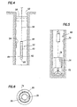
- Fig. 4 of the drawings which illustrates a wireline supported logging tool in an open hole filled with fluid.
- Fig. 5 shows a logging tool appended to a drill stem.
- the holes are shown vertical which is certainly not always the prevalent situation.
- the well will be drilled vertically at the surface and deviated at angles from the vertical.
- the logging tool 50 of the present disclosure is lowered into the well borehole 52. While part of the well may be cased, it has been omitted at the portion of the well adjacent to the logging tool 50 to show the typical circumstances.
- the drilled hole is rugose.
- Mud cake 54 a portion shown adjacent the tool 50, will build up on the borehole wall which somewhat reduces the abrasive nature of the borehole. Nevertheless, the rugose condition of the borehole abrades the exposed surfaces of the logging tool 50 suspended on the wireline 56. In this context, the tool may drag against the side; based on the weight of the tool, the angle of the well and other factors which are highly variant, some abrasive damage will accumulate. In general terms, the tool is lowered to the depth desired for the logging to be accomplished and retrieved. It is lowered in the column of fluid 58 standing in the well borehole. Again, Fig.
- the logging tool 50 incorporates some type of formation irradiation device 60, and a matched responsive sensor 62.
- the device 60 can be one or more coils in an array forming an induced EMF field in the adjacent formation. That typically is denoted as a transmitter coil (meaning one or more).
- the sensor 62 in that instance, is denoted as a receiver coil (one or more) and thus the coil system makes inductive logging measurements in the formations.
- the logging tool of this disclosure incorporates the shell 64 which is mounted between a pair of end located subs 66.
- the shell is formed in the manner disclosed above to thereby house the operative components of the logging tool.
- the hollow shell is mounted on appropriate end located subs 66 which are made by injection molding using the preferred resin of this disclosure.
- the surfaces of the shell 64 and the subs 66 are formed of the preferred resin fabricated as set forth above.
- Fig. 5 shows an alternate logging system.
- a logging while drilling system is disclosed. This involves a drill stem 68 suspended in a well borehole 70 for continued drilling.
- the drill stem 68 includes an appropriate length of drill pipe extending from a kelly at the surface with rotation imparted in the illustrated direction.
- a drill bit 72 advances the hole in response to rotation.
- drill collars 74 are incorporated. The drill collars are pipe joints with extra thick walls to enhance stiffness and weight, thereby maintaining the hole relatively straight. Mud is pumped down through the drill stem, flowing through the internal passage 76 in the drill collar 74 and out through the drill bit 72 and is returned to the surface in the annular space on the exterior of the drill stem.
- the drill stem includes one or more conventional drill collars 74.
- the lowermost drill collar includes logging while drilling (LWD) apparatus.
- LWD logging while drilling
- the significance of the present invention to the LWD system is brought out better in Fig. 6.
- the drill collar 74 is provided with a chamber 78 to enclose a measuring instrument.
- the measuring instrument can be the same instruments incorporated at 60 in Fig. 4. More specifically, some type of irradiation device and sensor are included, both being mounted in the chamber 78. In actuality, there may be several such chambers along the drill collar 74.
- the chambers are located so that they do not materially weaken the drill collar.
- the radiation is directed outwardly in the form of a beam or fully encircles the well borehole.
- An induction logging tool exemplifies a measuring system extending radially outwardly around the well borehole.
- the operative equipment for the measuring system is mounted and protected in the chamber 78, and the sleeve 80 is positioned around that.
- the sleeve 80 is constructed in accordance with the teachings of the present disclosure.
- the sleeve 80 is transparent to the radiation including EMF at any desired frequency.
- it isolates the chamber 78 from the fluids in the well.
- the fabricated cylindrical housing 80 is constructed in accordance with this disclosure. It has the advantages of operating at significant HPHT and yet is transparent to the EMF transmitted into the formations.
- Fig. 7 of the drawings shows a modified shell in accordance with this disclosure.
- the modified shell 82 and end located sub 66 shown in Fig. 7 are aptly used in a logging tool 50.
- a portion of the wall has been broken away to show, in cross-sectional view, shell construction.
- the shell or sleeve 82 is constructed with a first coil 84 wound within the wall thickness.
- a second coil 86 is spaced from it. It is also integrally fabricated in the wall. Again, one or more coils make up an induction logging tool transmitter and receive coil array.
- the wall might be about 0.50 inch in thickness and encloses one or more turns of the coils 84 and 86 in the wall.
- the gauge of wire is appropriate for the requirement.
- Fig. 7 additionally shows an internal recess 88 in the wall which recess mounts internally a sensor 90 which is responsive to the EMF or other irradiation triggered response back to the logging tool. Accordingly, the sensor can be on the inside surface, recessed or flush mounted as illustrated, and can also protrude above the inside surface. Both integrally formed sensors can be incorporated as well as those which are mounted after manufacture.
- the sensor construction shown in Fig. 7 can be deployed either in the wireline tool 50 of Fig. 4 or the LWD tool in Fig. 5.
Landscapes
- Geology (AREA)
- Life Sciences & Earth Sciences (AREA)
- Engineering & Computer Science (AREA)
- Physics & Mathematics (AREA)
- Mining & Mineral Resources (AREA)
- Geophysics (AREA)
- Environmental & Geological Engineering (AREA)
- Fluid Mechanics (AREA)
- General Life Sciences & Earth Sciences (AREA)
- Geochemistry & Mineralogy (AREA)
- Geophysics And Detection Of Objects (AREA)
- Compositions Of Macromolecular Compounds (AREA)
- Sampling And Sample Adjustment (AREA)
Description
- This invention concerns the fabrication and use of polyaryletherketone-based thermoplastic materials in the fabrication of oil field tools employed in downhole logging applications. By way of background, downhole logging tools are exposed to difficult environmental conditions. The average depth of wells drilled each year becomes deeper and deeper, both on shore and off shore. As the wells become deeper, the operating pressures and temperatures become higher. The open or uncased hole involves the cutting of a circular well borehole through the subsurface formations. After the drill bit has passed through each strata, it leaves a fairly rough, even abrasive surface. While the abrasive nature is reduced by the accumulation of a mud cake on the sidewall, the repeated travel of a logging tool along the well borehole produces abrasive wear. In addition, they are more often than not inclined from the vertical which leads to a substantial amount of abrasive wear on the logging tools. Logging tools are lowered into a well borehole, moved to the very bottom of the well. and then retrieved. This traverse of the full length of the well exposes the logging tool to abrasive contact with the open hole.
- Drilled wells can be extremely aggressive environments. Boreholes are often rugose and tend to be abrasive. Drilling muds, which are used to facilitate drilling, contain chemical additives which can degrade non-metallic materials. They are highly caustic with a pH ranging as high as 12.5. Other well fluids may include salt water, crude oil, carbon dioxide and hydrogen sulfide which are corrosive to many materials.
- Downhole conditions progressively become more hostile as depth increases. At depths of 5,000 to 8,000 meters, bottom hole temperatures (BHT) of 260°C and pressures of 170 MPa are often encountered. This exacerbates degradation of exposed logging tool materials.
- These deep well conditions of high pressure and high temperature (HPHT below) damage the external or exposed logging tool components. Internal electronics need to be protected from heat and external housings need to be upgraded. The most vulnerable materials are the plastic and composite materials which are exposed to caustic drilling mud and other corrosive well fluids. Some tools, such as those making electrical induction and magnetic resonance measurements, require these non-conductive, non-magnetic materials of construction in order to function properly. This requires materials which are essentially transparent to electromagnetic radiation and have magnetic permeability of 1.
- Ceramics generally are too brittle, i.e., a sharp impact may fracture the ceramic. The present disclosure sets forth a composite material system which is formed into the shell defining a downhole logging tool, and more particularly one which can operate at the prevailing BHT of 260 degrees C or greater. It enables the construction of an elongate cylindrical sleeve and connected, end located subs which comprises the major portion of the housing, as well as other non-metallic parts. The completed tool housing, and the contents within that housing are thus protected. On the interior, a pressure balance typically is achieved by raising the interior pressure inside the tool to approximate that on the exterior. Deep wells encounter pressures as high as 170 MPa or higher.
- Conventional plastics such as epoxies and phenolics perform adequately in conditions up to about 180 degrees C and 100 MPa. Under more extreme conditions however they fail prematurely. Many alternative materials have been evaluated and rejected for various reasons. For example, polyimides, polyetherimide ("ULTEM"), and polyamideimide ("TORLON") are well known for their excellent durability at high temperature. They, too, fail however in well fluids because their imide and amide linkages are subject to rapid hydrolytic degradation at high pH. Polyphenylene sulfide is water resistant but its crystalline melting point, 260 degrees C, is too low for this application.
- One class of material, polyaryletherketones, meets the demanding thermal and chemical requirements for this application. It has the desired high pressure, high temperature (HPHT) performance characteristics, and is also impervious to chemical attack by well and formation fluids. It provides structural rigidity and strength at HPHT conditions even in the presence of chemically active materials. For instance, there is always the risk of H2S invasion in a deep well. The shell of the subject invention is impervious to H2S. Moreover, it is both tough and resilient so that abrasive contact during movement in the well borehole does not damage or otherwise harm the apparatus. Finally, the apparatus is well able to enclose all the sensing components of an induction logging tool. The novel shell is substantially transparent to signal transmission from the logging tool and response from the formation.
European Pat. EP 505260A describes a source carrier including a sheath of thermoplastic material. However, the proposed carrier is designed for insertion and withdrawal from the internal passageway of a while-drilling tool, without being subjected to torsion or surface irregularities. Thus, the carrier is never directly disposed within the borehole or exposed to the borehole environment. U.S. Pat. No. 4,662,887 describes a human prosthetic device formed of polyaryletherketone polymer composition. U.S. Pat. No. 4,359,501 describes a fabric of woven monofilament threads comprised of polyaryletherketone polymers. - The present disclosure includes a sleeve which defines the housing for a logging tool supported both on a drill stem and wireline. Successful downhole housing shells, end connected subs, and a variety of other parts are made of polyaryletherketone-based thermoplastic materials to operate at HPHT conditions.
- The shell of the present disclosure is formed of a composite filament material. An induction logging tool shell is built from multiple plies of continuous filament wrapped around a mandrel. It is formed of a desired number of plies which are wrapped with a helical angle. Plies are wrapped both with practically no lead angle and also with changing angular bias to provide structural reinforcement. In addition to the shell, parts of various geometric shapes serving different functions can be manufactured by a variety of other methods.
- The induction logging tool utilizes an elongate sleeve supported between two end located subs. They are preferably formed by injection molding. The solid body mold is machined to the requisite shape and injection temperatures and pressures are applied to thereby mold the solid part. The preferred form utilizes randomly distributed chopped fibers of the same fiberglass material. They are generally randomly oriented in the flowing, adherent impregnating plastic raised to an appropriate temperature for injection molding. By applying the requisite pressure at the needed elevated temperature, the procedure molds the required shape. By appropriate construction of the cavity in the mold, machining of the formed part is held to a minimum. Typically, machining is required on the sealing surfaces to assure dimensional stability sufficient to enable the subs to be joined to the sleeve.
- This invention concerns utilization of the named materials in the fabrication of downhole logging tools for hostile environments. The materials are surprisingly robust at temperatures as high as 260 degrees C and pressures as high as 170 MPa while exposed to aggressive well fluids including drilling muds and H2S.
- The present invention thus includes parts formed by compression molding or by towpreg (a term defined below) application on a rotating mandrel and finish machining which are combined with appropriate design criteria dictated by the function of the downhole tool design to provide robust HPHT downhole tools. In both instances, the preferred resin is a polyaryletherketone resin with bonded glass fibers. This provides the requisite strength, electrical and magnetic characteristics while withstanding the pressures, temperature and corrosive fluids found in deep wells.
- The invention provides a downhole logging tool including a source or sensor for emitting or receiving a signal, respectively, within a subsurface formation and a housing which protects the source or sensor, characterized in that the housing comprises a shell (64) having an elongate body, said shell being made of polyaryletherketone thermoplastic resin.
- The advantages of the present invention will become apparent from the following description of the accompanying drawings. It is to be understood that the drawings are to be used for the purpose of illustration only, and not as a definition of the invention.
- In the drawings:
- FIG. 1 is a block diagram schematic showing a sequence of manufacturing steps for converting flexible yarn and impregnating resin into a towpreg wrapped on a rotating mandrel for forming an elongate cylindrical housing for an induction logging tool wherein the towpreg is wrapped around the mandrel to form the completed shell;
- Fig. 2 is an enlarged end view of a completed shell showing a portion of the wall and showing how it is formed of multiple layers of towpreg;
- Fig. 3 is a side view of a completed induction logging tool shell with portions broken away to illustrate multiple plies which form the shell and provide strength for it;
- Fig. 4 shows a wireline supported logging tool;
- Fig. 5 shows a drill stem supported logging while drilling tool;
- Fig. 6 is a sectional view of the tool of Fig. 5; and
- Fig. 7 is an isometric view through a sleeve showing a coil array supported by the sleeve.
-
- Attention is directed first to Fig. 1 of the drawings. A method of forming the preferred polyaryletherketone resin is set forth. As a preliminary step to making the multiple ply, multiple layer composite into an elongate tubular shell for a logging tool, a resin impregnated, fiber reinforced member called towpreg is formed. Examples of logging tools will be given later. In Fig. 1, the numeral 10 identifies a towpreg manufacturing and winding line. Several replicated spools of
fibers 12 are located so that they direct elongate strands which align the several fibers to form the disclosedtowpreg 20. An enlarged view of the towpreg is shown at 20. Thetowpreg 20 is formed to a specified width and thickness. The thickness is typically in the range of about 0.008" to about 0.02". The width is up to about 0.25". In general terms, it is extruded to form a rectangular cross-section. The shape is defined by a die which provides the requisite rectangular cross-sectional form. - The fibers are preferably a high temperature material provided by Owens Coming Fiberglass and is known as S2 fiberglass. The fiberglass is a high strength magnesium aluminosilicate glass. The glass fibers have a diameter ranging between about 10 and about 40 microns. They are preferably continuous filament, i.e., they are extremely long. Where they are grouped as a number of individual fibers making up an interlaced supply, the individual fibers have finite length but when interlaced, the collective length is substantially indefinite. Several sources of fibers are spooled to provide controllable tension and a desired level of prestress in them.
- The class of polyaryletherketones is disclosed in U.S. Patent 4,320,224 Structurally they are semi-crystalline, thermoplastic resins composed of the following repeat units:
- One type called PEEK is manufactured by Victrex USA, Inc. of West Chester, PA and disclosed in U.S. Patent 4,320,224. Its repeat unit is as follows:
- Another type called PEKK is marketed by Cytec Fiberite. It has the following repeat unit:
- A third type called ULTRAPEK was commercialized by BASF and has the repeat unit:
- The preferred plastic resin of this invention includes the three named resins where PEKK is most preferred. In the preferred embodiment of this invention, fiberglass embedded resin is wound to the desired size and may be later machined if required.
- Carbon black, up to about 2%, is added to the selected resin. Carbon black assists in the winding operation by enhancing heat absorption. It also reduces UV degradation in the finished product. Electrical properties are not degraded by a small amount of carbon granules. The selected resin is supplied at a specified viscosity and heated to an elevated temperature which is sufficient to effectively impregnate the
fibers 12. More specifically, this temperature is in the range of at least about 650°F and the most effective temperature is about 700°F or slightly there above. The finished product is in the range of about 33 to 43% by weight of resin. The remaining portion is made up of thefiber content 12. - The selected
resin 30 is delivered by apump 32 along with thefibers 12 to aheated extruder 36. Thetowpreg 20 is guided overtension rollers 40 to ashuttle drive 42 for winding on arotating mandrel 44. Severaladjacent heaters 46 apply heat externally and internally as needed to enable the tensionedmember 20 to form a "unitary" member from multiple windings in multiple plies. Figs 2 and 3 show different plies around a mandrel shaping an elongate cylinders. This includes one or more bottom plies 24 having no bias angle, and plies 26 and 28 with bias angles in opposite directions. Theouter ply 26 has essentially no bias angle. The representative shell, made to length and thickness, is described below on the logging tool. - There exist several different processes for the construction of continuous fiber-reinforced composite articles. These include filament winding, compression molding of stacked sheets, and resin transfer molding. For polyaryletherketone resins like the ones claimed herein, the most preferred method is filament winding. The first step is to impregnate S2 fiberglass tow with the resin as described for example in U.S. Patent 4,549,920. The tow comprises a plurality of filaments, the filaments having a diameter preferably up to 24 microns. The tensioned tow is passed continuously through a heated nip at which point it is spread and molten resin is injected so as to substantially completely wet all the filaments with resin. The impregnated tow, called towpreg, has the form of flat tape. It is then traverse wound on a rotating mandrel from a traversing carriage as described for example in U.S. Patent 5,160,561. Consolidation is achieved by appropriate heating to melt each successive ply so that it fuses to the previous ply before cooling and solidifying. The resulting monolithic structure has all the properties required of a shell for a downhole logging tool.
- Plies are added at an angle (from the axis of the mandrel) which can vary between 0 and 90°. Mechanical properties in the x, y and z directions depend on the angular construction which is therefore specified according to engineering requirements. Typical downhole logging tools require tubular shapes with diameters ranging from 2 to 20 cm., wall thicknesses from 0.2 to 2 cm. and lengths up to six meters. The filament winding process described above is well-suited to produce tubular shapes having these dimensions.
- Before this invention, shells for downhole logging tools rated to 260°C comprised a thermoset phenolic resin reinforced with fiberglass fabric. Shells were fabricated by impregnating woven glass fabric with a phenolic resin to give a prepreg. The prepreg was wrapped around a mandrel to the desired thickness then cured under heat and pressure. The resulting thermoset composite shells were extremely unreliable; sometime they performed as designated but more often they failed by cracking.
- Shells were certified by immersing them in water at 270°C and 179 MPa hydrostatic pressure for a few hours in a high pressure well. A high percentage of shells failed during a single excursion in a test well. Shells which survived the well test often failed after a single well-logging job. Failures were traced to internal defects caused by the shrinkage of the resin during curing. The thermoplastic composite shells of this invention do not have this disadvantage and therefore do not fail in well tests.
- Another way to compare composite shells is to test their properties before and after well tests. To that end a method was developed to measure "ring flexural properties". One-inch rings sliced from shells were compressed diametrically between opposing flat platens of a test machine until failure. From the stress/strain curve it is possible to calculate the modulus and strength of rings using published formulas.
- A series of tests were conducted in which rings were exposed in water or oil at temperatures ranging from 176 to 260°C and pressures to 179 Mpa for periods up to 12 hours. Representative rings were subjected to the ring flexural tests before and after exposure. Phenolic/fiberglass rings showed excessive losses in ring flexural strength. In a typical test, flexural strength declined from 140 MPa to 78.6 Mpa after only one hour at 232°C and one hour at 260°C.
- For comparison, filament-wound rings made of fiberglass-reinforced PEKK resin were tested but under more severe conditions. After six hours in water at 270°C and 145 Mpa pressure the ring flexural strength was 206 Mpa and the flexural modulus was 36 Gpa.
- Random lengths of chopped fiberglass are randomly mixed with the preferred resin, and are injected at appropriate temperature and pressure by an injection molding machine into a mold to define a shaped sub. As before, up to about 2% of carbon black distributed throughout the resin is permissible. The fibers are more or less randomly oriented. The fibers provide significant structural integrity and modify the CTE somewhat. They can comprise about 30% or 40% by weight of the mixture. After injection molding, a component is provided having desirable characteristics which will become more apparent on discussion of typical applications in a well borehole below.
- Attention is directed to Fig. 4 of the drawings which illustrates a wireline supported logging tool in an open hole filled with fluid. By contrast, Fig. 5, to be discussed below, shows a logging tool appended to a drill stem. As will be understood in both circumstances, the holes are shown vertical which is certainly not always the prevalent situation. Commonly, the well will be drilled vertically at the surface and deviated at angles from the vertical. By gravity, the logging tool 50 of the present disclosure is lowered into the
well borehole 52. While part of the well may be cased, it has been omitted at the portion of the well adjacent to the logging tool 50 to show the typical circumstances. The drilled hole is rugose.Mud cake 54, a portion shown adjacent the tool 50, will build up on the borehole wall which somewhat reduces the abrasive nature of the borehole. Nevertheless, the rugose condition of the borehole abrades the exposed surfaces of the logging tool 50 suspended on thewireline 56. In this context, the tool may drag against the side; based on the weight of the tool, the angle of the well and other factors which are highly variant, some abrasive damage will accumulate. In general terms, the tool is lowered to the depth desired for the logging to be accomplished and retrieved. It is lowered in the column offluid 58 standing in the well borehole. Again, Fig. 4 has been simplified but provides a relatively simple context in which the logging tool is exposed to HPHT in the presence of highly caustic fluid. There may be H2S present, perhaps entrained in thewell fluid 58. The logging tool 50 incorporates some type offormation irradiation device 60, and a matchedresponsive sensor 62. Thedevice 60 can be one or more coils in an array forming an induced EMF field in the adjacent formation. That typically is denoted as a transmitter coil (meaning one or more). Thesensor 62, in that instance, is denoted as a receiver coil (one or more) and thus the coil system makes inductive logging measurements in the formations. Another example is a neutron generator which transmits neutrons into the formation and thesensor 62 would then be a radiation detector such as a NaI detector. Without regard to theparticular irradiation device 60, the matchedsensor 62 receives and responds appropriately and forms a logging signal useful in determining the nature of the formations along the well borehole. The logging tool of this disclosure incorporates theshell 64 which is mounted between a pair of end locatedsubs 66. The shell is formed in the manner disclosed above to thereby house the operative components of the logging tool. The hollow shell is mounted on appropriate end locatedsubs 66 which are made by injection molding using the preferred resin of this disclosure. The surfaces of theshell 64 and thesubs 66 are formed of the preferred resin fabricated as set forth above. - Fig. 5 shows an alternate logging system. In Fig. 5, a logging while drilling system is disclosed. This involves a
drill stem 68 suspended in awell borehole 70 for continued drilling. Thedrill stem 68 includes an appropriate length of drill pipe extending from a kelly at the surface with rotation imparted in the illustrated direction. At the lower end of the drill stem, adrill bit 72 advances the hole in response to rotation.Several drill collars 74 are incorporated. The drill collars are pipe joints with extra thick walls to enhance stiffness and weight, thereby maintaining the hole relatively straight. Mud is pumped down through the drill stem, flowing through theinternal passage 76 in thedrill collar 74 and out through thedrill bit 72 and is returned to the surface in the annular space on the exterior of the drill stem. The drill stem includes one or moreconventional drill collars 74. Of important significance to the present disclosure, preferably the lowermost drill collar includes logging while drilling (LWD) apparatus. The significance of the present invention to the LWD system is brought out better in Fig. 6. There, thedrill collar 74 is provided with achamber 78 to enclose a measuring instrument. The measuring instrument can be the same instruments incorporated at 60 in Fig. 4. More specifically, some type of irradiation device and sensor are included, both being mounted in thechamber 78. In actuality, there may be several such chambers along thedrill collar 74. The chambers are located so that they do not materially weaken the drill collar. In general terms, the radiation is directed outwardly in the form of a beam or fully encircles the well borehole. An induction logging tool exemplifies a measuring system extending radially outwardly around the well borehole. In any event, the operative equipment for the measuring system is mounted and protected in thechamber 78, and thesleeve 80 is positioned around that. Thesleeve 80 is constructed in accordance with the teachings of the present disclosure. Thus, thesleeve 80 is transparent to the radiation including EMF at any desired frequency. In addition, it isolates thechamber 78 from the fluids in the well. The fabricatedcylindrical housing 80 is constructed in accordance with this disclosure. It has the advantages of operating at significant HPHT and yet is transparent to the EMF transmitted into the formations. - Attention is now directed to Fig. 7 of the drawings which shows a modified shell in accordance with this disclosure. The modified
shell 82 and end locatedsub 66 shown in Fig. 7 are aptly used in a logging tool 50. A portion of the wall has been broken away to show, in cross-sectional view, shell construction. The shell orsleeve 82 is constructed with afirst coil 84 wound within the wall thickness. Asecond coil 86 is spaced from it. It is also integrally fabricated in the wall. Again, one or more coils make up an induction logging tool transmitter and receive coil array. As representative dimensions, the wall might be about 0.50 inch in thickness and encloses one or more turns of thecoils coils coil 84 is the transmitter coil and thecoil 86 is the receiver coil for an induction logging array. As required, the coils making up the array can be partially or wholly embedded in the wall. Fig. 7 additionally shows aninternal recess 88 in the wall which recess mounts internally asensor 90 which is responsive to the EMF or other irradiation triggered response back to the logging tool. Accordingly, the sensor can be on the inside surface, recessed or flush mounted as illustrated, and can also protrude above the inside surface. Both integrally formed sensors can be incorporated as well as those which are mounted after manufacture. The sensor construction shown in Fig. 7 can be deployed either in the wireline tool 50 of Fig. 4 or the LWD tool in Fig. 5. - While the foregoing is directed to the preferred embodiment, the scope is determined by the claims which follow:
Claims (20)
- A downhole logging tool (50) including a source (60) or sensor (62) for emitting or receiving a signal, respectively, within a borehole (52) traversing a subsurface formation, and a tool housing which protects said source or sensor, characterized in that the tool housing comprises a radiation transparent shell (64) having an elongate body, said shell comprised of polyaryletherketone thermoplastic resin.
- The logging tool of claim 1 wherein said resin is a linear aromatic polymer having the following repeat units:
- The logging tool of claim 2 wherein said shell comprises a fiber-reinforced composite sleeve.
- The logging tool of claim 3 wherein said shell includes multiple plies of fiber in said resin and wherein said plies have specified angular bias positions.
- The logging tool of claim 4 wherein said shell comprises a specified wall thickness of said composite, and the fiber is fiberglass.
- The logging tool of claim 5 wherein said resin has been blended with a material which enhances heat absorption and reduces UV degradation.
- The logging tool of claim 6 wherein the material is carbon black.
- The logging tool of claim 1 wherein said source and said sensor are both disposed within said housing.
- The logging tool of claim 2 wherein said source and said sensor are both disposed within said housing.
- The logging tool of claim 3 wherein said source and said sensor are both disposed within said housing.
- The logging tool of claim 1 wherein said shell is connected to a sub at an end thereof.
- The logging tool of claim 11 wherein said sub comprises a linear aromatic polymer having the following repeat units:
- The logging tool of claim 12 wherein said sub comprises a molded solid body including plural, discontinuous fibers.
- The logging tool of claim 11 wherein said shell comprises a fiber-reinforced composite sleeve.
- The logging tool of claim 14 wherein said logging tool shell comprises
a thermoplastic resin selected from the group consisting of - The logging tool of claim 1 wherein the shell surrounds a drill collar.
- The logging tool of claim 16 wherein said source or said sensor is mounted on said drill collar.
- The logging tool of claim 16 wherein said resin is a linear aromatic polymer having the following repeat units:
- The logging tool of claim 1 wherein said source or said sensor is a coil mounted on the inner side of said shell.
- The logging tool of claim 1 wherein said source or said sensor is partially or wholly embedded within said shell, and the shell comprises a fiber-reinforced composite sleeve.
Applications Claiming Priority (2)
| Application Number | Priority Date | Filing Date | Title |
|---|---|---|---|
| US26218 | 1998-02-19 | ||
| US09/026,218 US6084052A (en) | 1998-02-19 | 1998-02-19 | Use of polyaryletherketone-type thermoplastics in downhole tools |
Publications (2)
| Publication Number | Publication Date |
|---|---|
| EP0942147A1 EP0942147A1 (en) | 1999-09-15 |
| EP0942147B1 true EP0942147B1 (en) | 2003-04-16 |
Family
ID=21830538
Family Applications (1)
| Application Number | Title | Priority Date | Filing Date |
|---|---|---|---|
| EP99400259A Expired - Lifetime EP0942147B1 (en) | 1998-02-19 | 1999-02-04 | Use of polyaryletherketone-type thermoplastics in downhole tools |
Country Status (7)
| Country | Link |
|---|---|
| US (1) | US6084052A (en) |
| EP (1) | EP0942147B1 (en) |
| JP (1) | JPH11281753A (en) |
| CN (1) | CN1131924C (en) |
| AU (1) | AU727402B2 (en) |
| ID (1) | ID21992A (en) |
| NO (1) | NO326353B1 (en) |
Families Citing this family (46)
| Publication number | Priority date | Publication date | Assignee | Title |
|---|---|---|---|---|
| US6865933B1 (en) * | 1998-02-02 | 2005-03-15 | Murray D. Einarson | Multi-level monitoring well |
| US6300762B1 (en) * | 1998-02-19 | 2001-10-09 | Schlumberger Technology Corporation | Use of polyaryletherketone-type thermoplastics in a production well |
| US6429653B1 (en) * | 1999-02-09 | 2002-08-06 | Baker Hughes Incorporated | Method and apparatus for protecting a sensor in a drill collar |
| US6325108B1 (en) * | 1999-06-21 | 2001-12-04 | David S. Bettinger | Prestressed composite cryogenic piping |
| US6573722B2 (en) | 2000-12-15 | 2003-06-03 | Schlumberger Technology Corporation | Method and apparatus for cancellation of borehole effects due to a tilted or transverse magnetic dipole |
| WO2002079606A1 (en) * | 2001-03-29 | 2002-10-10 | Greene, Tweed Of Deleware, Inc. | Method for producing sealing and anti-extrusion components for use in downhole tools and components produced thereby |
| US6712153B2 (en) * | 2001-06-27 | 2004-03-30 | Weatherford/Lamb, Inc. | Resin impregnated continuous fiber plug with non-metallic element system |
| EP1421413A2 (en) * | 2001-08-03 | 2004-05-26 | Baker Hughes Incorporated | A method and apparatus for a multi-component induction instrument measuring system |
| US6677756B2 (en) | 2001-08-03 | 2004-01-13 | Baker Hughes Incorporated | Multi-component induction instrument |
| US6644421B1 (en) | 2001-12-26 | 2003-11-11 | Robbins Tools, Inc. | Sonde housing |
| US7463035B2 (en) * | 2002-03-04 | 2008-12-09 | Baker Hughes Incorporated | Method and apparatus for the use of multicomponent induction tool for geosteering and formation resistivity data interpretation in horizontal wells |
| US6930652B2 (en) * | 2002-03-29 | 2005-08-16 | Schlumberger Technology Corporation | Simplified antenna structures for logging tools |
| US6667620B2 (en) | 2002-03-29 | 2003-12-23 | Schlumberger Technology Corporation | Current-directing shield apparatus for use with transverse magnetic dipole antennas |
| US6690170B2 (en) | 2002-03-29 | 2004-02-10 | Schlumberger Technology Corporation | Antenna structures for electromagnetic well logging tools |
| US6933726B2 (en) * | 2003-08-05 | 2005-08-23 | Schlumberger Technology Corporation | Apparatus and methods for reducing borehole current effects |
| US7040156B2 (en) * | 2003-08-21 | 2006-05-09 | William Crockford | Flexible membrane encapsulated strain measurement instrument and method of manufacture |
| US7026813B2 (en) * | 2003-09-25 | 2006-04-11 | Schlumberger Technology Corporation | Semi-conductive shell for sources and sensors |
| US7046112B2 (en) * | 2004-01-26 | 2006-05-16 | Halliburton Energy Services, Inc. | Logging tool induction coil form |
| US7525315B2 (en) | 2004-04-01 | 2009-04-28 | Schlumberger Technology Corporation | Resistivity logging tool and method for building the resistivity logging tool |
| US7719282B2 (en) * | 2004-04-14 | 2010-05-18 | Baker Hughes Incorporated | Method and apparatus for mulit-component induction instrument measuring system for geosteering and formation resistivity data interpretation in horizontal, vertical and deviated wells |
| US7913806B2 (en) * | 2005-05-10 | 2011-03-29 | Schlumberger Technology Corporation | Enclosures for containing transducers and electronics on a downhole tool |
| US8256565B2 (en) * | 2005-05-10 | 2012-09-04 | Schlumberger Technology Corporation | Enclosures for containing transducers and electronics on a downhole tool |
| US9267332B2 (en) | 2006-11-30 | 2016-02-23 | Longyear Tm, Inc. | Impregnated drilling tools including elongated structures |
| CA2671193C (en) * | 2006-11-30 | 2012-04-24 | Kristian Drivdahl | Fiber-containing diamond-impregnated cutting tools |
| US9540883B2 (en) | 2006-11-30 | 2017-01-10 | Longyear Tm, Inc. | Fiber-containing diamond-impregnated cutting tools and methods of forming and using same |
| GB0703021D0 (en) * | 2007-02-16 | 2007-03-28 | Specialised Petroleum Serv Ltd | |
| US8244473B2 (en) * | 2007-07-30 | 2012-08-14 | Schlumberger Technology Corporation | System and method for automated data analysis and parameter selection |
| MX2010001461A (en) | 2007-08-10 | 2010-03-15 | Schlumberger Technology Bv | Ruggedized neutron shields. |
| US7723989B2 (en) * | 2007-08-31 | 2010-05-25 | Schlumberger Technology Corporation | Transducer assemblies for subsurface use |
| US8720539B2 (en) * | 2007-09-27 | 2014-05-13 | Schlumberger Technology Corporation | Modular power source for subsurface systems |
| US8123888B2 (en) * | 2009-04-28 | 2012-02-28 | Schlumberger Technology Corporation | Fiber reinforced polymer oilfield tubulars and method of constructing same |
| US8590646B2 (en) * | 2009-09-22 | 2013-11-26 | Longyear Tm, Inc. | Impregnated cutting elements with large abrasive cutting media and methods of making and using the same |
| US8657894B2 (en) | 2011-04-15 | 2014-02-25 | Longyear Tm, Inc. | Use of resonant mixing to produce impregnated bits |
| US8816689B2 (en) * | 2011-05-17 | 2014-08-26 | Saudi Arabian Oil Company | Apparatus and method for multi-component wellbore electric field Measurements using capacitive sensors |
| US9869135B1 (en) | 2012-06-21 | 2018-01-16 | Rfg Technology Partners Llc | Sucker rod apparatus and methods for manufacture and use |
| US10351686B2 (en) | 2013-03-13 | 2019-07-16 | Baker Hughes, A Ge Company, Llc | Methods of forming modified thermoplastic structures for down-hole applications |
| US9213124B2 (en) * | 2013-03-22 | 2015-12-15 | Oliden Technology, Llc | Restorable antennae apparatus and system for well logging |
| US12553331B2 (en) * | 2013-06-12 | 2026-02-17 | Well Resolutions Technology | Systems and methods for an array of different downhole sensors in a single tool body |
| WO2014201297A2 (en) | 2013-06-12 | 2014-12-18 | Well Resolutions Technology | Apparatus and methods for making azimuthal resistivity measurements |
| MX2016003973A (en) | 2013-10-30 | 2016-06-02 | Halliburton Energy Services Inc | Downhole formation fluid sampler having an inert sampling bag. |
| CA2973407C (en) | 2015-01-12 | 2022-04-12 | Longyear Tm, Inc. | Drilling tools having matrices with carbide-forming alloys, and methods of making and using same |
| CA3067809C (en) | 2017-08-02 | 2022-04-19 | Halliburton Energy Services, Inc. | Wear sleeve |
| WO2019032363A1 (en) * | 2017-08-09 | 2019-02-14 | Geodynamics, Inc. | Molded tool and a method of manufacture |
| CN108676109B (en) * | 2018-05-08 | 2021-02-09 | 中国石油大学(华东) | A kind of nanofluid for interwell tracer, its preparation method and its application |
| US11434747B2 (en) * | 2020-07-24 | 2022-09-06 | Baker Hughes Oilfield Operations Llc | Down-hole tools comprising layers of materials and related methods |
| US11459744B2 (en) * | 2021-01-04 | 2022-10-04 | United States Of America As Represented By The Secretary Of The Navy | In-pipe storm water filter |
Family Cites Families (18)
| Publication number | Priority date | Publication date | Assignee | Title |
|---|---|---|---|---|
| EP0001879B2 (en) * | 1977-09-07 | 1989-11-23 | Imperial Chemical Industries Plc | Thermoplastic aromatic polyetherketones, a method for their preparation and their application as electrical insulants |
| US4549920A (en) | 1981-07-28 | 1985-10-29 | Imperial Chemical Industries, Plc | Method for impregnating filaments with thermoplastic |
| US4359501A (en) * | 1981-10-28 | 1982-11-16 | Albany International Corp. | Hydrolysis resistant polyaryletherketone fabric |
| GB8415265D0 (en) * | 1984-06-15 | 1984-07-18 | Ici Plc | Device |
| US4714509A (en) * | 1984-07-02 | 1987-12-22 | E. I. Dupont De Nemours And Company | Method and apparatus for laying down tapes |
| US4816556A (en) * | 1985-02-22 | 1989-03-28 | E. I. Du Pont De Nemours And Company | Ordered polyetherketones |
| GB8617989D0 (en) * | 1986-07-23 | 1986-10-01 | Ici Plc | Polymer composition |
| US5160561A (en) * | 1987-09-11 | 1992-11-03 | E. I. Du Pont De Nemours And Company | Method for winding a plurality of lengths of thermoplastic resin impregnated yarns using a heated guide eye |
| US5160568A (en) * | 1987-09-11 | 1992-11-03 | E. I. Du Pont De Nemours And Company | Apparatus including a heated guide eye for winding a plurality of lengths of thermoplastic resin impregnated yarns |
| CA1323350C (en) * | 1987-09-11 | 1993-10-19 | Fiberite, Inc. | Apparatus and method for winding a plurality of lengths of thermoplastic resin impregnated yarns and product thereof |
| CA2020905A1 (en) * | 1989-10-27 | 1991-04-28 | Roy F. Wright | Thermoplastic resin compositions and methods |
| US5363929A (en) * | 1990-06-07 | 1994-11-15 | Conoco Inc. | Downhole fluid motor composite torque shaft |
| IL98381A0 (en) * | 1990-06-25 | 1992-07-15 | Du Pont | Apparatus and method for winding fiber reinforced thermoplastic resin tow and the product thereof |
| ES2077724T3 (en) * | 1990-07-12 | 1995-12-01 | Basf Ag | STABILIZED POLYARYLETHERETONE MOLDING MASSES. |
| GB9020462D0 (en) * | 1990-09-19 | 1990-10-31 | Filters For Industry Ltd | Abrasive segments |
| DE4039924A1 (en) * | 1990-12-14 | 1992-06-17 | Hoechst Ag | ALLOYS FROM PART CRYSTALINE AND AMORPHOUS POLYARYLETHERKETONES |
| US5184692A (en) * | 1991-03-18 | 1993-02-09 | Schlumberger Technology Corporation | Retrievable radiation source carrier |
| US5871052A (en) * | 1997-02-19 | 1999-02-16 | Schlumberger Technology Corporation | Apparatus and method for downhole tool deployment with mud pumping techniques |
-
1998
- 1998-02-19 US US09/026,218 patent/US6084052A/en not_active Expired - Lifetime
-
1999
- 1999-01-19 AU AU12145/99A patent/AU727402B2/en not_active Ceased
- 1999-01-27 ID IDP990057A patent/ID21992A/en unknown
- 1999-02-03 JP JP11026330A patent/JPH11281753A/en active Pending
- 1999-02-04 EP EP99400259A patent/EP0942147B1/en not_active Expired - Lifetime
- 1999-02-18 NO NO19990744A patent/NO326353B1/en not_active IP Right Cessation
- 1999-02-23 CN CN99102369A patent/CN1131924C/en not_active Expired - Fee Related
Also Published As
| Publication number | Publication date |
|---|---|
| US6084052A (en) | 2000-07-04 |
| JPH11281753A (en) | 1999-10-15 |
| EP0942147A1 (en) | 1999-09-15 |
| CN1131924C (en) | 2003-12-24 |
| CN1231378A (en) | 1999-10-13 |
| AU727402B2 (en) | 2000-12-14 |
| AU1214599A (en) | 1999-09-02 |
| NO990744L (en) | 1999-08-20 |
| NO326353B1 (en) | 2008-11-17 |
| NO990744D0 (en) | 1999-02-18 |
| ID21992A (en) | 1999-08-19 |
Similar Documents
| Publication | Publication Date | Title |
|---|---|---|
| US6084052A (en) | Use of polyaryletherketone-type thermoplastics in downhole tools | |
| US6300762B1 (en) | Use of polyaryletherketone-type thermoplastics in a production well | |
| US9121260B2 (en) | Electrically non-conductive sleeve for use in wellbore instrumentation | |
| US20020007945A1 (en) | Composite coiled tubing with embedded fiber optic sensors | |
| US5933945A (en) | Composite coiled tubing apparatus and methods | |
| CA2758672C (en) | Fiber reinforced polymer oilfield tubulars and method of constructing same | |
| US10724299B2 (en) | Reinforced directional drilling assemblies and methods of forming same | |
| CA2952494C (en) | Composite bow centralizer | |
| CA2305148C (en) | Composite spoolable tube with sensor | |
| EP0361639B1 (en) | Bar-like molding made of fiber-reinforced plastic material and method of manufacturing the same | |
| CA2435351C (en) | Replaceable antennas for wellbore apparatus | |
| CA2824118C (en) | Composite bow centralizer | |
| EP3193169B1 (en) | Fluid sensor comprising a resonant cavity made of an electrically conductive composite material | |
| CA2482384C (en) | Semi-conductive shell for sources and sensors | |
| WO2013095754A1 (en) | Insulation structure for well logging instrument antennas | |
| WO1998045635A9 (en) | Composite structures having high containment strength | |
| US7671597B2 (en) | Composite encased tool for subsurface measurements | |
| US20260002422A1 (en) | Method of using degradable glass fibers for downhole tools | |
| US12331613B2 (en) | Composite downhole tools | |
| MXPA06006644A (en) | Composite encased tool for subsurface measurements |
Legal Events
| Date | Code | Title | Description |
|---|---|---|---|
| PUAI | Public reference made under article 153(3) epc to a published international application that has entered the european phase |
Free format text: ORIGINAL CODE: 0009012 |
|
| AK | Designated contracting states |
Kind code of ref document: A1 Designated state(s): GB NL |
|
| AX | Request for extension of the european patent |
Free format text: AL;LT;LV;MK;RO;SI |
|
| 17P | Request for examination filed |
Effective date: 20000223 |
|
| AKX | Designation fees paid |
Free format text: GB NL |
|
| REG | Reference to a national code |
Ref country code: DE Ref legal event code: 8566 |
|
| 17Q | First examination report despatched |
Effective date: 20010122 |
|
| GRAG | Despatch of communication of intention to grant |
Free format text: ORIGINAL CODE: EPIDOS AGRA |
|
| GRAG | Despatch of communication of intention to grant |
Free format text: ORIGINAL CODE: EPIDOS AGRA |
|
| GRAH | Despatch of communication of intention to grant a patent |
Free format text: ORIGINAL CODE: EPIDOS IGRA |
|
| GRAH | Despatch of communication of intention to grant a patent |
Free format text: ORIGINAL CODE: EPIDOS IGRA |
|
| GRAA | (expected) grant |
Free format text: ORIGINAL CODE: 0009210 |
|
| AK | Designated contracting states |
Designated state(s): GB NL |
|
| REG | Reference to a national code |
Ref country code: GB Ref legal event code: FG4D |
|
| PLBE | No opposition filed within time limit |
Free format text: ORIGINAL CODE: 0009261 |
|
| STAA | Information on the status of an ep patent application or granted ep patent |
Free format text: STATUS: NO OPPOSITION FILED WITHIN TIME LIMIT |
|
| 26N | No opposition filed |
Effective date: 20040119 |
|
| PG25 | Lapsed in a contracting state [announced via postgrant information from national office to epo] |
Ref country code: NL Free format text: LAPSE BECAUSE OF NON-PAYMENT OF DUE FEES Effective date: 20040901 |
|
| NLV4 | Nl: lapsed or anulled due to non-payment of the annual fee |
Effective date: 20040901 |
|
| PGFP | Annual fee paid to national office [announced via postgrant information from national office to epo] |
Ref country code: GB Payment date: 20130130 Year of fee payment: 15 |
|
| GBPC | Gb: european patent ceased through non-payment of renewal fee |
Effective date: 20140204 |
|
| PG25 | Lapsed in a contracting state [announced via postgrant information from national office to epo] |
Ref country code: GB Free format text: LAPSE BECAUSE OF NON-PAYMENT OF DUE FEES Effective date: 20140204 |