EP0940260A1 - Adaptateur pour système d'alimentation en encre - Google Patents
Adaptateur pour système d'alimentation en encre Download PDFInfo
- Publication number
- EP0940260A1 EP0940260A1 EP99301568A EP99301568A EP0940260A1 EP 0940260 A1 EP0940260 A1 EP 0940260A1 EP 99301568 A EP99301568 A EP 99301568A EP 99301568 A EP99301568 A EP 99301568A EP 0940260 A1 EP0940260 A1 EP 0940260A1
- Authority
- EP
- European Patent Office
- Prior art keywords
- ink
- connector
- contacts
- printing system
- post
- Prior art date
- Legal status (The legal status is an assumption and is not a legal conclusion. Google has not performed a legal analysis and makes no representation as to the accuracy of the status listed.)
- Granted
Links
Images


Classifications
-
- B—PERFORMING OPERATIONS; TRANSPORTING
- B41—PRINTING; LINING MACHINES; TYPEWRITERS; STAMPS
- B41J—TYPEWRITERS; SELECTIVE PRINTING MECHANISMS, i.e. MECHANISMS PRINTING OTHERWISE THAN FROM A FORME; CORRECTION OF TYPOGRAPHICAL ERRORS
- B41J2/00—Typewriters or selective printing mechanisms characterised by the printing or marking process for which they are designed
- B41J2/005—Typewriters or selective printing mechanisms characterised by the printing or marking process for which they are designed characterised by bringing liquid or particles selectively into contact with a printing material
- B41J2/01—Ink jet
- B41J2/17—Ink jet characterised by ink handling
- B41J2/175—Ink supply systems ; Circuit parts therefor
- B41J2/17503—Ink cartridges
- B41J2/17556—Means for regulating the pressure in the cartridge
-
- B—PERFORMING OPERATIONS; TRANSPORTING
- B41—PRINTING; LINING MACHINES; TYPEWRITERS; STAMPS
- B41J—TYPEWRITERS; SELECTIVE PRINTING MECHANISMS, i.e. MECHANISMS PRINTING OTHERWISE THAN FROM A FORME; CORRECTION OF TYPOGRAPHICAL ERRORS
- B41J2/00—Typewriters or selective printing mechanisms characterised by the printing or marking process for which they are designed
- B41J2/005—Typewriters or selective printing mechanisms characterised by the printing or marking process for which they are designed characterised by bringing liquid or particles selectively into contact with a printing material
- B41J2/01—Ink jet
- B41J2/17—Ink jet characterised by ink handling
- B41J2/175—Ink supply systems ; Circuit parts therefor
- B41J2/17503—Ink cartridges
- B41J2/17506—Refilling of the cartridge
- B41J2/17509—Whilst mounted in the printer
-
- B—PERFORMING OPERATIONS; TRANSPORTING
- B41—PRINTING; LINING MACHINES; TYPEWRITERS; STAMPS
- B41J—TYPEWRITERS; SELECTIVE PRINTING MECHANISMS, i.e. MECHANISMS PRINTING OTHERWISE THAN FROM A FORME; CORRECTION OF TYPOGRAPHICAL ERRORS
- B41J2/00—Typewriters or selective printing mechanisms characterised by the printing or marking process for which they are designed
- B41J2/005—Typewriters or selective printing mechanisms characterised by the printing or marking process for which they are designed characterised by bringing liquid or particles selectively into contact with a printing material
- B41J2/01—Ink jet
- B41J2/17—Ink jet characterised by ink handling
- B41J2/175—Ink supply systems ; Circuit parts therefor
- B41J2/17503—Ink cartridges
- B41J2/17513—Inner structure
-
- B—PERFORMING OPERATIONS; TRANSPORTING
- B41—PRINTING; LINING MACHINES; TYPEWRITERS; STAMPS
- B41J—TYPEWRITERS; SELECTIVE PRINTING MECHANISMS, i.e. MECHANISMS PRINTING OTHERWISE THAN FROM A FORME; CORRECTION OF TYPOGRAPHICAL ERRORS
- B41J2/00—Typewriters or selective printing mechanisms characterised by the printing or marking process for which they are designed
- B41J2/005—Typewriters or selective printing mechanisms characterised by the printing or marking process for which they are designed characterised by bringing liquid or particles selectively into contact with a printing material
- B41J2/01—Ink jet
- B41J2/17—Ink jet characterised by ink handling
- B41J2/175—Ink supply systems ; Circuit parts therefor
- B41J2/17503—Ink cartridges
- B41J2/1752—Mounting within the printer
- B41J2/17523—Ink connection
-
- B—PERFORMING OPERATIONS; TRANSPORTING
- B41—PRINTING; LINING MACHINES; TYPEWRITERS; STAMPS
- B41J—TYPEWRITERS; SELECTIVE PRINTING MECHANISMS, i.e. MECHANISMS PRINTING OTHERWISE THAN FROM A FORME; CORRECTION OF TYPOGRAPHICAL ERRORS
- B41J2/00—Typewriters or selective printing mechanisms characterised by the printing or marking process for which they are designed
- B41J2/005—Typewriters or selective printing mechanisms characterised by the printing or marking process for which they are designed characterised by bringing liquid or particles selectively into contact with a printing material
- B41J2/01—Ink jet
- B41J2/17—Ink jet characterised by ink handling
- B41J2/175—Ink supply systems ; Circuit parts therefor
- B41J2/17503—Ink cartridges
- B41J2/17543—Cartridge presence detection or type identification
- B41J2/17546—Cartridge presence detection or type identification electronically
-
- B—PERFORMING OPERATIONS; TRANSPORTING
- B41—PRINTING; LINING MACHINES; TYPEWRITERS; STAMPS
- B41J—TYPEWRITERS; SELECTIVE PRINTING MECHANISMS, i.e. MECHANISMS PRINTING OTHERWISE THAN FROM A FORME; CORRECTION OF TYPOGRAPHICAL ERRORS
- B41J2/00—Typewriters or selective printing mechanisms characterised by the printing or marking process for which they are designed
- B41J2/005—Typewriters or selective printing mechanisms characterised by the printing or marking process for which they are designed characterised by bringing liquid or particles selectively into contact with a printing material
- B41J2/01—Ink jet
- B41J2/17—Ink jet characterised by ink handling
- B41J2/175—Ink supply systems ; Circuit parts therefor
- B41J2/17503—Ink cartridges
- B41J2/17543—Cartridge presence detection or type identification
- B41J2/1755—Cartridge presence detection or type identification mechanically
-
- B—PERFORMING OPERATIONS; TRANSPORTING
- B41—PRINTING; LINING MACHINES; TYPEWRITERS; STAMPS
- B41J—TYPEWRITERS; SELECTIVE PRINTING MECHANISMS, i.e. MECHANISMS PRINTING OTHERWISE THAN FROM A FORME; CORRECTION OF TYPOGRAPHICAL ERRORS
- B41J2/00—Typewriters or selective printing mechanisms characterised by the printing or marking process for which they are designed
- B41J2/005—Typewriters or selective printing mechanisms characterised by the printing or marking process for which they are designed characterised by bringing liquid or particles selectively into contact with a printing material
- B41J2/01—Ink jet
- B41J2/17—Ink jet characterised by ink handling
- B41J2/175—Ink supply systems ; Circuit parts therefor
- B41J2/17503—Ink cartridges
- B41J2/17553—Outer structure
-
- B—PERFORMING OPERATIONS; TRANSPORTING
- B41—PRINTING; LINING MACHINES; TYPEWRITERS; STAMPS
- B41J—TYPEWRITERS; SELECTIVE PRINTING MECHANISMS, i.e. MECHANISMS PRINTING OTHERWISE THAN FROM A FORME; CORRECTION OF TYPOGRAPHICAL ERRORS
- B41J2/00—Typewriters or selective printing mechanisms characterised by the printing or marking process for which they are designed
- B41J2/005—Typewriters or selective printing mechanisms characterised by the printing or marking process for which they are designed characterised by bringing liquid or particles selectively into contact with a printing material
- B41J2/01—Ink jet
- B41J2/17—Ink jet characterised by ink handling
- B41J2/175—Ink supply systems ; Circuit parts therefor
- B41J2/17566—Ink level or ink residue control
-
- B—PERFORMING OPERATIONS; TRANSPORTING
- B41—PRINTING; LINING MACHINES; TYPEWRITERS; STAMPS
- B41J—TYPEWRITERS; SELECTIVE PRINTING MECHANISMS, i.e. MECHANISMS PRINTING OTHERWISE THAN FROM A FORME; CORRECTION OF TYPOGRAPHICAL ERRORS
- B41J2/00—Typewriters or selective printing mechanisms characterised by the printing or marking process for which they are designed
- B41J2/005—Typewriters or selective printing mechanisms characterised by the printing or marking process for which they are designed characterised by bringing liquid or particles selectively into contact with a printing material
- B41J2/01—Ink jet
- B41J2/17—Ink jet characterised by ink handling
- B41J2/175—Ink supply systems ; Circuit parts therefor
- B41J2/17596—Ink pumps, ink valves
-
- B—PERFORMING OPERATIONS; TRANSPORTING
- B41—PRINTING; LINING MACHINES; TYPEWRITERS; STAMPS
- B41J—TYPEWRITERS; SELECTIVE PRINTING MECHANISMS, i.e. MECHANISMS PRINTING OTHERWISE THAN FROM A FORME; CORRECTION OF TYPOGRAPHICAL ERRORS
- B41J25/00—Actions or mechanisms not otherwise provided for
- B41J25/34—Bodily-changeable print heads or carriages
-
- B—PERFORMING OPERATIONS; TRANSPORTING
- B41—PRINTING; LINING MACHINES; TYPEWRITERS; STAMPS
- B41J—TYPEWRITERS; SELECTIVE PRINTING MECHANISMS, i.e. MECHANISMS PRINTING OTHERWISE THAN FROM A FORME; CORRECTION OF TYPOGRAPHICAL ERRORS
- B41J2/00—Typewriters or selective printing mechanisms characterised by the printing or marking process for which they are designed
- B41J2/005—Typewriters or selective printing mechanisms characterised by the printing or marking process for which they are designed characterised by bringing liquid or particles selectively into contact with a printing material
- B41J2/01—Ink jet
- B41J2/17—Ink jet characterised by ink handling
- B41J2/175—Ink supply systems ; Circuit parts therefor
- B41J2/17566—Ink level or ink residue control
- B41J2002/17569—Ink level or ink residue control based on the amount printed or to be printed
-
- B—PERFORMING OPERATIONS; TRANSPORTING
- B41—PRINTING; LINING MACHINES; TYPEWRITERS; STAMPS
- B41J—TYPEWRITERS; SELECTIVE PRINTING MECHANISMS, i.e. MECHANISMS PRINTING OTHERWISE THAN FROM A FORME; CORRECTION OF TYPOGRAPHICAL ERRORS
- B41J2/00—Typewriters or selective printing mechanisms characterised by the printing or marking process for which they are designed
- B41J2/005—Typewriters or selective printing mechanisms characterised by the printing or marking process for which they are designed characterised by bringing liquid or particles selectively into contact with a printing material
- B41J2/01—Ink jet
- B41J2/17—Ink jet characterised by ink handling
- B41J2/175—Ink supply systems ; Circuit parts therefor
- B41J2/17566—Ink level or ink residue control
- B41J2002/17573—Ink level or ink residue control using optical means for ink level indication
-
- B—PERFORMING OPERATIONS; TRANSPORTING
- B41—PRINTING; LINING MACHINES; TYPEWRITERS; STAMPS
- B41J—TYPEWRITERS; SELECTIVE PRINTING MECHANISMS, i.e. MECHANISMS PRINTING OTHERWISE THAN FROM A FORME; CORRECTION OF TYPOGRAPHICAL ERRORS
- B41J2/00—Typewriters or selective printing mechanisms characterised by the printing or marking process for which they are designed
- B41J2/005—Typewriters or selective printing mechanisms characterised by the printing or marking process for which they are designed characterised by bringing liquid or particles selectively into contact with a printing material
- B41J2/01—Ink jet
- B41J2/17—Ink jet characterised by ink handling
- B41J2/175—Ink supply systems ; Circuit parts therefor
- B41J2/17566—Ink level or ink residue control
- B41J2002/17576—Ink level or ink residue control using a floater for ink level indication
Definitions
- This invention relates in general to providing an adaptive in supply in lieu of an original equipment ink cartridge for an inkjet printing system, particularly wherein the ink cartridge has a memory device that exchanges information with the printing system.
- ink-jet printing system has a printhead mounted to a carriage that is moved back and forth over a print media, such as paper. As the printhead passes over appropriate locations on the print media, a control system activates the printhead to eject ink drops onto the printing surface and form desired images and characters. To work properly, such printing systems must have a reliable supply of ink for the printhead.
- ink-jet printing system uses an ink supply that is mounted to and moves with the carriage.
- the ink supply is replaceable separately from the printhead.
- the printhead and ink supply together form an integral unit that is replaced once the ink in the ink supply is depleted.
- Another category of printing system uses ink supplies that are not located on the carriage.
- One type replenishes the printhead intermittently.
- the printhead will travel to a stationary reservoir periodically for replenishment.
- Another type referred to as a replaceable off-axis ink supply, has a replaceable ink cartridge or container connected to the printhead by a fluid conduit.
- the ink cartridge has a fluid reservoir filled with ink and located within a housing.
- the reservoir has a fluid coupling mechanism for coupling the reservoir to the printing system so that ink may flow from the reservoir to the printhead.
- the reservoir is sometimes pressurized in some manner to provide a reliable high flow rate supply of ink to the printhead.
- a replaceable off-axis cartridge which has a memory device mounted to the housing.
- an electrical connection between the printing system and the memory device is established.
- This electrical connection allows for the exchange of information between the printing system and the memory.
- the memory device stores information that is utilized by the printing system to ensure high print quality. This information is provided to the printing system automatically when the cartridge is mounted to the printing system. The exchange of information assures compatibility of the cartridge with the printing system.
- the stored information includes helpful information, such as the date when the cartridge was first installed on a printing system. This installation date can be used to deduce how long the cartridge has been installed and hence whether the ink contained in the cartridge may be beyond shelf life.
- the stored information further prevents the use of the cartridge after it is depleted of ink.
- Operating a printing system when the reservoir has been depleted of ink can destroy the printhead.
- the memory devices concerned with this application are updated with data from the printhead concerning the amount of ink left in the reservoir as it is being used.
- the printing system will read information from the memory device indicative of the reservoir volume.
- the printing system estimates ink usage and updates the memory device to indicate how much ink is left in the cartridge.
- this type of memory device can store data indicative of an out of ink condition.
- these cartridges are typically discarded and a new cartridge along with a new memory device is installed.
- ink containers described in the parent application have fixed volumes of deliverable ink that have been provided for printing systems based generally on ink usage rate requirements of a particular user.
- printing systems users have a wide variety of ink usage rates that may change over time.
- ink containers having these volumes require a relatively high ink container replacement rate. This can be especially disruptive for print jobs which are left to run overnight.
- Extended continuous use of printing systems causes ink containers to run out of ink during a print job. If the printing system does not shut down during an "ink out" condition, the printhead or the printing system itself may be permanently damaged.
- the adaptive ink delivery systems include ink reservoirs of varying configuration and size that are capable of accommodating a variety of ink use rates.
- Each adaptive ink delivery system also has an electrical connector and an information storage device which are suitable for the various ink use rates.
- the information storage device may be a memory device or an emulation circuit that provides the functionality of a memory device but may have a different structure.
- the adaptive ink delivery systems allow one to locate the ink reservoir and/or the information storage device remotely from the printing system.
- Figure 1 is a schematic representation of a printing system showing an ink container which forms a fluid interconnect and an electrical interconnect with the printing system.
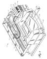
- Figure 2 is an isometric view of a preferred embodiment of the printing system represented in Fig. 1.
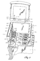
- Figure 3 is an ink supply receiving station of the type used in the printer of Fig. 2 shown broken away with an ink supply positioned for insertion into the ink supply receiving station.
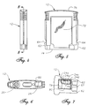
- Figure 4 is a side view of the ink container of Figure 1.
- Figure 5 is a front view of the ink container of Figure 1.
- Figure 6 is a bottom view of the ink container of Figure 1.
- Figure 7 is an enlarged bottom view of the ink container of Figure 1, showing detail of the electrical interconnect portion of the ink container.
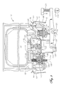
- Figure 8 is a sectional side view of the ink container of Figure 1, taken along the line 8-8 in Figure 4 just prior to engaging the ink-jet printing system of Figure 1.
- Figure 9 is a sectional side view of the ink container of Figure 1 taken along the line 8-8 in Figure 4 and shown fully engaged with the ink-jet printing system of Figure 1.
- Figure 10 shows the electrical interface between the ink container and the ink receiving station of Fig. 3 shown greatly enlarged.
- Figure 11 is a bottom view of a first embodiment of an adaptive ink container constructed in accordance with the invention to be used in place of the original equipment ink container shown in Figures 1-10.
- Figure 12 is a bottom view of a second embodiment of an adaptive ink container constructed in accordance with the invention.
- Figure 13 is a front view of the embodiment of Figure 11.
- Figure 14 is a side view of a third embodiment of an adaptive ink container constructed in accordance with the invention.
- Figure 15 is a side view of a fourth embodiment of an adaptive ink container constructed in accordance with the invention.
- Figure 16 is a side view of a fifth embodiment of an adaptive ink container constructed in accordance with the invention.
- Figure 17 is an enlarged side view of an electrical connector adapter for connecting a remote memory device to the printing system of Figures 1-10.
- Figure 18 is a front view of a sixth embodiment of an adaptive ink delivery system constructed in accordance with the invention.
- Figure 19 is a front view of a seventh embodiment of an adaptive ink container constructed in accordance with the invention.
- Figure 20 is a front view of a eighth embodiment of an adaptive ink container constructed in accordance with the invention.
- Figure 21 is a front view of a ninth embodiment of an adaptive ink container for larger volumes of ink and is constructed in accordance with the invention.
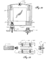
- Figure 22 is a front view of a tenth embodiment of an adaptive ink container constructed in accordance with the invention.
- Figure 23 is a partial sectional view of a eleventh embodiment of an adaptive ink container constructed in accordance with the invention.
- the present invention comprises adapters and methods for altering the volume of ink and the corresponding informational requirements supplied to a printing system
- the invention may be more clearly understood with a thorough discussion of the printing system and an initial ink container.
- Figure 1 illustrates a portion of an ink-jet printing system 10 having an ink cartridge or container 12.
- the ink-jet printing system 10 includes an ink container receiving station 14, an ink-jet printhead 16, and a print controller 18. Printing is accomplished by the ejection of ink from the printhead 16 under the control of print controller 18. Printhead 16 is connected to the controller 18 by link 19 for controlling ejection of ink. Ink is provided to the printhead 16 by way of a fluid conduit 21, which joins the printhead 16 to the receiving station 14.
- Ink container 12 includes a fluid outlet 20 that communicates with a fluid reservoir 22.
- Ink container 12 also includes electrical terminals or contacts 24 that communicate with an information storage device 26 such as a memory device.
- Fluid outlet 20 and electrical contacts 24 allow ink container 12 to interconnect with a fluid inlet 28 and electrical contacts 30, respectively, on receiving station 14.
- Receiving station 14 enables ink to be transferred from fluid reservoir 22 to printhead 16 via fluid conduit 21.
- receiving station 14 allows the transfer of information between information storage device 26 and print controller 18 via a link 32.
- Each ink container 12 has unique ink container-related aspects that are represented in the form of data provided by information storage device 26.
- This data is provided from ink container 12 to printing system 10 via information storage device 26 automatically without requiring the user to reconfigure printing system 10 for the particular ink container 12 installed.
- the data provided may be indicative of the ink container manufacturer identity, type of ink, and date code of the ink container 12.
- the data provided may include system parameters, such as system coefficients and service mode.
- Printing system 10 monitors the level of deliverable ink in ink container 12 via information storage device 26.
- Information storage device 26 stores volume information indicative of the level of deliverable ink in ink container 12.
- Printing system 10 updates this volume information by altering memory device 26 and queries this volume information by receiving data from memory device 26.
- communication including transfer of data between printing system 10 and information storage device 26 is accomplished in serial fashion along the single data line 24d relative to ground (Fig. 7).
- the volume information includes the following: (1) initial supply size data in a write protected portion of memory, (2) coarse ink level data stored in write once portion of memory, and (3) fine ink level data stored in a write/erase portion of memory.
- the initial supply size data is indicative of the amount of deliverable ink initially present in ink container 12.
- the coarse ink level data includes a number of write once bits that each correspond to some fraction of the deliverable ink initially present in ink container 12. In a first preferred embodiment, eight coarse ink level bits each correspond to one eighth of the deliverable ink initially in ink container 12. In a second preferred embodiment, to be used in the discussion that follows, seven coarse ink level bits each correspond to one eighth of the deliverable ink initially present in ink container 12 and one coarse ink level bit corresponds to an out of ink condition. However, more or less coarse bits can be used, depending on the accuracy desired for a coarse ink level counter.
- the fine ink level data is indicative of a fine bit binary number that is proportional to a fraction of one eighth of the volume of the deliverable ink initially present in ink container 12.
- the entire range of the fine bit binary number is equivalent to one coarse ink level bit. This will be further explained below.
- Printing system 10 reads the initial supply size data and calculates the amount or volume of deliverable ink initially present in ink container 12.
- An estimated drop volume ejected by the printhead 16 is determined by printing system 10 by reading parameters and/or performing calculations. Using the initial volume of deliverable ink in ink container 12 and the estimated drop volume of printhead 16, the printing system 10 calculates the fraction of the initial deliverable ink volume that each drop represents. This enables the printing system 10 to monitor the fraction of the initial volume of deliverable ink remaining in ink container 12.
- printing system 10 While printing, printing system 10 maintains a drop count equal to the number of ink drops have been ejected by printhead 16. After printing system 10 has printed a small amount, typically one page, it converts the drop count to a number of increments or decrements of the fine bit binary number. This conversion utilizes the fact that the entire range of the fine bit binary number corresponds to one eighth of the initial volume of deliverable ink in ink container 12. Each time the fine bit binary number is fully decremented or incremented, the printing system 10 writes to one of the coarse ink level bits to "latch down" the bit.
- Printing system 10 periodically queries the coarse and fine ink level bits to determine the fraction of the initial deliverable ink that is remaining in ink container 12. Printing system 10 can then provide a "gas gauge” or other indication to a user of printing system 10 that is indicative of the ink level in ink container 12. In a preferred embodiment, the printing system provides a "low ink warning" when the sixth (second to last) coarse ink level bit is set. Also in a preferred embodiment, the printing system sets the eighth (last) coarse ink level bit when the ink container 12 is substantially depleted of ink. This last coarse ink level bit is referred to as an "ink out” bit. Upon querying the coarse ink level bits, the printing system interprets a "latched down" ink out bit as an "ink out” condition for ink container 12.
- Printing system 10 includes a tray 40 for holding a paper supply.
- a sheet of paper from tray 40 is fed into printing system 10 using a sheet feeder (not shown).
- the paper passes through a print zone 42 whereupon a scanning carriage 44 containing one or more printheads 16 is scanned across the sheet for printing a swath of ink thereon.
- the sheet of paper is stepped through the print zone 42 as the scanning carriage 44 prints a series of swaths of ink to form images thereon.
- the sheet is positioned into an output tray 46.
- the positioning of paper supply 40 and output tray 46 can vary depending on the particular sheet feed mechanism used.
- Scanning carriage 44 slides through the print zone 42 on a scanning mechanism that includes a slide rod 48.
- a positioning means such as a coded strip (not shown) is used in conjunction with a photo detector for precisely positioning scanning carriage 44.
- a stepper motor (not shown), connected to scanning carriage 44 using a conventional drive belt and pulley arrangement, is used for transporting scanning carriage 44 across print zone 42.
- a ribbon cable (not shown) carries electrical signals to the scanning carriage 44 for selectively energizing the printheads 16 ( Figures 1 and 2). As the printheads 16 are selectively energized, ink of a selected color is ejected onto the print media as scanning carriage 44 passes through print zone 42.
- Each ink container 12 has its own electrical contacts 24 and fluid outlet 20 (Figure 3).
- Ink containers 12 may be referred to as an off-axis ink supply since the ink supply is spaced from a scan axis defined by scanning carriage 44.
- ink containers 12 are typically separate ink containers for each color with a container for black ink.
- ink container 12 for the embodiment shown in Figure 2 is an ink container 54 for black ink, an ink container 56 for yellow ink, an ink container 58 for magenta ink, and an ink container 60 for cyan ink.
- Receiving station 14 contains mechanical, fluid and electrical interfaces for each ink container 12. Ink passes through the fluid interfaces in receiving station 14, fluid conduits 21 and then to printheads 16 on print scanning carriage 44.
- receiving station 14 has a first end 14a and a second end 14b with inward facing first and second walls, respectively.
- a plurality of the fluid inlets 28 are located near first end 14a for providing ink to a plurality of corresponding printheads 16 via conduits 21 ( Figure 1).
- a plurality of the electrical contacts 30 is located near the second end 14b for providing electrical signals to controller 18 ( Figure 1).
- Each fluid inlet 28 is located as far from electrical contacts 30 as possible to prevent contamination of contacts 30 with ink from fluid inlets 28.
- ink container 12 has aligning ribs 62 on each side edge. Aligning ribs 62 mate with slots 66 ( Figure 3) on receiving station 14 to assist in aligning ink container 12 for insertion into receiving station 14. Aligning ribs 62 and slots 66 also provide a keying function to ensure that ink container 12 contains ink having the proper parameters, such as color and ink compatibility with printing system 10. Ink container 12 also has latch shoulders 64 on each side edge, as shown in Figure 3, which are engaged by resilient latches 68 mounted on the sidewalls of receiving station 14.
- ink container 12 is aligned and inserted into receiving station 14, latches 68 on receiving station 14 engage corresponding latch shoulders 64 on ink container 12. Insertion of ink container 12 into receiving station 14 forms both electrical and fluid interconnects between contacts 24 and 30, and ports 20 and 28, respectively.
- receiving station 14 has four separate electrical connector posts 70, one for each of the cartridges 12.
- the four electrical contacts 30 for each cartridge 12 are mounted to each electrical connector post 70, as shown in Figure 10.
- Electrical connector posts 70 are substantially free to float in a plane that is substantially perpendicular with respect to a direction of insertion of ink container 12 into receiving station 14.
- the direction of insertion of ink container 12 is indicated as the z-axis, and the plane in which connector post 70 floats is indicated by the x and y-axes, or the xy-plane.
- Contacts 30 extend laterally from one side of post 70 along a direction parallel to the x-axis, and are arrayed along the y-axis.
- Connector post 70 includes a tapered leading portion 71 that tapers in an upward direction, or along the z-axis. Contacts 30 are outwardly spring biased from connector post 70.
- ink container 12 includes an outer surface or housing 72 having a leading edge or end 74 and a trailing edge or end 76 relative to the direction of insertion of ink container 12 into receiving station 14 ( Figure 3).
- there are four terminals or contacts 24 on the ink container 24a for ground, 24b for clocking signals, 24c for power, and 24d for input and output data.
- Contacts 24 are located in a small cavity 80 on a lower side of housing 72 adjacent to leading edge 74. Cavity 80 has four perpendicular sidewalls 79.
- contacts 24 are metal conductive layers disposed on a substrate of electrical insulation material such as epoxy and fiberglass.
- traces or leads 81 are disposed on substrate 78, each extending from one of the contacts 24.
- Memory device 26 is mounted to substrate 78, and the terminals of memory device 26 are joined to the traces 81. This places memory device 26 in electrical continuity with contacts 24.
- Adhesive (not shown) is used to encapsulate memory device 26 after its terminals are bonded to traces 81.
- the substrate, along with contacts 24 and memory device 26, is bonded by adhesive or swaged to a sidewall of cavity 80. Electrical contacts 24 are positioned along the z-axis when ink container 12 is oriented for engagement with receiving station 14.
- the entrance to cavity 80 is sized to be small enough to reduce the possibility of fingers from entering cavity 80.
- the proper sizing of the entrance is important for preventing contamination of contacts 24 during handling of ink container 12.
- Cavity 80 closely receives one of the connector posts 70. As ink container 12 is inserted into printing system 10, resilient contacts 30 are compressed against contacts 24 to form a low resistance electrical connection between printing system 10 and memory device 26.
- tapered portion 71 engages cavity 80 to provide alignment between connector post 70 and cavity 80 such that connector post 70 can partially pass into it.
- tapered portion 71 engages the contact surface of a first side and the opposing surface on a second side, aligning connector post 70 by providing an aligning force in the x-direction.
- the perpendicular sidewalls 79 also engage tapered portion 79 to provide alignment in the y-direction. Being movably mounted in x and y directions, connector post 70 moves in these directions to provide proper alignment between contacts 24 and 30.
- spring-loaded contacts 30 provide a contact force along the x-direction which is opposed by an opposing force exerted by connector post 70. Because connector post 70 can float in the x and y-directions, the contact force and opposing force are substantially equal and opposite, such that they provide a substantially minimal or zero net force on connector post 70 and on ink container 12. Minimizing such a lateral force is important, since a lateral x or y force exerted on ink container 12 will tend to interfere with a proper fluidic connection between fluid outlet 20 on the one hand and fluid inlet 28 on the other.
- fluid outlet 20 includes a hollow cylindrical tube or boss 90 that extends downward from ink container chassis 92.
- Boss 90 has an upper end that is fluidically connected to reservoir 22 and a lower end that supports a septum 100.
- Conduit 94 is joined between boss 90 and ink reservoir 22.
- a spring 96 and sealing ball 98 are located within boss 90 and held in place by a compliant septum 100 and a crimp cover 102.
- Septum 100 is a resilient seal and has a slit that extends through it. Spring 96 biases sealing ball 98 against septum 100 to form a seal.
- Fluid inlet 28 on receiving station 14 includes a cylindrical housing 104 surrounding a needle 106.
- Needle 106 has a blunt upper end, a bore (not shown) and a lateral hole 110 that leads from the bore.
- the lower end of needle 106 is connected to conduit 21 ( Figures 1-2) for providing ink to printhead 16.
- a sliding collar 108 surrounds needle 106 and is upwardly biased by a spring 114.
- Collar 108 has a compliant sealing portion with an exposed upper surface and an inner surface in direct contact with the needle 106. While in the upper position of Figure 3, collar 108 seals hole 110 in needle 106. When pushed down to the lower position of Figure 9, hole 110 of needle 106 inserted through the slit in septum 100 to establish fluid communication between conduit 21 and ink reservoir 22.
- Boss 90 is dimensionally sized to be closely received within cylindrical housing 104. The tolerance between the outer diameter of boss 90 and inner diameter of housing 104 assures that the septum 100 can properly engage needle 106. The length of boss 90 must be sufficient for crimp cover 102 to push sliding collar 108 to a lower position to allow ink to flow into port 110 of needle 106.
- ink container 12 When ink container 12 is installed into receiving station 14, the crimp cover 102 of boss 90 slides within housing 104 to align septum 100 with respect to needle 106. Needle 106 is then received by septum 100 and pushes ball 98 to a disengaged position. As needle 106 inserts into septum 100, crimp cover 102 depresses collar 108 so that hole 110 is exposed to receive fluid as described above. In the installed position, springs 68 engage latching portion 64 to firmly hold ink container 12 in place.
- Pump 115 is described in co-pending U.S. Patent Application serial number 08/869,151, filed June 4, 1997, attorney docket number 10970908-1, entitled "Ink Container Configured For Use With A Printing Device Having An Out-Of-Ink Sensing System", all of which material is hereby incorporated by reference.
- Pump 115 includes movable plate covered by a diaphragm 117. Diaphragm 117 is biased downward by a coil spring 118. Pump 115 has a chamber 116 with an outlet 119 and inlet 120 leading to reservoir 22.
- a valve 121 is located at inlet 120 to prevent outward flow of ink from pump chamber 116 but allow inward flow from reservoir 22.
- An actuator 122 is reciprocally mounted in printing system station 14 for engaging diaphragm 117. Actuator 122 is pivotally connected to a lever 123. A spring 124 acts on lever 123, which pivots at fulcrum 125 and urges actuator 122 upward.
- a cam 126 is mounted below lever 123 and is rotatable by a shaft 127. Rotating shaft 127 to an engaged position causes cam 126 to overcome the force of compression spring 124 and move actuator 122 downward to draw in more ink from reservoir 22.
- a flag 128 extends downward from the bottom of actuator 122 where it is received within an optical detector 129.
- Optical detector 129 directs a beam of light from one leg toward a sensor positioned on the other leg. When actuator 122 is in an uppermost position, flag 128 raises above the beam of light, allowing it to reach the sensor and activate detector 129. In any lower position, flag 128 blocks the beam of light.
- actuator 122 Prior to installing ink container 12, actuator 122 will be in its uppermost position, being urged upward by spring 124. After installation, diaphragm 117 will move actuator 122 to the lowermost position. As ink is depleted from the pump chamber, actuator 122 will move upward due to the force of spring 124. When enough ink is depleted from the pump chamber to position actuator 122 at its uppermost position, flag 128 will no longer block the beam of light which can then reach the optical detector 129. In response, the printing system will initiate a refresh cycle. Shaft 127 will rotate cam 126, pulling actuator 122 back to its lowermost position. Diaphragm 117 will move downward due to spring 118, drawing a new supply of ink from reservoir 22 through inlet 120 into pump chamber 116. After a predetermined time interval, shaft 127 rotates cam 126 back to its disengaged position.
- Figures 11-17 illustrate alternative electrical coupling devices for coupling information storage device 26 to the contacts 30 associated with supply station 14.
- a first embodiment has a signal and ink housing or cartridge 131 that is similar to that of cartridge 12.
- Cartridge 131 has a fluid outlet 133 and an electrical connector 135.
- Outlet 133 and connector 135 extend downward from a lower side of cartridge 131.
- Outlet 133 is substantially identical to outlet 20, described above.
- Connector 135 comprises a first planar vertical member 137 having a rigid support 139 with inner and outer surfaces.
- a plurality of electrical contacts 141 are mounted to the inner surface of support 139.
- Contacts 141 are flat, parallel strips which are substantially similar to previously described contacts 24.
- Contacts 141 are connected to a memory device that is similar to memory device 26.
- Connector 135 also comprises a second planar vertical member 143 with inner and outer surfaces.
- Member 143 is parallel to and spaced apart from member 137 by a distance that is approximately equal to a width of connector post 70 ( Figure 10).
- the inner surface of member 143 is flat and faces in an opposite direction relative to contacts 141.
- member 143 also serves as a rigid support.
- a pump assembly 145 is shown depending from a lower side of cartridge 131.
- Pump assembly 145 is stroked by actuator 122 ( Figure 9) in the same manner as pump 115. If a pump is not utilized, it would be necessary to provide a retainer device that prevents actuator 122 from moving to its uppermost position. This avoids an out of ink signal occurring due to the position of actuator 122. That device could be the portion ofthe housing surrounding pump 145 that can be referred to as an "actuator engagement portion".
- cartridge 131 is secured to printing system 10 in a substantially similar manner as cartridge 12.
- outlet 133 engages fluid inlet 28 and connector 135 engages contacts 30 on printing system 10.
- Connector post 70 ( Figure 10) slides between member 137 and member 143 as cartridge is moved downward into an engaged position.
- Contacts 141 are forced to slidably engage contacts 30 as member 143 presses against a backside of connector post 70.
- Pump 145 is engaged by actuator 122 ( Figure 9).
- the memory device contained within cartridge 131 provides ink container-related data to printing system 10.
- a second embodiment of an adaptive ink supply is shown in Figure 12.
- a signal and ink cartridge 151 is substantially similar to cartridge 131.
- Cartridge 151 comprises a fluid outlet 153 and an electrical connector 155 having planar vertical members 157, 163. Electrical contacts 161 are mounted to the inner surface of member 157.
- member 163 is generally parallel to member 157, the inner surface of member 163 differs from that of member 143.
- the inner surface of member 163 is slightly concave in shape rather than flat.
- cartridge 151 is identical to cartridge 131.
- cartridge 151 is secured to printing system 10 in a substantially similar manner as cartridge 131.
- Cartridge 151 is lowered onto receiving station 14 ( Figure 3), as outlet 153 engages fluid inlet 28 and connector 155 engages contacts 30.
- Connector post 70 ( Figure 10) slides between member 157 and member 163.
- Contacts 161 are forced to slidably engage contacts 30 as member 163 presses against a backside of connector post 70.
- the concave inner surface of member 163 serves to "capture" assembly 116 between members 157 and 163 and better align contacts 161 with contacts 30.
- FIG. 14-16 Third, fourth and fifth embodiments of adaptive electrical connectors are depicted in Figures 14-16. Like the previous two embodiments, these three embodiments have fluid outlets and connector members which extend downward from a lower side of the cartridge.
- cartridge 171 Figure 14
- the contacts 179 of connector 175 are not mounted to a surface. Contacts 179 are curved springs that extend downward directly from cartridge 171.
- cartridge 171 has a backside "support member” which comprises a plurality of curved bias springs 177 that extend downward individually from cartridge 171. Collectively, contacts 179 are parallel to springs 177.
- the fourth embodiment ( Figure 15) differs from the third embodiment in that backside support member 181 is straight and rigid rather than curved springs.
- Member 181 is a rigid upstanding member that functions in the same way as member 143 of Fig. 11.
- the fifth embodiment ( Figure 16) differs from the third embodiment in that the electrical contacts associated with ink container 12 are mounted to an inside surface of rigid support member 183.
- Rigid support member 183 is similar to support member 137 of Fig. 11.
- the third embodiment is operated by lowering cartridge 171 into receiving station 14 ( Figure 3).
- a fluid outlet (not shown) engages fluid inlet 28 and connector post 70 ( Figure 10) slides between springs 177 and contacts 179.
- Contacts 179 are forced against and slidably engage contacts 30 as springs 177 press against the backside of connector post 70.
- the fourth and fifth embodiments operate very similarly to the third embodiment.
- An adaptive electrical connector assembly 191 is depicted in Figure 17.
- An ink container (not shown) having a fluid outlet similar to fluid outlet 20 ( Figure 1) is used in conjunction with connector assembly 191.
- An electrical adapter or connector assembly 191 is separate or detached from the ink container housing, but is used to communicate information to printing system 10 concerning the fluid delivered by the fluid outlet.
- Assembly 191 comprises an electrical connector 193 that connects to an information storage device or emulation device 196.
- Emulation device 196 is an electronic circuit that functions similar to memory device 26. As described above for the memory device of cartridge 131, it exchanges information with printing system 10 ( Figure 1). For example, emulation device 196 may provide information regarding the volume of ink, the type of ink, color, etc.
- Emulation device 196 provides information signals indicative of volume and type of ink to controller 18 when connector 195 is connected to connector post 70. In a preferred embodiment, these signals are interpreted by the controller 18 to be indicative of the initial ink supply size, the coarse ink level and the fine ink level. Each time the signal indicative of the fine ink level reaches an extreme, the coarse ink level signal is incremented in emulation device 196 in response.
- Emulation device 196 thus may be a near duplicate of information storage device 26.
- emulation device 196 may be a signal-providing circuit that enables printing system 10 to operate whenever a new ink supply is provided. If desired, emulation device 196 may be configured to provide information to printing system 10 which enables it to operate regardless of the actual condition of the ink in the ink reservoir. In addition, emulation device 196 may be located remotely from or immediately adjacent to printing system 10.
- Assembly 191 also comprises an adapter connector 195.
- Adapter connector 195 may be of any one of the embodiments of Figures 10-16 and is provided for attachment to connector post 70.
- adapter connector 195 has a rigid body with spaced-apart vertical sides 197 that oppose each other.
- a plurality of contacts 198 is mounted to an inner surface of one of sides 197.
- a flexible cable 199 extends between electrical connector 193 and adapter connector 195.
- adapter connector 195 is attached to connector post 70 so that contacts 198 slidably engage contacts 30.
- Vertical sides 197 maintain pressure between contacts 198 and 30.
- the ink supply is then connected to receiving station 14 ( Figure 3) as described for the embodiments described below.
- these ink supply embodiments utilize external assembly 191 to communicate information to printing system 10.
- connection method between adapter connector 195 and contacts 30 would be to provide permanent electrical coupling between contacts 198 and contacts 30.
- the contacts may be joined with a method such as soldering, welding, or mechanically affixing.
- This permanent connection method can also apply to the electrical contacts shown in figures 10-16.
- cable 199 may be permanently attached to an information storage device or emulator, eliminating the need for connector 229.
- FIG. 18 shows alternative adaptive ink supply systems.
- a sixth embodiment of the invention is designed to provide much larger volumes of ink than the previous ink containers while maintaining the ability to supply the necessary ink information to the printing system.
- This embodiment has a conduit 201 that replaces the housing of the previous embodiments.
- Conduit 201 extends from a remotely located ink supply or reservoir 202 and has a fluid outlet 203 that is fluidically connected to fluid inlet 28 in receiving station 14.
- Ink reservoir 202 may be located remotely from or not immediately adjacent to printing system 10.
- Ink reservoir 202 can be very large relative to ink container 12 since it is not constrained by receiving station 14 geometry. Additionally, it can be conveniently located.
- Outlet 203 is constructed similar to fluid outlet 20 ( Figures 8 and 9) which is described above.
- a retainer plate 204 is fastened to printing system station 14, depressing actuator 122 to a lower position. Retainer 204 prevents actuator 122 from moving to its uppermost position, which would result in an erroneous out of ink signal, as explained previously.
- This embodiment also comprises an electrical connector assembly 205 which is similar to assembly 191 discussed with respect to Fig. 17.
- assembly 205 includes an electrical connector (not shown) affixed to one end of a flexible cable 209.
- the electrical connector may be connected to an information storage or emulation device like the one described for Figure 17.
- An adapter connector 211 which is similar connector 195 discussed with respect to Fig. 17 is located on the opposite end of cable 209.
- adapter connector 211 is attached to connector post 70 ( Figure 10) so that its contacts slidably engage the printing system electrical contacts to allow an information storage device or emulator to provide data to printing system 10.
- Conduit 201 is mounted into receiving station 14 ( Figure 3) by fluidically connecting fluid outlet 203 to fluid inlet 28.
- Retainer plate 204 is secured to printing system station 14.
- this embodiment utilizes separate electrical and large external fluid subassemblies to communicate ink and information to printing system 10.
- a housing 221 has a reservoir of ink 223 and a fluid outlet 225 similar to fluid outlet 20 ( Figures 8 and 9) which connects to inlet 28 in receiving station 14 ( Figure 2).
- a pump assembly 235 may depend from cartridge housing 221 for engagement by actuator 122 ( Figure 18). If a pump is not desired, an actuator engagement portion 235 of housing 221 may serve as a retainer to prevent actuator 122 from moving to its uppermost position.
- housing 221 includes guiding and latching features for aligning and securing housing 221 in supply station 14. These features would be the same or similar to those discussed with respect to Figs. 3-9.
- This embodiment also comprises a connector assembly 227 which is similar to assembly 205 discussed with respect to Figure 18.
- connector assembly 227 has a conventional connector 229, a flexible cable 231, and an adapter connector 233.
- Connector 229 leads to an information storage or emulation device like that described for Figure 17. The emulation or memory device need not necessarily be replaced each time ink supply 221 is replaced.
- Adapter connector 233 is similar to the adapter connector 195 discussed with respect to Fig. 17. As discussed with respect to Fig. 17, connector 233 can take on any of the forms discussed with respect to Figs. 10-17. Since connector 233 is separate from housing 221, this embodiment utilizes separate external fluid and electrical subassemblies to communicate ink and information to printing system 10.
- a housing 241 has a removable and replaceable ink reservoir portion 243 with a fluid outlet 245 which connects to inlet 28 in receiving station 14 ( Figure 2).
- housing 241 includes alignment and latching features 62, 64 that function the same as those illustrated with respect to Figure 3.
- Housing 241 has an intemal connector 247 having a plurality of contacts for slidably engaging contacts 30.
- Connector 247 may be similar to any of the connectors of Figures 10-16.
- Connector 247 may also have an emulation device like the one described for Figure 17 mounted to housing 241 or external to housing 241.
- the emulation device need not necessarily be replaced each time ink reservoir portion 243 is replaced.
- Actuator 122 ( Figure 9) will not be able to engage a pump located in reservoir portion 243.
- An actuator engagement portion 249 of the leading or lower end of housing 241 will depress actuator 122 to prevent it from moving to its uppermost position. This allows printing to occur when ink is present in reservoir 243.
- housing 241 is removably secured to fluid inlet 28 and contacts 30 in receiving station 14 as described for the alternate embodiments.
- a ninth embodiment of an adaptive system is shown in Figure 21. Like the embodiment of Figure 18, this embodiment is designed to provide much larger volumes of ink than the previous ink containers while maintaining the ability to supply the necessary ink information to the printing system.
- a housing 251 has a conduit 253 that is fluidically coupled to a remotely located reservoir of ink that is similar to the one described with respect to Figure 18.
- Conduit 253 has a fluid outlet 255 that connects to inlet 28 in receiving station 14 ( Figure 2).
- Housing 251 has an electrical connector 257 that contains a plurality of contacts for slidably engaging electrical contacts 30 of connector post 70. Like connector 247, connector 257 may comprise or utilize any of the previously described connectors described with respect to Figs. 10-16.
- Connector 257 is electrically coupled to an information storage device or an emulator circuit.
- An actuator engagement portion of the lower end 259 of housing 251 serves as a retainer to prevent actuator 122 ( Figure 9) from moving to its uppermost position.
- fluid outlet 255 connects to fluid inlet 28 and connector 257 connects to contacts 30.
- a housing 261 contains a reservoir of ink 263 and a fluid outlet 265 on a lower end that connects to inlet 28 in receiving station 14 ( Figure 2).
- Reservoir 263 has an opening 267 on an upper end that is sealed with a removable plug 268.
- Housing 261 also comprises an electrical connector 269 that is similar to connector 257 of Figure 21. Like connectors 247 and 257, connector 269 may comprise or utilize any of the previously described connectors or the emulation device.
- An actuator engagement portion of the lower end 270 of housing serves as a retainer to prevent actuator 122 ( Figure 9) from moving to its uppermost position.
- housing 261 is mounted in receiving station 14 as described above.
- reservoir 263 may also be refilled with ink by removing plug 268, injecting ink into reservoir 263, and replacing plug 268.
- adapters are shown for connecting a single supply of ink to a single fluid inlet.
- an adapter like that described in any or all of Figures 20-22 could be designed that spans multiple ink containers in supply station 14.
- an adapter housing 271 has an opening 273 on a lower end and an open upper end for receiving a reservoir 275 of ink.
- Reservoir 275 may be collapsed in an accordion-like fashion, and has a fluid outlet 277 on a lower end that inserts through opening 273 in housing 271.
- Pressure is applied to reservoir 275 when it is inserted into housing 271 by a pair of piston plates 279.
- plates 279 are biased inward from the sidewalls of housing 271 by compressed springs 281.
- Housing 271 also has an electrical connector (not shown) for engaging electrical contacts 30 ( Figure 2). In operation, housing 271 is mounted in receiving station 14 as described above. As the ink in reservoir 275 is depleted, reservoir 275 is collapsed by plates 279 so that an adequate outlet pressure is maintained for supplying ink to printing system 10.
- any of the ink delivery systems described above can have the same first ink composition as the initial or first ink container 12 or a different second ink composition or ink type, such as an ink having a different color, density, pigment, solvent, surfactant, or ink component ratio.
- the emulator or second information storage device 26 associated with the different ink composition can provide the printing system with information indicative of the change in ink composition or type. In a preferred embodiment, this information may trigger a warning to the user to assure that the user is aware of the ink composition or ink type change.
- the invention has several advantages.
- the ink delivery systems described allow users who require high usage to replace the ink containers less frequently. These systems supply larger volumes of ink to ink-jet printing systems while maintaining the quality of the electrical interconnect between the ink container and the printing system.
- the adaptive ink supplies have the advantage of enabling a single printing system to address a wide range of ink usage requirements. Further, by providing an electronic portion, the adaptive ink supply can allow the printing system to automatically adjust printing system function in response to ink supply related information, such as initial deliverable ink volume or ink type.
Applications Claiming Priority (2)
| Application Number | Priority Date | Filing Date | Title |
|---|---|---|---|
| US09/034,874 US6130695A (en) | 1995-04-27 | 1998-03-04 | Ink delivery system adapter |
| US34874 | 1998-03-04 |
Publications (2)
| Publication Number | Publication Date |
|---|---|
| EP0940260A1 true EP0940260A1 (fr) | 1999-09-08 |
| EP0940260B1 EP0940260B1 (fr) | 2004-06-16 |
Family
ID=21879140
Family Applications (1)
| Application Number | Title | Priority Date | Filing Date |
|---|---|---|---|
| EP99301568A Expired - Lifetime EP0940260B1 (fr) | 1998-03-04 | 1999-03-02 | Adaptateur pour système d'alimentation en encre |
Country Status (4)
| Country | Link |
|---|---|
| US (1) | US6130695A (fr) |
| EP (1) | EP0940260B1 (fr) |
| JP (1) | JP4290800B2 (fr) |
| DE (1) | DE69917956T2 (fr) |
Cited By (18)
| Publication number | Priority date | Publication date | Assignee | Title |
|---|---|---|---|---|
| GB2351945A (en) * | 1999-04-22 | 2001-01-17 | Hewlett Packard Co | Method and apparatus for adapting an ink jet printing system for receiving an alternate supply of ink |
| EP1120259A2 (fr) * | 2000-01-21 | 2001-08-01 | Seiko Epson Corporation | Appareil d'enregistrement à jet d'encre |
| US6502917B1 (en) | 1998-05-18 | 2003-01-07 | Seiko Epson Corporation | Ink-jet printing apparatus and ink cartridge therefor |
| EP1306919A2 (fr) * | 2001-10-29 | 2003-05-02 | Hewlett-Packard Company | Système portable de traitement de données comprenant un dispositif de pile à combustible remplaceable et méthode d'operation |
| EP1306220A1 (fr) * | 2001-10-24 | 2003-05-02 | Hewlett-Packard Company | Adapteur d'alimentation pour une imprimante "on-axis" |
| US6634738B1 (en) | 1999-10-12 | 2003-10-21 | Seiko Epson Corporation | Ink cartridge for ink-jet printing apparatus |
| EP1504907A3 (fr) * | 2003-08-08 | 2005-05-25 | Seiko Epson Corporation | appareil d'ejection de liquide et support de reservoir de liquide |
| EP1306918A3 (fr) * | 2001-10-29 | 2005-10-12 | Hewlett-Packard Company | Dispositif de piles à combustible remplaçable comprenant un dispositif de mémoire de données |
| US6979079B2 (en) | 2002-11-26 | 2005-12-27 | Seiko Epson Corporation | Ink cartridge and recording apparatus |
| WO2008056674A1 (fr) | 2006-11-06 | 2008-05-15 | Seiko Epson Corporation | Contenant à liquide |
| US7489859B2 (en) | 2003-10-09 | 2009-02-10 | Hewlett-Packard Development Company, L.P. | Fuel storage devices and apparatus including the same |
| EP2028013A1 (fr) | 2003-07-31 | 2009-02-25 | Hewlett-Packard Development Company, L.P. | Récipient de liquide d'impression |
| EP2052863A1 (fr) * | 2000-01-21 | 2009-04-29 | Seiko Epson Corporation | Cartouche d'encre à utiliser avec un appareil d'enregistrement et appareil d'enregistrement à jet d'encre |
| DE10341100B4 (de) * | 2002-11-26 | 2009-05-20 | Seiko Epson Corp. | Tintenkartusche |
| US7731491B2 (en) | 2002-10-16 | 2010-06-08 | Hewlett-Packard Development Company, L.P. | Fuel storage devices and apparatus including the same |
| US7806523B2 (en) | 2003-08-08 | 2010-10-05 | Seiko Epson Corporation | Liquid ejecting apparatus and liquid container holder thereof |
| US8084150B2 (en) | 2004-04-28 | 2011-12-27 | Eveready Battery Company, Inc. | Fuel cartridges and apparatus including the same |
| WO2016205168A2 (fr) * | 2015-06-15 | 2016-12-22 | Videojet Technologies Inc. | Module pour imprimante à jet d'encre |
Families Citing this family (91)
| Publication number | Priority date | Publication date | Assignee | Title |
|---|---|---|---|---|
| US6322205B1 (en) * | 1997-01-21 | 2001-11-27 | Hewlett-Packard Company | Ink delivery system adapter |
| US7188918B2 (en) * | 1997-01-21 | 2007-03-13 | Hewlett-Packard Development Company, L.P. | Ink delivery system adapter |
| US6655785B1 (en) * | 1999-08-25 | 2003-12-02 | Xerox Corporation | Print element and method for assembling a print head |
| ATE409590T1 (de) * | 1999-10-29 | 2008-10-15 | Seiko Epson Corp | Tintenpatrone zur benutzung in einem tintenstrahlaufzeichnungsgerät |
| US6290346B1 (en) * | 2000-01-05 | 2001-09-18 | Hewlett-Packard Company | Multiple bit matrix configuration for key-latched printheads |
| JP2002019135A (ja) * | 2000-07-04 | 2002-01-23 | Seiko Epson Corp | 記録装置用インクカートリッジおよびインクジェット式記録装置 |
| DE60141929D1 (de) | 2000-01-21 | 2010-06-02 | Seiko Epson Corp | Tintenpatrone und Tintenstrahldruckvorrichtung mit einer derartigen Tintenpatrone |
| TW505574B (en) * | 2000-01-31 | 2002-10-11 | Hewlett Packard Co | Ink container configured to establish reliable electrical connection with a receiving station |
| AU3232601A (en) * | 2000-02-16 | 2001-08-27 | Seiko Epson Corporation | Method of using and controlling image forming device, marketing method for imageforming device and image forming device |
| US6742872B2 (en) * | 2000-03-31 | 2004-06-01 | Canon Kabushiki Kaisha | Ink jet recording apparatus and ink tank mounted on such ink jet recording apparatus |
| JP4623617B2 (ja) * | 2000-03-31 | 2011-02-02 | キヤノン株式会社 | インクジェット記録装置 |
| CA2371040A1 (fr) * | 2001-02-09 | 2002-08-09 | Nobuyuki Hatasa | Contenant a liquide et appareil d'enregistrement |
| CA2379725C (fr) * | 2001-04-03 | 2007-06-12 | Seiko Epson Corporation | Cartouche a encre |
| US6416166B1 (en) | 2001-08-16 | 2002-07-09 | Eastman Kodak Company | Ink cartridge with alignment features and method of inserting cartridge into a printer receptacle |
| US6505926B1 (en) * | 2001-08-16 | 2003-01-14 | Eastman Kodak Company | Ink cartridge with memory chip and method of assembling |
| US6536888B2 (en) * | 2001-08-16 | 2003-03-25 | Eastman Kodak Company | Ink cartridge with internal ink bag and method of filling |
| JP3596871B2 (ja) | 2001-09-28 | 2004-12-02 | キヤノン株式会社 | 液体収納容器 |
| US6679580B2 (en) | 2001-11-05 | 2004-01-20 | Agilent Technologies, Inc. | Power connect for a print carriage |
| US6648458B2 (en) | 2002-04-23 | 2003-11-18 | Hewlett-Packard Development Company, L.P. | Pinch seal providing fluid interconnects between fluid delivery system components |
| US6702434B2 (en) * | 2002-04-30 | 2004-03-09 | Hewlett-Packard Development Company, L.P. | Fluidic interconnect structures |
| JP4432025B2 (ja) * | 2003-08-08 | 2010-03-17 | セイコーエプソン株式会社 | 液体容器 |
| US7438401B2 (en) * | 2002-06-17 | 2008-10-21 | Seiko Epson Corporation | Inkjet recording apparatus and ink cartridge |
| JP4631253B2 (ja) * | 2002-06-17 | 2011-02-16 | セイコーエプソン株式会社 | インクジェット記録装置、及びインクカートリッジ |
| US6705713B2 (en) | 2002-07-18 | 2004-03-16 | Eastman Kodak Company | Disposable ink assemblage |
| US20040012660A1 (en) * | 2002-07-18 | 2004-01-22 | Eastman Kodak Company | Ink cartridge having connectable-disconnectable housing and ink supply bag |
| US6715864B2 (en) | 2002-07-18 | 2004-04-06 | Eastman Kodak Company | Disposable ink supply bag having connector-fitting |
| US6702435B2 (en) | 2002-07-18 | 2004-03-09 | Eastman Kodak Company | Ink cartridge having ink identifier oriented to provide ink identification |
| US6712459B2 (en) | 2002-07-18 | 2004-03-30 | Eastman Kodak Company | Ink cartridge having shielded pocket for memory chip |
| US7025445B2 (en) * | 2002-07-19 | 2006-04-11 | Hewlett-Packard Development Company, L.P. | Gas actuated ink line valve |
| US6709093B2 (en) | 2002-08-08 | 2004-03-23 | Eastman Kodak Company | Ink cartridge in which ink supply bag held fast to housing |
| US6755501B2 (en) | 2002-08-08 | 2004-06-29 | Eastman Kodak Company | Alternative ink/cleaner cartridge |
| US6830323B2 (en) | 2002-08-13 | 2004-12-14 | Eastman Kodak Company | Restricting flash spread when welding housing halves of cartridge together |
| US6705714B1 (en) | 2002-08-21 | 2004-03-16 | Eastman Kodak Company | Ink cartridge having ink supply bag filled to less than capacity and folded in cartridge housing |
| US6837576B2 (en) | 2002-08-21 | 2005-01-04 | Eastman Kodak Company | Method of filling ink supply bag for ink cartridge |
| JP4175065B2 (ja) | 2002-09-24 | 2008-11-05 | セイコーエプソン株式会社 | カートリッジ、印刷装置およびカートリッジと情報をやり取りする方法 |
| EP1555128B1 (fr) * | 2002-10-23 | 2019-03-20 | Seiko Epson Corporation | Pochette contenant du liquide et moyen d'ejection de liquide |
| JP2004276589A (ja) * | 2003-02-24 | 2004-10-07 | Riso Kagaku Corp | インク容器およびインク容器装填構造 |
| AU2003901297A0 (en) * | 2003-03-20 | 2003-04-03 | Silverbrook Research Pty Ltd | Systems and apparatus (fpd001) |
| US6959985B2 (en) * | 2003-07-31 | 2005-11-01 | Hewlett-Packard Development Company, L.P. | Printing-fluid container |
| US7104630B2 (en) * | 2003-07-31 | 2006-09-12 | Hewlett-Packard Development Company, L.P. | Printing-fluid container |
| AR049674A1 (es) * | 2003-08-08 | 2006-08-30 | Seiko Epson Corp | Recipiente contenedor de liquido a suministrar a un aparato de consumo de dicho liquido |
| JP2005212221A (ja) * | 2004-01-28 | 2005-08-11 | Seiko Epson Corp | 液体噴射装置 |
| JP4058436B2 (ja) | 2003-12-26 | 2008-03-12 | キヤノン株式会社 | インク収納容器 |
| US7566122B2 (en) * | 2004-04-15 | 2009-07-28 | Hewlett-Packard Development Company, L.P. | Fluid ejection device utilizing a one-part epoxy adhesive |
| JP3977355B2 (ja) * | 2004-06-07 | 2007-09-19 | キヤノン株式会社 | インクタンクおよび記録ヘッド |
| JP4731898B2 (ja) | 2004-12-09 | 2011-07-27 | キヤノン株式会社 | インクタンク |
| US7461928B2 (en) * | 2005-01-26 | 2008-12-09 | Hewlett-Packard Development Company, L.P. | Fluid-delivery mechanism for fluid-ejection device |
| JP5055868B2 (ja) * | 2005-08-17 | 2012-10-24 | セイコーエプソン株式会社 | 液体収容容器 |
| JP5055867B2 (ja) * | 2005-08-17 | 2012-10-24 | セイコーエプソン株式会社 | 液体収容容器 |
| JP4144637B2 (ja) | 2005-12-26 | 2008-09-03 | セイコーエプソン株式会社 | 印刷材収容体、基板、印刷装置および印刷材収容体を準備する方法 |
| JP2007175998A (ja) * | 2005-12-28 | 2007-07-12 | Brother Ind Ltd | インクカートリッジ、インクジェットプリンタ、及び、インク供給装置 |
| US8011768B2 (en) * | 2006-08-23 | 2011-09-06 | Canon Kabushiki Kaisha | Ink tank |
| ES2364291T3 (es) * | 2006-11-06 | 2011-08-30 | Seiko Epson Corporation | Depósito de líquido, soporte de depósito y dispositivo de consumo de líquido. |
| JP4946751B2 (ja) * | 2006-11-06 | 2012-06-06 | セイコーエプソン株式会社 | 容器ホルダ、液体消費装置及び液体収容容器 |
| GB0720289D0 (en) * | 2007-10-12 | 2007-11-28 | Videojet Technologies Inc | Ink jet printer |
| GB0720139D0 (en) * | 2007-10-12 | 2007-11-28 | Videojet Technologies Inc | Ink jet printing |
| GB0720291D0 (en) * | 2007-10-12 | 2007-11-28 | Videojet Technologies Inc | Ink jet printer |
| GB0720288D0 (en) * | 2007-10-12 | 2007-11-28 | Videojet Technologies Inc | Container and method for liquid storage and dispensing |
| GB0720290D0 (en) * | 2007-10-12 | 2007-11-28 | Videojet Technologies Inc | Ink jet printer |
| US8057006B2 (en) * | 2007-10-24 | 2011-11-15 | Hewlett-Packard Development Company, L.P. | Fluid ejection device |
| DE102008010961A1 (de) * | 2008-02-25 | 2009-08-27 | Pelikan Hardcopy Production Ag | Vorrichtung zur Wiederbefüllung einer Tintenpatrone für einen Tintenstrahldrucker |
| JP4730391B2 (ja) * | 2008-04-21 | 2011-07-20 | セイコーエプソン株式会社 | カートリッジ、印刷装置およびカートリッジと情報をやり取りする方法 |
| US20100019012A1 (en) * | 2008-07-28 | 2010-01-28 | Richard Francis Hurst | Blade guard |
| DE202009008212U1 (de) * | 2009-06-15 | 2009-10-01 | Francotyp-Postalia Gmbh | Steckverbindung zur Tintenzuführung |
| US8256876B2 (en) * | 2010-03-31 | 2012-09-04 | Eastman Kodak Company | Ink passageways connecting inlet ports and chambers |
| US8727516B2 (en) * | 2010-10-22 | 2014-05-20 | Hewlett-Packard Development Company, L.P. | Fluid cartridge |
| GB201019687D0 (en) * | 2010-11-19 | 2011-01-05 | Domino Printing Sciences Plc | Improvements in or relating to inkjet printers |
| ITUD20100237A1 (it) * | 2010-12-29 | 2012-06-30 | Nicolas Simonin | Dispositivo adattatore per una cartuccia di una apparecchiatura stampante |
| WO2013015788A1 (fr) | 2011-07-26 | 2013-01-31 | Hewlett-Packard Development Company, L.P. | Dispositif d'alimentation en fluide, diaphragme utilisable avec un dispositif d'alimentation en fluide et leur procédé |
| JP6171313B2 (ja) * | 2011-12-08 | 2017-08-02 | セイコーエプソン株式会社 | 液体噴射装置 |
| JP5998471B2 (ja) * | 2011-12-20 | 2016-09-28 | セイコーエプソン株式会社 | アダプター |
| JP5962144B2 (ja) | 2012-03-30 | 2016-08-03 | ブラザー工業株式会社 | 印刷流体収容装置及び印刷流体供給装置 |
| TWI599492B (zh) | 2013-03-01 | 2017-09-21 | Seiko Epson Corp | Ink tank unit, ink jet printer, ink tank |
| JP6287234B2 (ja) * | 2013-12-20 | 2018-03-07 | セイコーエプソン株式会社 | 液体収容容器、液体収容容器ユニット、液体噴射システム、液体噴射装置 |
| TWI611942B (zh) * | 2013-03-01 | 2018-01-21 | Seiko Epson Corp | 液體收容容器、液體收容容器單元、液體噴射系統、液體噴射裝置 |
| US9481180B2 (en) | 2013-03-01 | 2016-11-01 | Seiko Epson Corporation | Liquid container, liquid container unit, liquid ejecting system, and liquid ejecting apparatus |
| JP6346766B2 (ja) | 2014-03-24 | 2018-06-20 | セイコーエプソン株式会社 | テープカートリッジ |
| JP6459389B2 (ja) * | 2014-10-27 | 2019-01-30 | セイコーエプソン株式会社 | アタッチメント、廃液回収ユニット及び液体噴射装置 |
| US20160152035A1 (en) * | 2014-12-02 | 2016-06-02 | Seiko Epson Corporation | Liquid Supply Unit and Liquid Supply System |
| JP6531551B2 (ja) * | 2014-12-02 | 2019-06-19 | セイコーエプソン株式会社 | 液体供給ユニットおよび液体供給システム |
| JP2016168729A (ja) * | 2015-03-12 | 2016-09-23 | セイコーエプソン株式会社 | タンクユニットおよび液体噴射システム |
| JP6520243B2 (ja) * | 2015-03-12 | 2019-05-29 | セイコーエプソン株式会社 | タンクユニットおよび液体噴射システム |
| JP6308989B2 (ja) | 2015-09-30 | 2018-04-11 | キヤノン株式会社 | 液体収納容器及び液体吐出装置 |
| JP2017094678A (ja) * | 2015-11-27 | 2017-06-01 | セイコーエプソン株式会社 | 液体容器トレー及び液体噴射装置 |
| JP2019525750A (ja) * | 2016-07-11 | 2019-09-12 | バイエル・クロップサイエンス・アクチェンゲゼルシャフト | 非加圧式噴射材料容器を備える噴霧装置 |
| EP3710397B1 (fr) * | 2018-05-21 | 2023-11-08 | Hewlett-Packard Development Company, L.P. | Récipients donneurs de substance d'impression |
| SG11202009026UA (en) | 2018-07-13 | 2020-10-29 | Hewlett Packard Development Co Lp | Print liquid supply |
| KR102447095B1 (ko) | 2018-07-13 | 2022-09-23 | 휴렛-팩커드 디벨롭먼트 컴퍼니, 엘.피. | 인쇄 액체 공급부 |
| US11173719B2 (en) * | 2018-07-13 | 2021-11-16 | Hewlett-Packard Development Company, L.P. | Print liquid supply |
| ES2832495T3 (es) | 2018-07-13 | 2021-06-10 | Hewlett Packard Development Co | Suministro de líquido de impresión |
| CN110027324A (zh) * | 2019-05-06 | 2019-07-19 | 珠海艾派克微电子有限公司 | 喷嘴墨盒、喷墨组件及电路基板 |
Citations (10)
| Publication number | Priority date | Publication date | Assignee | Title |
|---|---|---|---|---|
| US4629164A (en) * | 1982-02-05 | 1986-12-16 | Imperial Chemical Industries, Plc | Container with memory |
| EP0440261A2 (fr) * | 1990-02-02 | 1991-08-07 | Canon Kabushiki Kaisha | Appareil à jet d'encre et cartouche à encre pour cet appareil |
| EP0739740A1 (fr) * | 1995-04-27 | 1996-10-30 | Hewlett-Packard Company | Système d'alimentation en encre pour imprimante à jet d'encre |
| EP0778148A1 (fr) * | 1995-12-04 | 1997-06-11 | Hewlett-Packard Company | Dispositif de codage pour réservoirs d'alimentation en encre |
| EP0789322A2 (fr) * | 1996-01-08 | 1997-08-13 | Hewlett-Packard Company | Pièce de rechange à mémoire intégrée pour des données d'usage, de calibration et autres |
| WO1998031548A1 (fr) * | 1997-01-21 | 1998-07-23 | Hewlett-Packard Company | Receptacle d'encre pourvus de dispositifs electroniques et mecaniques assurant une totale compatibilite entre des alimentations en encre de tailles differentes |
| GB2321623A (en) * | 1997-01-30 | 1998-08-05 | Hewlett Packard Co | Replaceable off-axis ink cartridge with electrical and ink co nections on the same face thereof |
| US5812156A (en) | 1997-01-21 | 1998-09-22 | Hewlett-Packard Company | Apparatus controlled by data from consumable parts with incorporated memory devices |
| US5844580A (en) | 1995-12-04 | 1998-12-01 | Hewlett Packard Co | Ink container configured for use with a printing device having an out-of-ink sensing system |
| WO1998055324A1 (fr) * | 1997-06-04 | 1998-12-10 | Hewlett-Packard Company | Conteneur d'encre remplaçable permettant de former une connexion fluidique, aerienne et electrique fiable avec un systeme d'impression |
Family Cites Families (9)
| Publication number | Priority date | Publication date | Assignee | Title |
|---|---|---|---|---|
| US3950761A (en) * | 1973-01-04 | 1976-04-13 | Casio Computer Co., Ltd. | Ink pressurizing apparatus for an ink jet recorder |
| US5068806A (en) * | 1988-12-02 | 1991-11-26 | Spectra-Physics, Inc. | Method of determining useful life of cartridge for an ink jet printer |
| US5098311A (en) * | 1989-06-12 | 1992-03-24 | Ohio Associated Enterprises, Inc. | Hermaphroditic interconnect system |
| ATE361838T1 (de) * | 1989-08-05 | 2007-06-15 | Canon Kk | Tintenstrahlaufzeichnungsgerät und tintenkassette dafür |
| IT1256844B (it) * | 1992-06-08 | 1995-12-21 | Olivetti & Co Spa | Metodo e dispositivo per il riconoscimento della fine-inchiostro in una testina di stampa a getto d'inchiostro. |
| JPH07304231A (ja) * | 1994-05-09 | 1995-11-21 | Hewlett Packard Co <Hp> | 画像形成装置 |
| CA2164536A1 (fr) * | 1995-01-03 | 1996-07-04 | William G. Hawkins | Imprimante a reservoirs d'encre adressables |
| US5721576A (en) * | 1995-12-04 | 1998-02-24 | Hewlett-Packard Company | Refill kit and method for refilling an ink supply for an ink-jet printer |
| US5921787A (en) * | 1996-07-17 | 1999-07-13 | Minnesota Mining And Manufacturing Company | Board-to-board interconnection |
-
1998
- 1998-03-04 US US09/034,874 patent/US6130695A/en not_active Expired - Lifetime
-
1999
- 1999-03-02 EP EP99301568A patent/EP0940260B1/fr not_active Expired - Lifetime
- 1999-03-02 JP JP05369699A patent/JP4290800B2/ja not_active Expired - Fee Related
- 1999-03-02 DE DE69917956T patent/DE69917956T2/de not_active Expired - Lifetime
Patent Citations (10)
| Publication number | Priority date | Publication date | Assignee | Title |
|---|---|---|---|---|
| US4629164A (en) * | 1982-02-05 | 1986-12-16 | Imperial Chemical Industries, Plc | Container with memory |
| EP0440261A2 (fr) * | 1990-02-02 | 1991-08-07 | Canon Kabushiki Kaisha | Appareil à jet d'encre et cartouche à encre pour cet appareil |
| EP0739740A1 (fr) * | 1995-04-27 | 1996-10-30 | Hewlett-Packard Company | Système d'alimentation en encre pour imprimante à jet d'encre |
| EP0778148A1 (fr) * | 1995-12-04 | 1997-06-11 | Hewlett-Packard Company | Dispositif de codage pour réservoirs d'alimentation en encre |
| US5844580A (en) | 1995-12-04 | 1998-12-01 | Hewlett Packard Co | Ink container configured for use with a printing device having an out-of-ink sensing system |
| EP0789322A2 (fr) * | 1996-01-08 | 1997-08-13 | Hewlett-Packard Company | Pièce de rechange à mémoire intégrée pour des données d'usage, de calibration et autres |
| WO1998031548A1 (fr) * | 1997-01-21 | 1998-07-23 | Hewlett-Packard Company | Receptacle d'encre pourvus de dispositifs electroniques et mecaniques assurant une totale compatibilite entre des alimentations en encre de tailles differentes |
| US5812156A (en) | 1997-01-21 | 1998-09-22 | Hewlett-Packard Company | Apparatus controlled by data from consumable parts with incorporated memory devices |
| GB2321623A (en) * | 1997-01-30 | 1998-08-05 | Hewlett Packard Co | Replaceable off-axis ink cartridge with electrical and ink co nections on the same face thereof |
| WO1998055324A1 (fr) * | 1997-06-04 | 1998-12-10 | Hewlett-Packard Company | Conteneur d'encre remplaçable permettant de former une connexion fluidique, aerienne et electrique fiable avec un systeme d'impression |
Cited By (46)
| Publication number | Priority date | Publication date | Assignee | Title |
|---|---|---|---|---|
| US6502917B1 (en) | 1998-05-18 | 2003-01-07 | Seiko Epson Corporation | Ink-jet printing apparatus and ink cartridge therefor |
| US6550902B2 (en) | 1998-05-18 | 2003-04-22 | Seiko Epson Corporation | Ink-jet printing apparatus and ink cartridge therefor |
| GB2351945A (en) * | 1999-04-22 | 2001-01-17 | Hewlett Packard Co | Method and apparatus for adapting an ink jet printing system for receiving an alternate supply of ink |
| US6206510B1 (en) | 1999-04-22 | 2001-03-27 | Hewlett-Packard Company | Method and apparatus for adapting an ink jet printing system for receiving an alternate supply of ink |
| GB2351945B (en) * | 1999-04-22 | 2002-12-18 | Hewlett Packard Co | Method and apparatus for adapting an ink jet printing system for receiving an alternate supply of ink |
| US6679592B2 (en) | 1999-04-22 | 2004-01-20 | Hewlett-Packard Development Company, L.P. | Method and apparatus for adapting an ink jet printing system for receiving an alternate supply of ink |
| US6634738B1 (en) | 1999-10-12 | 2003-10-21 | Seiko Epson Corporation | Ink cartridge for ink-jet printing apparatus |
| US6908184B2 (en) | 1999-10-12 | 2005-06-21 | Seiko Epson Corporation | Ink cartridge for ink-jet printing apparatus |
| US7566120B2 (en) | 2000-01-21 | 2009-07-28 | Seiko Epson Corporation | Ink cartridge for use with recording apparatus and ink jet recording apparatus |
| EP1120259A3 (fr) * | 2000-01-21 | 2001-12-12 | Seiko Epson Corporation | Appareil d'enregistrement à jet d'encre |
| EP1120259A2 (fr) * | 2000-01-21 | 2001-08-01 | Seiko Epson Corporation | Appareil d'enregistrement à jet d'encre |
| US6733114B2 (en) | 2000-01-21 | 2004-05-11 | Seiko Epson Corporation | Ink-jet recording apparatus |
| US7048363B2 (en) | 2000-01-21 | 2006-05-23 | Seiko Epson Corporation | Ink-jet recording apparatus |
| US6913350B2 (en) | 2000-01-21 | 2005-07-05 | Seiko Epson Corporation | Ink-jet recording apparatus |
| EP2052863A1 (fr) * | 2000-01-21 | 2009-04-29 | Seiko Epson Corporation | Cartouche d'encre à utiliser avec un appareil d'enregistrement et appareil d'enregistrement à jet d'encre |
| CN101386229B (zh) * | 2000-01-21 | 2012-11-07 | 精工爱普生株式会社 | 记录装置用墨盒 |
| EP1306220A1 (fr) * | 2001-10-24 | 2003-05-02 | Hewlett-Packard Company | Adapteur d'alimentation pour une imprimante "on-axis" |
| EP1306919A2 (fr) * | 2001-10-29 | 2003-05-02 | Hewlett-Packard Company | Système portable de traitement de données comprenant un dispositif de pile à combustible remplaceable et méthode d'operation |
| US7632584B2 (en) | 2001-10-29 | 2009-12-15 | Hewlett-Packard Development Company, L.P. | Systems including replaceable fuel cell apparatus and methods of using replaceable fuel cell apparatus |
| EP1306918A3 (fr) * | 2001-10-29 | 2005-10-12 | Hewlett-Packard Company | Dispositif de piles à combustible remplaçable comprenant un dispositif de mémoire de données |
| US7306863B2 (en) | 2001-10-29 | 2007-12-11 | Hewlett-Packard Development Company, L.P. | Replaceable fuel cell apparatus having information storage device |
| EP1306919A3 (fr) * | 2001-10-29 | 2005-07-20 | Hewlett-Packard Company | Système portable de traitement de données comprenant un dispositif de pile à combustible remplaceable et méthode d'operation |
| US7731491B2 (en) | 2002-10-16 | 2010-06-08 | Hewlett-Packard Development Company, L.P. | Fuel storage devices and apparatus including the same |
| US6979079B2 (en) | 2002-11-26 | 2005-12-27 | Seiko Epson Corporation | Ink cartridge and recording apparatus |
| US7802877B2 (en) | 2002-11-26 | 2010-09-28 | Seiko Epson Corporation | Ink cartridge and recording apparatus |
| DE10341100B4 (de) * | 2002-11-26 | 2009-05-20 | Seiko Epson Corp. | Tintenkartusche |
| US7963644B2 (en) | 2003-07-31 | 2011-06-21 | Hewlett-Packard Development Company, L.P. | Printing-fluid container |
| EP2168772A3 (fr) * | 2003-07-31 | 2010-08-18 | Hewlett-Packard Development Company, L.P. | Système d'impression |
| EP2902207A3 (fr) * | 2003-07-31 | 2017-05-10 | Hewlett-Packard Development Company, L.P. | Récipient de fluide d'impression |
| EP2028013A1 (fr) | 2003-07-31 | 2009-02-25 | Hewlett-Packard Development Company, L.P. | Récipient de liquide d'impression |
| EP2258554A1 (fr) * | 2003-07-31 | 2010-12-08 | Hewlett-Packard Development Company, L.P. | Système d'impression |
| US7806523B2 (en) | 2003-08-08 | 2010-10-05 | Seiko Epson Corporation | Liquid ejecting apparatus and liquid container holder thereof |
| EP1504907A3 (fr) * | 2003-08-08 | 2005-05-25 | Seiko Epson Corporation | appareil d'ejection de liquide et support de reservoir de liquide |
| CN1313270C (zh) * | 2003-08-08 | 2007-05-02 | 精工爱普生株式会社 | 液体喷射装置及其液体容器座 |
| US7489859B2 (en) | 2003-10-09 | 2009-02-10 | Hewlett-Packard Development Company, L.P. | Fuel storage devices and apparatus including the same |
| US8084150B2 (en) | 2004-04-28 | 2011-12-27 | Eveready Battery Company, Inc. | Fuel cartridges and apparatus including the same |
| US8141998B2 (en) | 2006-11-06 | 2012-03-27 | Seiko Epson Corporation | Liquid container |
| WO2008056674A1 (fr) | 2006-11-06 | 2008-05-15 | Seiko Epson Corporation | Contenant à liquide |
| EP2080621A4 (fr) * | 2006-11-06 | 2009-12-16 | Seiko Epson Corp | Contenant à liquide |
| EP2298557A1 (fr) * | 2006-11-06 | 2011-03-23 | Seiko Epson Corporation | Réservoir de liquide |
| EP2080621A1 (fr) * | 2006-11-06 | 2009-07-22 | Seiko Epson Corporation | Contenant à liquide |
| WO2016205168A2 (fr) * | 2015-06-15 | 2016-12-22 | Videojet Technologies Inc. | Module pour imprimante à jet d'encre |
| WO2016205168A3 (fr) * | 2015-06-15 | 2017-03-30 | Videojet Technologies Inc. | Module pour imprimante à jet d'encre |
| CN107921782A (zh) * | 2015-06-15 | 2018-04-17 | 录象射流技术公司 | 用于喷墨打印机的模块 |
| US10399348B2 (en) | 2015-06-15 | 2019-09-03 | Videojet Technologies Inc. | Module for ink jet printer |
| CN107921782B (zh) * | 2015-06-15 | 2020-09-01 | 录象射流技术公司 | 用于喷墨打印机的模块 |
Also Published As
| Publication number | Publication date |
|---|---|
| JP4290800B2 (ja) | 2009-07-08 |
| JPH11348308A (ja) | 1999-12-21 |
| DE69917956T2 (de) | 2005-06-30 |
| EP0940260B1 (fr) | 2004-06-16 |
| DE69917956D1 (de) | 2004-07-22 |
| US6130695A (en) | 2000-10-10 |
Similar Documents
| Publication | Publication Date | Title |
|---|---|---|
| US6130695A (en) | Ink delivery system adapter | |
| US6286949B1 (en) | Ink supply station with floating interface components for independent coupling with manually replaceable ink modules | |
| US6322205B1 (en) | Ink delivery system adapter | |
| EP0994779B1 (fr) | Adaptateur de systeme d'alimentation en encre | |
| US6170937B1 (en) | Ink container refurbishment method | |
| US5949459A (en) | Method and apparatus for securing an ink container | |
| KR100466151B1 (ko) | 교체가능한잉크저장용기,편축형잉크젯인쇄시스템및교체가능한잉크저장용기삽입방법 | |
| KR100453425B1 (ko) | 교체가능한잉크저장용기와그삽입방법 | |
| EP0968090B1 (fr) | Receptacle d'encre pourvus de dispositifs electroniques et mecaniques assurant une totale compatibilite entre des alimentations en encre de tailles differentes | |
| US7188918B2 (en) | Ink delivery system adapter | |
| EP1306220A1 (fr) | Adapteur d'alimentation pour une imprimante "on-axis" | |
| KR100519156B1 (ko) | 오프-축형 프린팅 시스템, 잉크 용기 삽입 방법 및 교환가능한 잉크 용기 |
Legal Events
| Date | Code | Title | Description |
|---|---|---|---|
| PUAI | Public reference made under article 153(3) epc to a published international application that has entered the european phase |
Free format text: ORIGINAL CODE: 0009012 |
|
| AK | Designated contracting states |
Kind code of ref document: A1 Designated state(s): DE GB |
|
| AX | Request for extension of the european patent |
Free format text: AL;LT;LV;MK;RO;SI |
|
| 17P | Request for examination filed |
Effective date: 20000214 |
|
| AKX | Designation fees paid |
Free format text: DE GB |
|
| RAP1 | Party data changed (applicant data changed or rights of an application transferred) |
Owner name: HEWLETT-PACKARD COMPANY, A DELAWARE CORPORATION |
|
| 17Q | First examination report despatched |
Effective date: 20030116 |
|
| GRAP | Despatch of communication of intention to grant a patent |
Free format text: ORIGINAL CODE: EPIDOSNIGR1 |
|
| GRAS | Grant fee paid |
Free format text: ORIGINAL CODE: EPIDOSNIGR3 |
|
| GRAA | (expected) grant |
Free format text: ORIGINAL CODE: 0009210 |
|
| AK | Designated contracting states |
Kind code of ref document: B1 Designated state(s): DE GB |
|
| REG | Reference to a national code |
Ref country code: GB Ref legal event code: FG4D |
|
| REF | Corresponds to: |
Ref document number: 69917956 Country of ref document: DE Date of ref document: 20040722 Kind code of ref document: P |
|
| PLBE | No opposition filed within time limit |
Free format text: ORIGINAL CODE: 0009261 |
|
| STAA | Information on the status of an ep patent application or granted ep patent |
Free format text: STATUS: NO OPPOSITION FILED WITHIN TIME LIMIT |
|
| 26N | No opposition filed |
Effective date: 20050317 |
|
| REG | Reference to a national code |
Ref country code: GB Ref legal event code: 732E Free format text: REGISTERED BETWEEN 20120329 AND 20120404 |
|
| PGFP | Annual fee paid to national office [announced via postgrant information from national office to epo] |
Ref country code: DE Payment date: 20170222 Year of fee payment: 19 |
|
| PGFP | Annual fee paid to national office [announced via postgrant information from national office to epo] |
Ref country code: GB Payment date: 20170224 Year of fee payment: 19 |
|
| REG | Reference to a national code |
Ref country code: DE Ref legal event code: R119 Ref document number: 69917956 Country of ref document: DE |
|
| GBPC | Gb: european patent ceased through non-payment of renewal fee |
Effective date: 20180302 |
|
| PG25 | Lapsed in a contracting state [announced via postgrant information from national office to epo] |
Ref country code: DE Free format text: LAPSE BECAUSE OF NON-PAYMENT OF DUE FEES Effective date: 20181002 |
|
| PG25 | Lapsed in a contracting state [announced via postgrant information from national office to epo] |
Ref country code: GB Free format text: LAPSE BECAUSE OF NON-PAYMENT OF DUE FEES Effective date: 20180302 |