EP0938158A2 - Antenna - Google Patents
Antenna Download PDFInfo
- Publication number
- EP0938158A2 EP0938158A2 EP99660027A EP99660027A EP0938158A2 EP 0938158 A2 EP0938158 A2 EP 0938158A2 EP 99660027 A EP99660027 A EP 99660027A EP 99660027 A EP99660027 A EP 99660027A EP 0938158 A2 EP0938158 A2 EP 0938158A2
- Authority
- EP
- European Patent Office
- Prior art keywords
- antenna
- section
- conductor
- approximately
- point
- Prior art date
- Legal status (The legal status is an assumption and is not a legal conclusion. Google has not performed a legal analysis and makes no representation as to the accuracy of the status listed.)
- Withdrawn
Links
Images


Classifications
-
- H—ELECTRICITY
- H01—ELECTRIC ELEMENTS
- H01Q—ANTENNAS, i.e. RADIO AERIALS
- H01Q11/00—Electrically-long antennas having dimensions more than twice the shortest operating wavelength and consisting of conductive active radiating elements
- H01Q11/12—Resonant antennas
- H01Q11/14—Resonant antennas with parts bent, folded, shaped or screened or with phasing impedances, to obtain desired phase relation of radiation from selected sections of the antenna or to obtain desired polarisation effect
-
- H—ELECTRICITY
- H01—ELECTRIC ELEMENTS
- H01Q—ANTENNAS, i.e. RADIO AERIALS
- H01Q1/00—Details of, or arrangements associated with, antennas
- H01Q1/12—Supports; Mounting means
- H01Q1/22—Supports; Mounting means by structural association with other equipment or articles
- H01Q1/24—Supports; Mounting means by structural association with other equipment or articles with receiving set
- H01Q1/241—Supports; Mounting means by structural association with other equipment or articles with receiving set used in mobile communications, e.g. GSM
- H01Q1/242—Supports; Mounting means by structural association with other equipment or articles with receiving set used in mobile communications, e.g. GSM specially adapted for hand-held use
- H01Q1/243—Supports; Mounting means by structural association with other equipment or articles with receiving set used in mobile communications, e.g. GSM specially adapted for hand-held use with built-in antennas
-
- H—ELECTRICITY
- H01—ELECTRIC ELEMENTS
- H01Q—ANTENNAS, i.e. RADIO AERIALS
- H01Q1/00—Details of, or arrangements associated with, antennas
- H01Q1/36—Structural form of radiating elements, e.g. cone, spiral, umbrella; Particular materials used therewith
-
- H—ELECTRICITY
- H01—ELECTRIC ELEMENTS
- H01Q—ANTENNAS, i.e. RADIO AERIALS
- H01Q11/00—Electrically-long antennas having dimensions more than twice the shortest operating wavelength and consisting of conductive active radiating elements
- H01Q11/02—Non-resonant antennas, e.g. travelling-wave antenna
- H01Q11/04—Non-resonant antennas, e.g. travelling-wave antenna with parts bent, folded, shaped, screened or electrically loaded to obtain desired phase relation of radiation from selected sections of the antenna
-
- H—ELECTRICITY
- H01—ELECTRIC ELEMENTS
- H01Q—ANTENNAS, i.e. RADIO AERIALS
- H01Q5/00—Arrangements for simultaneous operation of antennas on two or more different wavebands, e.g. dual-band or multi-band arrangements
- H01Q5/30—Arrangements for providing operation on different wavebands
- H01Q5/307—Individual or coupled radiating elements, each element being fed in an unspecified way
- H01Q5/342—Individual or coupled radiating elements, each element being fed in an unspecified way for different propagation modes
- H01Q5/357—Individual or coupled radiating elements, each element being fed in an unspecified way for different propagation modes using a single feed point
-
- H—ELECTRICITY
- H01—ELECTRIC ELEMENTS
- H01Q—ANTENNAS, i.e. RADIO AERIALS
- H01Q9/00—Electrically-short antennas having dimensions not more than twice the operating wavelength and consisting of conductive active radiating elements
- H01Q9/04—Resonant antennas
- H01Q9/30—Resonant antennas with feed to end of elongated active element, e.g. unipole
- H01Q9/42—Resonant antennas with feed to end of elongated active element, e.g. unipole with folded element, the folded parts being spaced apart a small fraction of the operating wavelength
Definitions
- the object of the invention is an antenna structure defined in the preamble of claim 1, particularly an antenna structure suitable for mobile stations.
- the antenna must operate on two frequency ranges, such as the 900 MHz and 1.8 GHz ranges; the bandwidth or bandwidths must be relatively wide; the radiation and reception characteristics must be rather good when the device and the antenna are in different positions and in different locations regarding external objects; and yet the antenna must be relatively small and compact.
- An antenna according to the invention is characterised in what is presented in the independent claim regarding an antenna.
- a mobile station according to the invention is characterised in what is presented in the independent claim regarding a mobile station.
- the basic idea of the invention is as follows:
- the basis of the structure is a quarter-wave antenna, which can be electrically shortened with the aid of the design of a radiating conductor.
- the conductor is extended, as seen from the end opposite to the feeding end, so that at least a part of the extended conductor is located rather close to the original antenna structure.
- an electromagnetic feed-back is created in the antenna.
- the feed-back provides the antenna with an extra resonance frequency at a desired point on the frequency axis.
- the antenna can be made into a two-band antenna by arranging the first resonance frequency for instance in the 900 MHz band and the second one for instance in the 1.8 GHz band.
- the bandwidth can also be made relatively wide in both operating ranges, which is important particularly when the device is used in different positions.
- An advantage of the invention is further that the bandwidth of an antenna intended for single-band operation can be expanded by arranging a second resonance frequency close to the first one. A wider band also means a better matching in different operating positions of the device.
- a further advantage is that the antenna can be made very small and flat.
- a further advantage of the invention is that due to the flat form of the antenna it can in mobile phones be fastened to the back wall of the device, whereby the power emitted from the telephone to the user's body is kept as low as possible, which is advantageous due to the power consumption savings in the mobile station.
- a further advantage of the invention is that the antenna can be rather freely located. because it does not require any particular dielectric medium nor any parasitic elements. Due to the same reason the characteristics of the antenna remain stable over time and in changing environmental conditions.
- a further advantage of the invention is that the costs of the antenna are relatively low due to the very simple structure.
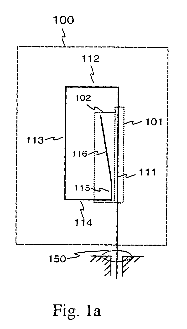
- FIG. 1 is an example of a structure according to a preferred embodiment of the invention which provides an antenna with two operating bands, which are relatively far from each other.
- the structure includes an antenna conductor 100 which seen from the feeder 150 first extends upwards (111), then sidewards (112), further downwards (113) and then sidewards (114) towards the section 111. Let's call the conductor formed by these sections the basic conductor.
- the basic conductor has an extension directed upwards and containing a vertical section 115 and a bent oblique section 116.
- the basic conductor and its extension together form the antenna conductor.
- the antenna does not necessarily require anything else than the conductor shown in the figure, for instance no dielectric matter nor any separate support element.
- Figure 1b shows a structure which in other respects is similar to that of figure la, except that the vertical section 111 is replaced by a vertical section 121, a horizontal section 122 and a vertical section 123.
- the length of the added horizontal section 122 is of the same order as the other horizontal sections.
- a "vertical section” means a substantially vertical part of a conductor and a “horizontal section” means a substantially horizontal part of a conductor, when the antenna points upwards.
- An “oblique section” means a part of a conductor having a direction which differs from both the directions of a vertical section and a horizontal section. Thus the terms “vertical section”, “horizontal section” and “oblique section” are in no way connected to the operating position of the device.
- the structure of figure la has a first resonance frequency, the magnitude of which depends on the total length of the antenna conductor. Between the sections 115 and 116 and the vertical sections 111 there is an electromagnetic coupling causing a second resonance frequency which in this case is substantially above the lower, i.e. the first resonance frequency. The value of the higher, i.e. the second resonance frequency depends mainly on the lengths of the vertical sections.
- the first band means that frequency range around the first resonance frequency where the antenna is able to radiate substantially.
- the second band means that frequency range around the second resonance frequency where the antenna is able to radiate substantially.
- the width of the first band depends on the ratio of the lengths of the horizontal sections 112 and 114 and on the distance between the vertical sections 115 and 111.
- the width of the second band again depends mainly on the mutual relations between the parts of the electromagnetic coupling: the distance between the vertical sections 115 and 111 and the angle between the oblique section 116 and the vertical section 111.
- the vertical section 115 and the oblique section 116 are at a close distance to the vertical section 111.
- “Close distance” means in this description and particularly in the claims such a distance between two sections of the antenna that the coupling between them substantially affects the radiation characteristics of the antenna, however so that said radiation characteristics are at least substantially retained at the first band.
- a close distance can for instance be of the order of ⁇ /100, where ⁇ is the wavelength of the radiation of the antenna.
- the structures according to figure 1 are characterised in that they can provide relatively large bandwidths, particularly a wide upper bandwidth.
- the antenna band characteristics are often examined by measuring its reflection coefficient, i.e. the parameter s 11 or the return loss A r as a function of the frequency.
- the return loss means the ratio of the energy supplied to the antenna to the energy returning from it. It is the inverse of the square of the absolute value of the reflection coefficient. The higher the return loss is, the greater part of the energy supplied into the antenna will radiate into the environment, i.e. the better the antenna functions. In the ideal case the return loss is thus infinite. When the return loss is one or 0 dB the antenna will not radiate at all: the energy supplied into it will return to the feeding source.
- the reception characteristics of the antenna follow the transmission characteristics: the more effectively the antenna transmits at a certain frequency and in a certain direction, the more effectively it also receives said frequency from said direction.
- figure 3 there is an example of the variations of the return loss A r in different operating situations as a function of the frequency for the antenna according to figure 1.
- the operating situations are shown in figure 5.
- the antenna of the mobile station is at the top and pointing upwards, and there are no other objects close to the mobile station.
- figure 5b there is a human head adjacent the mobile station.
- figure 5c there is a multi-function mobile station having its antenna at the top, but in an oblique position, as it could be during use.
- the antenna is turned into a protected position close to the cover of the mobile station.
- the curve 31 represents the situation of figure 5a
- the curve 32 represents the situation of figure 5b
- the curve 33 represents the situation of figure 5c
- the curve 34 represents the situation of figure 5d.
- the antenna is intended to operate on one hand in the band used by the GSM network and on the other hand in the band used by both the PCN and PCS networks.
- the two latter cover the band between 1.71 GHz and 1.98 GHz, wherefore particularly the second band, i.e. the upper band of the antenna must be a wide one. From the curves it is seen that a condition of an acceptable operation is met, except for the curve 34, when a return loss A r value of 5 dB is considered as the limit. In this case, i.e.
- the antenna in the case of a down turned antenna the antenna operates unsatisfactorily at the upper end of the bands used by both the GSM and PCS networks.
- the figures are measurement results obtained in an exemplary test arrangement, and thus they do not represent the performance of a finally optimised product.
- the radiation generated by the antennas according to figure 1 in a common mobile station is mainly vertically polarised; the difference to the horizontally polarised field strength is almost 10 dB on the average.
- the directional pattern regarding the vertically polarised field is relatively even.
- said polarisation difference can not be detected on the basis of a certain measurement arrangement.
- Figure 2a shows an example of a structure where the bandwidth of an one-band antenna 200 is extended according to the invention.
- the basic conductor in this structure forms a rectangular meander pattern.
- the term "meander” means a continuous line without branching points and having a certain basic pattern or a variation of the basic pattern or different basic patterns successively repeated in the same direction.
- a vertical section 202 which has an electromagnetic coupling the to the closest parts 201 of the meander pattern. This results in a further resonance frequency relatively close the main resonance frequency of the basic structure.
- Figure 2b shows a structure which is similar to that of figure 2a, except that the meander pattern is made narrower at the upper part, so that the total width of the antenna is kept constant, taking into consideration the extension, i.e. the vertical section 202.
- Figure 4 is an example of the effect caused by the vertical section 202 on the bandwidth of the antennas according to figure 2.
- the curves 41 and 42 represent the return loss A r as a function of the frequency in an antenna with a meander pattern, which is turned into the protected position according to the figure 5d.
- the curve 41 represents an antenna without the vertical section 202
- the curve 42 represents an antenna according to the invention having a vertical section 202. In the latter case the tail edge of the band is moved about 50 MHz further. The front edge of the band has also moved a little further. A satisfactory operation is achieved in the range used by the GSM network, because the band is widened.
- the curve 43 represents the return loss in free space when the antenna is in a normal operating position. There is only one curve, because the band does not substantially change with the addition according to the invention. The aim in said structure was also to improve the antenna characteristics only in said protective position.
- Figure 6 shows examples of possible applications.
- Figure 6a has a meander structure where an electromagnetic feed-back is made close to the feeding point of the antenna.
- the structure of figure 6b has two coupling points relatively far from each other.
- figure 6c the invention is applied in an L-antenna.
- the inventive idea can be applied in numerous ways within the limits defined by the claims.
Abstract
Description
- The object of the invention is an antenna structure defined in the preamble of claim 1, particularly an antenna structure suitable for mobile stations.
- The progress of mobile station techniques have brought and will bring to the marketplace new and versatile models, in which new requirements are placed on the antennas: for instance, the antenna must operate on two frequency ranges, such as the 900 MHz and 1.8 GHz ranges; the bandwidth or bandwidths must be relatively wide; the radiation and reception characteristics must be rather good when the device and the antenna are in different positions and in different locations regarding external objects; and yet the antenna must be relatively small and compact.
- There are previously known antenna structures suitable for mobile stations which have a wide bandwidth or which operate on two frequency ranges.
- Antennas based on a helix: Within a helix element there is placed a rod element resonating at a different frequency, whereby the rod element is fed separately or in common with the helix element, or it could be a parasitic rod. Disadvantages of such structures are the relatively high manufacturing costs and clearly deteriorated characteristics, when the antenna is located or turned close to the frame of the device.
- Microstrip structures: On the surfaces of and possibly within a dielectric plate there are radiating conductor areas, of which one or more can be a feed area, and of which one or more can be parasitic areas. The conductor areas can also be designed so that they contain one or more gaps acting as radiators. A disadvantage of most microstrip structures are their relatively narrow bandwidths. This disadvantage is less pronounced in structures containing parasitic elements, but then a disadvantage will be the relatively large size of the structure. The characteristics of microstrip antennas are also subject to drift, and the costs of structures fulfilling said requirements are rather high.
- Chip structures: Within a dielectric monolithic body there are one or more conductors, for instance with a meander form, which radiate at different frequencies. A disadvantage of these structures are the relatively narrow bandwidths, if the bands are separate.
- The object of the invention is to reduce the above mentioned disadvantages relating to the prior art. An antenna according to the invention is characterised in what is presented in the independent claim regarding an antenna. A mobile station according to the invention is characterised in what is presented in the independent claim regarding a mobile station. Some preferred embodiments of the invention are presented in the dependent claims.
- The basic idea of the invention is as follows: The basis of the structure is a quarter-wave antenna, which can be electrically shortened with the aid of the design of a radiating conductor. Then the conductor is extended, as seen from the end opposite to the feeding end, so that at least a part of the extended conductor is located rather close to the original antenna structure. In this way an electromagnetic feed-back is created in the antenna. The feed-back provides the antenna with an extra resonance frequency at a desired point on the frequency axis.
- One advantage of the invention is that the antenna can be made into a two-band antenna by arranging the first resonance frequency for instance in the 900 MHz band and the second one for instance in the 1.8 GHz band. The bandwidth can also be made relatively wide in both operating ranges, which is important particularly when the device is used in different positions. An advantage of the invention is further that the bandwidth of an antenna intended for single-band operation can be expanded by arranging a second resonance frequency close to the first one. A wider band also means a better matching in different operating positions of the device. A further advantage is that the antenna can be made very small and flat. On one hand it can then be turned into a protected position near the frame of the device, and on the other hand its electric properties are kept at an acceptable level in the protected position, because the distance to the frame of the device remains relatively large. A further advantage of the invention is that due to the flat form of the antenna it can in mobile phones be fastened to the back wall of the device, whereby the power emitted from the telephone to the user's body is kept as low as possible, which is advantageous due to the power consumption savings in the mobile station. A further advantage of the invention is that the antenna can be rather freely located. because it does not require any particular dielectric medium nor any parasitic elements. Due to the same reason the characteristics of the antenna remain stable over time and in changing environmental conditions. A further advantage of the invention is that the costs of the antenna are relatively low due to the very simple structure.
- The invention is described in detail below. In the description reference is made to the enclosed drawings, in which
- Figure 1 shows an example of antennas according to a preferred embodiment of the invention,
- Figure 2 shows other examples of antennas according to a preferred embodiment of the invention,
- Figure 3 shows characteristics of the band of antennas according to figure 1,
- Figure 4 shows characteristics of the band of antennas according to figure 2,
- Figure 5 shows an antenna according to a preferred embodiment of the invention mounted in a mobile station in different situations, and
- Figure 6 shows some variations of the antenna structure according to the invention.
-
- Figure 1 is an example of a structure according to a preferred embodiment of the invention which provides an antenna with two operating bands, which are relatively far from each other. The structure includes an
antenna conductor 100 which seen from thefeeder 150 first extends upwards (111), then sidewards (112), further downwards (113) and then sidewards (114) towards thesection 111. Let's call the conductor formed by these sections the basic conductor. The basic conductor has an extension directed upwards and containing avertical section 115 and a bentoblique section 116. The basic conductor and its extension together form the antenna conductor. The antenna does not necessarily require anything else than the conductor shown in the figure, for instance no dielectric matter nor any separate support element. Figure 1b shows a structure which in other respects is similar to that of figure la, except that thevertical section 111 is replaced by avertical section 121, ahorizontal section 122 and avertical section 123. The length of the addedhorizontal section 122 is of the same order as the other horizontal sections. In this description and particularly in the claims a "vertical section" means a substantially vertical part of a conductor and a "horizontal section" means a substantially horizontal part of a conductor, when the antenna points upwards. An "oblique section" means a part of a conductor having a direction which differs from both the directions of a vertical section and a horizontal section. Thus the terms "vertical section", "horizontal section" and "oblique section" are in no way connected to the operating position of the device. - The structure of figure la has a first resonance frequency, the magnitude of which depends on the total length of the antenna conductor. Between the
sections vertical sections 111 there is an electromagnetic coupling causing a second resonance frequency which in this case is substantially above the lower, i.e. the first resonance frequency. The value of the higher, i.e. the second resonance frequency depends mainly on the lengths of the vertical sections. The first band means that frequency range around the first resonance frequency where the antenna is able to radiate substantially. Correspondingly, the second band means that frequency range around the second resonance frequency where the antenna is able to radiate substantially. The width of the first band depends on the ratio of the lengths of thehorizontal sections vertical sections vertical sections oblique section 116 and thevertical section 111. Thevertical section 115 and theoblique section 116 are at a close distance to thevertical section 111. "Close distance" means in this description and particularly in the claims such a distance between two sections of the antenna that the coupling between them substantially affects the radiation characteristics of the antenna, however so that said radiation characteristics are at least substantially retained at the first band. A close distance can for instance be of the order of λ/100, where λ is the wavelength of the radiation of the antenna. - The structures according to figure 1 are characterised in that they can provide relatively large bandwidths, particularly a wide upper bandwidth. The antenna band characteristics are often examined by measuring its reflection coefficient, i.e. the parameter s11 or the return loss Ar as a function of the frequency. The return loss means the ratio of the energy supplied to the antenna to the energy returning from it. It is the inverse of the square of the absolute value of the reflection coefficient. The higher the return loss is, the greater part of the energy supplied into the antenna will radiate into the environment, i.e. the better the antenna functions. In the ideal case the return loss is thus infinite. When the return loss is one or 0 dB the antenna will not radiate at all: the energy supplied into it will return to the feeding source. The reception characteristics of the antenna follow the transmission characteristics: the more effectively the antenna transmits at a certain frequency and in a certain direction, the more effectively it also receives said frequency from said direction. The bandwidth of an antenna can be defined in different ways: It can mean the difference between those frequencies at which the return loss has decreased 3 dB from the best value, i.e. from the maximum value. However, often the bandwidth is regarded as the difference between those frequencies at which the return loss obtains a certain value, for
instance 10 dB = 10, or 5 dB ≈ 3.2. The former value corresponds to a standing wave ratio SWR = 1.9 which represents the quality of the antenna matching, and the latter value represents a value SWR = 3.6. In figure 3 there is an example of the variations of the return loss Ar in different operating situations as a function of the frequency for the antenna according to figure 1. The operating situations are shown in figure 5. In figure 5a the antenna of the mobile station is at the top and pointing upwards, and there are no other objects close to the mobile station. In figure 5b there is a human head adjacent the mobile station. In figure 5c there is a multi-function mobile station having its antenna at the top, but in an oblique position, as it could be during use. In figure 5d the antenna is turned into a protected position close to the cover of the mobile station. Thecurve 31 represents the situation of figure 5a, thecurve 32 represents the situation of figure 5b, thecurve 33 represents the situation of figure 5c, and thecurve 34 represents the situation of figure 5d. In this example the antenna is intended to operate on one hand in the band used by the GSM network and on the other hand in the band used by both the PCN and PCS networks. The two latter cover the band between 1.71 GHz and 1.98 GHz, wherefore particularly the second band, i.e. the upper band of the antenna must be a wide one. From the curves it is seen that a condition of an acceptable operation is met, except for thecurve 34, when a return loss Ar value of 5 dB is considered as the limit. In this case, i.e. in the case of a down turned antenna the antenna operates unsatisfactorily at the upper end of the bands used by both the GSM and PCS networks. The figures are measurement results obtained in an exemplary test arrangement, and thus they do not represent the performance of a finally optimised product. - When the mobile station is in a vertical position the radiation generated by the antennas according to figure 1 in a common mobile station is mainly vertically polarised; the difference to the horizontally polarised field strength is almost 10 dB on the average. The directional pattern regarding the vertically polarised field is relatively even. When mounted in a certain multi-function mobile station said polarisation difference can not be detected on the basis of a certain measurement arrangement.
- Figure 2a shows an example of a structure where the bandwidth of an one-
band antenna 200 is extended according to the invention. The basic conductor in this structure forms a rectangular meander pattern. The term "meander" means a continuous line without branching points and having a certain basic pattern or a variation of the basic pattern or different basic patterns successively repeated in the same direction. As an extension of the meander pattern there is adjacent one side of it avertical section 202, which has an electromagnetic coupling the to theclosest parts 201 of the meander pattern. This results in a further resonance frequency relatively close the main resonance frequency of the basic structure. Figure 2b shows a structure which is similar to that of figure 2a, except that the meander pattern is made narrower at the upper part, so that the total width of the antenna is kept constant, taking into consideration the extension, i.e. thevertical section 202. - Figure 4 is an example of the effect caused by the
vertical section 202 on the bandwidth of the antennas according to figure 2. Thecurves 41 and 42 represent the return loss Ar as a function of the frequency in an antenna with a meander pattern, which is turned into the protected position according to the figure 5d. The curve 41 represents an antenna without thevertical section 202, and thecurve 42 represents an antenna according to the invention having avertical section 202. In the latter case the tail edge of the band is moved about 50 MHz further. The front edge of the band has also moved a little further. A satisfactory operation is achieved in the range used by the GSM network, because the band is widened. Thecurve 43 represents the return loss in free space when the antenna is in a normal operating position. There is only one curve, because the band does not substantially change with the addition according to the invention. The aim in said structure was also to improve the antenna characteristics only in said protective position. - Some antenna structures according to the invention and their characteristics were described above. The invention is not limited to the above described solutions. Figure 6 shows examples of possible applications. Figure 6a has a meander structure where an electromagnetic feed-back is made close to the feeding point of the antenna. The structure of figure 6b has two coupling points relatively far from each other. In figure 6c the invention is applied in an L-antenna. The inventive idea can be applied in numerous ways within the limits defined by the claims.
Claims (7)
- An antenna (100, 200) comprising a conductor which has a first end and a second end, whereby said first end is arranged to be connected to the antenna feeding conductor (150) and whereby said second end is the open end of the antenna, characterised in thatthe conductor forms a substantially planar pattern,said second end is closer to said first end than a point of the first conductor between said first and second ends, andsaid second end is closer to a second conductor point than to said first end, whereby said second conductor point is located, when measured along the conductor, between said first conductor point and said first end.
- An antenna (100) according to claim 1, characterised in that said conductor forms a pattern which comprises the following sections in this order starting from said first end:a first section (111) in a first direction,a second section (112) in a second direction, whereby said second direction is approximately perpendicular to said first direction,a third section (113) in a third direction, whereby said third direction is approximately opposite to said first direction,a fourth section (114) in a fourth direction, whereby said fourth direction is approximately opposite to said second direction,a fifth section (115) approximately in said first direction, anda sixth section (116), whereby said sixth section is directed in a direction which substantially differs from the directions mentioned above in this claim, and that said second section (112) and said fourth section (114) both are shorter than said first section (111) and said third section (113).
- An antenna (100) according to claim 1, characterised in that said conductor forms a pattern which comprises the following sections in this order starting from said first end:a first section (121) in a first direction,a second section (122) in a second direction, whereby said second direction is approximately perpendicular to said first direction,a third section (123) approximately in the first direction,a fourth section (124) in a third direction, whereby said third direction is approximately opposite to said second direction,a fifth section (125) in a fourth direction, whereby said fourth direction is approximately opposite to said first direction,a sixth section (126) approximately in said second direction,a seventh section (127) approximately in said first direction, andan eighth section (128), whereby said eighth section is directed in a direction which substantially differs from the directions mentioned above in this claim, and that said second section (122), said fourth section (124) and said sixth section (126) all are shorter than said third section (123) and said fifth section (125).
- An antenna (200) according to claim 1, characterised in that said conductor forms a pattern which comprises the following sections in this order starting from said first end:a section of the meander type in a first direction,a straight section (202) in a second direction, whereby said second direction is approximately opposite to said first direction.
- An antenna according claim 1, characterised in that said conductor is self-supporting.
- A mobile station (51; 52) having an antenna, which has a conductor which has a first end and a second end, whereby said first end is arranged to be connected to the antenna feeding conductor (150) and whereby said second end is the open end of the antenna, characterised in thatthe conductor forms a substantially planar pattern,said second end is closer to said first end than a point of the first conductor between said first and second ends, andsaid second end is closer to a second conductor point than to said first end, whereby said second conductor point is located, when measured along the conductor, between said first conductor point and said first end.
- A mobile station according to claim 6, characterised in that said antenna is located inside a wall of the cover of a mobile station.
Applications Claiming Priority (3)
| Application Number | Priority Date | Filing Date | Title |
|---|---|---|---|
| FI980392A FI980392A (en) | 1998-02-20 | 1998-02-20 | Antenna |
| FI980392 | 1998-02-20 | ||
| US09/252,159 US6111545A (en) | 1992-01-23 | 1999-02-18 | Antenna |
Publications (2)
| Publication Number | Publication Date |
|---|---|
| EP0938158A2 true EP0938158A2 (en) | 1999-08-25 |
| EP0938158A3 EP0938158A3 (en) | 2000-11-02 |
Family
ID=26160546
Family Applications (1)
| Application Number | Title | Priority Date | Filing Date |
|---|---|---|---|
| EP99660027A Withdrawn EP0938158A3 (en) | 1998-02-20 | 1999-02-17 | Antenna |
Country Status (2)
| Country | Link |
|---|---|
| EP (1) | EP0938158A3 (en) |
| FI (1) | FI980392A (en) |
Cited By (15)
| Publication number | Priority date | Publication date | Assignee | Title |
|---|---|---|---|---|
| WO2001099228A1 (en) * | 2000-06-22 | 2001-12-27 | Telefonaktiebolaget Lm Ericsson (Publ) | An antenna for a portable communication apparatus, and a portable communication apparatus comprising such an antenna |
| US6950072B2 (en) | 2002-10-23 | 2005-09-27 | Murata Manufacturing Co., Ltd. | Surface mount antenna, antenna device using the same, and communication device |
| EP1579529A2 (en) * | 2002-12-17 | 2005-09-28 | Ethertronics, Inc. | Antennas with reduced space and improved performance |
| JP2006510321A (en) * | 2002-12-22 | 2006-03-23 | フラクタス・ソシエダッド・アノニマ | Multiband monopole antenna for mobile communication devices |
| WO2006073034A1 (en) * | 2005-01-05 | 2006-07-13 | Murata Manufacturing Co., Ltd. | Antenna structure and wireless communication unit having the same |
| EP1764866A1 (en) * | 2005-09-15 | 2007-03-21 | Infineon Tehnologies AG | Miniaturized integrated monopole antenna |
| WO2007045665A1 (en) * | 2005-10-18 | 2007-04-26 | Palm, Inc. | Multiple resonant antenna unit, printed circuit board belonging thereto, and radio communications unit |
| US7239889B2 (en) | 2001-10-31 | 2007-07-03 | Nokia Corporation | Antenna system for GSM/WLAN radio operation |
| DE10226910B4 (en) * | 2001-06-20 | 2007-07-05 | Murata Manufacturing Co. Ltd. | Surface mount antenna and use thereof |
| US7423592B2 (en) | 2004-01-30 | 2008-09-09 | Fractus, S.A. | Multi-band monopole antennas for mobile communications devices |
| US8207893B2 (en) | 2000-01-19 | 2012-06-26 | Fractus, S.A. | Space-filling miniature antennas |
| US9099773B2 (en) | 2006-07-18 | 2015-08-04 | Fractus, S.A. | Multiple-body-configuration multimedia and smartphone multifunction wireless devices |
| DE102005047418B4 (en) * | 2004-10-14 | 2016-07-07 | Mediatek Inc. | Multi-band antenna device, wireless data transmission device and radio frequency chip |
| US9755314B2 (en) | 2001-10-16 | 2017-09-05 | Fractus S.A. | Loaded antenna |
| US9761934B2 (en) | 1999-09-20 | 2017-09-12 | Fractus, S.A. | Multilevel antennae |
Citations (6)
| Publication number | Priority date | Publication date | Assignee | Title |
|---|---|---|---|---|
| US2647211A (en) * | 1949-01-11 | 1953-07-28 | Lynne C Smeby | Radio antenna |
| JPH057109A (en) * | 1991-06-27 | 1993-01-14 | Mitsubishi Electric Corp | Built-in antenna for portable telephone set |
| US5289198A (en) * | 1992-08-21 | 1994-02-22 | The United States Of America As Represented By The Secretary Of The Air Force | Double-folded monopole |
| US5363114A (en) * | 1990-01-29 | 1994-11-08 | Shoemaker Kevin O | Planar serpentine antennas |
| US5526007A (en) * | 1992-03-26 | 1996-06-11 | Aisin Seiki Kabushiki Kaisha | Wire antenna for circularly polarized wave |
| EP0814536A2 (en) * | 1996-06-20 | 1997-12-29 | Kabushiki Kaisha Yokowo | Antenna and radio apparatus using same |
-
1998
- 1998-02-20 FI FI980392A patent/FI980392A/en unknown
-
1999
- 1999-02-17 EP EP99660027A patent/EP0938158A3/en not_active Withdrawn
Patent Citations (6)
| Publication number | Priority date | Publication date | Assignee | Title |
|---|---|---|---|---|
| US2647211A (en) * | 1949-01-11 | 1953-07-28 | Lynne C Smeby | Radio antenna |
| US5363114A (en) * | 1990-01-29 | 1994-11-08 | Shoemaker Kevin O | Planar serpentine antennas |
| JPH057109A (en) * | 1991-06-27 | 1993-01-14 | Mitsubishi Electric Corp | Built-in antenna for portable telephone set |
| US5526007A (en) * | 1992-03-26 | 1996-06-11 | Aisin Seiki Kabushiki Kaisha | Wire antenna for circularly polarized wave |
| US5289198A (en) * | 1992-08-21 | 1994-02-22 | The United States Of America As Represented By The Secretary Of The Air Force | Double-folded monopole |
| EP0814536A2 (en) * | 1996-06-20 | 1997-12-29 | Kabushiki Kaisha Yokowo | Antenna and radio apparatus using same |
Non-Patent Citations (2)
| Title |
|---|
| PATENT ABSTRACTS OF JAPAN vol. 017, no. 264 (E-1370), 24 May 1993 (1993-05-24) -& JP 05 007109 A (MITSUBISHI ELECTRIC CORP), 14 January 1993 (1993-01-14) * |
| ROEDERER A G: "THE CROSS ANTENNA: A NEW LOW-PROFILE CIRCULARLY POLARIZED RADIATOR" IEEE TRANSACTIONS ON ANTENNAS AND PROPAGATION,US,IEEE INC. NEW YORK, vol. 38, no. 5, 1 May 1990 (1990-05-01), pages 704-710, XP000135617 ISSN: 0018-926X * |
Cited By (38)
| Publication number | Priority date | Publication date | Assignee | Title |
|---|---|---|---|---|
| US10056682B2 (en) | 1999-09-20 | 2018-08-21 | Fractus, S.A. | Multilevel antennae |
| US9761934B2 (en) | 1999-09-20 | 2017-09-12 | Fractus, S.A. | Multilevel antennae |
| US8207893B2 (en) | 2000-01-19 | 2012-06-26 | Fractus, S.A. | Space-filling miniature antennas |
| US10355346B2 (en) | 2000-01-19 | 2019-07-16 | Fractus, S.A. | Space-filling miniature antennas |
| US8610627B2 (en) | 2000-01-19 | 2013-12-17 | Fractus, S.A. | Space-filling miniature antennas |
| US8558741B2 (en) | 2000-01-19 | 2013-10-15 | Fractus, S.A. | Space-filling miniature antennas |
| US8471772B2 (en) | 2000-01-19 | 2013-06-25 | Fractus, S.A. | Space-filling miniature antennas |
| US8212726B2 (en) | 2000-01-19 | 2012-07-03 | Fractus, Sa | Space-filling miniature antennas |
| US7053839B2 (en) | 2000-06-22 | 2006-05-30 | Telefonaktiebolaget L M Ericsson (Publ) | Antenna for a portable communication apparatus, and a portable communication apparatus comprising such an antenna |
| WO2001099228A1 (en) * | 2000-06-22 | 2001-12-27 | Telefonaktiebolaget Lm Ericsson (Publ) | An antenna for a portable communication apparatus, and a portable communication apparatus comprising such an antenna |
| DE10226910B4 (en) * | 2001-06-20 | 2007-07-05 | Murata Manufacturing Co. Ltd. | Surface mount antenna and use thereof |
| US9755314B2 (en) | 2001-10-16 | 2017-09-05 | Fractus S.A. | Loaded antenna |
| US7239889B2 (en) | 2001-10-31 | 2007-07-03 | Nokia Corporation | Antenna system for GSM/WLAN radio operation |
| US6950072B2 (en) | 2002-10-23 | 2005-09-27 | Murata Manufacturing Co., Ltd. | Surface mount antenna, antenna device using the same, and communication device |
| EP1579529A4 (en) * | 2002-12-17 | 2007-09-19 | Ethertronics Inc | Antennas with reduced space and improved performance |
| EP1579529A2 (en) * | 2002-12-17 | 2005-09-28 | Ethertronics, Inc. | Antennas with reduced space and improved performance |
| US8674887B2 (en) | 2002-12-22 | 2014-03-18 | Fractus, S.A. | Multi-band monopole antenna for a mobile communications device |
| US7411556B2 (en) | 2002-12-22 | 2008-08-12 | Fractus, S.A. | Multi-band monopole antenna for a mobile communications device |
| US8253633B2 (en) | 2002-12-22 | 2012-08-28 | Fractus, S.A. | Multi-band monopole antenna for a mobile communications device |
| US8259016B2 (en) | 2002-12-22 | 2012-09-04 | Fractus, S.A. | Multi-band monopole antenna for a mobile communications device |
| US8456365B2 (en) | 2002-12-22 | 2013-06-04 | Fractus, S.A. | Multi-band monopole antennas for mobile communications devices |
| US7403164B2 (en) | 2002-12-22 | 2008-07-22 | Fractus, S.A. | Multi-band monopole antenna for a mobile communications device |
| JP2006510321A (en) * | 2002-12-22 | 2006-03-23 | フラクタス・ソシエダッド・アノニマ | Multiband monopole antenna for mobile communication devices |
| US7675470B2 (en) | 2002-12-22 | 2010-03-09 | Fractus, S.A. | Multi-band monopole antenna for a mobile communications device |
| US7423592B2 (en) | 2004-01-30 | 2008-09-09 | Fractus, S.A. | Multi-band monopole antennas for mobile communications devices |
| DE102005047418B4 (en) * | 2004-10-14 | 2016-07-07 | Mediatek Inc. | Multi-band antenna device, wireless data transmission device and radio frequency chip |
| WO2006073034A1 (en) * | 2005-01-05 | 2006-07-13 | Murata Manufacturing Co., Ltd. | Antenna structure and wireless communication unit having the same |
| US7538732B2 (en) | 2005-01-05 | 2009-05-26 | Murata Manufacturing Co., Ltd. | Antenna structure and radio communication apparatus including the same |
| US7675463B2 (en) | 2005-09-15 | 2010-03-09 | Infineon Technologies Ag | Miniaturized integrated monopole antenna |
| EP1764866A1 (en) * | 2005-09-15 | 2007-03-21 | Infineon Tehnologies AG | Miniaturized integrated monopole antenna |
| WO2007045665A1 (en) * | 2005-10-18 | 2007-04-26 | Palm, Inc. | Multiple resonant antenna unit, printed circuit board belonging thereto, and radio communications unit |
| US8816911B2 (en) | 2005-10-18 | 2014-08-26 | Qualcomm Incorporated | Multiple resonant antenna unit, associated printed circuit board and radio communication |
| US11735810B2 (en) | 2006-07-18 | 2023-08-22 | Fractus, S.A. | Multiple-body-configuration multimedia and smartphone multifunction wireless devices |
| US9899727B2 (en) | 2006-07-18 | 2018-02-20 | Fractus, S.A. | Multiple-body-configuration multimedia and smartphone multifunction wireless devices |
| US9099773B2 (en) | 2006-07-18 | 2015-08-04 | Fractus, S.A. | Multiple-body-configuration multimedia and smartphone multifunction wireless devices |
| US10644380B2 (en) | 2006-07-18 | 2020-05-05 | Fractus, S.A. | Multiple-body-configuration multimedia and smartphone multifunction wireless devices |
| US11031677B2 (en) | 2006-07-18 | 2021-06-08 | Fractus, S.A. | Multiple-body-configuration multimedia and smartphone multifunction wireless devices |
| US11349200B2 (en) | 2006-07-18 | 2022-05-31 | Fractus, S.A. | Multiple-body-configuration multimedia and smartphone multifunction wireless devices |
Also Published As
| Publication number | Publication date |
|---|---|
| EP0938158A3 (en) | 2000-11-02 |
| FI980392A0 (en) | 1998-02-20 |
| FI980392A (en) | 1999-08-21 |
Similar Documents
| Publication | Publication Date | Title |
|---|---|---|
| US6111545A (en) | Antenna | |
| US10734723B2 (en) | Couple multiband antennas | |
| KR100665007B1 (en) | Ultra wide band internal antenna | |
| US6498586B2 (en) | Method for coupling a signal and an antenna structure | |
| US7034754B2 (en) | Multi-band antenna | |
| KR100981883B1 (en) | Internal Wide Band Antenna Using Slow Wave Structure | |
| US6326927B1 (en) | Capacitively-tuned broadband antenna structure | |
| US7804458B2 (en) | Slot antenna | |
| US20090040110A1 (en) | Multi-band planar inverted-f antenna | |
| US9755314B2 (en) | Loaded antenna | |
| CA2529796C (en) | Internal antenna with slots | |
| EP0938158A2 (en) | Antenna | |
| KR100638661B1 (en) | Ultra wide band internal antenna | |
| US20030103015A1 (en) | Skeleton slot radiation element and multi-band patch antenna using the same | |
| US7365689B2 (en) | Metal inverted F antenna | |
| JP4431360B2 (en) | Multiband antenna | |
| Liao et al. | Miniaturized PIFA antenna for 2.4 GHz ISM band applications | |
| KR20070043274A (en) | Impedance transformation type wide band antenna | |
| JPH05299929A (en) | Antenna | |
| AbuTarboush et al. | Design of planar inverted-F antennas (PIFA) for multiband wireless applications | |
| Pandey et al. | Defected star-shaped microstrip patch antenna for broadband applications | |
| EP1253667A1 (en) | Patch antenna | |
| US10903551B2 (en) | Antenna device | |
| US7474266B2 (en) | Metal inverted F antenna | |
| Calhau et al. | Low profile multi-band antenna for mobile communications |
Legal Events
| Date | Code | Title | Description |
|---|---|---|---|
| PUAI | Public reference made under article 153(3) epc to a published international application that has entered the european phase |
Free format text: ORIGINAL CODE: 0009012 |
|
| AK | Designated contracting states |
Kind code of ref document: A2 Designated state(s): DE FR GB NL |
|
| AX | Request for extension of the european patent |
Free format text: AL;LT;LV;MK;RO;SI |
|
| PUAL | Search report despatched |
Free format text: ORIGINAL CODE: 0009013 |
|
| RIC1 | Information provided on ipc code assigned before grant |
Free format text: 7H 01Q 9/42 A, 7H 01Q 5/00 B, 7H 01Q 1/36 B, 7H 01Q 1/24 B, 7H 01Q 11/04 B, 7H 01Q 11/14 B |
|
| AK | Designated contracting states |
Kind code of ref document: A3 Designated state(s): AT BE CH CY DE DK ES FI FR GB GR IE IT LI LU MC NL PT SE |
|
| AX | Request for extension of the european patent |
Free format text: AL;LT;LV;MK;RO;SI |
|
| 17P | Request for examination filed |
Effective date: 20010326 |
|
| AKX | Designation fees paid |
Free format text: DE FR GB NL |
|
| RAP1 | Party data changed (applicant data changed or rights of an application transferred) |
Owner name: NOKIA CORPORATION |
|
| 17Q | First examination report despatched |
Effective date: 20021113 |
|
| STAA | Information on the status of an ep patent application or granted ep patent |
Free format text: STATUS: THE APPLICATION IS DEEMED TO BE WITHDRAWN |
|
| 18D | Application deemed to be withdrawn |
Effective date: 20030325 |