EP0937687B1 - Method and apparatus for the localization of heating in a tempering furnace for glass panels - Google Patents
Method and apparatus for the localization of heating in a tempering furnace for glass panels Download PDFInfo
- Publication number
- EP0937687B1 EP0937687B1 EP99660015A EP99660015A EP0937687B1 EP 0937687 B1 EP0937687 B1 EP 0937687B1 EP 99660015 A EP99660015 A EP 99660015A EP 99660015 A EP99660015 A EP 99660015A EP 0937687 B1 EP0937687 B1 EP 0937687B1
- Authority
- EP
- European Patent Office
- Prior art keywords
- furnace
- glass panels
- heating
- resistances
- set forth
- Prior art date
- Legal status (The legal status is an assumption and is not a legal conclusion. Google has not performed a legal analysis and makes no representation as to the accuracy of the status listed.)
- Expired - Lifetime
Links
- 239000011521 glass Substances 0.000 title claims description 41
- 238000010438 heat treatment Methods 0.000 title claims description 40
- 238000000034 method Methods 0.000 title claims description 10
- 230000004807 localization Effects 0.000 title claims description 6
- 238000005496 tempering Methods 0.000 title claims description 6
- 230000005855 radiation Effects 0.000 claims description 13
- 238000005422 blasting Methods 0.000 claims description 3
- 230000000052 comparative effect Effects 0.000 claims 1
- 238000009826 distribution Methods 0.000 description 2
- 238000012800 visualization Methods 0.000 description 2
- 239000012141 concentrate Substances 0.000 description 1
- 230000001419 dependent effect Effects 0.000 description 1
- 230000005670 electromagnetic radiation Effects 0.000 description 1
- 239000011159 matrix material Substances 0.000 description 1
- 230000000153 supplemental effect Effects 0.000 description 1
- 238000009827 uniform distribution Methods 0.000 description 1
Images


Classifications
-
- C—CHEMISTRY; METALLURGY
- C03—GLASS; MINERAL OR SLAG WOOL
- C03B—MANUFACTURE, SHAPING, OR SUPPLEMENTARY PROCESSES
- C03B27/00—Tempering or quenching glass products
- C03B27/04—Tempering or quenching glass products using gas
- C03B27/044—Tempering or quenching glass products using gas for flat or bent glass sheets being in a horizontal position
-
- C—CHEMISTRY; METALLURGY
- C03—GLASS; MINERAL OR SLAG WOOL
- C03B—MANUFACTURE, SHAPING, OR SUPPLEMENTARY PROCESSES
- C03B27/00—Tempering or quenching glass products
- C03B27/012—Tempering or quenching glass products by heat treatment, e.g. for crystallisation; Heat treatment of glass products before tempering by cooling
-
- C—CHEMISTRY; METALLURGY
- C03—GLASS; MINERAL OR SLAG WOOL
- C03B—MANUFACTURE, SHAPING, OR SUPPLEMENTARY PROCESSES
- C03B27/00—Tempering or quenching glass products
- C03B27/04—Tempering or quenching glass products using gas
- C03B27/0417—Controlling or regulating for flat or bent glass sheets
-
- C—CHEMISTRY; METALLURGY
- C03—GLASS; MINERAL OR SLAG WOOL
- C03B—MANUFACTURE, SHAPING, OR SUPPLEMENTARY PROCESSES
- C03B29/00—Reheating glass products for softening or fusing their surfaces; Fire-polishing; Fusing of margins
- C03B29/04—Reheating glass products for softening or fusing their surfaces; Fire-polishing; Fusing of margins in a continuous way
- C03B29/06—Reheating glass products for softening or fusing their surfaces; Fire-polishing; Fusing of margins in a continuous way with horizontal displacement of the products
- C03B29/08—Glass sheets
Definitions
- the present invention relates to a method for the localization of heating in a tempering furnace for glass panels, wherein the glass panels are carried and supported by rollers and heated to a desired tempering temperature with hot convection air blasted to the opposite surfaces of the glass panels.
- the invention relates also to an apparatus for the localization of heating in a tempering furnace for glass panels, which is provided with rollers for carrying the glass panels, nozzle boxes with nozzles for blasting hot convection air to the opposite surfaces of a glass panel, blowers in a flow communication with the nozzle boxes, intake ports within the furnace in a flow communication with the blowers, and heating resistances for heating the air circulated by the blowers.
- An object of the invention is to provide a method and apparatus of the above type, capable of controlling more effectively than before the temperature distribution over various areas of a load of glass panels or individual glass panels to be heated in a convection furnace.
- the description deals first with an apparatus for implementing the method.
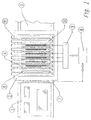
- the apparatus shown in fig. 1 includes a loading table 1, a convection heating furnace 2, and a chilling station 3. As depicted in more detail in figs. 2 and 3, the furnace 2 is provided with nozzle boxes 4 above and nozzle boxes 14 below conveyor rollers 11.
- the blast of hot convection air for heating a glass panel is effected from nozzle heads 5, 15 associated with the nozzle boxes 4, 14, the nozzles present therein comprising e.g. slit nozzles, jet orifices or jet pipes.
- the convection air circulation is effected by means of blowers 6, which are in a flow communication with intake ports 16 opening into the furnace. Between the blowers 6 and the intake ports 16 are resistances 17 for heating the air to be circulated.
- Fig. 3 illustrates an overhead air circulation system, and a respective circulation system is constructed below the array of rollers 11.
- the nozzle boxes 4, 14 are parallel to the rollers 11 and the nozzle heads 5, 15 concentrate a blast between the rollers 11.
- the furnace is provided, between the upper nozzle heads 5, with resistances 10 which are spaced in a lateral direction of the furnace as discrete resistances 10a, 10b, 10c, which are selectively switchable on and off, whereby the extra heating can be performed either by means of the middle resistances 10b or with either one of the side resistances 10a, 10c or with a combination of the middle resistance 10b and either one of the side resistances 10a, 10c.
- the resistances arranged successively lengthwise of the furnace it is possible to switch on one or more resistances anywhere along the length of the furnace.
- the resistances 10a have their own power cables 12a
- the resistances 10b have their own power cables 12b
- the resistances 10c have their own power cables 12c.
- the cable system 12 is extended through a heat-insulated furnace roof 13 and connected to current distribution rails present within housings 18. These are in turn connected to a unit 9, fitted with controlled current switches which are operated by means of a computer-aided control system 8.
- the control system 8 receives the control-required information from scanning or detecting means 7, located in the loading station 1 or between the loading station 1 and the furnace 2.
- the scanning and detecting means 7 can be based e.g. on the back-reflection of electromagnetic radiation or sound waves from glass.
- the means 7 may also comprise CCD-cameras or video cameras.
- the scanning or detecting means 7 are used for reading the load picture of glass panels, i.e. the dimensions and positions of individual glass panels. It is also possible to use glass-contact scanning, e.g. by means of yielding rollers, or scanning carried out by means of small air jets, in which case the jets, when in line with the glass panels, do not transmit the plane of passage of the glass panels.
- the read load picture is stored in the memory of the control system 8 and compared with predetermined parameters. The comparison results in the identification of critical glass panels, and the resistances 10 are used for focusing radiation heating on the central areas of the critical glass panels for providing extra heating therefor.
- the control system 8 may also include a load picture monitor, displaying at the same time a matrix for a multi-zone radiation heating system and resistances activated for heating at any given time.
- a display of this type it is possible to teach the system to choose automatically a given resistance heating picture for a given load picture, such that the extra heating is always focused on the central areas of critical glass panels.
- the control system 8 includes a program which makes use of preset parameter data to determine the degree of extra heating required for a given glass panel in terms of its thickness, width and length. This requirement for extra heating may still vary according to whether the glass panel is positioned in the mid-section or side section of a furnace.
- a decision in terms of resistances to be selectively activated is made automatically on the basis of the program and parameter data used thereby. It is possible to vary such parameter data manually on the basis of operating experiences.
- the heating resistances 10 may comprise a wound single-wire electrical resistance or double-coated direct resistances (e.g. Thermociax from Philips).
- the radiation heating elements must be quick in terms of the action time thereof. In addition to overhead radiation heaters, it is possible to employ lower radiation heaters underneath the rollers 11.
- the heating resistances 10 have an outer diameter and their positioning between the nozzle heads is such that the pressure loss of circulation air will be increased as little as possible thereby. In order to achieve this, it is preferred that the distance between the heating resistances 10 and the external side surfaces of the nozzle heads 5 be greater than or equal to a half of the minimum distance between the nozzle boxes 4.
- the resistances 10a, 10b, 10c are only adapted to extend beyond the mid-section of the furnace by about 2/3 of the width of the furnace, providing the edges of the furnace with zones not occupied by resistances.
- the resistances 10 may cover the entire length of a furnace between all nozzle boxes 4 or just part of the length of a furnace between just a few nozzle boxes.
- the invention is not limited to the use of automated visualization system of the load pattern.
- the operator may manually select (by push buttons) one of different radiation heat localization programs after having visually assessed the load pattern or dimensions of a glass panel. For instance, if large glass panels of predetermined width are loaded, the operator selects a push button, which is indicated to be used by large glass panels having their width within a predetermined range.
Landscapes
- Chemical & Material Sciences (AREA)
- Engineering & Computer Science (AREA)
- Materials Engineering (AREA)
- Organic Chemistry (AREA)
- Physics & Mathematics (AREA)
- Thermal Sciences (AREA)
- Re-Forming, After-Treatment, Cutting And Transporting Of Glass Products (AREA)
- Tunnel Furnaces (AREA)
Description
- The present invention relates to a method for the localization of heating in a tempering furnace for glass panels, wherein the glass panels are carried and supported by rollers and heated to a desired tempering temperature with hot convection air blasted to the opposite surfaces of the glass panels.
- The invention relates also to an apparatus for the localization of heating in a tempering furnace for glass panels, which is provided with rollers for carrying the glass panels, nozzle boxes with nozzles for blasting hot convection air to the opposite surfaces of a glass panel, blowers in a flow communication with the nozzle boxes, intake ports within the furnace in a flow communication with the blowers, and heating resistances for heating the air circulated by the blowers.
- This type of method and apparatus is disclosed in the European patent application EP-A1-649821. The heating of glass panels with a convection air blast involves certain problems in terms of providing the glass panels with a uniform distribution of heat over the entire surface area. In particular, the border areas of critical glass panels tend to heat more than the central areas.
- An object of the invention is to provide a method and apparatus of the above type, capable of controlling more effectively than before the temperature distribution over various areas of a load of glass panels or individual glass panels to be heated in a convection furnace.
- This object is achieved by means of a method as set forth in the annexed
claim 1 and by means of an apparatus as set forth inclaim 4. The dependent claims disclose preferred embodiments of the invention. - One exemplary embodiment of the invention will now be described in more detail with reference made to the accompanying drawings, in which
- fig. 1
- shows in a schematic plan view an apparatus for implementing a method of the invention;
- fig. 2
- shows in a vertical section a convection heating furnace included in an apparatus of the invention, provided with an arrangement of the invention for localized extra heating;
- fig. 2A
- shows a detail of fig. 2 in a larger scale; and
- fig. 3
- shows a top section of the furnace of fig. 2 in a cross-section.
- The description deals first with an apparatus for implementing the method. The apparatus shown in fig. 1 includes a loading table 1, a
convection heating furnace 2, and achilling station 3. As depicted in more detail in figs. 2 and 3, thefurnace 2 is provided withnozzle boxes 4 above andnozzle boxes 14 belowconveyor rollers 11. The blast of hot convection air for heating a glass panel is effected fromnozzle heads nozzle boxes blowers 6, which are in a flow communication withintake ports 16 opening into the furnace. Between theblowers 6 and theintake ports 16 areresistances 17 for heating the air to be circulated. Fig. 3 illustrates an overhead air circulation system, and a respective circulation system is constructed below the array ofrollers 11. - The
nozzle boxes rollers 11 and thenozzle heads rollers 11. - For the purposes of localized extra heating, the furnace is provided, between the
upper nozzle heads 5, withresistances 10 which are spaced in a lateral direction of the furnace asdiscrete resistances middle resistances 10b or with either one of theside resistances 10a, 10c or with a combination of themiddle resistance 10b and either one of theside resistances 10a, 10c. As for the resistances arranged successively lengthwise of the furnace, it is possible to switch on one or more resistances anywhere along the length of the furnace. - The resistances 10a have their own power cables 12a, the
resistances 10b have theirown power cables 12b, and theresistances 10c have theirown power cables 12c. Thecable system 12 is extended through a heat-insulatedfurnace roof 13 and connected to current distribution rails present withinhousings 18. These are in turn connected to a unit 9, fitted with controlled current switches which are operated by means of a computer-aidedcontrol system 8. On the other hand, thecontrol system 8 receives the control-required information from scanning or detecting means 7, located in theloading station 1 or between theloading station 1 and thefurnace 2. The scanning and detecting means 7 can be based e.g. on the back-reflection of electromagnetic radiation or sound waves from glass. Themeans 7 may also comprise CCD-cameras or video cameras. The scanning or detecting means 7 are used for reading the load picture of glass panels, i.e. the dimensions and positions of individual glass panels. It is also possible to use glass-contact scanning, e.g. by means of yielding rollers, or scanning carried out by means of small air jets, in which case the jets, when in line with the glass panels, do not transmit the plane of passage of the glass panels. The read load picture is stored in the memory of thecontrol system 8 and compared with predetermined parameters. The comparison results in the identification of critical glass panels, and theresistances 10 are used for focusing radiation heating on the central areas of the critical glass panels for providing extra heating therefor. - The
control system 8 may also include a load picture monitor, displaying at the same time a matrix for a multi-zone radiation heating system and resistances activated for heating at any given time. By means of a display of this type, it is possible to teach the system to choose automatically a given resistance heating picture for a given load picture, such that the extra heating is always focused on the central areas of critical glass panels. Thecontrol system 8 includes a program which makes use of preset parameter data to determine the degree of extra heating required for a given glass panel in terms of its thickness, width and length. This requirement for extra heating may still vary according to whether the glass panel is positioned in the mid-section or side section of a furnace. Thus, a decision in terms of resistances to be selectively activated is made automatically on the basis of the program and parameter data used thereby. It is possible to vary such parameter data manually on the basis of operating experiences. - In addition to a resistance picture to be selected, it is of course necessary to make a decision about the starting moment and duration of extra heating in terms of each resistance or resistance zone. This decision is also made on the basis of a communication between the visualization system and the control computer. The selected resistances or resistance zones switch automatically on and off and this switching action can be visible on the monitor of the
control system 8 along with a load picture. - The
heating resistances 10 may comprise a wound single-wire electrical resistance or double-coated direct resistances (e.g. Thermociax from Philips). The radiation heating elements must be quick in terms of the action time thereof. In addition to overhead radiation heaters, it is possible to employ lower radiation heaters underneath therollers 11. - The
heating resistances 10 have an outer diameter and their positioning between the nozzle heads is such that the pressure loss of circulation air will be increased as little as possible thereby. In order to achieve this, it is preferred that the distance between theheating resistances 10 and the external side surfaces of thenozzle heads 5 be greater than or equal to a half of the minimum distance between thenozzle boxes 4. - Since extra or supplemental heating is not required near the sidelines of a furnace, the
resistances resistances 10 may cover the entire length of a furnace between allnozzle boxes 4 or just part of the length of a furnace between just a few nozzle boxes. - The invention is not limited to the use of automated visualization system of the load pattern.
- The operator may manually select (by push buttons) one of different radiation heat localization programs after having visually assessed the load pattern or dimensions of a glass panel. For instance, if large glass panels of predetermined width are loaded, the operator selects a push button, which is indicated to be used by large glass panels having their width within a predetermined range.
Claims (9)
- A method for the localization of heating in a tempereing furnace (2) for glass panels, wherein the glass panels are carried and supported by rollers (11) and heated to a desired tempering temperature with hot convection air blasted to the opposite surfaces of the glass panels, characterized in that, simultaneously with convection heating, a glass panel is heated with radiation heat that can be focused on various zones arranged in the lateral direction of the furnace, the focusing thereof on one or more of said zones being optionally controlled on the basis of the pre-detected positions and/or pre-measured dimensions of glass panels included in each load.
- A method as set forth in claim 1, characterized by scanning the load picture of glass panels or the dimensions and positions of individual glass panels on a loading table (1) or from a load on its way into the furnace (2), by storing the load picture in the memory of a control system (8), by comparing the dimensions and positions of individual glass panels with predetermined parameters, by using the comparative result for the identification of critical glass panels in a toad and by focusing the radiation heating on the central areas of the critical glass panels for providing extra heating therefor.
- A method as set forth in claim 2, characterized in that the starting moment and duration of the localized or focused radiation heating are set according to a programme on the basis of a result of said comparison.
- An apparatus for the localization of heating in a tempering furnace (2) for glass panels, including rollers (11) for carrying the glass panels, nozzle boxes (4, 14) with nozzle heads (5, 15) for blasting hot convection air to the opposite surfaces of the glass panels, blowers (6) in a flow communication with the nozzle boxes (4, 14), intake ports (16) within the furnace in a flow communication with the blowers (6), and heating resistances (17) for heating the air circulated by the blowers, characterized in that the furnace (2) is provided with radiation heating resistances (10), fitted in the gaps between the nozzle boxes and extending laterally relative to the longitudinal axis of the furnace and spaced in the lateral direction of the furnace as discrete resistances (10a, 10b, 10c), which are individually switchable on and off, and that the switch-on and -off action of said resistances (10a, 10b, 10c) is adapted to be controlled on the basis of the size and/or load picture of the glass panels in such a way that the central areas of at least critical glass panels receive extra heating from said radiation heat, the main heating being adapted to be provided by convection blasting.
- An apparatus as set forth in claim 4, characterized in that the nozzle heads (5) associated with the nozzle boxes (4) are slit nozzles extending laterally of the furnace, and that a plurality of resistances (10a, 10b, 10c), provided with a separate power supply, are mounted successively in the lateral direction of the furnace between two of the given slit nozzles (5).
- An apparatus as set forth in claim 5, characterized in that the resistances (10a, 10b, 10c), set one after the other in the lateral direction of the furnace, extend across the mid-section of the furnace to cover just part of the width of the furnace and provide the side areas of the furnace with zones not covered by the resistances (10).
- An apparatus as set forth in any of claims 4-6, characterized in that the distance of the radiation heating resistances (10) from the external side surfaces of the nozzle heads (5) is greater than or equal to a half of the minimum distance between the nozzle boxes (4).
- An apparatus as set forth in claim 4, characterized in that a loading station (1) or a space between the furnace (2) and the loading station (1) is provided with scanning or detecting means for reading a load picture and transferring the same into a control system (8), which is adapted to automatically control the switch-on and -off action of said resistances (10a, 10b, 10c).
- An apparatus as set forth in claim 6, characterized in that a portion of the furnace width covered by the radiation heating resistances (10) is smaller than that covered by the convection nozzles (4, 5).
Applications Claiming Priority (2)
| Application Number | Priority Date | Filing Date | Title |
|---|---|---|---|
| FI980369 | 1998-02-18 | ||
| FI980369A FI106256B (en) | 1998-02-18 | 1998-02-18 | Method and apparatus for directing the heating in a curing oven for glass sheets |
Publications (3)
| Publication Number | Publication Date |
|---|---|
| EP0937687A2 EP0937687A2 (en) | 1999-08-25 |
| EP0937687A3 EP0937687A3 (en) | 2000-03-01 |
| EP0937687B1 true EP0937687B1 (en) | 2003-07-23 |
Family
ID=8550912
Family Applications (1)
| Application Number | Title | Priority Date | Filing Date |
|---|---|---|---|
| EP99660015A Expired - Lifetime EP0937687B1 (en) | 1998-02-18 | 1999-01-29 | Method and apparatus for the localization of heating in a tempering furnace for glass panels |
Country Status (6)
| Country | Link |
|---|---|
| US (1) | US6064040A (en) |
| EP (1) | EP0937687B1 (en) |
| JP (1) | JP4260964B2 (en) |
| AU (1) | AU739552B2 (en) |
| DE (1) | DE69909665T2 (en) |
| FI (1) | FI106256B (en) |
Cited By (3)
| Publication number | Priority date | Publication date | Assignee | Title |
|---|---|---|---|---|
| DE102008025798A1 (en) | 2008-05-29 | 2009-12-03 | Zhongshan Fushan Glass Machinery Co., Ltd., Zhongshan | Rolling oven for treating glass web, comprises roller web having rollers that are arranged diagonally to the moving direction of the web parallel to each other in rotatable manner, and nozzles for blowing up of gases on the top of the web |
| AU2004220369B2 (en) * | 2003-03-12 | 2010-02-18 | Tamglass Ltd. Oy | Method and Apparatus for Monitoring Safety Glass Production and Controlling a Treatment Process |
| IT202400005794A1 (en) * | 2024-03-15 | 2025-09-15 | Mazzaroppi Eng S R L | PROCEDURE FOR TEMPERING GLASS, ESPECIALLY LOW-EMISSION GLASS |
Families Citing this family (33)
| Publication number | Priority date | Publication date | Assignee | Title |
|---|---|---|---|---|
| IT1287941B1 (en) * | 1996-07-05 | 1998-08-26 | Ianua Spa | OVEN FOR HEAT TREATMENTS OF GLASS SHEETS |
| ATE261555T1 (en) * | 1999-09-03 | 2004-03-15 | Jurid Werke Gmbh | METHOD AND DEVICE FOR THE THERMAL TREATMENT OF FRICTION SURFACES |
| FI109292B (en) * | 1999-11-01 | 2002-06-28 | Uniglass Engineering Oy | Method and apparatus for heating glass |
| GB0013022D0 (en) * | 2000-05-31 | 2000-07-19 | Stein Atkinson Strody Ltd | An oven for the heat treatment of glass articles or the like |
| FI110866B (en) * | 2000-08-28 | 2003-04-15 | Tamglass Ltd Oy | Method for heating LowE glass sheets in a curing kid |
| US7216511B2 (en) * | 2002-11-12 | 2007-05-15 | Hhh Tempering Systems, Inc. | Furnace apparatus and method for tempering low emissivity glass |
| FI114697B (en) * | 2003-06-11 | 2004-12-15 | Glassrobots Oy | Method for Detecting Glass and Adjusting Heating Power in a Flat Glass Tempering Furnace |
| DE10330196B4 (en) | 2003-07-03 | 2009-11-05 | Erdmann, Wolfgang | Plant for the heat treatment of glass |
| FI120734B (en) * | 2004-04-07 | 2010-02-15 | Tamglass Ltd Oy | A method for heating glass sheets for tempering and an apparatus for applying the method |
| WO2005115934A1 (en) * | 2004-05-27 | 2005-12-08 | Yan Zhao | A glass heating furnace with opposing gas streams |
| FI115834B (en) * | 2004-06-09 | 2005-07-29 | Tamglass Ltd Oy | Heating glass panels in heating oven involves heating the glass panel from above and below with convection air or with a combination of convection air and radiation heat, where convection air is heated using heat accumulator |
| FI20045452L (en) * | 2004-11-22 | 2006-05-23 | Tamglass Ltd Oy | Method and device for controlling the processing process of safety glass production |
| WO2008071833A1 (en) * | 2006-12-13 | 2008-06-19 | Glassrobots Oy | A convection heating furnace for heating a glass sheet |
| US7520746B1 (en) * | 2007-06-05 | 2009-04-21 | Temple Steel Company | Annealing furnace cooling and purging system and method |
| US20090139976A1 (en) * | 2007-12-03 | 2009-06-04 | Robert Lee | Impingement quartz conveyor oven |
| CN102690047A (en) * | 2011-03-25 | 2012-09-26 | 洛阳北方玻璃技术股份有限公司 | Heating furnace for glass tempering |
| CN102690048B (en) * | 2011-03-25 | 2015-03-11 | 洛阳北方玻璃技术股份有限公司 | Heating method of heating furnace for glass tempering |
| DE102011050628A1 (en) | 2011-05-24 | 2012-11-29 | Get Glass Engineering Gmbh | Bending flat glass sheets by gravitational force, comprises arranging and fixing fastening devices on the glass sheet, guiding and tensioning the fastening devices on a support frame via connecting elements, and heating the support frame |
| JP2013032250A (en) * | 2011-08-03 | 2013-02-14 | Philtech Inc | Manufacturing apparatus having mechanism heating substrate |
| CN102757173B (en) * | 2012-06-22 | 2014-11-12 | 杭州精工机械有限公司 | Ultrathin toughened glass production line and production method |
| CN102942300B (en) * | 2012-12-03 | 2014-09-10 | 洛阳兰迪玻璃机器股份有限公司 | Glass geometric parameter measurement system based on linear array ultraviolet detector |
| FI127228B2 (en) | 2013-05-23 | 2022-11-15 | Taifin Glass Machinery Oy | Heating of glass sheets and furnace |
| FI126864B (en) * | 2013-05-23 | 2017-06-30 | Taifin Glass Machinery Oy | Glashärdningsugn |
| DE102013105654A1 (en) | 2013-06-02 | 2014-12-04 | Interieur & Design Manufaktur Pfaltz GmbH | Method and apparatus for glass bending of flat glass with very tight bending radii according to the gravity bending method |
| CN104418489A (en) * | 2013-09-09 | 2015-03-18 | 上海北玻玻璃技术工业有限公司 | Forced convection system for heating glass plate by using air amplifiers |
| FI126763B (en) * | 2013-09-25 | 2017-05-15 | Glaston Finland Oy | Method and apparatus for curing glass sheets |
| WO2015084670A1 (en) | 2013-12-03 | 2015-06-11 | Corning Incorporated | Apparatus and method for severing a moving ribbon of inorganic material |
| EP3246295B1 (en) * | 2016-05-17 | 2021-07-07 | Glaston Finland Oy | Method for tempering glass sheets |
| US9963375B1 (en) * | 2016-10-18 | 2018-05-08 | Tung Chang Machinery And Engineering Co., Ltd. | Glass heating furnace |
| DE102016015502A1 (en) | 2016-12-23 | 2018-06-28 | Singulus Technologies Ag | Process and device for the thermal treatment of coated substrates, in particular of thin-film solar substrates |
| DE102018123284A1 (en) * | 2018-09-21 | 2020-03-26 | sedak GmbH & Co. KG | Device for tempering glass panes |
| FI128985B (en) * | 2019-10-22 | 2021-04-30 | Glaston Finland Oy | Method and device for controlling heat treatment process of glass sheets |
| CN115925243B (en) * | 2022-12-24 | 2024-10-01 | 山西百澳智能玻璃股份有限公司 | Method and system for regulating and controlling glass heating temperature |
Family Cites Families (8)
| Publication number | Priority date | Publication date | Assignee | Title |
|---|---|---|---|---|
| US4505671A (en) * | 1981-02-17 | 1985-03-19 | Glasstech, Inc. | Glass sheet roller conveyor furnace including gas jet pump heating |
| US5337393A (en) * | 1990-11-30 | 1994-08-09 | Glasstech, Inc. | Method for heating a flat glass sheet |
| IT1260456B (en) * | 1992-01-28 | 1996-04-09 | Whirlpool Italia | METHOD AND DEVICE TO DETECT A POT ON A GLASS-CERAMIC HOB IN THE PRESENCE OF A BODY IN CORRESPONDENCE WITH A HEATING ELEMENT ASSOCIATED WITH THAT PLAN |
| EP0592862B1 (en) * | 1992-10-15 | 1997-03-12 | Tamglass Engineering Oy | Method and furnace for bending glass sheets |
| DE4336364C2 (en) * | 1993-10-25 | 1996-02-29 | Cattin Machines Sa | Device for heating or cooling tabular or band-shaped items to be treated made of glass or ceramic material |
| GB9326288D0 (en) * | 1993-12-23 | 1994-02-23 | Pilkington Glass Ltd | Glass bending system |
| FI96764C (en) * | 1995-01-10 | 1996-08-26 | Tamglass Eng Oy | Method of heating hardenable or heat-reinforceable glass sheets |
| IT1287941B1 (en) * | 1996-07-05 | 1998-08-26 | Ianua Spa | OVEN FOR HEAT TREATMENTS OF GLASS SHEETS |
-
1998
- 1998-02-18 FI FI980369A patent/FI106256B/en not_active IP Right Cessation
-
1999
- 1999-01-27 AU AU13232/99A patent/AU739552B2/en not_active Ceased
- 1999-01-29 EP EP99660015A patent/EP0937687B1/en not_active Expired - Lifetime
- 1999-01-29 DE DE69909665T patent/DE69909665T2/en not_active Expired - Fee Related
- 1999-02-18 JP JP04013899A patent/JP4260964B2/en not_active Expired - Fee Related
- 1999-02-18 US US09/252,026 patent/US6064040A/en not_active Expired - Lifetime
Cited By (4)
| Publication number | Priority date | Publication date | Assignee | Title |
|---|---|---|---|---|
| AU2004220369B2 (en) * | 2003-03-12 | 2010-02-18 | Tamglass Ltd. Oy | Method and Apparatus for Monitoring Safety Glass Production and Controlling a Treatment Process |
| DE102008025798A1 (en) | 2008-05-29 | 2009-12-03 | Zhongshan Fushan Glass Machinery Co., Ltd., Zhongshan | Rolling oven for treating glass web, comprises roller web having rollers that are arranged diagonally to the moving direction of the web parallel to each other in rotatable manner, and nozzles for blowing up of gases on the top of the web |
| IT202400005794A1 (en) * | 2024-03-15 | 2025-09-15 | Mazzaroppi Eng S R L | PROCEDURE FOR TEMPERING GLASS, ESPECIALLY LOW-EMISSION GLASS |
| EP4617241A1 (en) * | 2024-03-15 | 2025-09-17 | Mazzaroppi Engineering S.r.l. | Glass tempering process, in particular for low-emission glasses |
Also Published As
| Publication number | Publication date |
|---|---|
| FI980369A0 (en) | 1998-02-18 |
| JPH11322354A (en) | 1999-11-24 |
| AU739552B2 (en) | 2001-10-18 |
| EP0937687A3 (en) | 2000-03-01 |
| FI106256B (en) | 2000-12-29 |
| DE69909665T2 (en) | 2004-01-29 |
| US6064040A (en) | 2000-05-16 |
| DE69909665D1 (en) | 2003-08-28 |
| FI980369A7 (en) | 1999-08-19 |
| EP0937687A2 (en) | 1999-08-25 |
| AU1323299A (en) | 1999-09-02 |
| JP4260964B2 (en) | 2009-04-30 |
Similar Documents
| Publication | Publication Date | Title |
|---|---|---|
| US6064040A (en) | Method and apparatus for the localization of heating in a tempering furnace for glass panels | |
| EP0568053B1 (en) | Method and apparatus for bending and tempering a glass sheet | |
| US6470711B1 (en) | Furnace for heat treatments of glass sheets | |
| EP0476693B1 (en) | Method and apparatus for bending a glass sheet | |
| EP3941883B1 (en) | Tempering furnace for glass sheets | |
| US5470367A (en) | Heating apparatus for a glass-sheet bending station | |
| EP2217538B1 (en) | Method of heating a glass panel | |
| DE60207264D1 (en) | WATER-FREE HEATER SYSTEM AND ASSOCIATED METHOD | |
| US5378144A (en) | Method and apparatus for temperature uniformity and repeatable temperature and location specific emission control of kilns | |
| US20090100875A1 (en) | Sheet glass oven | |
| RU2312821C2 (en) | Method of heating of the glass panels for their hardening and the device using the given method | |
| EP3994103B1 (en) | Tempering furnace for a glass sheet and a method for heating a glass sheet for tempering | |
| US20110219822A1 (en) | Apparatus for heating glass sheets for tempering | |
| JPH0252197B2 (en) | ||
| US7320187B2 (en) | Device for blowing a fluid on at least a surface of a thin element and associated blowing unit | |
| JP2001175338A (en) | Temperature control method and oven | |
| EP0370310B1 (en) | Method and apparatus for preventing the deflection of the bearing rails of a mould wagon in a glass sheet bending furnace | |
| EP1648835B1 (en) | Method for observing a glass and controlling heating effect in a hardening oven for a glass sheet | |
| KR20000041625A (en) | Cooling method of high temperature wire rod | |
| JPH06102809B2 (en) | Induction moving quenching and tempering device | |
| JPH10284831A (en) | Hot air blowing plate for reflow soldering equipment | |
| CN101868427B (en) | Apparatus and method for blowing fluid onto the surface of thin glass components | |
| KR101735000B1 (en) | Heating furnace | |
| JPH0666484A (en) | Heat treatment equipment | |
| JPH0391678A (en) | Operation control system for cold air circulation type showcase |
Legal Events
| Date | Code | Title | Description |
|---|---|---|---|
| PUAI | Public reference made under article 153(3) epc to a published international application that has entered the european phase |
Free format text: ORIGINAL CODE: 0009012 |
|
| AK | Designated contracting states |
Kind code of ref document: A2 Designated state(s): CH DE FR GB IT LI |
|
| AX | Request for extension of the european patent |
Free format text: AL;LT;LV;MK;RO;SI |
|
| PUAL | Search report despatched |
Free format text: ORIGINAL CODE: 0009013 |
|
| AK | Designated contracting states |
Kind code of ref document: A3 Designated state(s): AT BE CH CY DE DK ES FI FR GB GR IE IT LI LU MC NL PT SE |
|
| AX | Request for extension of the european patent |
Free format text: AL;LT;LV;MK;RO;SI |
|
| 17P | Request for examination filed |
Effective date: 20000901 |
|
| AKX | Designation fees paid |
Free format text: CH DE FR GB IT LI |
|
| GRAH | Despatch of communication of intention to grant a patent |
Free format text: ORIGINAL CODE: EPIDOS IGRA |
|
| GRAH | Despatch of communication of intention to grant a patent |
Free format text: ORIGINAL CODE: EPIDOS IGRA |
|
| GRAA | (expected) grant |
Free format text: ORIGINAL CODE: 0009210 |
|
| AK | Designated contracting states |
Designated state(s): CH DE FR GB IT LI |
|
| REG | Reference to a national code |
Ref country code: GB Ref legal event code: FG4D |
|
| REG | Reference to a national code |
Ref country code: CH Ref legal event code: NV Representative=s name: DIPL.-ING. HORST QUEHL PATENTANWALT Ref country code: CH Ref legal event code: EP |
|
| REF | Corresponds to: |
Ref document number: 69909665 Country of ref document: DE Date of ref document: 20030828 Kind code of ref document: P |
|
| REG | Reference to a national code |
Ref country code: CH Ref legal event code: AEN Free format text: DAS PATENT IST AUFGRUND DES WEITERBEHANDLUNGSANTRAGS VOM 30.10.2003 REAKTIVIERT WORDEN. |
|
| ET | Fr: translation filed | ||
| PLBE | No opposition filed within time limit |
Free format text: ORIGINAL CODE: 0009261 |
|
| STAA | Information on the status of an ep patent application or granted ep patent |
Free format text: STATUS: NO OPPOSITION FILED WITHIN TIME LIMIT |
|
| 26N | No opposition filed |
Effective date: 20040426 |
|
| PGFP | Annual fee paid to national office [announced via postgrant information from national office to epo] |
Ref country code: DE Payment date: 20090122 Year of fee payment: 11 |
|
| PGFP | Annual fee paid to national office [announced via postgrant information from national office to epo] |
Ref country code: CH Payment date: 20090115 Year of fee payment: 11 |
|
| PGFP | Annual fee paid to national office [announced via postgrant information from national office to epo] |
Ref country code: IT Payment date: 20090127 Year of fee payment: 11 |
|
| REG | Reference to a national code |
Ref country code: CH Ref legal event code: PL |
|
| PG25 | Lapsed in a contracting state [announced via postgrant information from national office to epo] |
Ref country code: LI Free format text: LAPSE BECAUSE OF NON-PAYMENT OF DUE FEES Effective date: 20100131 Ref country code: CH Free format text: LAPSE BECAUSE OF NON-PAYMENT OF DUE FEES Effective date: 20100131 |
|
| PG25 | Lapsed in a contracting state [announced via postgrant information from national office to epo] |
Ref country code: DE Free format text: LAPSE BECAUSE OF NON-PAYMENT OF DUE FEES Effective date: 20100803 |
|
| PG25 | Lapsed in a contracting state [announced via postgrant information from national office to epo] |
Ref country code: IT Free format text: LAPSE BECAUSE OF NON-PAYMENT OF DUE FEES Effective date: 20100129 |
|
| REG | Reference to a national code |
Ref country code: FR Ref legal event code: PLFP Year of fee payment: 18 |
|
| REG | Reference to a national code |
Ref country code: FR Ref legal event code: PLFP Year of fee payment: 19 |
|
| PGFP | Annual fee paid to national office [announced via postgrant information from national office to epo] |
Ref country code: FR Payment date: 20170120 Year of fee payment: 19 |
|
| PGFP | Annual fee paid to national office [announced via postgrant information from national office to epo] |
Ref country code: GB Payment date: 20170119 Year of fee payment: 19 |
|
| GBPC | Gb: european patent ceased through non-payment of renewal fee |
Effective date: 20180129 |
|
| PG25 | Lapsed in a contracting state [announced via postgrant information from national office to epo] |
Ref country code: FR Free format text: LAPSE BECAUSE OF NON-PAYMENT OF DUE FEES Effective date: 20180131 |
|
| REG | Reference to a national code |
Ref country code: FR Ref legal event code: ST Effective date: 20180928 |
|
| PG25 | Lapsed in a contracting state [announced via postgrant information from national office to epo] |
Ref country code: GB Free format text: LAPSE BECAUSE OF NON-PAYMENT OF DUE FEES Effective date: 20180129 |