EP0937517B1 - Improved side supported 6-high rolling mill - Google Patents
Improved side supported 6-high rolling mill Download PDFInfo
- Publication number
- EP0937517B1 EP0937517B1 EP98306423A EP98306423A EP0937517B1 EP 0937517 B1 EP0937517 B1 EP 0937517B1 EP 98306423 A EP98306423 A EP 98306423A EP 98306423 A EP98306423 A EP 98306423A EP 0937517 B1 EP0937517 B1 EP 0937517B1
- Authority
- EP
- European Patent Office
- Prior art keywords
- mill
- rolls
- roll
- pair
- intermediate rolls
- Prior art date
- Legal status (The legal status is an assumption and is not a legal conclusion. Google has not performed a legal analysis and makes no representation as to the accuracy of the status listed.)
- Expired - Lifetime
Links
Images


Classifications
-
- B—PERFORMING OPERATIONS; TRANSPORTING
- B21—MECHANICAL METAL-WORKING WITHOUT ESSENTIALLY REMOVING MATERIAL; PUNCHING METAL
- B21B—ROLLING OF METAL
- B21B31/00—Rolling stand structures; Mounting, adjusting, or interchanging rolls, roll mountings, or stand frames
- B21B31/08—Interchanging rolls, roll mountings, or stand frames, e.g. using C-hooks; Replacing roll chocks on roll shafts
- B21B31/10—Interchanging rolls, roll mountings, or stand frames, e.g. using C-hooks; Replacing roll chocks on roll shafts by horizontally displacing, i.e. horizontal roll changing
-
- B—PERFORMING OPERATIONS; TRANSPORTING
- B21—MECHANICAL METAL-WORKING WITHOUT ESSENTIALLY REMOVING MATERIAL; PUNCHING METAL
- B21B—ROLLING OF METAL
- B21B13/00—Metal-rolling stands, i.e. an assembly composed of a stand frame, rolls, and accessories
- B21B13/14—Metal-rolling stands, i.e. an assembly composed of a stand frame, rolls, and accessories having counter-pressure devices acting on rolls to inhibit deflection of same under load; Back-up rolls
- B21B13/145—Lateral support devices for rolls acting mainly in a direction parallel to the movement of the product
-
- B—PERFORMING OPERATIONS; TRANSPORTING
- B21—MECHANICAL METAL-WORKING WITHOUT ESSENTIALLY REMOVING MATERIAL; PUNCHING METAL
- B21B—ROLLING OF METAL
- B21B31/00—Rolling stand structures; Mounting, adjusting, or interchanging rolls, roll mountings, or stand frames
- B21B31/16—Adjusting or positioning rolls
- B21B31/18—Adjusting or positioning rolls by moving rolls axially
-
- B—PERFORMING OPERATIONS; TRANSPORTING
- B21—MECHANICAL METAL-WORKING WITHOUT ESSENTIALLY REMOVING MATERIAL; PUNCHING METAL
- B21B—ROLLING OF METAL
- B21B13/00—Metal-rolling stands, i.e. an assembly composed of a stand frame, rolls, and accessories
- B21B13/02—Metal-rolling stands, i.e. an assembly composed of a stand frame, rolls, and accessories with axes of rolls arranged horizontally
- B21B2013/028—Sixto, six-high stands
-
- B—PERFORMING OPERATIONS; TRANSPORTING
- B21—MECHANICAL METAL-WORKING WITHOUT ESSENTIALLY REMOVING MATERIAL; PUNCHING METAL
- B21B—ROLLING OF METAL
- B21B2269/00—Roll bending or shifting
- B21B2269/12—Axial shifting the rolls
- B21B2269/16—Intermediate rolls
-
- B—PERFORMING OPERATIONS; TRANSPORTING
- B21—MECHANICAL METAL-WORKING WITHOUT ESSENTIALLY REMOVING MATERIAL; PUNCHING METAL
- B21B—ROLLING OF METAL
- B21B31/00—Rolling stand structures; Mounting, adjusting, or interchanging rolls, roll mountings, or stand frames
Definitions
- the invention relates to a 6-high cold rolling mill, and more particularly to such a mill wherein the upper intermediate roll assembly and the lower intermediate roll assembly can be removed and replaced without the necessity of having to manually disconnect or reconnect any lubricating oil or oil mist lines.
- This invention relates to 6-high cold rolling mills having side supported work rolls of the kind described generally in U.S. Patents No. 4,270,377 and 4,531,394.
- the improvements described herein are of particular use when the rolling mill is part of a continuous line as described generally in U.S. Patent No. 5,197,179.
- U.S. Patent No. 4,531,394 discloses a mill in accordance with the preamble of claim 1.
- the present inventors have devised an arrangement whereby no hydraulic cylinders are mounted on the intermediate roll chock assemblies, in order to provide improved methods of connecting and disconnecting the lubricating oil supply to these chocks during roll change, that will not require manual intervention.
- the fundamental problem of mounting intermediate roll axial shift cylinders the sides of the drive spindles is that these cylinders occupy the space needed by the spindle clamps - the spindle clamps being essential to support the drive spindles during intermediate roll change.
- the invention includes means to overcome this problem.
- a 6-high cold rolling mill as set forth in claim 1.
- the mill is of the type having free floating side supported upper and lower work rolls, chock mounted upper and lower intermediate rolls, and upper and lower back up rolls.
- the work rolls are axially located by thrust bearings mounted on the front and back doors of the mill.
- Vertically acting hydraulic cylinders are provided for intermediate roll balancing, bending, counterbalancing, and vertically shifting the upper and lower intermediate rolls toward and away from each other.
- Horizontal cylinders provide axial shifting adjustment of the intermediate rolls, two cylinder actuated support assemblies are provided to lift the upper work roll to provide a gap between work rolls.
- All of the hydraulic cylinders above described are mounted on the mill housing assembly and no disconnection and reconnection are required for replacement of the intermediate rolls, or the work rolls, or both.
- Each intermediate roll assembly supports between its chocks a pair of side support cluster arms. Lubrication to the intermediate roll chocks and cluster arms is provided via spring loaded lubricating oil or oil mist connections mounted on the front and back doors of the mill housing. Upward vertical movement of the upper intermediate rolls and downward vertical. movement of the lower intermediate rolls automatically disconnect the chocks from said spring loaded connections. Movement of the upper and lower intermediate rolls toward each other automatically reconnects the spring loaded connections to the chocks.
- the salient features of the prior art side supported 6-high rolling mill are shown in Figures 1 and 2 and described in the introduction.
- the intermediate roll assembly shown in Figure 1 is mounted in the window of rolling mill housings 28, within the gap formed by "Mae West" blocks 27, and side support beams 29 which span between operator side and drive side “Mae West” blocks.
- the prior art mill also includes work rolls which float freely in the mill (these are shown at 63 in Figure 2) and which are axially located by means of work roll thrust bearings mounted in pivoting doors (not shown) at the front (operator side) and back (drive side) of the mill.
- FIG. 3 A mill according to one embodiment of the present invention is shown in Figure 3.
- like numerals refer to like parts of the prior art mill of Figure 1.
- Figure 3 the work rolls and back door are omitted for the sake of clarity.
- Figure 3 can be compared with Figure 1 in order to obtain a clear picture of the novel features.
- the following description applies to the upper intermediate roll assembly. It is to be understood that the arrangement is essentially symmetrical about a fixed horizontal pass line, so the lower assembly is the same as the upper, but inverted. Like parts of the lower intermediate roll assembly have been given like index numerals, followed by "a".
- the intermediate roll 13 is mounted in chocks 12 and 16, and cluster arms 15 are mounted on pivot rods 17 (see Figure 6) spanning between chocks 12 and 16 as in prior art Figure 1.
- the assemblies consisting of these parts will be referred to as “the upper intermediate roll assembly” and “the lower intermediate roll assembly”.
- Mae West blocks 35 replace prior art Mae West blocks 27, and are mounted in the windows of housings 28.
- Side support beams 29 (one of which is shown in Figure 3) span between front and rear Mac West blocks 35.
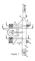
- the mechanism 11 used for axial shifting of intermediate rolls shown in Figure 1 is removed, and a cover 42 is used in its place to cover the exposed end of intermediate roll 13.
- Axial shifting is achieved by a pair of fixed hydraulic cylinders 45, mounted at the back (drive side) of the mill on each side of drive spindle 44 (see Figure 6). These cylinders 45 are used to move shift fingers 46, which engage with matching recesses in ears 47 of thrust housing 43.
- Thrust housing 43 is mounted on bearings on roll 13 (see Figure 6). This structure will be described hereinafter.
- hydraulic cylinders 33 shown in Figure 3, are located in Mae West blocks 35.
- Corresponding hydraulic cylinders 34 are used for counterbending and are also mounted in the Mae West blocks.
- Bending ears 31 are provided on each side of chocks 12 and 16. These project into slots 70 in the Mae West blocks as shown in Figures 4, 5 and 6, and pass through these slots at roll change time when the entire intermediate roll assembly is inserted into and removed from the mill.
- cylinders 33 are retracted, enabling the ears 31 to drop into pockets 72 formed in the Mae West block so that the chocks 12 are axially located in the Mae West blocks so no separate keeper plates are required.
- Ears 40 on front chock cover 42 engage with stop 39 when the roll/chock assembly is first inserted in the mill, to ensure that ears 31 are properly aligned with pockets 72 before the assembly is lowered to the working position shown in Figure 5.
- Ears 31 and pockets 72 constitute keep plate devices for axial location of intermediate rolls 13.
- Wheels 37 and 38 are provided at each side of chocks 12 and 16. Four wheels are used on each chock to bridge the discontinuities in the lower surface 48 of slot 70 in the Mae West bocks, upon which the wheels roll at roll change time. Pockets 71 provide space for wheels 38 to drop into when the assembly is lowered to the working position.
- Wheel lift cylinders 36 mounted in Mae West blocks 35, can raise and lower wheel lift blocks 49, which support wheels 37 to raise the assembly to removal height at the start of roll change cycle. In the extended position of cylinders 36, the top of lift blocks 49 is flush with surface 48. In the retracted position of cylinders 36, block 49 drops down to provide a pocket similar in size to pocket 71, and provides a space for wheels 37 during mill operation.
- the front elevation of Figure 4 shows the upper and lower assemblies at the removal levels, i.e. just after inserting the assemblies into the mill or just before removing them.
- the assemblies are separated by around 200mm relative to their working levels, the upper assembly being raised by substantially half this amount (by extending the upper roll balance cylinders 33), and the lower assembly being lowered by substantially half this amount, (by fully retracting the lower roll counterbending cylinders 34a).
- upper and lower screwdowns should each be opened by about 110 mm at this time, and the wheel lift cylinders 36 should also be extended to provide support for the upper assembly by means of wheels 37.
- chock bending ears 31 disengage from recesses 72 in Mae West blocks, so chocks 12 and 12a are no longer axially located, and also lugs 47 and 47a on thrust housings 43 and 43a (mounted on intermediate rolls 13) disengage from shift fingers 46 and 46a so intermediate rolls 13 and 13a are no longer axially located, thus freeing the assemblies from axial location, and enabling them to be rolled out of the mill.
- the upper work roll 63 is supported by arms (one of which is shown at 75 in Figure 4. Arms 75 (at front and back) are raised and lowered by hydraulic cylinders (not shown) mounted in two of the 4 Mae West blocks 35. During rolling, arms 75 are lowered to the position shown in Figure 5, where they clear the work rolls.
- FIG. 5 The front elevation of Figure 5 shows the upper and lower assemblies at their working levels. It can be seen that the upper chock bending ears 31 have dropped below the upper slot 70 in Mae West block 35, and the lower chock bending ears 31a have lifted above the lower slot 70a. Upper chock bending ears 31 are trapped in pocket 72, and lower chock bending ears are trapped in pocket 72a. It can be seen that at the working levels, counterbending cylinders 34 and 34a operate close to their extended positions, and roll balance/bending cylinders 33 and 33a operate close to their retracted position.
- the upper axial shifting cylinders 45 and shift fingers 46 are located at the mean working level of the upper assembly, and the lower ones (45a and 46a) are located at the mean working level of the lower assembly.
- shift fingers 46, 46a are engaged with lugs 47 and 47a respectively, and shift cylinders can be used (usually under servo control using position feedback provided by transducers 64, 64a mounted on cylinders 45, 45a).
- the invention includes means for performing these tasks without the need for operator intervention.
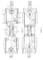
- the front door 50 is shown in Figure 3 and the back door 62 is shown in Figure 7. Details of the hydraulic connection to the chocks are shown in Figures 8 and 9.
- Both front door 50 and back door 62 are mounted on hollow hinge pins 53 and 53', respectively, which fit in hinge blocks (two of which are shown at 52 in Figure 3), mounted on Mae West blocks 35.
- Lubricant usually oil or oil mist, is supplied through hoses (one of which is shown at 78 in Figure 3) to hinge pins 53 and 53' and flows through connecting oil passages 54a and 54a' and 54b and 54b' to chambers 79 and 79' within doors 50 and 62.
- Within the chambers 79 and 79' are upper and lower hollow plungers 57, which are loaded by spring 58 against upper and lower chocks 12, 12a, 16, and 16a when the chocks are at the working level as shown in Figure 9.
- the plungers form a tight seal against the chocks by means of seal rings 57x.
- the lubricant thus flows through hollow plungers 57 and into the connecting oil passage 60 which connects to the roll neck bearing within the chock.
- the plungers are urged apart by spring 58 until they are prevented from further movement by retainers 59, which thus sets a vertical gap between each plunger 57 and each adjacent chock 16, 16a (or 12, 12a) which enables the assemblies to be removed, or the door opened, without any sliding contact between plungers and chocks.
- oil passage 54a and 54a' in doors 50 and 62 are branched so that lubricant is supplied to work roll thrust bearings 51 and 51'via passages 54c and 54c' as well as to roll neck bearings in chocks 12, 12a, 16 and 16a via passages 54b and 54b'.
- Thrust bearings 51, 51' constitute axial location elements for work rolls 63.
- the bearings mounted within cluster arms 15 are lubricated by lubricant passing through hollow pivot shafts 17 (see Figure 6) as in the prior art mill.
- the oil holes in pivot shafts 17 connect to oil holes 61 in rear intermediate roll chocks 16 and 16a.
- Passages 55 (see Figure 7) in back door 62 connect to oil holes 61 (see Figure 6) in exactly the same way described above for the connection of oil passage 54b' (see Figure 7) in back door 62 to holes 60 (see Figure 6) in rear chocks 16. It will be understood that Figure 6 illustrates upper intermediate roll 13.
- holes 60 and 61 are on the underside of upper rear chock 16. Note that there are two holes 61 in each rear chock 16, each hole supplying oil to one cluster arm 15. Hose connections 56 are used to bring lubricant to passages 55 in back door 62. Usually it's not necessary to open the back door at tool change time so these connections can remain undisturbed.
- the front door 50 must be opened at roll change time, and this is why the oil supply to the roll neck bearings in front chocks 12 and 12a and front work roll thrust bearing 51 is brought in through door pivot shaft 53 as shown in Figure 3. In this way it's not necessary to disturb hose connection 73 ( Figure 3) at roll change time.
- a thrust housing 43 is mounted on bearings on the rear neck of intermediate roll 13.
- Thrust bearings 81 used to transmit axial thrust forces
- radial bearings 80 used to maintain concentricity and mounted on sleeves 82 are fitted into each end of the thrust housing, and are retained by snap rings 83.
- Springs 89 are used to preload thrust bearings 81.
- This assembly is then installed by sliding it on to the rear roll neck, up to shoulder 87 and held in place by split ring 84 which fits in a groove on the roll neck and is itself held in place by full ring 86, located by snap ring 85 in the roll neck.
- the thrust housing is prevented from rotating by fork assembly 88 which engages ears 47 on the thrust housing, and are bolted to chock 16. The same structure is present on lower chock 16a.
- shift frames 68 are bolted on to rear Mae West blocks 35 and incorporate keys 91 upon which shift fingers 46 are guided so they are only free to move in a direction parallel to the roll axes.
- Each shift finger 46 can be shifted by its respective hydraulic cylinder 45 which is flange mounted to shift frame 68. As each shift finger 46 engages with the recess in mating ear 47 of the thrust housing, operation of hydraulic cylinders 45 will cause axial shifting of intermediate roll 13.
- both left and right shift cylinders 45 will be connected to a single thrust housing 43.
- Each cylinder being provided with a position transducer 64, (usually of the "Temposonics" type made by M.T.S. Corp.) only one of the transducers will be used for position feedback, and a closed loop position servo will be used to position the cylinder on which that cylinder is mounted (the master cylinder).
- the second cylinder (the slave cylinder) will be connected hydraulically in parallel with the master cylinder. This technique ensures that the two cylinders apply equal shift forces to the thrust housing, thus avoiding bending of the roll neck.
- the two cylinders are hydraulically isolated (using blocking valves, not shown) and each cylinder is positioned by its own closed loop position servo, using its own transducer 64 for feedback.
- This technique ensures that both shift fingers can be properly positioned so that, after new roll assemblies are inserted in the mill, and the intermediate rolls moved vertically (by approximately 100 mm) towards each other to the working position, the shift fingers engage smoothly with recesses in ears 47.
- clamp blocks 65 (see Figure 6 and 10). These blocks are usually curved to match the diameter of coupling 44, but can also be V-shaped as shown in Figure 10. They are attached to clamp plates 93 which are slideably guided in frame 68 on keys 66, which constrain the plates so they can only move in a horizontal direction normal to the roll axes. Each plate 93 is actuated by spindle clamp cylinder 67 which, when extended, will clamp coupling 44 against the force of opposing cylinder 67 through clamp blocks 65. This not only serves to support the spindle weight, but also ensures that, as the rolls are withdrawn and inserted, the drive coupling 44 will not move away from its axial position.
- the drive couplings can be of various designs, such as spade couplings, gear couplings or universal (Hooke's couplings or Cardan couplings). Whichever type of coupling is adopted it is necessary for each spindle to incorporate splines so that the spindle length can adjust to the various axial positions of the intermediate roll 13 as the shift cylinders 45 are operated.
- the roll is provided with a small diameter extension 100 which projects into a matching recess in coupling hub 44.
- This extension is provided with two straight grooves 101 of semi-circular cross section. It is known in the art to provide a transverse hole in coupling 44 which is concentric with one groove 101, and to use a pin mounted in this hole to lock the coupling hub on to the roll. However, such a connection requires manual intervention to remove and install the pin at roll change time.
- the present invention provides for automatic locking and unlocking of the coupling hub on the roll which occurs during release and engagement of the spindle clamps respectively.
- coupling hub 44 is provided with two transverse holes 105, each hole being coaxial with one semi-circular groove 101. Holes 105 are not through holes, but are provided with a reduced diameter portion at one end, thus forming a pocket.
- a compression spring 103 is inserted into each hole and a plunger 102 is pressed against the spring and is retained by retainer 106 which is bolted to coupling hub 44, and which engages with slot 107 in plunger 102. This not only holds the spring lightly preloaded, but also prevents rotation of the plunger about its axis.
- the spring (aided by centrifugal force) presses the plunger against retainer 106, and the full diameter portion of plunger 102 engages with semi-circular groove 101, thus locking the coupling hub 44 on to roll 13 so that if the roll is axially shifted using shift cylinders 45, the coupling hub 44 will move axially with the roll.
- Each plunger 102 is provided with a circular scallop 104 such that, when the plunger is depressed into the hole the required amount, the scallop lines up concentric with roll extension 100, as shown in Figure 11 and the roll is no longer locked into the coupling hub, and can be removed in an axial direction. A new roll can be freely inserted as long as the coupling remains clamped.
- the spindle clamp cylinders 67 can be released, and springs 103 will once again urge plungers 102 towards retainers 106 so that the full diameter portions of the plungers will once again engage grooves 101 in roll extension 100, locking coupling hubs to the rolls.
Landscapes
- Engineering & Computer Science (AREA)
- Mechanical Engineering (AREA)
- Reduction Rolling/Reduction Stand/Operation Of Reduction Machine (AREA)
- Metal Rolling (AREA)
Description
- The invention relates to a 6-high cold rolling mill, and more particularly to such a mill wherein the upper intermediate roll assembly and the lower intermediate roll assembly can be removed and replaced without the necessity of having to manually disconnect or reconnect any lubricating oil or oil mist lines.
- This invention relates to 6-high cold rolling mills having side supported work rolls of the kind described generally in U.S. Patents No. 4,270,377 and 4,531,394. The improvements described herein are of particular use when the rolling mill is part of a continuous line as described generally in U.S. Patent No. 5,197,179.
- U.S. Patent No. 4,531,394 discloses a mill in accordance with the preamble of claim 1.
- The intermediate and work roll area of a 6-high mill according to the prior art is shown in Figure 1 and Figure 2. Salient features of the design are:
- 1. An
adjustment mechanism 11 provides axial shifting of eachintermediate roll 13 by means of hydraulic cylinders and a thrust bearing assembly (not shown). The mechanism is mounted on the operator side intermediate roll chocks 12. This mechanism requires twohydraulic connections 18, and anelectrical connection 19 for a transducer measuring the axial position of the roll. - 2. Lubricating oil or
oil mist connections 14 to the intermediate roll chocks are present to provide lubrication to the intermediate roll neck bearings. - 3. Side support
cluster arm assemblies 15 are each pivotally mounted on a pivot rod (not shown), which spans between the operator side and the drive sideintermediate roll chocks pivot rod 17, which is hollow and so can provide a path to the side support bearings through which the lubricating oil can be delivered throughhoses 20. - 4.
Hydraulic cylinders 21, which are mounted between upper and lowerintermediate roll chocks ports 22, usually four on the drive side and four on the operator side. - 5. Two upper work roll lift assemblies (one of which is shown at 23 in
Figure 2), each consist of a hydraulic cylinder (not shown) connected
to a pivoting support arm used to support the upper work roll when the
mill screwdown is opened, to create a gap between upper and lower
work rolls for threading the mill. These assemblies are mounted on the
upper intermediate roll chocks at the drive and operator sides, and
require two
hydraulic connections 24 to each of these upper chocks. - 6. Keeper plates (one of which is shown at 25 in Figure 1) which can be
hydraulically or manually actuated and are mounted on the Mae West
blocks (shown at 27) attached at the operator side of
mill housing 28. These keeper plates engage withslots 26 in the operator side intermediate roll chocks 12 (or in the housing of thelateral adjustment mechanism 11 which is mounted on these chocks) in order to locate each intermediate roll assembly in its correct axial position in the mill and to support any axial thrust which might develop on the roll assemblies during rolling. -
- These features all provide important functions, and for many applications the features described do a very good job and represent a very cost effective approach. However, singly, or as a group, they suffer from disadvantages under some conditions.
- 1. Apart from feature No. 6 above, they all require hydraulic or lubricating oil connections to the intermediate roll assemblies. Whenever the intermediate rolls are changed, it's necessary to disconnect the pipes, hoses or cables from the assemblies to be removed, and to reconnect the same pipes, hoses or cables to the new intermediate roll assemblies. This takes a fair amount of time, of the order of 15-30 minutes. For cases where intermediate roll changes are infrequent (say fewer than one change per week) the amount of lost time is negligible, but if changes are frequent the amount of lost time is considerable.
- 2. Mounting the axial adjustment mechanism on the operator side intermediate roll chocks (feature 1) means that for every such chock an adjustment mechanism must be supplied. For mills having only two (or perhaps three) sets of chocks this is not a significant disadvantage, because the ability to do maintenance on these mechanisms when the intermediate roll assemblies are out of the mill means that reliable operation can be maintained without additional spares. However, for very high production mills where several intermediate roll assemblies are required, this becomes very expensive, and it would then be an advantage to be able to mount the axial adjustment mechanisms in a fixed position, so that they could be disengaged from the intermediate roll chocks at roll change time.
- 3. A similar situation applies for the case of the intermediate roll balance/bending/counterbending cylinders (feature 4) and for the case of the upper work roll lift assemblies (feature 5). It would be advantageous to remove these items from the intermediate roll assemblies and mount them in fixed positions in the mill so that they can be disengaged from the intermediate roll chocks at roll change time.
- 4. In the case of a mill according to U.S. Patent No. 5,197,179, where it may be necessary to change intermediate rolls with strip in the mill or passing through the mill, the chock mounted balance/bending/counterbending cylinders of feature 4 cannot be used anyway, because the presence of strip in the mill would prevent removal or insertion of the intermediate roll assemblies if such cylinders were installed.
-
- The present inventors have devised an arrangement whereby no hydraulic cylinders are mounted on the intermediate roll chock assemblies, in order to provide improved methods of connecting and disconnecting the lubricating oil supply to these chocks during roll change, that will not require manual intervention.
- The inventors have found that the following features enable the problems of the prior art rolling mills to be overcome.
- 1. Intermediate roll balance/bending, and counterbalance hydraulic cylinders are incorporated in the "Mae West" blocks and so remain in the mill at roll change time. There is no need to make any hydraulic connections/disconnections at this time.
- 2. These cylinders are provided with a long stroke, enabling a large
separation of upper and lower intermediate and work rolls when work
rolls and/or intermediate rolls are changed. This solves four problems
and also enables large clearances between work rolls and strip at roll
change time, avoiding possibility of marking of rolls or strip if the rolls
touch the strip during roll change. The four problems solved are:
- a. It is not necessary to use moveable keeper plates, since the large vertical movement of upper and lower intermediate roll chocks causes them to disengage from the keeper plates, which can now be fixed.
- b. In a similar manner, intermediate roll axial shift fingers, attached to cylinders which are mounted on both sides of each intermediate roll drive spindle, (if intermediate rolls are driven), each engage with a thrust housing associated with one of the intermediate rolls to be changed. It's not necessary to use any other disconnection mechanism - the large vertical movement of the intermediate rolls is enough to disconnect the axial shift fingers from their respective thrust housing. Hydraulic connections to shift cylinders do not have to be touched.
- c. The resulting large gap between work rolls enables the upper work roll support cylinders to be mounted in fixed position on the Mae West blocks, rather than on the upper intermediate roll chocks. These cylinders can thus be permanently piped and there is no need to connect/disconnect them at roll change time.
- d. Spring loaded lubricating oil (or oil mist) connections are mounted on the work roll thrust doors, these connections including spring loaded hollow plungers that operate in the vertical direction, and bear against the inner faces of the intermediate roll chocks. The large vertical separation of the intermediate roll chocks at roll change time causes the intermediate roll chocks to come out of contact with these plungers, enabling the rolls to be removed. It is not necessary to provide any other device to connect and disconnect lubricating oil supply to the chocks and cluster arms at roll change time. The vertical movement of the chocks is sufficient.
-
- The fundamental problem of mounting intermediate roll axial shift cylinders the sides of the drive spindles is that these cylinders occupy the space needed by the spindle clamps - the spindle clamps being essential to support the drive spindles during intermediate roll change. The invention includes means to overcome this problem.
- According to the invention there is provided a 6-high cold rolling mill as set forth in claim 1. The mill is of the type having free floating side supported upper and lower work rolls, chock mounted upper and lower intermediate rolls, and upper and lower back up rolls. The work rolls are axially located by thrust bearings mounted on the front and back doors of the mill. Vertically acting hydraulic cylinders are provided for intermediate roll balancing, bending, counterbalancing, and vertically shifting the upper and lower intermediate rolls toward and away from each other. Horizontal cylinders provide axial shifting adjustment of the intermediate rolls, two cylinder actuated support assemblies are provided to lift the upper work roll to provide a gap between work rolls. All of the hydraulic cylinders above described are mounted on the mill housing assembly and no disconnection and reconnection are required for replacement of the intermediate rolls, or the work rolls, or both. Each intermediate roll assembly supports between its chocks a pair of side support cluster arms. Lubrication to the intermediate roll chocks and cluster arms is provided via spring loaded lubricating oil or oil mist connections mounted on the front and back doors of the mill housing. Upward vertical movement of the upper intermediate rolls and downward vertical. movement of the lower intermediate rolls automatically disconnect the chocks from said spring loaded connections. Movement of the upper and lower intermediate rolls toward each other automatically reconnects the spring loaded connections to the chocks.
-
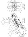
- Figure 1 is an isometric semi-exploded partial view of the side supported 6-high mill according to the prior art.
- Figure 2 is a partial front elevation of the rolls and chocks of a side supported 6-high mill according to the prior art.
- Figure 3 is an isometric semi-exploded partial view of a side supported 6-high mill according to the present invention.
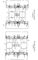
- Figure 4 is a simplified partial front elevation of an upper intermediate roll chock in the removal position.
- Figure 5 is a simplified partial front elevation of an upper intermediate roll chock in the working position.
- Figure 6 is a fragmentary plan view, partly in cross-section, illustrating an upper intermediate roll assembly mounted in the mill.
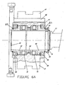
- Figure 6a is a fragmentary plan view, partly in cross-section, constituting an enlarged portion of Figure 6.
- Figure 7 is a plan view of the rear work roll thrust door with lubrication connections.
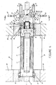
- Figure 8 is a fragmentary cross-sectional view taken along either section line 8-8 of Figure 7.
- Figure 9 is a fragmentary cross-sectional view taken along section line 9-9 of Figure 7.
- Figure 10 is a fragmentary cross-sectional view taken along section line 10-10 of Figure 6 and showing spindle clamps in the open position.
- Figure 11 is a fragmentary cross-sectional view, similar to Figure 10 and showing spindle clamps in the closed position.
-
- The salient features of the prior art side supported 6-high rolling mill are shown in Figures 1 and 2 and described in the introduction. The intermediate roll assembly shown in Figure 1 is mounted in the window of rolling
mill housings 28, within the gap formed by "Mae West" blocks 27, and side support beams 29 which span between operator side and drive side "Mae West" blocks. The prior art mill also includes work rolls which float freely in the mill (these are shown at 63 in Figure 2) and which are axially located by means of work roll thrust bearings mounted in pivoting doors (not shown) at the front (operator side) and back (drive side) of the mill. - A mill according to one embodiment of the present invention is shown in Figure 3. In Figure 3 like numerals refer to like parts of the prior art mill of Figure 1. In Figure 3 the work rolls and back door are omitted for the sake of clarity. Figure 3 can be compared with Figure 1 in order to obtain a clear picture of the novel features. The following description applies to the upper intermediate roll assembly. It is to be understood that the arrangement is essentially symmetrical about a fixed horizontal pass line, so the lower assembly is the same as the upper, but inverted. Like parts of the lower intermediate roll assembly have been given like index numerals, followed by "a".
- The
intermediate roll 13 is mounted inchocks cluster arms 15 are mounted on pivot rods 17 (see Figure 6) spanning betweenchocks housings 28. Side support beams 29 (one of which is shown in Figure 3) span between front and rear Mac West blocks 35. - The
mechanism 11 used for axial shifting of intermediate rolls shown in Figure 1 is removed, and acover 42 is used in its place to cover the exposed end ofintermediate roll 13. Axial shifting is achieved by a pair of fixedhydraulic cylinders 45, mounted at the back (drive side) of the mill on each side of drive spindle 44 (see Figure 6). Thesecylinders 45 are used to moveshift fingers 46, which engage with matching recesses inears 47 ofthrust housing 43.Thrust housing 43 is mounted on bearings on roll 13 (see Figure 6). This structure will be described hereinafter. - To provide for intermediate roll balance and roll bending,
hydraulic cylinders 33, shown in Figure 3, are located in Mae West blocks 35. Correspondinghydraulic cylinders 34 are used for counterbending and are also mounted in the Mae West blocks. Bendingears 31 are provided on each side ofchocks slots 70 in the Mae West blocks as shown in Figures 4, 5 and 6, and pass through these slots at roll change time when the entire intermediate roll assembly is inserted into and removed from the mill. After the intermediate rolls are changed,cylinders 33 are retracted, enabling theears 31 to drop intopockets 72 formed in the Mae West block so that thechocks 12 are axially located in the Mae West blocks so no separate keeper plates are required.Ears 40 on front chock cover 42 engage with stop 39 when the roll/chock assembly is first inserted in the mill, to ensure thatears 31 are properly aligned withpockets 72 before the assembly is lowered to the working position shown in Figure 5.Ears 31 andpockets 72 constitute keep plate devices for axial location of intermediate rolls 13. -
Wheels chocks lower surface 48 ofslot 70 in the Mae West bocks, upon which the wheels roll at roll change time.Pockets 71 provide space forwheels 38 to drop into when the assembly is lowered to the working position.Wheel lift cylinders 36, mounted in Mae West blocks 35, can raise and lower wheel lift blocks 49, which supportwheels 37 to raise the assembly to removal height at the start of roll change cycle. In the extended position ofcylinders 36, the top of lift blocks 49 is flush withsurface 48. In the retracted position ofcylinders 36, block 49 drops down to provide a pocket similar in size topocket 71, and provides a space forwheels 37 during mill operation. It should be noted here that, although the Mae West structure is essentially symmetrical about the horizontal pass line, it's not necessary to usecylinders 36 at the bottom, because gravity will bring the lower assembly from working position to the removal position when lower counterbending cylinders 34a are retracted. - The front elevation of Figure 4 shows the upper and lower assemblies at the removal levels, i.e. just after inserting the assemblies into the mill or just before removing them. When at this level, the assemblies are separated by around 200mm relative to their working levels, the upper assembly being raised by substantially half this amount (by extending the upper roll balance cylinders 33), and the lower assembly being lowered by substantially half this amount, (by fully retracting the lower roll counterbending cylinders 34a). It should be noted that upper and lower screwdowns (not shown) should each be opened by about 110 mm at this time, and the
wheel lift cylinders 36 should also be extended to provide support for the upper assembly by means ofwheels 37. If thecylinders 33 are now retracted, the upper and lower assemblies will be at the removal levels, the upper assembly'swheels 37 resting on support blocks 49, and the lower assembly'swheels front door 50, by releasing the door latch (not shown) and swinging the door open (the door is hinged onpin 53 mounted in pivot block 52), it is possible to roll the upper and lower assemblies in or out of the mill at this level (of course roll change actuator and external rails, not shown, are required to do this). It should also be noted that, when the assemblies are separated to the removal levels shown in Figure 4, chock bendingears 31 disengage fromrecesses 72 in Mae West blocks, so chocks 12 and 12a are no longer axially located, and also lugs 47 and 47a onthrust housings 43 and 43a (mounted on intermediate rolls 13) disengage fromshift fingers 46 and 46a sointermediate rolls 13 and 13a are no longer axially located, thus freeing the assemblies from axial location, and enabling them to be rolled out of the mill. - At roll change time the
upper work roll 63 is supported by arms (one of which is shown at 75 in Figure 4. Arms 75 (at front and back) are raised and lowered by hydraulic cylinders (not shown) mounted in two of the 4 Mae West blocks 35. During rolling,arms 75 are lowered to the position shown in Figure 5, where they clear the work rolls. - The front elevation of Figure 5 shows the upper and lower assemblies at their working levels. It can be seen that the upper
chock bending ears 31 have dropped below theupper slot 70 inMae West block 35, and the lower chock bending ears 31a have lifted above the lower slot 70a. Upperchock bending ears 31 are trapped inpocket 72, and lower chock bending ears are trapped in pocket 72a. It can be seen that at the working levels,counterbending cylinders 34 and 34a operate close to their extended positions, and roll balance/bending cylinders 33 and 33a operate close to their retracted position. - The upper
axial shifting cylinders 45 and shift fingers 46 (Figure 3 and Figure 7) are located at the mean working level of the upper assembly, and the lower ones (45a and 46a) are located at the mean working level of the lower assembly. Thus, when the assemblies (includingthrust housings 43, 43a and theirlugs 47, 47a) are at the working level, shiftfingers 46, 46a are engaged withlugs 47 and 47a respectively, and shift cylinders can be used (usually under servo control using position feedback provided bytransducers 64, 64a mounted oncylinders 45, 45a). - There are two more factors that have to be considered before the assemblies can be safely removed from the mill. Firstly the lubrication connections to the chocks must be removed and secondly, the
drive spindles 44 and 44a must be disconnected. The invention includes means for performing these tasks without the need for operator intervention. - The
front door 50 is shown in Figure 3 and theback door 62 is shown in Figure 7. Details of the hydraulic connection to the chocks are shown in Figures 8 and 9. - Both
front door 50 andback door 62 are mounted on hollow hinge pins 53 and 53', respectively, which fit in hinge blocks (two of which are shown at 52 in Figure 3), mounted on Mae West blocks 35. Lubricant, usually oil or oil mist, is supplied through hoses (one of which is shown at 78 in Figure 3) to hingepins 53 and 53' and flows through connecting oil passages 54a and 54a' and 54b and 54b' to chambers 79 and 79' withindoors hollow plungers 57, which are loaded byspring 58 against upper andlower chocks hollow plungers 57 and into the connectingoil passage 60 which connects to the roll neck bearing within the chock. When the assemblies are opened to the removal level, the plungers are urged apart byspring 58 until they are prevented from further movement byretainers 59, which thus sets a vertical gap between eachplunger 57 and eachadjacent chock 16, 16a (or 12, 12a) which enables the assemblies to be removed, or the door opened, without any sliding contact between plungers and chocks. - It should be noted that oil passage 54a and 54a' in
doors roll thrust bearings 51 and 51'via passages 54c and 54c' as well as to roll neck bearings inchocks Thrust bearings 51, 51' constitute axial location elements for work rolls 63. - The bearings mounted within
cluster arms 15 are lubricated by lubricant passing through hollow pivot shafts 17 (see Figure 6) as in the prior art mill. However, instead of supplying oil directly by hose connections to the pivot shafts (as is done in prior art mills, and which requires connections to be broken and made at roll change time) the oil holes inpivot shafts 17 connect tooil holes 61 in rear intermediate roll chocks 16 and 16a. Passages 55 (see Figure 7) inback door 62 connect to oil holes 61 (see Figure 6) in exactly the same way described above for the connection of oil passage 54b' (see Figure 7) inback door 62 to holes 60 (see Figure 6) inrear chocks 16. It will be understood that Figure 6 illustrates upperintermediate roll 13. Thus holes 60 and 61 are on the underside of upperrear chock 16. Note that there are twoholes 61 in eachrear chock 16, each hole supplying oil to onecluster arm 15.Hose connections 56 are used to bring lubricant topassages 55 inback door 62. Usually it's not necessary to open the back door at tool change time so these connections can remain undisturbed. - The
front door 50 must be opened at roll change time, and this is why the oil supply to the roll neck bearings in front chocks 12 and 12a and front work roll thrustbearing 51 is brought in throughdoor pivot shaft 53 as shown in Figure 3. In this way it's not necessary to disturb hose connection 73 (Figure 3) at roll change time. - The arrangement for axial shifting of each intermediate roll is shown in Figure 6 and Figure 6a.
- First, a
thrust housing 43 is mounted on bearings on the rear neck ofintermediate roll 13.Thrust bearings 81, used to transmit axial thrust forces, andradial bearings 80, used to maintain concentricity and mounted onsleeves 82 are fitted into each end of the thrust housing, and are retained by snap rings 83.Springs 89 are used to preloadthrust bearings 81. - This assembly is then installed by sliding it on to the rear roll neck, up to
shoulder 87 and held in place by split ring 84 which fits in a groove on the roll neck and is itself held in place byfull ring 86, located bysnap ring 85 in the roll neck. The thrust housing is prevented from rotating byfork assembly 88 which engagesears 47 on the thrust housing, and are bolted to chock 16. The same structure is present on lower chock 16a. - As shown in figure 6, shift frames 68 are bolted on to rear Mae West blocks 35 and incorporate
keys 91 upon which shiftfingers 46 are guided so they are only free to move in a direction parallel to the roll axes. Eachshift finger 46 can be shifted by its respectivehydraulic cylinder 45 which is flange mounted to shiftframe 68. As eachshift finger 46 engages with the recess inmating ear 47 of the thrust housing, operation ofhydraulic cylinders 45 will cause axial shifting ofintermediate roll 13. - During operation of the mill, both left and
right shift cylinders 45 will be connected to asingle thrust housing 43. Each cylinder being provided with aposition transducer 64, (usually of the "Temposonics" type made by M.T.S. Corp.) only one of the transducers will be used for position feedback, and a closed loop position servo will be used to position the cylinder on which that cylinder is mounted (the master cylinder). At this time the second cylinder (the slave cylinder) will be connected hydraulically in parallel with the master cylinder. This technique ensures that the two cylinders apply equal shift forces to the thrust housing, thus avoiding bending of the roll neck. - At roll change time, when the intermediate rolls are separated so that the thrust housing ears disengage from the shift fingers, the two cylinders are hydraulically isolated (using blocking valves, not shown) and each cylinder is positioned by its own closed loop position servo, using its
own transducer 64 for feedback. This technique ensures that both shift fingers can be properly positioned so that, after new roll assemblies are inserted in the mill, and the intermediate rolls moved vertically (by approximately 100 mm) towards each other to the working position, the shift fingers engage smoothly with recesses inears 47. - During normal operation of the mill, the weight of the mill drive spindles and their
couplings 44 is supported byintermediate rolls 13. When the rolls are withdrawn from the mill at roll change time it is necessary to support the spindles and couplings by separate means. This function is provided by clamp blocks 65 (see Figure 6 and 10). These blocks are usually curved to match the diameter ofcoupling 44, but can also be V-shaped as shown in Figure 10. They are attached to clampplates 93 which are slideably guided inframe 68 onkeys 66, which constrain the plates so they can only move in a horizontal direction normal to the roll axes. Eachplate 93 is actuated byspindle clamp cylinder 67 which, when extended, will clampcoupling 44 against the force of opposingcylinder 67 through clamp blocks 65. This not only serves to support the spindle weight, but also ensures that, as the rolls are withdrawn and inserted, thedrive coupling 44 will not move away from its axial position. -
Slot 96 is provided inclamp plate 93 andpiston rod 95 ofshift cylinder 45 passes through this slot. Thus theshift cylinder 45 andspindle clamp cylinder 67 can operate independently. It should be noted here that thespindle clamp cylinder 67 andspindle clamp block 65 andplate 93 must be positioned to clamp the spindles when therolls 13 are set to the removal level (Figure 4). Whereas theaxial shift cylinder 45,piston rod 95 andshift finger 46 must be set to the mean working level (Figure 5). Thus the slot inclamp plate 93 must be positioned approximately 100 mm away from its center line, and this plate must be very deep (approximately 300 mm) so that it can contain this slot without being unduly weakened by the slot. The structure can be seen, for a typical upper assembly, in Figure 10, where a = 100 mm approximately. - As is well known in the art, the drive couplings can be of various designs, such as spade couplings, gear couplings or universal (Hooke's couplings or Cardan couplings). Whichever type of coupling is adopted it is necessary for each spindle to incorporate splines so that the spindle length can adjust to the various axial positions of the
intermediate roll 13 as theshift cylinders 45 are operated. - To ensure that each roll 13 remains fully engaged with coupling hub 44 (see Figure 6) at all times during rolling, the roll is provided with a
small diameter extension 100 which projects into a matching recess incoupling hub 44. This extension is provided with twostraight grooves 101 of semi-circular cross section. It is known in the art to provide a transverse hole incoupling 44 which is concentric with onegroove 101, and to use a pin mounted in this hole to lock the coupling hub on to the roll. However, such a connection requires manual intervention to remove and install the pin at roll change time. The present invention provides for automatic locking and unlocking of the coupling hub on the roll which occurs during release and engagement of the spindle clamps respectively. - As is shown in Figure 10,
coupling hub 44 is provided with twotransverse holes 105, each hole being coaxial with onesemi-circular groove 101.Holes 105 are not through holes, but are provided with a reduced diameter portion at one end, thus forming a pocket. Acompression spring 103 is inserted into each hole and aplunger 102 is pressed against the spring and is retained byretainer 106 which is bolted tocoupling hub 44, and which engages withslot 107 inplunger 102. This not only holds the spring lightly preloaded, but also prevents rotation of the plunger about its axis. - In the position shown, the normal operating position, the spring (aided by centrifugal force) presses the plunger against
retainer 106, and the full diameter portion ofplunger 102 engages withsemi-circular groove 101, thus locking thecoupling hub 44 on to roll 13 so that if the roll is axially shifted usingshift cylinders 45, thecoupling hub 44 will move axially with the roll. - At roll change time, when the
spindle clamp cylinders 67 are operated, as shown in Figure 11,clamp plates 93 depressplungers 102 the required amount at the same time that they clampcoupling hub 44. - Each
plunger 102 is provided with acircular scallop 104 such that, when the plunger is depressed into the hole the required amount, the scallop lines up concentric withroll extension 100, as shown in Figure 11 and the roll is no longer locked into the coupling hub, and can be removed in an axial direction. A new roll can be freely inserted as long as the coupling remains clamped. - After inserting new rolls, and ensuring that they are fully engaged with the coupling hubs, the
spindle clamp cylinders 67 can be released, and springs 103 will once again urgeplungers 102 towardsretainers 106 so that the full diameter portions of the plungers will once again engagegrooves 101 inroll extension 100, locking coupling hubs to the rolls. - Modifications can be made in the invention without departing from the definition given by the appended claims.
Claims (14)
- A 6-high cold rolling mill having a pass line, free floating work rolls (63), intermediate rolls (13) having neck bearings mounted in chocks (12, 12a, 16, 16a), backup rolls, operator side and drive side doors (50, 62), thrust bearings (51, 51') on said doors constituting axial location elements for said work rolls (63), side support assemblies for said work rolls (63), vertically acting hydraulic cylinders (33, 33a, 34, 34a) for intermediate roll bending, balancing, and counterbalancing, for vertical shifting of said intermediate rolls (13) between their working levels and their removal levels, and vertically acting hydraulic cyclinders for support of the upper work roll at roll change time, horizontally acting hydraulic cylinders (45, 45a) for intermediate roll shifting, keeper plate devices (31, 72) for axial location of said intermediate rolls (13), and oil connection devices (57, 62) for lubrication of said intermediate roll neck bearings and said side support assemblies, characterized by means for automatically completely separating the upper and lower intermediate rolls (13), their chocks (12, 12a; 16, 16a) and their side support assemblies from all hydraulic cylinders, keeper plate devices, and oil connection devices, so that they may be removed from the mill by shifting them axially toward the operator side, when all the upper and lower rolls are shifted vertically away from said pass line.
- The mill claimed in claim 1, wherein said upper and lower intermediate rolls (13) are driven by upper and lower intermediate roll drive spindles (44, 44a) and upper and lower spindle clamp assemblies (66-68, 93-96) clamp and support said upper and lower drive spindles during the removal from said mill and the insertion in said mill of said upper and lower intermediate rolls (13), their chocks (12, 12a, 16, 16a) and their side support assemblies.
- The mill claimed in claim 1, wherein said oil connection devices for lubrication of said intermediate roll neck bearings comprise vertically acting, oppositely directed, hollow spring plungers (57) mounted on said operator side and drive side doors (50, 62), the upper and lower operator side chocks (12, 12a) and the upper and lower drive side chocks (16, 16a) having facing upper and lower surfaces with holes (60) therein connected by oil passages to said neck bearings, and when said intermediate rolls (13) are at their working levels each plunger (57) engages and forms a fluid-tight seal with its respective chock hole (60), said plungers being disconnected from their respective chock holes when said upper and lower intermediate rolls (13) are at their removal levels.
- The mill claimed in claim 1, wherein said oil connection devices for lubrication of said work roll side support assembies comprise vertically acting, oppositely directed, hollow spring plungers (57) mounted on said drive side door (62), the upper and lower drive side chocks (16, 16a) having facing upper and lower surfaces with holes (61) therein connected by oil passages to side support assemblies, and when said intermediate rolls (13) are at their working levels, each plunger (57) engages and forms a fluid-tight seal with its respective chock hole (61), said plungers being disconnected from their respective chock holes when said upper and lower intermediate rolls (13) are shifted to their removal levels.
- The mill claimed in claim 1, including a pair mill housings (28), a left side front and rear pair and a right side front and rear pair of Mae West blocks (35) being mounted in said housings, a side support beam (29) spanning between the front and rear Mae West blocks of each pair, all of said hydraulic cylinders being mounted in or on said Mae West blocks, whereby said hydraulic cylinders need not be removed with said intermediate rolls (13) and no hydraulic disconnection or connection is required.
- The mill claimed in claim 1, wherein said keeper plate devices comprise ears (31) on the operator side, upper and lower intermediate roll chocks, each ear engaging a pocket (72) of a respective Mae West block (35) when said upper and lower intermediate rolls (13) are at their working levels, and disengaging from said pocket when said rolls are at their removal levels.
- The mill claimed in claim 1, including for each upper and lower intermediate roll (13) a driven end, a thrust housing (43, 43a) mounted on said driven end, a pair of shift fingers (46, 46a) for each thrust housing, a pair of recesses formed by lugs (47) in each thrust housing engageable by said shift fingers for that housing, each shift finger of each pair being mounted on a rod (95) shiftable axially by an actuator (45, 45a) to axially adjust said upper and lower intermediate rolls (13), said shift fingers automatically disengaging from their respective thrust housing when said upper and lower intermediate rolls are shifted to their removal levels and re-engaging when said upper and lower intermediate rolls are shifted to their working levels.
- The mill claimed in claim 2 including a driven end for each upper and lower intermediate roll (13), a thrust housing (43, 43a) at each driven end, a pair of shift fingers (46, 46a) for each thrust housing, a pair of diametric recesses formed by lugs (47) in each thrust housing engageable by said shift fingers for that housing, each shift finger of each pair being mounted on a rod (95) shiftable axially by an actuator (45, 45a) to axially adjust said upper and lower intermediate rolls (13), said shift fingers disengaging from their respective thrust housing when said upper and lower intermediate rolls are shifted from their working levels to their removal levels and re-engaging when said upper and lower intermediate rolls are shifted from their removal levels to their working levels.
- The mill claimed in claim 8, wherein said spindle clamp assemblies comprise hydraulically actuated plates (96) on each side of each intermediate roll drive spindle, said rod (95) of each shift finger passing through a slot in the adjacent one of said plates.
- The mill claimed in claim 3, wherein said oil connection devices for lubrication of said work roll side support assemblies comprise vertically acting, oppositely directed, hollow spring plungers (57) mounted on said drive side door (62), the upper and lower drive side chocks (16, 16a) having facing upper and lower surfaces with holes (61) therein connected by oil passages to said side support assemblies so that when said intermediate rolls (13) are at their working levels, each plunger (57) engages and forms a fluid-tight seal with its respective chock hole (61), said plungers disengaging from their respective chock holes when said upper and lower intermediate rolls (13) are shifted to their removal levels.
- The mill claimed in claim 10, including a pair of mill housings (28), a left side front and rear pair and a right side front and rear pair of Mae West blocks (35) being mounted in said housings, a side support beam (29) spanning between the front and rear Mae West blocks of each pair, all of said hydraulic cylinders being mounted in or on said Mae West blocks, whereby said hydraulic cylinders need not be removed with said intermediate rolls (13) and no hydraulic disconnection or connection is required.
- The mill claimed in claim 11, wherein said keeper plate devices comprise ears (31) on said front and rear, upper and lower intermediate roll chocks, each ear engaging a pocket (72) of its respective one of said Mae West blocks (35) when said upper and lower intermediate rolls (13) are at their working levels, and disengaging from said pocket when said rolls are at their removal levels.
- The mill claimed in any of claims 10 to 12, including for each upper and lower intermediate roll (13) a driven end, a thrust housing (43, 43a) mounted on said driven end, a pair of shift fingers (46, 46a) for each thrust housing, a pair of recesses formed by lugs (47) in each thrust housing engageable by said shift fingers for that housing, each shift finger for each pair being mounted on a rod (95) shiftable axially by an actuator (45, 45a) to axially adjust said upper and lower intermediate rolls (13), said shift fingers automatically disengaging from their respective thrust housing when said upper and lower intermediate rolls (13) are shifted to their removal levels.
- The mill claimed in any of claims 10 to 12, including a driven end for each upper and lower intermediate roll (13), a thrust housing (43, 43a) at each driven end, a pair of shift fingers (46, 46a) for each thrust housing, a pair of diametric recesses formed by lugs (47) in each thrust housing engageable by said shift fingers for that housing, each shift finger of each pair being mounted on a rod (95) shiftable axially by an actuator (45, 45a) to axially adjust said upper and lower intermediate rolls (13), said shift fingers automatically disengaging from their respective thrust housing when said upper and lower intermediate rolls (13) are shifted from their working levels to their removal levels and re-engaging when said upper and lower intermediate rolls are shifted from their removal levels to their working levels.
Applications Claiming Priority (2)
| Application Number | Priority Date | Filing Date | Title |
|---|---|---|---|
| US27062 | 1998-02-20 | ||
| US09/027,062 US6041636A (en) | 1998-02-20 | 1998-02-20 | Side supported 6-high rolling mill |
Publications (3)
| Publication Number | Publication Date |
|---|---|
| EP0937517A2 EP0937517A2 (en) | 1999-08-25 |
| EP0937517A3 EP0937517A3 (en) | 2002-03-27 |
| EP0937517B1 true EP0937517B1 (en) | 2003-10-15 |
Family
ID=21835456
Family Applications (1)
| Application Number | Title | Priority Date | Filing Date |
|---|---|---|---|
| EP98306423A Expired - Lifetime EP0937517B1 (en) | 1998-02-20 | 1998-08-12 | Improved side supported 6-high rolling mill |
Country Status (4)
| Country | Link |
|---|---|
| US (1) | US6041636A (en) |
| EP (1) | EP0937517B1 (en) |
| JP (1) | JP4434339B2 (en) |
| DE (1) | DE69818967T2 (en) |
Cited By (1)
| Publication number | Priority date | Publication date | Assignee | Title |
|---|---|---|---|---|
| CN103191921A (en) * | 2012-01-04 | 2013-07-10 | 意大利米诺公司 | Multi-roll rolling mill, in particular of the six-high type |
Families Citing this family (19)
| Publication number | Priority date | Publication date | Assignee | Title |
|---|---|---|---|---|
| FR2824764B1 (en) * | 2001-05-18 | 2003-10-03 | Vai Clecim | DEVICE FOR DISASSEMBLING THE CYLINDERS OF A ROLLER |
| KR100507636B1 (en) * | 2002-11-26 | 2005-08-10 | 주식회사 포스코 | Fixing and reform apparatus of spindle for replace backup roll |
| KR100979048B1 (en) * | 2007-05-09 | 2010-08-30 | 주식회사 포스코 | Rolling Mill Support Device |
| KR100940725B1 (en) * | 2007-06-18 | 2010-02-08 | 주식회사 포스코 | Balance cylinder device of rolling roll choke |
| CN101549354B (en) * | 2008-04-01 | 2011-03-16 | 中冶赛迪工程技术股份有限公司 | Six-roller mill |
| JP5669403B2 (en) * | 2009-01-20 | 2015-02-12 | 株式会社神戸製鋼所 | Cluster-type multi-high rolling mill with roll offset mechanism |
| WO2011107165A1 (en) | 2010-03-03 | 2011-09-09 | Siemens Vai Metals Technologies Sas | Roll stand |
| CN102441574B (en) * | 2011-09-22 | 2013-12-18 | 常州宝菱重工机械有限公司 | Shaft supporting frame device for four- and six-roll interchange rolling mill |
| KR101403232B1 (en) * | 2011-11-17 | 2014-06-02 | 주식회사 포스코 | Apparatus for control of roll chock's balancing |
| JP5828833B2 (en) * | 2012-12-25 | 2015-12-09 | 株式会社神戸製鋼所 | Cluster type multi-high rolling mill |
| FR3008633B1 (en) | 2013-07-22 | 2015-08-07 | Fives Dms | ROLLER EQUIPPED WITH AT LEAST ONE COOLING NOZZLE |
| FR3010332B1 (en) | 2013-09-12 | 2015-10-02 | Fives Dms | CASSETTE FOR ROLLING MILL AND ROLLING MACHINE EQUIPPED WITH SUCH A CASSETTE |
| FR3056419B1 (en) * | 2016-09-27 | 2018-10-12 | Fives Dms | DEVICE FOR SPINNING A METAL STRIP |
| FR3077015B1 (en) | 2018-01-25 | 2020-01-24 | Fives Dms | ROLLER WITH COOLING OR LUBRICATING DEVICE |
| FR3078494B1 (en) | 2018-03-05 | 2021-12-17 | Fives Dms | LAMINATION PROCESS WITH STEP FOR ADJUSTING THE INTERSPACE BETWEEN THE SIDE SUPPORT CYLINDER AND THE SUPPORT CYLINDER |
| CN115397573B (en) * | 2020-08-07 | 2024-10-25 | 普锐特冶金技术日本有限公司 | Rolling mill, control method of rolling mill and thrust bearing method in rolling mill |
| CN113333472B (en) * | 2021-08-08 | 2021-10-12 | 常州市坚力橡胶有限公司 | Rubber roll and machine tool assembled by same |
| CN115634934B (en) * | 2022-11-10 | 2025-07-15 | 中冶南方工程技术有限公司 | Multi-roller mill with split front door and operating method thereof |
| JP7810139B2 (en) * | 2023-03-27 | 2026-02-03 | Jfeスチール株式会社 | Rolling mill for plate rolling, method for controlling roll reduction position of rolling mill, and method for manufacturing rolled plate |
Family Cites Families (6)
| Publication number | Priority date | Publication date | Assignee | Title |
|---|---|---|---|---|
| US3864955A (en) * | 1973-12-04 | 1975-02-11 | Blaw Knox Foundry Mill Machine | Rolling mill stand |
| US4270377A (en) * | 1978-05-19 | 1981-06-02 | T. Sendzimir, Inc. | Eighteen high rolling mill |
| US4531394A (en) * | 1982-03-26 | 1985-07-30 | T. Sendzimir, Inc. | Six-high rolling mills |
| EP0235332B1 (en) * | 1986-03-04 | 1990-10-03 | MANNESMANN Aktiengesellschaft | Rolling mill stand |
| US5197170A (en) * | 1989-11-18 | 1993-03-30 | Murata Manufacturing Co., Ltd. | Method of producing an LC composite part and an LC network part |
| ATE162436T1 (en) * | 1993-11-29 | 1998-02-15 | Danieli Off Mecc | DEVICE FOR AXIAL TIGHTENING/LOOSENING OF THE ROLLER CLAMPING PIECES IN A ROLL STAND |
-
1998
- 1998-02-20 US US09/027,062 patent/US6041636A/en not_active Expired - Lifetime
- 1998-08-12 DE DE69818967T patent/DE69818967T2/en not_active Expired - Lifetime
- 1998-08-12 EP EP98306423A patent/EP0937517B1/en not_active Expired - Lifetime
- 1998-09-21 JP JP26628898A patent/JP4434339B2/en not_active Expired - Fee Related
Cited By (1)
| Publication number | Priority date | Publication date | Assignee | Title |
|---|---|---|---|---|
| CN103191921A (en) * | 2012-01-04 | 2013-07-10 | 意大利米诺公司 | Multi-roll rolling mill, in particular of the six-high type |
Also Published As
| Publication number | Publication date |
|---|---|
| US6041636A (en) | 2000-03-28 |
| DE69818967T2 (en) | 2004-09-09 |
| JPH11254005A (en) | 1999-09-21 |
| EP0937517A3 (en) | 2002-03-27 |
| JP4434339B2 (en) | 2010-03-17 |
| EP0937517A2 (en) | 1999-08-25 |
| DE69818967D1 (en) | 2003-11-20 |
Similar Documents
| Publication | Publication Date | Title |
|---|---|---|
| US6041636A (en) | Side supported 6-high rolling mill | |
| US4531394A (en) | Six-high rolling mills | |
| US7165432B2 (en) | Method and device for changing pairs of working rolls and/or pairs of back-up rolls on roll stands | |
| CN208976508U (en) | Roller mill roll bending and shifting device | |
| US2911804A (en) | Rolling mill coupling | |
| JPH0234681B2 (en) | ||
| EP0443725B1 (en) | Roll with width adjusting function | |
| US5596898A (en) | Device for the axial clamping/release of the chocks of the rolls in a rolling mill stand | |
| CN105745033B (en) | Box for a rolling mill and a rolling mill with such a box | |
| US5752404A (en) | Roll shifting system for rolling mills | |
| US3878703A (en) | Rolling mills | |
| US4274274A (en) | Rolling mills | |
| CN101346195A (en) | Device for rotationally locking the back-up roll balance mechanism of a rolling mill stand | |
| US3383897A (en) | Vertical mill | |
| US4352229A (en) | Bearing retaining and positioning means | |
| EP1344581A1 (en) | Roll changing device for a rolling mill | |
| US6217081B1 (en) | Device for coupling and uncoupling the media supply lines at bearing chocks of rolls, particularly back-up rolls, mounted in roll housings | |
| US4693106A (en) | Apparatus for axially shifting rolls in a roll stand | |
| EP1184095A2 (en) | Method and apparatus for interchanging ring rolls of a bar and wire rod mill | |
| RU2301124C2 (en) | Multiroll mill stand, particularly, six high cluster mill stand with device for axial displacement and interlocking for intermediate and/or work rolls installed for movement | |
| WO2002024357A1 (en) | Device to absorb the axial loads generated on the rolls in a rolling stand | |
| EP1042083B1 (en) | Bending block for four-high rolling stand | |
| US2102809A (en) | Rolling mill housing | |
| EP0950440A1 (en) | Device to remove working rolls in a four-high rolling stand | |
| EP0488022B1 (en) | Support for rolling rings on rolling stands having rolls supported as cantilevers |
Legal Events
| Date | Code | Title | Description |
|---|---|---|---|
| PUAI | Public reference made under article 153(3) epc to a published international application that has entered the european phase |
Free format text: ORIGINAL CODE: 0009012 |
|
| AK | Designated contracting states |
Kind code of ref document: A2 Designated state(s): AT BE CH CY DE DK ES FI FR GB GR IE IT LI LU MC NL PT SE Kind code of ref document: A2 Designated state(s): DE FR GB IT |
|
| AX | Request for extension of the european patent |
Free format text: AL;LT;LV;MK;RO;SI |
|
| PUAL | Search report despatched |
Free format text: ORIGINAL CODE: 0009013 |
|
| AK | Designated contracting states |
Kind code of ref document: A3 Designated state(s): AT BE CH CY DE DK ES FI FR GB GR IE IT LI LU MC NL PT SE |
|
| AX | Request for extension of the european patent |
Free format text: AL;LT;LV;MK;RO;SI |
|
| 17P | Request for examination filed |
Effective date: 20020430 |
|
| AKX | Designation fees paid |
Free format text: DE FR GB IT |
|
| 17Q | First examination report despatched |
Effective date: 20021108 |
|
| GRAH | Despatch of communication of intention to grant a patent |
Free format text: ORIGINAL CODE: EPIDOS IGRA |
|
| RIN1 | Information on inventor provided before grant (corrected) |
Inventor name: YOUNG, LUCAS M. Inventor name: GUILLOT, YVES Inventor name: DATZUK, ALEXANDER |
|
| GRAS | Grant fee paid |
Free format text: ORIGINAL CODE: EPIDOSNIGR3 |
|
| GRAA | (expected) grant |
Free format text: ORIGINAL CODE: 0009210 |
|
| AK | Designated contracting states |
Kind code of ref document: B1 Designated state(s): DE FR GB IT |
|
| REG | Reference to a national code |
Ref country code: GB Ref legal event code: FG4D |
|
| RIN1 | Information on inventor provided before grant (corrected) |
Inventor name: YOUNG, LUCAS M. Inventor name: GUILLOT, YVES Inventor name: DATZUK, ALEXANDER |
|
| REG | Reference to a national code |
Ref country code: IE Ref legal event code: FG4D |
|
| REF | Corresponds to: |
Ref document number: 69818967 Country of ref document: DE Date of ref document: 20031120 Kind code of ref document: P |
|
| ET | Fr: translation filed | ||
| PLBE | No opposition filed within time limit |
Free format text: ORIGINAL CODE: 0009261 |
|
| STAA | Information on the status of an ep patent application or granted ep patent |
Free format text: STATUS: NO OPPOSITION FILED WITHIN TIME LIMIT |
|
| 26N | No opposition filed |
Effective date: 20040716 |
|
| REG | Reference to a national code |
Ref country code: IE Ref legal event code: MM4A |
|
| REG | Reference to a national code |
Ref country code: FR Ref legal event code: PLFP Year of fee payment: 19 |
|
| PGFP | Annual fee paid to national office [announced via postgrant information from national office to epo] |
Ref country code: DE Payment date: 20160809 Year of fee payment: 19 Ref country code: GB Payment date: 20160810 Year of fee payment: 19 Ref country code: IT Payment date: 20160822 Year of fee payment: 19 |
|
| PGFP | Annual fee paid to national office [announced via postgrant information from national office to epo] |
Ref country code: FR Payment date: 20160712 Year of fee payment: 19 |
|
| REG | Reference to a national code |
Ref country code: DE Ref legal event code: R119 Ref document number: 69818967 Country of ref document: DE |
|
| GBPC | Gb: european patent ceased through non-payment of renewal fee |
Effective date: 20170812 |
|
| REG | Reference to a national code |
Ref country code: FR Ref legal event code: ST Effective date: 20180430 |
|
| PG25 | Lapsed in a contracting state [announced via postgrant information from national office to epo] |
Ref country code: DE Free format text: LAPSE BECAUSE OF NON-PAYMENT OF DUE FEES Effective date: 20180301 Ref country code: GB Free format text: LAPSE BECAUSE OF NON-PAYMENT OF DUE FEES Effective date: 20170812 |
|
| PG25 | Lapsed in a contracting state [announced via postgrant information from national office to epo] |
Ref country code: FR Free format text: LAPSE BECAUSE OF NON-PAYMENT OF DUE FEES Effective date: 20170831 Ref country code: IT Free format text: LAPSE BECAUSE OF NON-PAYMENT OF DUE FEES Effective date: 20170812 |