EP0936394B1 - Pipe joint - Google Patents
Pipe joint Download PDFInfo
- Publication number
- EP0936394B1 EP0936394B1 EP99110419A EP99110419A EP0936394B1 EP 0936394 B1 EP0936394 B1 EP 0936394B1 EP 99110419 A EP99110419 A EP 99110419A EP 99110419 A EP99110419 A EP 99110419A EP 0936394 B1 EP0936394 B1 EP 0936394B1
- Authority
- EP
- European Patent Office
- Prior art keywords
- stopper
- socket
- pipe
- cylindrical portion
- pipe joint
- Prior art date
- Legal status (The legal status is an assumption and is not a legal conclusion. Google has not performed a legal analysis and makes no representation as to the accuracy of the status listed.)
- Expired - Lifetime
Links
- 238000003780 insertion Methods 0.000 claims abstract description 7
- 230000037431 insertion Effects 0.000 claims abstract description 7
- 239000007788 liquid Substances 0.000 description 6
- 230000000052 comparative effect Effects 0.000 description 5
- 230000002093 peripheral effect Effects 0.000 description 5
- 229920002302 Nylon 6,6 Polymers 0.000 description 4
- 238000006073 displacement reaction Methods 0.000 description 4
- 239000012530 fluid Substances 0.000 description 3
- 229920000305 Nylon 6,10 Polymers 0.000 description 2
- 239000003365 glass fiber Substances 0.000 description 2
- 238000000034 method Methods 0.000 description 2
- 238000012986 modification Methods 0.000 description 2
- 230000004048 modification Effects 0.000 description 2
- 229910000838 Al alloy Inorganic materials 0.000 description 1
- UXVMQQNJUSDDNG-UHFFFAOYSA-L Calcium chloride Chemical compound [Cl-].[Cl-].[Ca+2] UXVMQQNJUSDDNG-UHFFFAOYSA-L 0.000 description 1
- 229920002430 Fibre-reinforced plastic Polymers 0.000 description 1
- 229910001628 calcium chloride Inorganic materials 0.000 description 1
- 239000001110 calcium chloride Substances 0.000 description 1
- 239000003795 chemical substances by application Substances 0.000 description 1
- 238000010276 construction Methods 0.000 description 1
- 238000005336 cracking Methods 0.000 description 1
- 238000002788 crimping Methods 0.000 description 1
- 230000006866 deterioration Effects 0.000 description 1
- 230000000694 effects Effects 0.000 description 1
- 239000011151 fibre-reinforced plastic Substances 0.000 description 1
- 239000000945 filler Substances 0.000 description 1
- 239000011159 matrix material Substances 0.000 description 1
- 229910001507 metal halide Inorganic materials 0.000 description 1
- 150000005309 metal halides Chemical class 0.000 description 1
- 239000000203 mixture Substances 0.000 description 1
- 239000003921 oil Substances 0.000 description 1
- 239000003507 refrigerant Substances 0.000 description 1
- 230000003014 reinforcing effect Effects 0.000 description 1
- 238000000926 separation method Methods 0.000 description 1
- 239000000126 substance Substances 0.000 description 1
Images


Classifications
-
- F—MECHANICAL ENGINEERING; LIGHTING; HEATING; WEAPONS; BLASTING
- F16—ENGINEERING ELEMENTS AND UNITS; GENERAL MEASURES FOR PRODUCING AND MAINTAINING EFFECTIVE FUNCTIONING OF MACHINES OR INSTALLATIONS; THERMAL INSULATION IN GENERAL
- F16L—PIPES; JOINTS OR FITTINGS FOR PIPES; SUPPORTS FOR PIPES, CABLES OR PROTECTIVE TUBING; MEANS FOR THERMAL INSULATION IN GENERAL
- F16L37/00—Couplings of the quick-acting type
- F16L37/08—Couplings of the quick-acting type in which the connection between abutting or axially overlapping ends is maintained by locking members
- F16L37/084—Couplings of the quick-acting type in which the connection between abutting or axially overlapping ends is maintained by locking members combined with automatic locking
- F16L37/088—Couplings of the quick-acting type in which the connection between abutting or axially overlapping ends is maintained by locking members combined with automatic locking by means of a split elastic ring
-
- F—MECHANICAL ENGINEERING; LIGHTING; HEATING; WEAPONS; BLASTING
- F16—ENGINEERING ELEMENTS AND UNITS; GENERAL MEASURES FOR PRODUCING AND MAINTAINING EFFECTIVE FUNCTIONING OF MACHINES OR INSTALLATIONS; THERMAL INSULATION IN GENERAL
- F16L—PIPES; JOINTS OR FITTINGS FOR PIPES; SUPPORTS FOR PIPES, CABLES OR PROTECTIVE TUBING; MEANS FOR THERMAL INSULATION IN GENERAL
- F16L37/00—Couplings of the quick-acting type
- F16L37/08—Couplings of the quick-acting type in which the connection between abutting or axially overlapping ends is maintained by locking members
- F16L37/084—Couplings of the quick-acting type in which the connection between abutting or axially overlapping ends is maintained by locking members combined with automatic locking
- F16L37/088—Couplings of the quick-acting type in which the connection between abutting or axially overlapping ends is maintained by locking members combined with automatic locking by means of a split elastic ring
- F16L37/0885—Couplings of the quick-acting type in which the connection between abutting or axially overlapping ends is maintained by locking members combined with automatic locking by means of a split elastic ring with access to the split elastic ring from a radial or tangential opening in the coupling
-
- F—MECHANICAL ENGINEERING; LIGHTING; HEATING; WEAPONS; BLASTING
- F28—HEAT EXCHANGE IN GENERAL
- F28F—DETAILS OF HEAT-EXCHANGE AND HEAT-TRANSFER APPARATUS, OF GENERAL APPLICATION
- F28F9/00—Casings; Header boxes; Auxiliary supports for elements; Auxiliary members within casings
- F28F9/02—Header boxes; End plates
- F28F9/0246—Arrangements for connecting header boxes with flow lines
-
- Y—GENERAL TAGGING OF NEW TECHNOLOGICAL DEVELOPMENTS; GENERAL TAGGING OF CROSS-SECTIONAL TECHNOLOGIES SPANNING OVER SEVERAL SECTIONS OF THE IPC; TECHNICAL SUBJECTS COVERED BY FORMER USPC CROSS-REFERENCE ART COLLECTIONS [XRACs] AND DIGESTS
- Y10—TECHNICAL SUBJECTS COVERED BY FORMER USPC
- Y10S—TECHNICAL SUBJECTS COVERED BY FORMER USPC CROSS-REFERENCE ART COLLECTIONS [XRACs] AND DIGESTS
- Y10S285/00—Pipe joints or couplings
- Y10S285/914—Irreversible
Definitions
- the present invention relates to a pipe joint according to the preamble of claim 1.
- the EP 593 937 A1 discloses a pipe joint for joining two pipes, one of which comprises a cylindrical spigot portion having an annular projection on the outer periphery.
- the spigot is inserted into a hollow cylindrical socket portion having apertures extending over a part of the periphery of the socket on opposite sides thereof.
- An U-shaped stopper may be inserted into the apertures in a way to hold the projection of the spigot inside the socket. Means are provided to prevent crroneous insertion of the stopper.
- a similar pipe connector is described by the EP 530 778 A2. The stopper of which differs from the stopper of the pipe connector described before.
- An object of the present invention is to provide a pipe joint wherein the stopper is easily mountable on the socket and can be held in place with good stability after mounting, the stopper being provided with an en-or preventing structure.
- the pipe joint according to the present invention comprises the features of claim 1.
- the present invention provides a pipe joint which comprises a pipe formed with an annular projection on a connection end portion thereof, a socket having a cylindrical portion for receiving the pipe therein, and a stopper having circular-arc ridges fittable in respective apertures in the cylindrical portion.
- the stopper has an embracing portion extending axially of the pipe and so shaped that when the stopper is mounted on the cylindrical portion of the socket,parts of the embracing portion which are beyond 180° from the direction of mounting are at least in a circular-arc form to extend along the outer periphery of the cylindrical portion.
- the stopper is usually C-shaped.
- the apertures of the socket are usually two in number and are formed as opposed to each other in its peripheral wall.
- the circular-arc ridges of the stopper are two in number and are formed on the inner surface of the embracing portion.
- the cylindrical portion of the socket is embraced by the embracing portion of the stopper, so that the stopper can be mounted on the socket around its outer periphery with good stability.
- the force is distributed over the entire stopper.
- the stopper is mounted on the cylindrical portion of the socket, the cirular-arc parts extending beyond 180° from the mounting direction are in engagement with the socket. Accordingly, the stopper is difficult to open, is held engaged with the outer surface of the socket and is therefore reliably prevented from slipping off.
- the embracing portion of the stopper when C-shaped, embraces the cylindrical portion of the socket approximately over the entire circumference thereof. Consequently, the stopper can be mounted around the socket with higher stability.
- the circular-arc ridges of the stopper have a slope for guiding the annular projection of the spigot, and an engaging face for holding the annular projection in engagement therewith.
- the stopper ridges are provided with an assembling error preventing sleeve on the pipe insertion side thereof or on the opposite side. If the stopper is to be mounted on the socket with the slopes of the ridges facing toward the opposite side to the pipe insertion side, the error preventing sleeve comes into contact with a protrusion provided at a required position on the outer surface of the socket.
- the pipe joint shown comprises a cylindrical spigot 3 formed with an annular projection 1 on the outer periphery of a base end portion thereof; a socket 4 having a cylidrical portion 4A which is formed with two opposed apertures 5 in its peripheral wall 4a toward the outer end thereof, the socket 4 further having a bearing portion 4 formed on its inner surface and positioned closer to the base end thereof than the apertures 5 for the annular projection 1 of the spigot 3 to bear on; and a resilient stopper 10 which has a C-shaped embracing portion 10a for embracing the cylindrical portion 4A of the socket 4 and two opposed circular-arc ridges 7a formed on the inner surface of the embracing portion 10a and fittable in the respective apertures 5 of the socket 4.
- the aperture 5 of the socket 4 has two sides 5a, 5b perpendicular to the axis of the socket.
- the embracing portion 10a of the stopper 10 extends axially of a pipe.
- the ridges 7a of the stopper 10 have a slope 7b on the pipe insersion side thereof for receiving the spigot 3, and an engaging face 7d on the other side thereof opposite to the slope 7b for engaging the annular projection 1 after the spigot 3 is inserted into the socket.
- the ridges 7a of the stopper 10 are fitted in the respective apertures 5 of the socket 4 with their slopes 7b facing toward the pipe to be inserted, and the spigot 3 is then inserted into the socket 4 until the annular projection 1 moves past the circular-arc ridges 7a, whereby the annular projection 1 of the spigot 3 is fixedly held between the inner bearing portion 4b of the socket 4 and engaging faces 7d of the ridges 7a.
- the spigot 3 is provided at the connection end of the pipe 11 to be joined, and the socket 4 is provided at the connection end of the other pipe 12 to be joined to the pipe 11.
- the ridge 7a has an extension 7c projecting beyond each end of the embracing portion 10a of the stopper 10. Thus, each end portion of the embracing portion 10a is shorter than the end portion of the ridge 7a toward the fitting direction thereof.
- the ridge 7a has an engaging portion 7e at the other end thereof opposite to the extension 7c.
- Indicated at 2 is an O-ring fitted in a groove 3a of the spigot 3.
- the stopper 10 is made of a fiber reinforced plastic comprising a mixture of nylon 66 and nylon 610 as a matrix and glass fiber as a filler.
- the spigot 3, the socket 4 and the pipes 11, 12 are all made of an aluminum alloy.
- the socket 4 is fixed to the forward end of the pipe 12 by crimping, and the bearing portion 4b is provided by a flange 12a of the pipe 12.
- the apertures 5 are elongaged, and bridge portions 4c are formed between the apertures 5.
- the socket 4 may be integral with the forward end of the pipe 12 instead of being a member separate from the pipe 12 as described above.
- the embracing portion 10a of the stopper 10 has a width greater than the distance L between the two sides 5a, 5b of the aperture 5 perpendicular to the axis, and the ridges 7a are positioned toward one side.
- the embracing portion 10a of the stopper 10 of the present embodiment is C-shaped. As seen in FIG. 5, the embracing portion 10a is satisfactory insofar as it is so shaped that when the stopper 10 is mounted on the cylindrical portion 4A of the socket 4, the parts A of the embracing portion 10a which are beyond 180° from the mounting direction (indicated by an arrow) are at least in a circular-arc form so as to extend along the outer periphery of the cylindrical portion 4A.
- the spigot 3 is inserted into the socket 4, with the stopper ridges 7a fitted in the respective apertures 5 of the socket 4, whereby the annular projection 1 of the spigot 3 is caused to advance inwardly of the socket 4 along the slopes 7b of the ridges 7a while moving the opposed ridges 7a away from each other against the resiliency of the stopper 10.
- the annular projection 1 of the spigot 3 then moves past the ridges 7a to come into contact with the bearing portion 4b on the peripheral wall inner surface of the socket 4, whereupon the ridges 7a of the stopper 10 return toward each other by virtue of the resiliency.
- the circular-arc ridges 7a can be smoothly fitted into the respective apertures 5 merely by fitting the extensions 7c of the ridges 7a into the upper end portions 5c of the socket apertures 5 first and sliding the extensions 7c toward the lower ends 5d of the apertures 5.
- the embracing portion 10a of the stopper 10 is C-shaped and has a great width about twice the distance L between the two sides 5a, 5b of the socket aperture 5 which are perpendicular to the axial direction.
- the embracing portion 10a therefore embraces the peripheral wall 4a of the socket cylindrical portion 4A approximately over the entire circumference thereof as shown in FIG. 5. Accordingly, the stopper 10 can be mounted on the outer periphery of the cylindrical portion 4A with good stability.
- the pipe joint of the present embodiment is used for the piping for the evaporator, etc.
- the socket 4 will be shaken with the vibration involved in the travel of the motor vehicle.
- the stopper 10 embracing the cylindrical portion 4A of the socket 4 moves with the socket 4 in intimate contact with the outer periphery of the cylindrical portion 4A and therefore will not slip off from the socket 4.
- the stopper 10 of the embodiment has incorporated therein glass fiber for reinforcing nylon 66 and nylon 610, is accordingly excellent in toughness and heat resistance and is resistant to or durable against oils and many chemicals.
- the present pipe joint is used for connecting pipes for the condenser, receiver, etc. of the air conditioner which are arranged in the engine room of a motor vehicle, calcium chloride or like metal halide for use as antifreezing agent for roads is likely to adhere to the stopper 10. Even in such a case, the stopper 10 remains free of cracking due to deterioration, retains high strength at all times and is in any way unlikely to slip off.
- the embracing portion 10a of the stopper 10 is formed with an engaging groove 10b in its opposite sides except at its central part.
- the stopper 10 of the present embodiment has an assembling error preventing sleeve 10d at the pipe (11) insertion side of the circular-arc ridges 7a.
- the sleeve 10d of the stopper 10 comes into contact with a protrusion 6 which is provided externally on the socket 4.
- the stopper 10 is mounted on the cylindrical portion 4A of the socket 4.
- the protrusion 6 is a rectangular parallelepiped having a contour larger than the outside diameter of the cylindrical portion 4A.
- the assembling error preventing sleeve 10d is C-shaped.
- the stopper 10 has at the other side of the ridges 7a opposite to the sleeve 10d a sleeve 10c having a smaller width than the sleeve 10d.
- This sleeve 10c of smaller width and the error preventing sleeve 10d constitute the embracing portion 10a.
- the ridges 7a are provided on the embracing portion 10a internally thereof' as positioned closer to one side.
- the apertures 5 of the socket 4 each have two sides 5a, 5b perpendicular to the axis of the socket, and the stopper embracing portion 10a have a large width about twice the distance L between the two sides 5a, 5b.
- the narrow sleeve 10c of embracing portion 10a of the stopper 10 does not come into contact with the protrusion 6 provided externally on the socket 4. Consequently, the ridges 7a of the stopper 10 are fitted into the respective apertures 5 of the socket 4, whereby the stopper 10 is installed in place.
- the stopper 10 when the stopper 10 is to be mounted in an erroneous state, i.e., with the slopes 7b oriented in a direction opposite to the pipe 11 to be inserted, the assembling error preventing sleeve 10d of embracing portion 10a of the stopper 10 comes into contact with the protrusion 6 provided externally on the socket 4 before the ridges 7a are fitted into the socket apertures 5 as shown in FIG. 21. This reliably prevents the stopper 10 from being mounted improperly.
- FIGS. 8 to 19 show another embodiment, i.e., a stopper 10A having no engaging groove 10b in the outer periphery of its embracing portion 10a unlike the above embodiment.
- the stopper 10A can be mounted on the socket 4 with good stability.
- the stopper 10A can be mounted stably as will be described below in detail.
- the engaging portions 7e of the opposed ridges 7a of the stopper 10A are engaged with the bridge portion 4c of the socket 4.
- the stopper is eventually mounted in place in the following manner in addition to the engagement of the engaging portions 7e of the ridges 7a .
- the stopper embracing portion 10a comes into contact with the peripheral wall 4a of cylindrical portion 4A of the socket 4 and is elastically deformed by being pushed open by the wall 4a, with the opening width D of the opposite ends of the embracing portion 10a altered to a width d corresponding to the diameter of the cylindrical portion 4A.
- a force is needed to elastically deform the stopper embracing portion 10a from the width D to the width d corresponding to the diameter of the portion 4A as required for mounting.
- FIG. 20 shows another embodiment of stopper for use in the pipe joint of the present invention.
- the stopper 13 has basically the same shape as the stopper 10 of the embodiment described, but the embracing portion 13a has a larger wall thickness than the embracing portion 10a of the stopper 10 and is made of nylon 66.
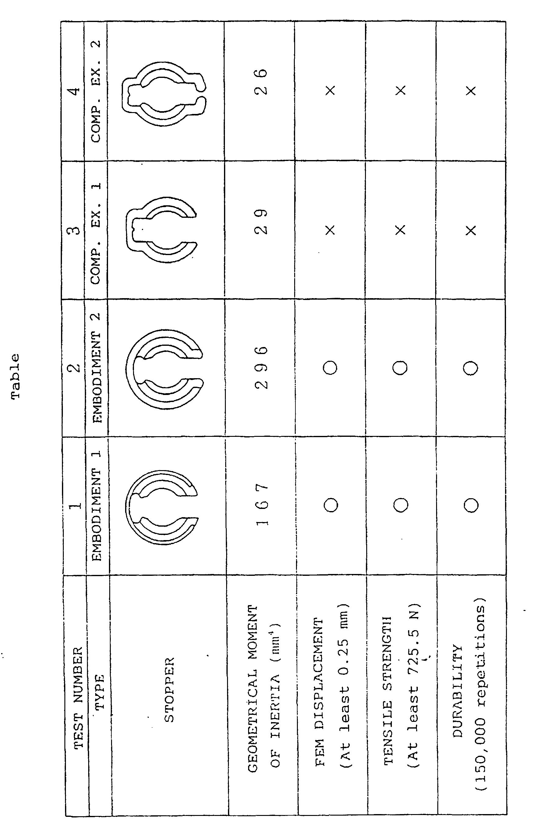
- the stopper 10 of FIG. 1 and the stopper 13 of FIG. 20 for use in the pipe joint of the invention, and stoppers of pipe joints of Comparative Examples 1 and 2 to be described below were tested for geometrical moment of insertia, displacement by the finite element method, tensile strength and durability. These tests will be described below.
- the pipe joint of Comparative Example 1 is a conventional one as previously described.
- the pipe joint of Comparative Example 1 has substantially the same construction except for the stopper which differs from the stoppers 10 and 13 of FIGS. 1 and 20.
- the pipe joint of Comprative Example 2 is another conventional one as previously described.
- the stoppers of Comparative Examples 1 and 2 are both made of nylon 66.
- the geometrical moment of inertia is relative to a widthwise load on the stopper.
- the displacement by the finite element method (FEM displacement) was evaluated as being satisfactory when up to 0.25 mm or as being unacceptable when exceeding 0.25 mm.
- the pipes connected together by the pipe joint to be tested were pulled by a tensile strength tester in directions opposite to each other and checked for the separation of the pipes.
- the tensile strength required of the pipe joints of the type described was evaluated as being satisfactory when not lower than 725.5 N (74 kgf) or as being unacceptable when lower than this value.
- the tests were conducted at a temperature of 120° C to simulate the internal temperature of the engine room of the motor vehicle during driving.
- FIGS. 22 and 23 show a pipe joint of the invention as used for connecting an outlet pipe to the header of a motor vehicle condenser.
- a socket 16 is provided on the header 15 of a condenser 14, a stopper 18 is fitted in apertures 17 of the socket 16, and a spigot 21 having an annular projection 20 is provided on the connection end of an outlet pipe 19.
- the spigot 21 of the outlet pipe 19 is inserted in the socket 16 of the header 15 and fixed thereto by the stopper 18.
- a protrusion 6A is formed externally on the socket 16 for the condenser 14.
- FIGS. 24 and 25 show pipe joints of the invention as used for connecting a liquid inlet pipe and a liquid outlet pipe to the head of a receiver.
- sockets 23a, 23b are provided respectively at a liquid inlet portion and a liquid outlet portion of the head 23 of a receiver 22, a stopper 25 is fitted in apertures 24 of each of the sockets 23a, 23b, spigots 28a, 28b having an annular projection 27a or 27b are provided at the connection ends of a liquid inlet pipe 26a and a liquid outlet pipe 26b, respectively, and the spigots 28a, 28b of the pipes arc inserted in the sockets 23a, 23b on the head 23 and fixed thereto each by the stopper 25.
- a protrusion 23A is formed externally on the sockets 23a, 23b at the inlet and outlet portions.
- a sleeve 25a of smaller width on the stopper 25 does not come into contact with the protrusion 23A of the socket 23a (23b), so that the stopper can be installed in place.
- an assembly error preventing sleeve 25b of the stopper 25 comes into contact with the protrusion 23A of the socket 23a (23b). This prevents the stopper 25 from being mounted as oriented reversely.
- FIG. 26 shows pipe joints of the invention as used for piping for an expansion valve on an evaporator.
- the expansion valve 41 of the block type is provided with two sockets 42a, 42b, and spigots 43a, 43b are provided at the connection ends of two refrigerant transport pipes 46a, 46b to be joined to the sockets 42a, 42b, respectively.
- An inlet pipe 44a and an outlet pipe 44b are connected to the expansion valve 41 by a mount flange 45.
- Indicated at 48 in the drawing is a fastening bolt for the mount flange.
- FIG. 27 shows another embodiment of stopper for use in the pipe joint of the invention.
- the embracing portion 29a of this stopper 29 is C-shaped and has a width larger than the distance L beteeen the two sides of the aperture 5 of the socket 4 which are perpendicular to the axis of the socket.
- the stopper 29 has circular-arc ridges 29b which are formed at one side edge of the embracing portion 29a on its inner surface.
- the stopper 29 has an assembling error preventing sleeve 29c only.
- FIG. 28 shows a protrusion of another type providing an assembly error preventing structure according to the invention.
- a socket 84 has a cylindrical portion 84A of small diameter positioned toward the forward end thereof, and a protrusion 86 in the form of a cylinder of large diameter formed at the base end of the small-diamter cylindrical portion 84A integrally therewith. With the exception of this feature, the structure is the same as in the first embodiment.
- the assembling error preventing structure of this embodiment has the same effect as in the first embodiment.
- the error preventing sleeve of embracing portion of the stoppper comes into contact with the cylindrical protrusion 86 of large diameter provided on the socket 84, preventing mounting of the stopper.
- FIG. 29 shows a protrusion of another type according to the invention.
- a socket 94 formed with apertures 95 is in the form of a cylinder having a uniform diameter in its entirety, and the base end portion of the cylindrical socket 94 is locally provided with a protrusion 96 on the outer surface thereof.
- the structure is the same as in the first embodiment with the exception of this feature.
- the error preventing sleeve of embracing portion of the stopper comes into contact with the local protrusion 96 on the socket 94 as in the foregoing embodiments, preventing mounting of the stopper.
- the local protrusion 96 may alternatively be formed on the outer surface of a forward end portion of the cylindrical socket 94. More specifically stated, the forward end portion of the cylindrical socket 94 beyond its apertures 95 is given a larger length, and the protrusion 96 is formed on this enlarged portion, while the assembling error preventing sleeve of the stopper is provided on the one side thereof opposite to its insertion side for receiving the pipe to be inserted. As a further modification of the present embodiment, the protrusion is provided in the form of a flange at the connection end of the socket in place of a local one.
Landscapes
- Engineering & Computer Science (AREA)
- General Engineering & Computer Science (AREA)
- Mechanical Engineering (AREA)
- Physics & Mathematics (AREA)
- Thermal Sciences (AREA)
- Quick-Acting Or Multi-Walled Pipe Joints (AREA)
- Supports For Pipes And Cables (AREA)
- Joints Allowing Movement (AREA)
- Paper (AREA)
- Non-Disconnectible Joints And Screw-Threaded Joints (AREA)
- Branch Pipes, Bends, And The Like (AREA)
- Protection Of Pipes Against Damage, Friction, And Corrosion (AREA)
Abstract
Description
Claims (6)
- A pipe joint comprising a pipe (11,19,26a,26b,46a,46b) having a spigot (3,21,28a,28b,43a,43b) formed with an annular projection (1,20,27a,27b) on the outer periphery of a base end portion thereof, a stopper (10,10A,13,18,25,29,40) having circular-arc ridges (7a,29b) each formed with a slope (7b) for guiding the annular projection (1,20,27a,27b) of the spigot (3,21,28a,28b,43a,43b) and an engaging face (7d) for enganging the annular projection (1,20,27a,27b), and a socket (4,16,23a,23b,42a,42b,84,94) having apertures (5,17,24,95) for the respective circular-arc ridges (7a,29b) of the stopper (10,10A,13,18,25,29,40) to fit in in an inwardly projecting state, characterized by an assembling error preventing sleeve (10d,18d,25b,29c,40a) formed on the stopper (10,10A,13,18,25,29,40) at one side of the circular-arc ridges (7a,29b) toward the pipe (11,19,26a,26b,46a,46b) to be inserted or at the other side thereof opposite to said side, and a protrusion externally provided on the socket (4,16,23a,23b,42a,42b,84,94) for the error preventing sleeve (10d,18d,25b,29c,40a) of the stopper to come into contact with when the stopper (10,10A,13,18,25,29,40) is to be mounted on the socket (4,16,23a,23b,42a,42b,84,94) with the slopes (7b) of the circular-arc ridges (7a,29b) oriented in a direction opposite to the pipe (11,19,26a,26b,46a,46b) to be inserted.
- A pipe joint as defined in claim 1 wherein the assembling error preventing sleeve (10d,18d,25b,29c,40a) of the stopper (10,10A,18) is C-shaped.
- A pipe joint as defined in claim 1 or 2 wherein the socket (4) has a cylindrical portion (4A) for mounting the stopper (10, 10A) thereon, and the protrusion is a rectangular parallelepiped having a contour larger than the outside diameter of the cylindrical portion (4A).
- A pipe joint as defined in claim 1 or 2 wherein the socket (84) has a cylindrical portion (84A) for mounting the stopper thereon, and the protrusion is a cylindrical portion (86) larger than the cylindrical portion (84A) in outside diameter.
- A pipe joint as defined in claim 1 or 2 wherein the protrusion (96) is locally formed on the outer surface of the socket (94).
- A pipe joint as defined in claim 5 wherein the protrusion (96) is provided on the socket at the pipe insertion side of the apertures (95) or at the opposite side thereof.
Applications Claiming Priority (5)
| Application Number | Priority Date | Filing Date | Title |
|---|---|---|---|
| JP1123395 | 1995-01-27 | ||
| JP1123595 | 1995-01-27 | ||
| JP7011235A JP2733647B2 (en) | 1995-01-27 | 1995-01-27 | Pipe connection device |
| JP7011233A JP2717370B2 (en) | 1995-01-27 | 1995-01-27 | Structure to prevent wrong assembly of stopper in pipe connection device |
| EP95114189A EP0724108B1 (en) | 1995-01-27 | 1995-09-09 | Pipe joint |
Related Parent Applications (1)
| Application Number | Title | Priority Date | Filing Date |
|---|---|---|---|
| EP95114189.4 Division | 1995-09-09 |
Publications (3)
| Publication Number | Publication Date |
|---|---|
| EP0936394A2 EP0936394A2 (en) | 1999-08-18 |
| EP0936394A3 EP0936394A3 (en) | 2000-07-26 |
| EP0936394B1 true EP0936394B1 (en) | 2003-03-12 |
Family
ID=26346649
Family Applications (2)
| Application Number | Title | Priority Date | Filing Date |
|---|---|---|---|
| EP95114189A Expired - Lifetime EP0724108B1 (en) | 1995-01-27 | 1995-09-09 | Pipe joint |
| EP99110419A Expired - Lifetime EP0936394B1 (en) | 1995-01-27 | 1995-09-09 | Pipe joint |
Family Applications Before (1)
| Application Number | Title | Priority Date | Filing Date |
|---|---|---|---|
| EP95114189A Expired - Lifetime EP0724108B1 (en) | 1995-01-27 | 1995-09-09 | Pipe joint |
Country Status (8)
| Country | Link |
|---|---|
| US (1) | US5765877A (en) |
| EP (2) | EP0724108B1 (en) |
| KR (1) | KR100355627B1 (en) |
| AT (2) | ATE191778T1 (en) |
| AU (1) | AU694921B2 (en) |
| DE (2) | DE69529927T2 (en) |
| ES (1) | ES2144552T3 (en) |
| TW (1) | TW347458B (en) |
Families Citing this family (39)
| Publication number | Priority date | Publication date | Assignee | Title |
|---|---|---|---|---|
| US5904221A (en) * | 1994-05-05 | 1999-05-18 | Zf Friedrichshafen Ag | Toothed-rack power-assisted steering in particular for motor vehicles |
| US5803512A (en) * | 1996-03-22 | 1998-09-08 | Hollnagel; Harold E. | Tube quick connect to female socket |
| US6068303A (en) * | 1995-09-13 | 2000-05-30 | Hollnagle; Harold E. | Tube for connection to female socket |
| NL1004679C1 (en) * | 1996-12-03 | 1998-06-05 | Applied Power Inc | Fluid plug-in connection. |
| FR2775507B1 (en) * | 1998-02-27 | 2000-05-19 | Hutchinson | SNAP-ON CONNECTION FOR FLUID CONDUIT, PARTICULARLY FOR MOTOR VEHICLE |
| FR2775509B1 (en) * | 1998-02-27 | 2000-08-11 | Hutchinson | IMPROVEMENT WITH A LOCKABLE CONNECTION FOR A FLUID CONDUIT, PARTICULARLY FOR A MOTOR VEHICLE |
| AT3081U1 (en) * | 1999-04-07 | 1999-09-27 | Hoerbiger Hydraulik | PRESSURE SYSTEM, PRESSURE CYLINDER AND CLAMP |
| DE19932699B4 (en) * | 1999-07-15 | 2005-03-17 | Itw Henschel Gmbh | Fuel rail for an injection gasoline engine |
| US20020071718A1 (en) * | 2000-10-17 | 2002-06-13 | Garry Marty | Retainer clip |
| DE10141315C1 (en) * | 2001-08-28 | 2003-03-20 | Siemens Ag | Coupling for two components through which fluid passes has gripping grooves on outside of jacket which fits partly round first coupling part, leaving assembly aperture |
| US6637779B2 (en) * | 2001-10-18 | 2003-10-28 | Itt Manufacturing Enterprises, Inc. | Fluid quick connector with grooved endform |
| US8113547B2 (en) * | 2002-03-22 | 2012-02-14 | Cooper Standard Automotive Inc. | Snap mount fluid quick connector |
| DE50305324D1 (en) * | 2002-07-03 | 2006-11-23 | Ems Chemie Ag | Quick connection for connecting two pipe ends |
| DE602004030527D1 (en) * | 2003-10-22 | 2011-01-27 | Togo Seisakusho Kk | pipe connection |
| JP4120571B2 (en) * | 2003-11-25 | 2008-07-16 | 株式会社デンソー | Piping joint device |
| JP4196879B2 (en) * | 2004-05-18 | 2008-12-17 | 株式会社デンソー | Piping joint device |
| DE102004038912B3 (en) * | 2004-08-11 | 2005-06-02 | A. Raymond & Cie | Coupling for connecting two components has receiving part and securing part with locking device to ensure proper insertion of insertion part |
| DE102004049847A1 (en) * | 2004-10-13 | 2006-04-20 | John Deere Fabriek Horst B.V. | Head of a spray boom |
| JP4623371B2 (en) | 2005-05-13 | 2011-02-02 | 東海ゴム工業株式会社 | Quick connector |
| DE102005030457A1 (en) * | 2005-06-28 | 2007-01-04 | Mahle International Gmbh | coupling system |
| US8550743B2 (en) * | 2005-09-30 | 2013-10-08 | Medtronic, Inc. | Sliding lock device |
| FR2903164B1 (en) * | 2006-06-30 | 2008-09-26 | Tokai Rubber Ind Ltd | QUICK COUPLING |
| US8048069B2 (en) | 2006-09-29 | 2011-11-01 | Medtronic, Inc. | User interface for ablation therapy |
| JP4345843B2 (en) | 2007-04-27 | 2009-10-14 | 株式会社デンソー | Heat exchanger |
| GB2460641B (en) * | 2008-06-02 | 2013-03-13 | Joy Mm Delaware Inc | A clip for pin retention |
| DE102009036463B4 (en) * | 2009-07-13 | 2023-01-26 | Valeo Klimasysteme Gmbh | Vehicle air conditioning system and method for coupling a tubular element of a vehicle air conditioning system |
| DE102009050076B3 (en) * | 2009-10-20 | 2011-04-07 | A. Kayser Automotive Systems Gmbh | An insertion |
| DE102010033757A1 (en) * | 2010-08-09 | 2012-02-09 | Dbk David + Baader Gmbh | fluid guide |
| TWI414678B (en) * | 2010-10-26 | 2013-11-11 | Kwang Yang Motor Co | The connection structure between the valve element and the intake element of the engine |
| JP6207389B2 (en) * | 2013-12-27 | 2017-10-04 | 株式会社日本クライメイトシステムズ | Drain hose |
| FR3026814B1 (en) * | 2014-10-07 | 2017-04-14 | Caillau Ets | FAST CONNECTION TIP FOR A TUBE |
| US10502353B2 (en) | 2016-05-27 | 2019-12-10 | Kohler Co. | Quick connect release system for a fluid coupling |
| DE102017220448A1 (en) | 2017-11-16 | 2019-05-16 | Mahle International Gmbh | Fluid line coupling with securing clip |
| US10213666B1 (en) | 2018-01-31 | 2019-02-26 | Breakthrough Golf Technology Llc | Golf shaft |
| US10857433B2 (en) | 2018-01-31 | 2020-12-08 | Breakthrough Golf Technology, Llc | Golf shaft system and golf shaft |
| JP6688824B2 (en) | 2018-03-28 | 2020-04-28 | 本田技研工業株式会社 | Structure for preventing misassembly of pipes |
| JP6953472B2 (en) * | 2019-04-26 | 2021-10-27 | Ckd株式会社 | Manifold |
| CN114321096A (en) * | 2021-11-16 | 2022-04-12 | 海洋石油工程股份有限公司 | A quick loading and unloading device for hydraulic test joints for underwater MQC welding and inflation |
| US11850342B2 (en) | 2022-03-21 | 2023-12-26 | Fresenius Medical Care Holdings, Inc. | Securing connections to dialyzers |
Family Cites Families (21)
| Publication number | Priority date | Publication date | Assignee | Title |
|---|---|---|---|---|
| US3314696A (en) * | 1964-02-11 | 1967-04-18 | Perfecting Service Company | Quick connect coupling |
| US3534988A (en) * | 1968-11-15 | 1970-10-20 | Ite Imperial Corp | Tube end mounted sleeve |
| DE2307154A1 (en) * | 1973-02-14 | 1974-08-22 | Daimler Benz Ag | HOSE OR PIPE CONNECTOR |
| JPS586746B2 (en) * | 1974-06-28 | 1983-02-05 | トウヨウインキセイゾウ カブシキガイシヤ | Polyurethane emulsion material |
| US4244608A (en) * | 1979-03-05 | 1981-01-13 | The Gates Rubber Company | Female coupling with staple lock |
| US4423892A (en) * | 1980-10-29 | 1984-01-03 | Bartholomew Donald D | Swivelable quick connector assembly |
| US4524995A (en) * | 1980-10-29 | 1985-06-25 | Proprietary Technology, Inc. | Swivelable quick connector assembly |
| US4601497A (en) * | 1980-10-29 | 1986-07-22 | Proprietary Technology | Swivelable quick connector assembly |
| US4561682A (en) * | 1982-09-03 | 1985-12-31 | Rain Bird Consumer Products Mfg. Corp. | Quick connect coupling |
| US4691943A (en) * | 1985-04-24 | 1987-09-08 | Schmelzer Corporation | Quick connect fluid fitting assembly |
| JPH01206197A (en) * | 1988-02-12 | 1989-08-18 | Nitta Mua Co:Kk | Tube joint |
| US4875709A (en) * | 1988-02-26 | 1989-10-24 | Caroll James E | Controlled leak path |
| US4889368A (en) * | 1988-12-12 | 1989-12-26 | Aeroquip Corporation | Combination quick-connect and thread-disconnect tube connector |
| JPH03219189A (en) * | 1990-01-22 | 1991-09-26 | Usui Internatl Ind Co Ltd | Connector for jointing small bore pipes |
| KR930003237B1 (en) | 1990-06-27 | 1993-04-23 | 현대전자산업 주식회사 | Undershoot resistor circuit |
| US5211427A (en) * | 1990-12-22 | 1993-05-18 | Usui Kokusai Sangyo Kaisha Ltd. | Piping connector |
| JP3071498B2 (en) * | 1991-05-30 | 2000-07-31 | 臼井国際産業株式会社 | Piping connector |
| JPH0522985U (en) * | 1991-09-05 | 1993-03-26 | 鈴木 茂 | Pipe connector |
| JPH0653591A (en) | 1992-08-03 | 1994-02-25 | Nippon Telegr & Teleph Corp <Ntt> | Optical frequency conversion element |
| KR100267605B1 (en) * | 1992-09-24 | 2000-10-16 | 안자이 이치로 | Pipe joint |
| ES2155548T3 (en) * | 1995-05-17 | 2001-05-16 | Showa Aluminum Corp | CONNECTION FOR TUBES. |
-
1995
- 1995-06-07 US US08/488,022 patent/US5765877A/en not_active Expired - Lifetime
- 1995-09-02 TW TW084109195A patent/TW347458B/en active
- 1995-09-08 AU AU30543/95A patent/AU694921B2/en not_active Ceased
- 1995-09-09 AT AT95114189T patent/ATE191778T1/en not_active IP Right Cessation
- 1995-09-09 EP EP95114189A patent/EP0724108B1/en not_active Expired - Lifetime
- 1995-09-09 DE DE69529927T patent/DE69529927T2/en not_active Expired - Fee Related
- 1995-09-09 AT AT99110419T patent/ATE234440T1/en not_active IP Right Cessation
- 1995-09-09 DE DE69516261T patent/DE69516261T2/en not_active Expired - Lifetime
- 1995-09-09 ES ES95114189T patent/ES2144552T3/en not_active Expired - Lifetime
- 1995-09-09 EP EP99110419A patent/EP0936394B1/en not_active Expired - Lifetime
- 1995-09-28 KR KR1019950032290A patent/KR100355627B1/en not_active Expired - Fee Related
Also Published As
| Publication number | Publication date |
|---|---|
| EP0724108B1 (en) | 2000-04-12 |
| KR100355627B1 (en) | 2002-12-11 |
| ATE234440T1 (en) | 2003-03-15 |
| DE69529927D1 (en) | 2003-04-17 |
| DE69529927T2 (en) | 2003-12-11 |
| DE69516261D1 (en) | 2000-05-18 |
| EP0936394A3 (en) | 2000-07-26 |
| US5765877A (en) | 1998-06-16 |
| EP0724108A1 (en) | 1996-07-31 |
| DE69516261T2 (en) | 2000-08-10 |
| TW347458B (en) | 1998-12-11 |
| AU694921B2 (en) | 1998-08-06 |
| ATE191778T1 (en) | 2000-04-15 |
| KR960029688A (en) | 1996-08-17 |
| AU3054395A (en) | 1996-08-08 |
| ES2144552T3 (en) | 2000-06-16 |
| EP0936394A2 (en) | 1999-08-18 |
Similar Documents
| Publication | Publication Date | Title |
|---|---|---|
| EP0724108B1 (en) | Pipe joint | |
| US5395140A (en) | Secondary latch and indicator for fluid coupling | |
| EP0593937A1 (en) | Pipe joint | |
| US4979765A (en) | Swivelable quick connector assembly | |
| US7810848B2 (en) | Pipe joint and pipe joint structure having the same and method of using the same | |
| US4565392A (en) | Quick connect coupling | |
| US5195787A (en) | Quick connector with heavy-duty retainer | |
| EP0529758A1 (en) | Quick connect coupling | |
| JP2002525542A (en) | Clip fittings for hoses | |
| JP2002276878A (en) | Piping fittings | |
| WO1994008172A1 (en) | Positive transition quick connect coupling | |
| JP2002206683A (en) | Piping fittings | |
| GB2290591A (en) | End fitting for pipe connection | |
| JPH04211791A (en) | Joint coupling insert type tube and method thereof | |
| US7104571B2 (en) | Connector clip for verifying complete connection between a connector and a pipe | |
| US6601878B2 (en) | Connector assemblies suitable for attachment to bent tubular conduit | |
| KR100403524B1 (en) | Steckkupplung mit zwei zusammensteckbaren rohrformigen kupplungsteilen | |
| US5655796A (en) | Tubular assembly and method of making same | |
| US20240174284A1 (en) | Steering shaft with alignment mechanism disposed in an end thereof to facilitate aligned fixation with a clamp yoke | |
| WO1998028566A1 (en) | One piece quick connector and integral retainer | |
| EP0660907B1 (en) | Tubular assembly and method of making same | |
| US6290264B1 (en) | Piping structure | |
| JPH08200577A (en) | Pipe connection device | |
| JP2717370B2 (en) | Structure to prevent wrong assembly of stopper in pipe connection device | |
| KR102225479B1 (en) | Air conditioning fitting with axial and radial elastomeric sealing element and metal to metal taper saddle |
Legal Events
| Date | Code | Title | Description |
|---|---|---|---|
| PUAI | Public reference made under article 153(3) epc to a published international application that has entered the european phase |
Free format text: ORIGINAL CODE: 0009012 |
|
| 17P | Request for examination filed |
Effective date: 19990528 |
|
| AC | Divisional application: reference to earlier application |
Ref document number: 724108 Country of ref document: EP |
|
| AK | Designated contracting states |
Kind code of ref document: A2 Designated state(s): AT CH DE ES FR GB IT LI SE |
|
| PUAL | Search report despatched |
Free format text: ORIGINAL CODE: 0009013 |
|
| AK | Designated contracting states |
Kind code of ref document: A3 Designated state(s): AT CH DE ES FR GB IT LI SE |
|
| RIC1 | Information provided on ipc code assigned before grant |
Free format text: 7F 16L 37/12 A, 7F 16L 37/088 B |
|
| 17Q | First examination report despatched |
Effective date: 20010112 |
|
| RAP1 | Party data changed (applicant data changed or rights of an application transferred) |
Owner name: SHOWA DENKO K K |
|
| RAP1 | Party data changed (applicant data changed or rights of an application transferred) |
Owner name: SHOWA DENKO K.K. |
|
| GRAG | Despatch of communication of intention to grant |
Free format text: ORIGINAL CODE: EPIDOS AGRA |
|
| GRAG | Despatch of communication of intention to grant |
Free format text: ORIGINAL CODE: EPIDOS AGRA |
|
| GRAG | Despatch of communication of intention to grant |
Free format text: ORIGINAL CODE: EPIDOS AGRA |
|
| GRAG | Despatch of communication of intention to grant |
Free format text: ORIGINAL CODE: EPIDOS AGRA |
|
| GRAG | Despatch of communication of intention to grant |
Free format text: ORIGINAL CODE: EPIDOS AGRA |
|
| GRAH | Despatch of communication of intention to grant a patent |
Free format text: ORIGINAL CODE: EPIDOS IGRA |
|
| GRAH | Despatch of communication of intention to grant a patent |
Free format text: ORIGINAL CODE: EPIDOS IGRA |
|
| GRAA | (expected) grant |
Free format text: ORIGINAL CODE: 0009210 |
|
| AC | Divisional application: reference to earlier application |
Ref document number: 0724108 Country of ref document: EP Kind code of ref document: P |
|
| AK | Designated contracting states |
Designated state(s): AT CH DE ES FR GB IT LI SE |
|
| PG25 | Lapsed in a contracting state [announced via postgrant information from national office to epo] |
Ref country code: LI Free format text: LAPSE BECAUSE OF FAILURE TO SUBMIT A TRANSLATION OF THE DESCRIPTION OR TO PAY THE FEE WITHIN THE PRESCRIBED TIME-LIMIT Effective date: 20030312 Ref country code: CH Free format text: LAPSE BECAUSE OF FAILURE TO SUBMIT A TRANSLATION OF THE DESCRIPTION OR TO PAY THE FEE WITHIN THE PRESCRIBED TIME-LIMIT Effective date: 20030312 Ref country code: AT Free format text: LAPSE BECAUSE OF FAILURE TO SUBMIT A TRANSLATION OF THE DESCRIPTION OR TO PAY THE FEE WITHIN THE PRESCRIBED TIME-LIMIT Effective date: 20030312 |
|
| REG | Reference to a national code |
Ref country code: GB Ref legal event code: FG4D |
|
| REG | Reference to a national code |
Ref country code: CH Ref legal event code: EP |
|
| REF | Corresponds to: |
Ref document number: 69529927 Country of ref document: DE Date of ref document: 20030417 Kind code of ref document: P |
|
| PGFP | Annual fee paid to national office [announced via postgrant information from national office to epo] |
Ref country code: GB Payment date: 20030902 Year of fee payment: 9 |
|
| REG | Reference to a national code |
Ref country code: CH Ref legal event code: PL |
|
| PGFP | Annual fee paid to national office [announced via postgrant information from national office to epo] |
Ref country code: SE Payment date: 20030916 Year of fee payment: 9 |
|
| PGFP | Annual fee paid to national office [announced via postgrant information from national office to epo] |
Ref country code: FR Payment date: 20030929 Year of fee payment: 9 |
|
| PG25 | Lapsed in a contracting state [announced via postgrant information from national office to epo] |
Ref country code: ES Free format text: LAPSE BECAUSE OF FAILURE TO SUBMIT A TRANSLATION OF THE DESCRIPTION OR TO PAY THE FEE WITHIN THE PRESCRIBED TIME-LIMIT Effective date: 20030930 |
|
| PGFP | Annual fee paid to national office [announced via postgrant information from national office to epo] |
Ref country code: DE Payment date: 20030930 Year of fee payment: 9 |
|
| ET | Fr: translation filed | ||
| PLBE | No opposition filed within time limit |
Free format text: ORIGINAL CODE: 0009261 |
|
| STAA | Information on the status of an ep patent application or granted ep patent |
Free format text: STATUS: NO OPPOSITION FILED WITHIN TIME LIMIT |
|
| 26N | No opposition filed |
Effective date: 20031215 |
|
| PG25 | Lapsed in a contracting state [announced via postgrant information from national office to epo] |
Ref country code: GB Free format text: LAPSE BECAUSE OF NON-PAYMENT OF DUE FEES Effective date: 20040909 |
|
| PG25 | Lapsed in a contracting state [announced via postgrant information from national office to epo] |
Ref country code: SE Free format text: LAPSE BECAUSE OF NON-PAYMENT OF DUE FEES Effective date: 20040910 |
|
| PG25 | Lapsed in a contracting state [announced via postgrant information from national office to epo] |
Ref country code: DE Free format text: LAPSE BECAUSE OF NON-PAYMENT OF DUE FEES Effective date: 20050401 |
|
| GBPC | Gb: european patent ceased through non-payment of renewal fee |
Effective date: 20040909 |
|
| EUG | Se: european patent has lapsed | ||
| PG25 | Lapsed in a contracting state [announced via postgrant information from national office to epo] |
Ref country code: FR Free format text: LAPSE BECAUSE OF NON-PAYMENT OF DUE FEES Effective date: 20050531 |
|
| REG | Reference to a national code |
Ref country code: FR Ref legal event code: ST |
|
| PG25 | Lapsed in a contracting state [announced via postgrant information from national office to epo] |
Ref country code: IT Free format text: LAPSE BECAUSE OF NON-PAYMENT OF DUE FEES Effective date: 20050909 |