EP0935835B1 - Auxiliary battery sensor switch - Google Patents
Auxiliary battery sensor switch Download PDFInfo
- Publication number
- EP0935835B1 EP0935835B1 EP97946321A EP97946321A EP0935835B1 EP 0935835 B1 EP0935835 B1 EP 0935835B1 EP 97946321 A EP97946321 A EP 97946321A EP 97946321 A EP97946321 A EP 97946321A EP 0935835 B1 EP0935835 B1 EP 0935835B1
- Authority
- EP
- European Patent Office
- Prior art keywords
- battery
- voltage
- current
- resistor
- signal
- Prior art date
- Legal status (The legal status is an assumption and is not a legal conclusion. Google has not performed a legal analysis and makes no representation as to the accuracy of the status listed.)
- Expired - Lifetime
Links
Images


Classifications
-
- H—ELECTRICITY
- H02—GENERATION; CONVERSION OR DISTRIBUTION OF ELECTRIC POWER
- H02J—ELECTRIC POWER NETWORKS; CIRCUIT ARRANGEMENTS OR SYSTEMS FOR SUPPLYING OR DISTRIBUTING ELECTRIC POWER; SYSTEMS FOR STORING ELECTRIC ENERGY
- H02J7/00—Circuit arrangements for charging or discharging batteries or for supplying loads from batteries
- H02J7/34—Parallel operation in networks using both storage and other DC sources, e.g. providing buffering
- H02J7/342—The other DC source being a battery actively interacting with the first one, i.e. battery to battery charging
-
- H—ELECTRICITY
- H02—GENERATION; CONVERSION OR DISTRIBUTION OF ELECTRIC POWER
- H02J—ELECTRIC POWER NETWORKS; CIRCUIT ARRANGEMENTS OR SYSTEMS FOR SUPPLYING OR DISTRIBUTING ELECTRIC POWER; SYSTEMS FOR STORING ELECTRIC ENERGY
- H02J7/00—Circuit arrangements for charging or discharging batteries or for supplying loads from batteries
- H02J7/50—Circuit arrangements for charging or discharging batteries or for supplying loads from batteries acting upon multiple batteries simultaneously or sequentially
- H02J7/575—Parallel/serial switching of connection of batteries to charge or load circuit
-
- H—ELECTRICITY
- H02—GENERATION; CONVERSION OR DISTRIBUTION OF ELECTRIC POWER
- H02J—ELECTRIC POWER NETWORKS; CIRCUIT ARRANGEMENTS OR SYSTEMS FOR SUPPLYING OR DISTRIBUTING ELECTRIC POWER; SYSTEMS FOR STORING ELECTRIC ENERGY
- H02J7/00—Circuit arrangements for charging or discharging batteries or for supplying loads from batteries
- H02J7/60—Circuit arrangements for charging or discharging batteries or for supplying loads from batteries including safety or protection arrangements
- H02J7/685—Circuit arrangements for charging or discharging batteries or for supplying loads from batteries including safety or protection arrangements using connection detecting circuits
-
- H—ELECTRICITY
- H02—GENERATION; CONVERSION OR DISTRIBUTION OF ELECTRIC POWER
- H02J—ELECTRIC POWER NETWORKS; CIRCUIT ARRANGEMENTS OR SYSTEMS FOR SUPPLYING OR DISTRIBUTING ELECTRIC POWER; SYSTEMS FOR STORING ELECTRIC ENERGY
- H02J7/00—Circuit arrangements for charging or discharging batteries or for supplying loads from batteries
- H02J7/70—Circuit arrangements for charging or discharging batteries or for supplying loads from batteries characterised by the mechanical construction
- H02J7/731—Circuit arrangements for charging or discharging batteries or for supplying loads from batteries characterised by the mechanical construction specially adapted for holding portable devices containing batteries
-
- H—ELECTRICITY
- H04—ELECTRIC COMMUNICATION TECHNIQUE
- H04B—TRANSMISSION
- H04B1/00—Details of transmission systems, not covered by a single one of groups H04B3/00 - H04B13/00; Details of transmission systems not characterised by the medium used for transmission
- H04B1/38—Transceivers, i.e. devices in which transmitter and receiver form a structural unit and in which at least one part is used for functions of transmitting and receiving
- H04B1/3827—Portable transceivers
- H04B1/385—Transceivers carried on the body, e.g. in helmets
- H04B2001/3855—Transceivers carried on the body, e.g. in helmets carried in a belt or harness
Definitions
- the present invention relates generally to means for extending the battery life of portable electronic devices such as cellular telephones, and more particularly, to a switch capable of sensing the presence of an auxiliary battery and switching the power circuitry of the electronic device to the auxiliary battery.
- the battery pack is the main power source for portable electronic devices such as cellular phones.
- portable nature of cellular phones are limited by the fact that their battery power will not last forever. After a period of time the batteries become discharged and the cellular phone must be plugged into a charger in order to recharge the battery. In order to achieve more battery power (longer battery life), typically the size of the battery cell must be increased. This presents a problem for cellular telephone designers due to the conflicts between a desire for longer talk time and standby for the phone (i.e., longer battery life) and the desire for smaller, lighter telephones.
- the present invention overcomes the foregoing and other problems with an apparatus for switching between a main and an auxiliary battery in response to connection of the auxiliary battery to an electronic device such as a portable communications device.
- the main and auxiliary batteries are connected to system power through first and second switches respectively.
- the main battery is located within the cellular telephone unit but is only connected to system power when the auxiliary battery is not connected or the auxiliary battery's voltage falls below a particular level.
- the auxiliary battery is connected to the belt holder for the cellular telephone.
- the first and second switches are controlled by control signals from a microprocessor.
- connection of the auxiliary battery creates a current through the switching circuitry which is detected by a current sensor.
- the current sensor generates a current signal in response to the current flow and provides this signal to the microprocessor.
- a voltage sensor measures the voltage level present within the auxiliary battery to determine if the voltage level meets a predetermined threshold voltage. The voltage sensor then generates a voltage signal indicating whether or not the voltage level meets the desired threshold and provides this signal to the microprocessor.
- connection of the auxiliary battery generates a voltage across a resistor in the switching circuitry which is detected by a voltage sensor.
- the voltage sensor generates a signal in response to the voltage across the resistor and provides this to the microprocessor.
- the voltage sensor In response to detection of the voltage, the voltage sensor also measures the voltage level present within the auxiliary battery to assist in determining if the voltage level meets a predetermined threshold level.
- the microprocessor utilizes the current signal and/or voltage signal to determine which battery to connect to system power. If the signals indicate the auxiliary battery is not connected, the main battery is connected. If the signals indicate the auxiliary battery is connected but the auxiliary battery does not contain sufficient voltage, the main battery is connected and the auxiliary battery is disconnected. However, if the auxiliary battery is connected and contains a sufficient voltage level, the auxiliary battery is connected while the main battery is disconnected. In this manner the effective battery life of the main battery is extended without corresponding increases in the size of the battery supply associated with the cellular telephone unit.
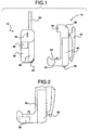
- FIGURE 1 there is illustrated a side view of a cellular telephone holder 15 incorporating an auxiliary battery and an associated cellular telephone unit 10.
- the cellular telephone unit 10 includes the main housing 20, a battery 25 and antenna 30.
- Contact 35 at the base of the cellular telephone provides a connection to the power circuitry of the cellular telephone unit 10.
- the circuitry interconnected with the contact 35 will be more fully discussed in a moment. While the present description illustrates the contact being placed at the base of the cellular telephone unit 10, the contact may of course be located at any point enabling interconnection of the cellular telephone unit 10 with the auxiliary battery 40 of the telephone holder 15.
- the cellular telephone holder 15 includes the auxiliary battery 40 integrally connected with a housing 55.
- the holder housing 55 is designed such that it is integrated with auxiliary battery 40 as a single piece or such that the auxiliary battery may be removably connected to the holder housing by sliding, snapping or some other type of connection means.
- the cellular telephone holder 15 may also include a charger connection 49 for connecting a battery recharger.
- the housing 55 defines a cradle 53 for holding the cellular telephone unit 10.
- a holding rib 56 in the housing 55 may be positioned to lockably engage a corresponding slot 60 within the housing 20 of the cellular telephone unit 10.
- the rib 56 and slot 60 combination secure the telephone unit 10 within the cradle 53 while still enabling removal of the telephone unit from the telephone holder 15.
- the cradle 53 for the cellular telephone unit 10 further includes a contact 70 for engaging the contact 35 of the portable telephone unit 10.
- the contact 70 interconnects the positive and negative terminals of the auxiliary battery 40 to the portable telephone unit 10.
- auxiliary battery sensor circuitry 80 Internal to the portable telephone unit 10 is auxiliary battery sensor circuitry 80 for switching system power between the main 25 and the auxiliary 40 batteries. Switching between the batteries is responsive to changes in current initiated by placement or removal of the telephone unit 10 from the housing 55. The sensor 80 also switches power back to the main battery 25 should the charge of the auxiliary battery 40 become depleted. The preferred embodiment of the sensor circuitry 80 will be more fully discussed with respect to FIGURES 3-5.
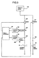
- FIGURE 2 there is illustrated a side view of an alternative embodiment of the cellular telephone holder 55 wherein there is included within the cradle, an opening 85 enabling the attachment of peripheral devices to the telephone unit 10. Through this opening 85 data accessories, chargers, and/or alternative telephone connections may be connected to the telephone unit 10.
- FIGURES 1-2 have been described with respect to the use of a cellular telephone and cellular telephone holder, the use of the electronic holding device having an integrated auxiliary battery would be equally applicable to any electronic device having a standby mode and an internal battery or a need to increase battery life.
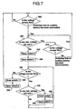
- auxiliary battery sensor circuitry 80 for detecting the connection of a auxiliary battery 40 to the cellular telephone unit 10.
- the sensor circuitry 80 incudes a pair of connections 100 for interconnecting the main battery 25 and auxiliary battery 40 to the power circuitry of the telephone unit 10.
- a pair of switches 115 and 120 interconnect the main 25 and auxiliary 40 batteries to the remainder of the telephone power circuitry 118.
- the switches 120 and 115 are controlled by a microprocessor 125 in response to control signals received from a current sensor 130 and a voltage sensor 135.
- the current sensor 130 detects current passing through a resistor 150. Current flow through the resistor 150 is initiated by connection of the auxiliary battery 40 to the portable telephone unit 10. Referring now also to FIGURE 4 wherein there is illustrated the circuitry of the current sensor 130. Voltage readings (V 1 and V 2 ) are taken from each end of the resistor 150 and applied to the inputs of a pair of operational amplifiers 155. The voltage V 1 is connected to the positive input of operational amplifier 155a while voltage V 2 is connected to the negative input. The inputs of the operational amplifier 155b are connected to the voltages in the opposite manner. The operational amplifiers 155 amplify the difference in voltage across the resistor 155. Since a negative supply voltage is not available within the portable telephone unit 10, each operational amplifier 155 has its negative supply 162 grounded and cannot supply a negative voltage. Consequently, two operational amplifiers 155 are needed to amplify the differential voltage for each direction of current flow.
- each operational amplifier 155 The voltage differential output of each operational amplifier 155 is provided to the inputs-of an OR gate 170. If either the first or second operational amplifier 155 generates a high voltage, indicating current is flowing through the sensor resistor 150, the OR gate 170 outputs a logical high voltage signal. This is interpreted by the microprocessor 125 as connection of a auxiliary battery and switch 120 is closed while switch 115 is opened to preserve power to the main battery 25. When the output of both the first and second operational amplifiers 155 are low, OR gate 170 generates a logical low voltage signal, and switch 115 is closed to provide power from the main battery 25. Switch 120 also remains closed to enable current flow to occur through resistor 150 once an auxiliary battery 40 is connected.
- the voltage sensor 135 determines the voltage output of a connected auxiliary battery 40 and generates a voltage signal indicating whether sufficient voltage exists to power the cellular telephone unit 10. Sufficient voltage is based upon whether the auxiliary battery 40 can supply a pre-selected threshold voltage. When the auxiliary battery voltage falls below the predetermined threshold, a signal is generated indicating this to the microprocessor 125. Switch 120 then opens to disconnect the auxiliary battery 40 from the power circuitry 118, and switch 115 closes to connect the main battery 25. With switch 120 open resistor 150 can no longer detect connection of the auxiliary battery 40. Therefore, a resistor 200 enables detection of a physical connection of the auxiliary battery 40 to connection 100. When the auxiliary battery 40 engages connector 100, the voltage across resistor 200 will be positive. Once the auxiliary battery 40 is disconnected, the voltage across resistor 200 goes to zero. The voltage across resistor 200 is monitored by the voltage sensor 135.
- FIGURE 5 there is illustrated a flow diagram describing the algorithm for controlling switches 115 and 120 by the microprocessor 125.
- This algorithm outlines the decision processes followed by the microprocessor 125. Initially, both switches 115 and 120 are closed.
- Inquiry step 210 determines whether an auxiliary battery 40 has been connected to the cellular telephone unit 10 by measuring current through resistor 150. The microprocessor 125 continues to monitor for connection of the auxiliary battery 40 at step 210 until a connection is detected. Once an auxiliary battery 40 connection is detected, inquiry step 215 determines if the auxiliary battery voltage is too low. When the voltage level is to low, switch 120 is opened at step 220. Inquiry step 221 determines whether the voltage across resistor 200 is greater than zero.
- a voltage across resistor 200 of greater than zero indicates that the auxiliary battery remains connected. If the auxiliary battery 40 is connected, control passes back to step 215 to determine whether or not the battery voltage is too low. If the auxiliary battery 40 is disconnected, switch 120 is closed at step 222 and control passes back to step 210 to monitor for a re-connection of the auxiliary battery.
- switch 115 is opened at step 225.
- Inquiry step 230 determines whether the auxiliary battery 40 is still connected by sensing current through resistor 200. If the auxiliary battery 40 remains connected, inquiry step 235 determines if sufficient auxiliary battery voltage still remains. As long as the auxiliary battery 40 remains connected and provides -sufficient voltage, control continues to loop through inquiry steps 230 and 235 to monitor for auxiliary battery 40 disconnection and low voltages. Should the voltage within the auxiliary battery 40 drop below acceptable levels, switch 120 is opened at step 240 while switch 115 is closed at step 245 to connect the telephone unit 10 to the main battery 25.
- inquiry step 246 determines whether the auxiliary battery 40 is still connected by determining whether the voltage across resistor 100 is greater than zero. If so, control passes back to step 235 to determine whether or not the auxiliary battery voltage is still to low. If the auxiliary battery has been disconnected, control passes to steps 250 and 255 to reset switches 120 and 115 to await reconnection of the auxiliary battery 40.
- switch 115 is closed at step 250 while switch 120 is closed at step 255. This passes control of system power to the main battery 25 and control returns back to step 210 to wait for reconnection of the auxiliary battery 40.
- the apparatus will operate in the following manner.
- the auxiliary battery 40 is not connected, and the power source for the telephone unit 10 is the main battery 25.
- Switch 115 is closed so that the phone draws current from the main battery 25.
- Switch 120 also remains closed to enable detection of the connection of an auxiliary battery 40.
- a user connects the auxiliary battery 40, current passes through the sensor resistor 150 and voltage across resistor 200 becomes greater than zero. This current flow is detected by the current sensor 130 and a current signal notifying the microprocessor 125 is generated.
- the voltage sensor 135 and microprocessor 125 determine if sufficient voltage exists to operate the phone unit 10. If the voltage of the auxiliary battery 40 is too low, the microprocessor 125 keeps switch 115 closed and opens switch 120. This prevents the auxiliary battery 40 from draining current from the main battery 25. If the voltage is sufficient, the microprocessor 125 opens switch 115 to prevent further current drain from the main battery 25.
- Switch 115 remains opened and switch 120 closed until such time as the voltage of the auxiliary battery 40 drops below the preselected threshold level, or the telephone unit 10 is disconnected from the auxiliary battery. In either case, switch 115 is closed so that the telephone unit 10 is now powered by the main battery 25. If switch 115 is closed due to low voltage level switch 120 is opened for the reasons discussed above. If the auxiliary battery 40 has been disconnected as indicated by the voltage across resistor 200, switch 120 remains closed to enable detection of current flow to the sensor resistor 150.
- circuitry has been described with respect to a cellular telephone unit. However, it should be realized that the circuitry is applicable to other electronic devices requiring increased battery times without an associated increase in device size.
- FIGURE 6 there is illustrated an alternative embodiment of the present invention wherein only a voltage sensor 135 monitors for connection of the auxiliary battery 40. Similar reference numerals are used for common parts as those described in FIGURE 3.
- the sensor circuitry 80 includes a pair of connections 100 for interconnecting the main battery 25 and auxiliary battery 40 to the power circuitry 118 of the telephone unit 10.
- a pair of switches 115 and 120 interconnect the main 25 and auxiliary 40 batteries to the remainder of the telephone power circuitry 118.
- the switches 120 and 115 are controlled by a microprocessor 125 in response to control signals received from a voltage sensor 135.
- the voltage sensor 135 monitors the voltage across a resistor 200.
- the voltage across resistor 200 changes in response to connection of the auxiliary battery 40 to connector 100 of the sensor circuitry 80. When the auxiliary battery 40 engages connector 100, the voltage across resistor 200 will be positive. Once the auxiliary battery 40 is disconnected, the voltage across resistor 200 goes to zero if switch 120 is open.
- the voltage sensor 135 also monitors the voltage output of the connected auxiliary battery 40 and generates a signal indicating whether sufficient voltage exists to power the cellular telephone unit 10. Sufficient voltage is based upon whether the auxiliary battery 40 can supply a preselected threshold voltage. When the auxiliary battery voltage falls below the predetermined threshold, a signal is generated indicating this to the microprocessor 125. The auxiliary battery is then disconnected from the circuit.
- FIGURE 7 there is illustrated a flow diagram describing the algorithm for controlling switches 115 and 120 by the microprocessor 125 for the embodiment of FIGURE 6.
- the algorithm outlines the decision processes followed by the microprocessor 125.
- switch 115 is closed while switch 120 is opened. This connects the main battery 25 to the telephone power circuitry 118.
- Inquiry step 300 monitors the voltage across resistor 200 to determine whether or not the voltage is greater than zero. A voltage level of zero indicates that the auxiliary battery 40 has not been connected and control continues to loop through step 300.
- inquiry step 305 determines whether the auxiliary battery voltage is too low. If so, control passes to inquiry step 310 to again determine if the voltage across resistor 200 is greater than zero. If so, control continues to return to step 305. Once the voltage across resistor 200 indicates the auxiliary battery 40 has been disconnected, control passes back to step 300.
- inquiry step 305 determines the auxiliary battery voltage is not too low
- switch 120 is closed at step 315 and switch 115 is opened at step 320. This disconnects the main battery 25 from the power circuitry 118 and connects the auxiliary battery 40.
- the voltage sensor 135 continues to monitor for the connection of the auxiliary battery 40 to the power circuitry 118 at inquiry step 325. If the resistor 200 maintains a positive voltage, inquiry step 330 again checks whether the auxiliary battery voltage is too low. If so, switch 115 is closed at step 335 and switch 120 is opened at step 340 to disconnect the auxiliary battery 40 from the power circuitry 118 and control returns to step 325. If the voltage is not too low, the processor 125 merely continues to monitor for continued connection by returning to step 325.
- step 325 determines the voltage across resistor 200 is no longer greater than zero
- switch 115 is closed at step 345 and switch 120 is opened at step 350 to reconnect the main battery 25.
- Control then returns to step 300 to monitor for reconnection of an auxiliary battery 40.
- the alternative embodiment will operate in the following manner. In the normal mode of operation, the auxiliary battery 40 is not connected, and the source of power for the cellular telephone unit 10 is the main battery 25. Thus, in normal operation, switch 115 is closed so that the cellular telephone unit 10 can draw current from the main battery 25. Switch 120 is opened during normal operation. The cellular telephone unit microprocessor 125 continually monitors the voltage sensor 135 to determine the voltage across resistor 200.
- auxiliary battery 40 When an auxiliary battery 40 is connected, a voltage drop is created across resistor 200 and the voltage of the auxiliary battery 40 can be read through voltage sensor 135.
- the microprocessor 125 determines if the auxiliary battery 40 has sufficient voltage to operate the cellular telephone unit 10. If the voltage of the auxiliary battery 40 is too low to operate the cellular telephone unit 10, the microprocessor 125 will do nothing and the phone will continue to be powered by the main battery 25. If the voltage of the auxiliary battery 40 is high enough, the microprocessor 125 will close switch 120, enabling the cellular telephone unit 10 to draw current from the auxiliary battery 40. The cellular telephone unit 10 will then open switch 115 thereby preventing any further current drain from the main battery 25.
- the cellular telephone unit 10 will keep switch 115 opened and switch 120 closed until such time as the microprocessor 125 detects either the voltage of the auxiliary battery 40 falling below the minimum threshold level, or that the cellular telephone unit 10 has been disconnected from the auxiliary battery 40. In either case, once this is detected, switch 115 closes so that the telephone can be powered by main battery 25. Switch 120 is opened to facilitate future detection of an auxiliary battery 40 with sufficient voltage to power the telephone.
Landscapes
- Engineering & Computer Science (AREA)
- Power Engineering (AREA)
- Mobile Radio Communication Systems (AREA)
- Charge And Discharge Circuits For Batteries Or The Like (AREA)
- Telephone Function (AREA)
- Battery Mounting, Suspending (AREA)
- Air Bags (AREA)
- Burglar Alarm Systems (AREA)
- Electrophonic Musical Instruments (AREA)
Description
Claims (22)
- An apparatus for switching between a first battery (25) and a removable second battery (40) in an electronic device, characterised by:means (1,2) for interconnecting the first battery and the second battery to a power system of the electronic device,means (130,135) for sensing a voltage/current condition change initiated by connection of the removable second battery to the electronic device and for generating a change signal indicating a presence of the removable second battery, anda processor (125), responsive to the change signal generated by the means for sensing, for instructing the means for interconnecting to connect the second battery to system power and disconnect the first battery from system power.
- The apparatus of claim 1, wherein the means for interconnecting comprises first and second switches, associated with the first and the second batteries respectively, for interconnecting the first battery and the second battery to power circuitry of the electronic device.
- The apparatus of claim 1 wherein the electronic device comprises a portable communication device.
- The apparatus of claim 1, wherein the means for sensing comprises a current sensing circuit for detecting a current flow initiated by connection of the second battery and generating a current signal indicative thereof, and
a voltage sensing circuit for determining if the second battery provides a preselected voltage level and generating a voltage signal indicative thereof,
wherein the processor connects and disconnects the first battery and the second battery in response to the voltage signal and the current signal. - The apparatus of claim 4 wherein the current sensing circuit comprises a resistor connected to the portable communications device through which current flows in response to connection of the second battery, and
a current sensor for generating the current signal in response to current flow through the resistor. - The apparatus of claim 5 wherein the current sensor comprises:first and second operational amplifiers for measuring the differential voltage across the resistor, andan OR gate responsive to the outputs of the first and second operational amplifiers for generating the current signal indicating the current flow in the resistor.
- The apparatus of claim 6 wherein a negative voltage supply of the first and second operational amplifiers is grounded.
- The apparatus of claim 4 wherein the processor disconnects the first battery and connects the second battery upon indication of current flow by the current signal.
- The apparatus of claim 4 wherein the processor connects the first battery and disconnects the second battery upon indication of no current flow by the current signal.
- The apparatus of claim 4 wherein the processor disconnects the second battery and connects the first battery when the voltage signal indicates a second battery voltage below the preselected voltage level.
- The apparatus of claim 1 wherein the means for sensing comprises:a resistor; andmeans for sensing a voltage change across the resistor initiated by connection of the removable second battery to the electronic device and for generating the change signal indicating a presence of the voltage change.
- The apparatus of claim 1 wherein the means for sensing comprises:wherein the processor connects and disconnects the first battery and the second battery in response to the first and second voltage signals.a voltage sensor for generating a first voltage signal in response to a voltage drop, said voltage sensor further determining if the second battery provides a preselected voltage level in generating a second voltage signal indicative thereof;
- The apparatus of claim 12 wherein the processor disconnects the first battery and connects the second battery upon indication of a voltage drop by the first voltage signal.
- The apparatus of claim 12 wherein the processor connects the first battery and disconnects the second battery upon indication of no voltage drop by the first voltage signal.
- The apparatus of claim 12 wherein the processor disconnects the second battery and connects the first battery when the second voltage signal indicates a second battery voltage below the preselected voltage level.
- The apparatus of claim 1 wherein the means
for sensing comprises:wherein the processor, responsive to the current signal generated by the current sensing circuit, instructs the means for interconnecting to connect the second battery to system power and disconnect the first battery from system power.a current sensing circuit for detecting a current flow initiated by connection of the second battery and generating a current signal indicative thereof; - The apparatus of claim 16 wherein the means for sensing comprises:a resistor connected to the electronic device such that current flows through the resistor in response to connection of the second battery; anda current sensor for generating the current signal indicating current flow in the resistor
- The apparatus of claim 17 wherein the current sensor comprises:first and second operational amplifiers for measuring the differential voltage across the resistor in each current direction, andan OR gate responsive to the outputs of the first and second operational amplifiers for generating the current signal indicating current flow in the resistor.
- The apparatus of claim 17 wherein the signal further indicates removal of the second battery from the electronic device.
- The apparatus of claim 17 wherein the processor is further responsive to the signal for instructing the means for interconnecting to disconnect the second battery from system power and connect the first battery to system power.
- The apparatus of claim 17 further including a voltage sensor for determining if the second battery provides a preselected voltage level and generating a voltage signal indicative thereof.
- The apparatus of claim 21 wherein the processor disconnects the second battery and connects the first battery when the voltage signal indicates a second battery voltage below the preselected voltage level.
Applications Claiming Priority (3)
| Application Number | Priority Date | Filing Date | Title |
|---|---|---|---|
| US08/739,684 US5859481A (en) | 1996-10-29 | 1996-10-29 | Auxiliary battery sensor switch |
| US739684 | 1996-10-29 | ||
| PCT/US1997/019434 WO1998019379A2 (en) | 1996-10-29 | 1997-10-24 | Auxiliary battery sensor switch |
Publications (2)
| Publication Number | Publication Date |
|---|---|
| EP0935835A1 EP0935835A1 (en) | 1999-08-18 |
| EP0935835B1 true EP0935835B1 (en) | 2003-01-02 |
Family
ID=24973364
Family Applications (1)
| Application Number | Title | Priority Date | Filing Date |
|---|---|---|---|
| EP97946321A Expired - Lifetime EP0935835B1 (en) | 1996-10-29 | 1997-10-24 | Auxiliary battery sensor switch |
Country Status (11)
| Country | Link |
|---|---|
| US (1) | US5859481A (en) |
| EP (1) | EP0935835B1 (en) |
| JP (1) | JP3807556B2 (en) |
| KR (1) | KR100471118B1 (en) |
| CN (1) | CN1099147C (en) |
| AU (1) | AU726968B2 (en) |
| BR (1) | BR9712388A (en) |
| DE (1) | DE69718196T2 (en) |
| EE (1) | EE9900153A (en) |
| PL (1) | PL184752B1 (en) |
| WO (1) | WO1998019379A2 (en) |
Families Citing this family (68)
| Publication number | Priority date | Publication date | Assignee | Title |
|---|---|---|---|---|
| JPH11127547A (en) * | 1997-10-21 | 1999-05-11 | Nec Corp | Power supply unit on / off control device |
| US6118250A (en) * | 1998-02-20 | 2000-09-12 | Qualcomm Incorporated | Power supply assembly for hand-held communications device |
| US6184654B1 (en) * | 1998-07-28 | 2001-02-06 | Double-Time Battery Corporation | Wearable docking-holster system, with energy management, to support portable electronic devices |
| US6219952B1 (en) | 1999-01-25 | 2001-04-24 | Jonathan E. Mossberg | Magnetic tag firearm safety enhancement system |
| US6194874B1 (en) | 1999-03-17 | 2001-02-27 | Telefonaktiebolaget Lm Ericsson (Publ) | System and method for maintenance charging of battery cells |
| DE10022443B4 (en) * | 1999-05-10 | 2009-05-28 | Panasonic Corp., Kadoma | Emergency notification device for a vehicle |
| US20030096642A1 (en) * | 2001-11-19 | 2003-05-22 | Jerry Bessa | Case for cellular phone |
| US7023111B2 (en) * | 2002-08-20 | 2006-04-04 | Sony Corporation | Electronic device with attachment and switching between batteries therefor |
| CN100444496C (en) * | 2003-03-18 | 2008-12-17 | 高通股份有限公司 | Power supply with two batteries, method of supplying electric current and wireless communication device including same |
| KR100741217B1 (en) * | 2003-04-25 | 2007-07-19 | 올림푸스 가부시키가이샤 | Radio-type in-subject information acquisition system and outside-subject device |
| JP4466656B2 (en) * | 2005-01-06 | 2010-05-26 | 日本電気株式会社 | Charge control device and charge control method for mobile phone terminal |
| DE602005005184T2 (en) * | 2005-06-29 | 2008-06-26 | Swissqual License Ag | Device and method for quality inspection of a battery-powered mobile phone |
| JP4379412B2 (en) | 2005-12-05 | 2009-12-09 | トヨタ自動車株式会社 | Power steering power control device |
| US8013572B2 (en) * | 2006-04-11 | 2011-09-06 | Andrew Rodgers | Recharging device for use with portable electronic devices |
| TW200826400A (en) * | 2006-12-12 | 2008-06-16 | Inventec Appliances Corp | Circuit for alerting users that a loading current is overly high and method thereof |
| US7619388B1 (en) * | 2007-03-05 | 2009-11-17 | Nana Prince K | Detachable back-up battery pack for cell phone |
| US8367235B2 (en) | 2008-01-18 | 2013-02-05 | Mophie, Inc. | Battery pack, holster, and extendible processing and interface platform for mobile devices |
| US9123935B2 (en) | 2008-01-18 | 2015-09-01 | Mophie, Inc. | Wireless communication accessory for a mobile device |
| US8018091B2 (en) * | 2008-03-19 | 2011-09-13 | Universal Scientific Industrial (Shanghai) Co., Ltd. | Power-mode selectable backup power supply |
| US8080975B2 (en) * | 2008-05-09 | 2011-12-20 | Ipowerup, Inc. | Portable and universal hybrid-charging apparatus for portable electronic devices |
| US7782610B2 (en) | 2008-11-17 | 2010-08-24 | Incase Designs Corp. | Portable electronic device case with battery |
| CN101937258A (en) * | 2009-06-30 | 2011-01-05 | 鸿富锦精密工业(深圳)有限公司 | electronic device |
| JP4893804B2 (en) * | 2009-11-05 | 2012-03-07 | トヨタ自動車株式会社 | Vehicle power supply |
| CN102652294A (en) * | 2009-12-16 | 2012-08-29 | 美国Eds公司 | Photovoltaic heater |
| MX2012013349A (en) | 2010-05-19 | 2013-05-06 | Mophie Inc | EXTERNAL PROCESSING ACCESSORY FOR MOBILE DEVICE. |
| USD651167S1 (en) | 2011-02-24 | 2011-12-27 | Third Rail Mobility, LLC. | Power module for portable electronic devices |
| USD654931S1 (en) | 2011-02-24 | 2012-02-28 | Third Rail Mobility, LLC. | Combined power module and cover for portable electronic devices |
| CN102577336A (en) * | 2011-07-21 | 2012-07-11 | 华为终端有限公司 | A wireless broadband device |
| USD662044S1 (en) | 2011-08-12 | 2012-06-19 | Third Rail Mobility, LLC. | External battery to smartphone with replacement battery door |
| USD718289S1 (en) | 2011-11-11 | 2014-11-25 | Mophie, Inc. | Multi-piece case |
| US9593842B2 (en) | 2012-02-03 | 2017-03-14 | Lumee Llc | Illumination device |
| US10495946B2 (en) | 2012-02-03 | 2019-12-03 | Case-Mate, Inc. | Illumination device |
| US9464796B2 (en) | 2012-02-03 | 2016-10-11 | Lumee, Llc | Illumination device |
| USD721685S1 (en) | 2012-05-25 | 2015-01-27 | Mophie, Inc. | Mobile phone case |
| USD721356S1 (en) | 2012-05-25 | 2015-01-20 | Mophie, Inc. | Mobile phone case |
| USD727883S1 (en) | 2012-07-20 | 2015-04-28 | Mophie, Inc. | Mobile phone case |
| WO2014036248A1 (en) | 2012-09-01 | 2014-03-06 | Mophie, Inc. | Wireless communication accessory for a mobile device |
| USD723530S1 (en) | 2012-10-03 | 2015-03-03 | Mophie, Inc. | Unbanded battery case for a mobile device |
| US9002413B2 (en) * | 2012-10-25 | 2015-04-07 | Terrence Michael Furtney | Battery cell phone combination |
| USD721687S1 (en) | 2012-10-30 | 2015-01-27 | Mophie, Inc. | High capacity banded battery case for a mobile device |
| USD718754S1 (en) | 2012-10-30 | 2014-12-02 | Mophie, Inc. | Thin banded battery case for a mobile device |
| USD718293S1 (en) | 2012-11-30 | 2014-11-25 | Mophie, Inc. | Unbanded snap battery case for a mobile device |
| USD718230S1 (en) | 2012-12-04 | 2014-11-25 | Mophie, Inc. | High capacity banded snap battery case for a mobile device |
| USD718755S1 (en) | 2012-12-18 | 2014-12-02 | Mophie, Inc. | Thin banded snap battery case for a mobile device |
| US9755444B2 (en) | 2013-02-25 | 2017-09-05 | Mophie, Inc. | Protective case with switch cover |
| EP2974044A4 (en) | 2013-03-15 | 2016-11-09 | Mophie Inc | Protective case for mobile device |
| USD732012S1 (en) | 2013-04-06 | 2015-06-16 | Mophie, Inc. | Curved battery case for a mobile device |
| WO2015081125A1 (en) | 2013-11-27 | 2015-06-04 | Mophie, Inc. | Battery pack with supplemental memory |
| KR102232279B1 (en) * | 2014-08-25 | 2021-03-26 | 삼성전자주식회사 | Cradle for electronic device |
| US10079496B2 (en) | 2014-09-03 | 2018-09-18 | Mophie Inc. | Systems for managing charging devices based on battery health information |
| CN105572593B (en) * | 2014-10-11 | 2019-12-13 | 中兴通讯股份有限公司 | Device, method and charging system for battery presence detection |
| USD797092S1 (en) | 2014-11-25 | 2017-09-12 | Mophie, Inc. | Case for a mobile electronic device |
| USD797091S1 (en) | 2014-11-25 | 2017-09-12 | Mophie, Inc. | Case for a mobile electronic device |
| USD797093S1 (en) | 2014-12-03 | 2017-09-12 | Mophie, Inc. | Case for a mobile electronic device |
| US9356267B1 (en) | 2014-12-17 | 2016-05-31 | Mophie, Inc. | Protective battery case to partially enclose a mobile electronic device |
| US9673662B2 (en) * | 2015-01-23 | 2017-06-06 | Motorola Mobility Llc | Battery disconnect safeguard |
| USD766819S1 (en) | 2015-04-06 | 2016-09-20 | Mophie, Inc. | Protective battery case |
| USD767485S1 (en) | 2015-04-07 | 2016-09-27 | Mophie, Inc. | Battery case |
| USD861653S1 (en) | 2015-05-27 | 2019-10-01 | Mophie Inc. | Protective battery case for mobile communications device |
| SG11201605297TA (en) * | 2015-06-10 | 2017-01-27 | Lumee Llc | Illumination device |
| USD950538S1 (en) * | 2016-03-03 | 2022-05-03 | Mophie Inc. | Case for a mobile electronic device |
| US10153659B2 (en) * | 2016-08-08 | 2018-12-11 | Getac Technology Corporation | Uninterruptible power control method and electronic device with uninterruptible power supply based on detected motion of the electronic device |
| US10160409B2 (en) | 2017-01-12 | 2018-12-25 | Fca Us Llc | Engine stop-start auxiliary battery disconnect detection |
| US10739842B2 (en) | 2017-04-01 | 2020-08-11 | Intel Corporation | Power management and protection |
| US10516431B2 (en) | 2017-11-21 | 2019-12-24 | Mophie Inc. | Mobile device case for receiving wireless signals |
| US10790682B2 (en) * | 2018-03-30 | 2020-09-29 | Intel Corporation | Hybrid power boost charging with peak power protection |
| US20200036048A1 (en) * | 2018-07-26 | 2020-01-30 | Michael Donnell Adams, JR. | Dual battery system for cell phone |
| US20210011837A1 (en) * | 2019-07-11 | 2021-01-14 | Rockwell Collins, Inc. | Systems and methods for fuzzing with feedback |
Family Cites Families (12)
| Publication number | Priority date | Publication date | Assignee | Title |
|---|---|---|---|---|
| US4816862A (en) * | 1984-12-29 | 1989-03-28 | Minolta Camera Kabushiki Kaisha | Power supply system for memory unit of camera |
| JPS62185402A (en) * | 1986-02-10 | 1987-08-13 | Nec Corp | Power amplifier circuit |
| JPS63314471A (en) * | 1987-06-17 | 1988-12-22 | Fujitsu Ltd | Feeder current monitoring circuit |
| GB2242794B (en) * | 1990-04-05 | 1994-08-03 | Technophone Ltd | Battery charging apparatus |
| US5130562A (en) * | 1990-08-31 | 1992-07-14 | Advanced Micro Devices, Inc. | Integrated power-sense circuit |
| JPH04193033A (en) * | 1990-11-26 | 1992-07-13 | Hitachi Ltd | Battery system |
| JP2594181B2 (en) * | 1991-02-04 | 1997-03-26 | シャープ株式会社 | Portable electronic devices |
| US5331212A (en) * | 1991-02-08 | 1994-07-19 | Western Publishing Company Inc. | Electrical device with alternative battery power supplies |
| US5399956A (en) * | 1992-02-03 | 1995-03-21 | Motorola, Inc. | Backup battery system for a portable electronic device |
| US5545969A (en) * | 1992-12-02 | 1996-08-13 | Matsushita Electric Industrial Co., Ltd. | Battery residual capacity displaying system with discharged electrical quantity computation section |
| JP3329017B2 (en) * | 1993-08-25 | 2002-09-30 | ソニー株式会社 | Power supply circuit and method |
| US5640078A (en) * | 1994-01-26 | 1997-06-17 | Physio-Control Corporation | Method and apparatus for automatically switching and charging multiple batteries |
-
1996
- 1996-10-29 US US08/739,684 patent/US5859481A/en not_active Expired - Lifetime
-
1997
- 1997-10-24 PL PL97333072A patent/PL184752B1/en unknown
- 1997-10-24 BR BR9712388-9A patent/BR9712388A/en not_active Application Discontinuation
- 1997-10-24 WO PCT/US1997/019434 patent/WO1998019379A2/en not_active Ceased
- 1997-10-24 JP JP52067298A patent/JP3807556B2/en not_active Expired - Lifetime
- 1997-10-24 CN CN97199261A patent/CN1099147C/en not_active Expired - Lifetime
- 1997-10-24 DE DE69718196T patent/DE69718196T2/en not_active Expired - Lifetime
- 1997-10-24 AU AU51516/98A patent/AU726968B2/en not_active Expired
- 1997-10-24 EP EP97946321A patent/EP0935835B1/en not_active Expired - Lifetime
- 1997-10-24 EE EEP199900153A patent/EE9900153A/en unknown
- 1997-10-24 KR KR10-1999-7003529A patent/KR100471118B1/en not_active Expired - Lifetime
Also Published As
| Publication number | Publication date |
|---|---|
| JP3807556B2 (en) | 2006-08-09 |
| EE9900153A (en) | 1999-12-15 |
| CN1235706A (en) | 1999-11-17 |
| EP0935835A1 (en) | 1999-08-18 |
| KR100471118B1 (en) | 2005-02-21 |
| WO1998019379A2 (en) | 1998-05-07 |
| DE69718196D1 (en) | 2003-02-06 |
| PL184752B1 (en) | 2002-12-31 |
| AU5151698A (en) | 1998-05-22 |
| WO1998019379A3 (en) | 1998-07-09 |
| DE69718196T2 (en) | 2003-08-21 |
| JP2001503240A (en) | 2001-03-06 |
| CN1099147C (en) | 2003-01-15 |
| BR9712388A (en) | 1999-08-31 |
| HK1023000A1 (en) | 2000-08-25 |
| KR20000052729A (en) | 2000-08-25 |
| US5859481A (en) | 1999-01-12 |
| AU726968B2 (en) | 2000-11-30 |
| PL333072A1 (en) | 1999-11-08 |
Similar Documents
| Publication | Publication Date | Title |
|---|---|---|
| US5859481A (en) | Auxiliary battery sensor switch | |
| EP0948822B1 (en) | Belt clip holder with auxiliary battery | |
| US6043626A (en) | Auxiliary battery holder with multicharger functionality | |
| EP0657982B1 (en) | Battery system for portable electric equipment | |
| EP0925627B1 (en) | Apparatus and method of monitoring battery temperature during charging | |
| IL139109A (en) | Battery pack protection circuit | |
| US6051956A (en) | Rechargeable battery pack with pre-end signal output terminal and electronic device containing rechargeable battery pack | |
| KR100585763B1 (en) | Mobile terminal and its battery charging method | |
| JP2007110820A (en) | Battery pack | |
| EP1086521B1 (en) | Two-wire multi-rate battery charger | |
| EP1381138A1 (en) | Electronic apparatus having charging function | |
| AU1501801A (en) | Auxiliary battery sensor switch | |
| JPH0946914A (en) | Power supply and its charger | |
| CN100380776C (en) | Switching between electronic devices with accessories and their batteries | |
| EP1253696A1 (en) | A method of charging a battery | |
| JP2002320333A (en) | Electronic equipment with charging function | |
| KR102866957B1 (en) | Integral charger with spare battery | |
| HK1023000B (en) | An apparatus for switching between a main battery and a removable auxiliary battery in an electronic device | |
| HK1023655B (en) | Belt clip holder with a cellular telephone | |
| US20040207363A1 (en) | Method of charging a battery | |
| KR19990012933A (en) | Intermittent detection type fast charging and charging control circuit |
Legal Events
| Date | Code | Title | Description |
|---|---|---|---|
| PUAI | Public reference made under article 153(3) epc to a published international application that has entered the european phase |
Free format text: ORIGINAL CODE: 0009012 |
|
| 17P | Request for examination filed |
Effective date: 19990519 |
|
| AK | Designated contracting states |
Kind code of ref document: A1 Designated state(s): BE DE ES FI FR GB GR IT SE |
|
| 17Q | First examination report despatched |
Effective date: 20001127 |
|
| GRAG | Despatch of communication of intention to grant |
Free format text: ORIGINAL CODE: EPIDOS AGRA |
|
| GRAG | Despatch of communication of intention to grant |
Free format text: ORIGINAL CODE: EPIDOS AGRA |
|
| GRAH | Despatch of communication of intention to grant a patent |
Free format text: ORIGINAL CODE: EPIDOS IGRA |
|
| GRAH | Despatch of communication of intention to grant a patent |
Free format text: ORIGINAL CODE: EPIDOS IGRA |
|
| GRAA | (expected) grant |
Free format text: ORIGINAL CODE: 0009210 |
|
| AK | Designated contracting states |
Kind code of ref document: B1 Designated state(s): BE DE ES FI FR GB GR IT SE |
|
| PG25 | Lapsed in a contracting state [announced via postgrant information from national office to epo] |
Ref country code: IT Free format text: LAPSE BECAUSE OF FAILURE TO SUBMIT A TRANSLATION OF THE DESCRIPTION OR TO PAY THE FEE WITHIN THE PRE;WARNING: LAPSES OF ITALIAN PATENTS WITH EFFECTIVE DATE BEFORE 2007 MAY HAVE OCCURRED AT ANY TIME BEFORE 2007. THE CORRECT EFFECTIVE DATE MAY BE DIFFERENT FROM THE ONE RECORDED.SCRIBED TIME-LIMIT Effective date: 20030102 Ref country code: GR Free format text: LAPSE BECAUSE OF FAILURE TO SUBMIT A TRANSLATION OF THE DESCRIPTION OR TO PAY THE FEE WITHIN THE PRESCRIBED TIME-LIMIT Effective date: 20030102 Ref country code: FR Free format text: LAPSE BECAUSE OF FAILURE TO SUBMIT A TRANSLATION OF THE DESCRIPTION OR TO PAY THE FEE WITHIN THE PRESCRIBED TIME-LIMIT Effective date: 20030102 Ref country code: FI Free format text: LAPSE BECAUSE OF FAILURE TO SUBMIT A TRANSLATION OF THE DESCRIPTION OR TO PAY THE FEE WITHIN THE PRESCRIBED TIME-LIMIT Effective date: 20030102 Ref country code: BE Free format text: LAPSE BECAUSE OF FAILURE TO SUBMIT A TRANSLATION OF THE DESCRIPTION OR TO PAY THE FEE WITHIN THE PRESCRIBED TIME-LIMIT Effective date: 20030102 |
|
| REG | Reference to a national code |
Ref country code: GB Ref legal event code: FG4D Free format text: 20030102 |
|
| REF | Corresponds to: |
Ref document number: 69718196 Country of ref document: DE Date of ref document: 20030206 Kind code of ref document: P |
|
| PG25 | Lapsed in a contracting state [announced via postgrant information from national office to epo] |
Ref country code: SE Free format text: LAPSE BECAUSE OF FAILURE TO SUBMIT A TRANSLATION OF THE DESCRIPTION OR TO PAY THE FEE WITHIN THE PRESCRIBED TIME-LIMIT Effective date: 20030402 |
|
| PG25 | Lapsed in a contracting state [announced via postgrant information from national office to epo] |
Ref country code: ES Free format text: LAPSE BECAUSE OF FAILURE TO SUBMIT A TRANSLATION OF THE DESCRIPTION OR TO PAY THE FEE WITHIN THE PRESCRIBED TIME-LIMIT Effective date: 20030730 |
|
| PG25 | Lapsed in a contracting state [announced via postgrant information from national office to epo] |
Ref country code: GB Free format text: LAPSE BECAUSE OF NON-PAYMENT OF DUE FEES Effective date: 20031024 |
|
| PLBE | No opposition filed within time limit |
Free format text: ORIGINAL CODE: 0009261 |
|
| STAA | Information on the status of an ep patent application or granted ep patent |
Free format text: STATUS: NO OPPOSITION FILED WITHIN TIME LIMIT |
|
| EN | Fr: translation not filed | ||
| 26N | No opposition filed |
Effective date: 20031003 |
|
| GBPC | Gb: european patent ceased through non-payment of renewal fee |
Effective date: 20031024 |
|
| PGFP | Annual fee paid to national office [announced via postgrant information from national office to epo] |
Ref country code: DE Payment date: 20161027 Year of fee payment: 20 |
|
| REG | Reference to a national code |
Ref country code: DE Ref legal event code: R071 Ref document number: 69718196 Country of ref document: DE |