EP0935749B1 - A method and flow system for spectrometry and a cuvette for the flow system - Google Patents
A method and flow system for spectrometry and a cuvette for the flow system Download PDFInfo
- Publication number
- EP0935749B1 EP0935749B1 EP97911146A EP97911146A EP0935749B1 EP 0935749 B1 EP0935749 B1 EP 0935749B1 EP 97911146 A EP97911146 A EP 97911146A EP 97911146 A EP97911146 A EP 97911146A EP 0935749 B1 EP0935749 B1 EP 0935749B1
- Authority
- EP
- European Patent Office
- Prior art keywords
- cuvette
- measurement
- sample
- liquid food
- pressure
- Prior art date
- Legal status (The legal status is an assumption and is not a legal conclusion. Google has not performed a legal analysis and makes no representation as to the accuracy of the status listed.)
- Expired - Lifetime
Links
- 238000000034 method Methods 0.000 title claims abstract description 76
- 238000004611 spectroscopical analysis Methods 0.000 title claims description 5
- 238000005259 measurement Methods 0.000 claims abstract description 105
- 235000013336 milk Nutrition 0.000 claims abstract description 71
- 239000008267 milk Substances 0.000 claims abstract description 71
- 210000004080 milk Anatomy 0.000 claims abstract description 71
- 230000008569 process Effects 0.000 claims abstract description 49
- 239000007788 liquid Substances 0.000 claims abstract description 40
- 235000021056 liquid food Nutrition 0.000 claims abstract description 40
- 229910003460 diamond Inorganic materials 0.000 claims abstract description 30
- 239000010432 diamond Substances 0.000 claims abstract description 30
- 238000012545 processing Methods 0.000 claims abstract description 23
- 235000013365 dairy product Nutrition 0.000 claims abstract description 22
- 238000004458 analytical method Methods 0.000 claims abstract description 13
- 239000007789 gas Substances 0.000 claims abstract description 7
- 238000000862 absorption spectrum Methods 0.000 claims abstract description 3
- 238000004140 cleaning Methods 0.000 claims description 47
- 229910000831 Steel Inorganic materials 0.000 claims description 34
- 239000010959 steel Substances 0.000 claims description 34
- 230000003287 optical effect Effects 0.000 claims description 28
- 125000006850 spacer group Chemical group 0.000 claims description 26
- 238000011010 flushing procedure Methods 0.000 claims description 22
- 239000000463 material Substances 0.000 claims description 13
- 238000001228 spectrum Methods 0.000 claims description 7
- 238000011144 upstream manufacturing Methods 0.000 claims description 6
- 239000012530 fluid Substances 0.000 claims description 5
- 230000003595 spectral effect Effects 0.000 claims description 4
- 230000003247 decreasing effect Effects 0.000 claims description 3
- 238000004891 communication Methods 0.000 claims description 2
- 238000000605 extraction Methods 0.000 claims description 2
- 150000002500 ions Chemical class 0.000 claims description 2
- 239000002184 metal Substances 0.000 claims description 2
- 229910052751 metal Inorganic materials 0.000 claims description 2
- 238000012544 monitoring process Methods 0.000 abstract description 5
- 238000004566 IR spectroscopy Methods 0.000 abstract description 3
- 239000000047 product Substances 0.000 description 20
- 239000002699 waste material Substances 0.000 description 10
- 239000000126 substance Substances 0.000 description 8
- 238000010586 diagram Methods 0.000 description 6
- 235000013305 food Nutrition 0.000 description 6
- RYGMFSIKBFXOCR-UHFFFAOYSA-N Copper Chemical compound [Cu] RYGMFSIKBFXOCR-UHFFFAOYSA-N 0.000 description 5
- 230000008901 benefit Effects 0.000 description 5
- 229910052802 copper Inorganic materials 0.000 description 5
- 239000010949 copper Substances 0.000 description 5
- 238000012360 testing method Methods 0.000 description 5
- 230000005540 biological transmission Effects 0.000 description 4
- 238000010438 heat treatment Methods 0.000 description 4
- 238000000265 homogenisation Methods 0.000 description 4
- 235000020185 raw untreated milk Nutrition 0.000 description 4
- 238000005033 Fourier transform infrared spectroscopy Methods 0.000 description 3
- 238000010521 absorption reaction Methods 0.000 description 3
- 238000004364 calculation method Methods 0.000 description 3
- 238000006243 chemical reaction Methods 0.000 description 3
- 239000003795 chemical substances by application Substances 0.000 description 3
- 229920000642 polymer Polymers 0.000 description 3
- 229910001220 stainless steel Inorganic materials 0.000 description 3
- 239000010935 stainless steel Substances 0.000 description 3
- 239000002253 acid Substances 0.000 description 2
- 239000003085 diluting agent Substances 0.000 description 2
- 235000020603 homogenised milk Nutrition 0.000 description 2
- 238000004519 manufacturing process Methods 0.000 description 2
- 239000000203 mixture Substances 0.000 description 2
- 230000005855 radiation Effects 0.000 description 2
- 230000007704 transition Effects 0.000 description 2
- RZVAJINKPMORJF-UHFFFAOYSA-N Acetaminophen Chemical compound CC(=O)NC1=CC=C(O)C=C1 RZVAJINKPMORJF-UHFFFAOYSA-N 0.000 description 1
- GUBGYTABKSRVRQ-XLOQQCSPSA-N Alpha-Lactose Chemical compound O[C@@H]1[C@@H](O)[C@@H](O)[C@@H](CO)O[C@H]1O[C@@H]1[C@@H](CO)O[C@H](O)[C@H](O)[C@H]1O GUBGYTABKSRVRQ-XLOQQCSPSA-N 0.000 description 1
- 241000894006 Bacteria Species 0.000 description 1
- 239000004215 Carbon black (E152) Substances 0.000 description 1
- GUBGYTABKSRVRQ-QKKXKWKRSA-N Lactose Natural products OC[C@H]1O[C@@H](O[C@H]2[C@H](O)[C@@H](O)C(O)O[C@@H]2CO)[C@H](O)[C@@H](O)[C@H]1O GUBGYTABKSRVRQ-QKKXKWKRSA-N 0.000 description 1
- XSQUKJJJFZCRTK-UHFFFAOYSA-N Urea Chemical compound NC(N)=O XSQUKJJJFZCRTK-UHFFFAOYSA-N 0.000 description 1
- 150000007513 acids Chemical class 0.000 description 1
- 239000004202 carbamide Substances 0.000 description 1
- 239000005018 casein Substances 0.000 description 1
- BECPQYXYKAMYBN-UHFFFAOYSA-N casein, tech. Chemical compound NCCCCC(C(O)=O)N=C(O)C(CC(O)=O)N=C(O)C(CCC(O)=N)N=C(O)C(CC(C)C)N=C(O)C(CCC(O)=O)N=C(O)C(CC(O)=O)N=C(O)C(CCC(O)=O)N=C(O)C(C(C)O)N=C(O)C(CCC(O)=N)N=C(O)C(CCC(O)=N)N=C(O)C(CCC(O)=N)N=C(O)C(CCC(O)=O)N=C(O)C(CCC(O)=O)N=C(O)C(COP(O)(O)=O)N=C(O)C(CCC(O)=N)N=C(O)C(N)CC1=CC=CC=C1 BECPQYXYKAMYBN-UHFFFAOYSA-N 0.000 description 1
- 235000021240 caseins Nutrition 0.000 description 1
- 230000008859 change Effects 0.000 description 1
- 238000000576 coating method Methods 0.000 description 1
- 239000004020 conductor Substances 0.000 description 1
- 238000007872 degassing Methods 0.000 description 1
- 238000013461 design Methods 0.000 description 1
- 230000006866 deterioration Effects 0.000 description 1
- 238000007598 dipping method Methods 0.000 description 1
- 230000000694 effects Effects 0.000 description 1
- 230000002349 favourable effect Effects 0.000 description 1
- 229930195733 hydrocarbon Natural products 0.000 description 1
- 150000002430 hydrocarbons Chemical class 0.000 description 1
- 238000011835 investigation Methods 0.000 description 1
- 239000008101 lactose Substances 0.000 description 1
- 239000012263 liquid product Substances 0.000 description 1
- 238000012423 maintenance Methods 0.000 description 1
- 238000000691 measurement method Methods 0.000 description 1
- 238000012986 modification Methods 0.000 description 1
- 230000004048 modification Effects 0.000 description 1
- 235000016046 other dairy product Nutrition 0.000 description 1
- 239000002245 particle Substances 0.000 description 1
- 230000000149 penetrating effect Effects 0.000 description 1
- 230000002093 peripheral effect Effects 0.000 description 1
- 235000018102 proteins Nutrition 0.000 description 1
- 102000004169 proteins and genes Human genes 0.000 description 1
- 108090000623 proteins and genes Proteins 0.000 description 1
- 238000005086 pumping Methods 0.000 description 1
- 238000010926 purge Methods 0.000 description 1
- 239000005297 pyrex Substances 0.000 description 1
- 238000007789 sealing Methods 0.000 description 1
- 238000012956 testing procedure Methods 0.000 description 1
- 238000012546 transfer Methods 0.000 description 1
- 230000000007 visual effect Effects 0.000 description 1
- XLYOFNOQVPJJNP-UHFFFAOYSA-N water Substances O XLYOFNOQVPJJNP-UHFFFAOYSA-N 0.000 description 1
Images



Classifications
-
- G—PHYSICS
- G01—MEASURING; TESTING
- G01N—INVESTIGATING OR ANALYSING MATERIALS BY DETERMINING THEIR CHEMICAL OR PHYSICAL PROPERTIES
- G01N21/00—Investigating or analysing materials by the use of optical means, i.e. using sub-millimetre waves, infrared, visible or ultraviolet light
- G01N21/01—Arrangements or apparatus for facilitating the optical investigation
- G01N21/03—Cuvette constructions
- G01N21/05—Flow-through cuvettes
-
- G—PHYSICS
- G01—MEASURING; TESTING
- G01N—INVESTIGATING OR ANALYSING MATERIALS BY DETERMINING THEIR CHEMICAL OR PHYSICAL PROPERTIES
- G01N21/00—Investigating or analysing materials by the use of optical means, i.e. using sub-millimetre waves, infrared, visible or ultraviolet light
- G01N21/17—Systems in which incident light is modified in accordance with the properties of the material investigated
- G01N21/25—Colour; Spectral properties, i.e. comparison of effect of material on the light at two or more different wavelengths or wavelength bands
- G01N21/31—Investigating relative effect of material at wavelengths characteristic of specific elements or molecules, e.g. atomic absorption spectrometry
- G01N21/35—Investigating relative effect of material at wavelengths characteristic of specific elements or molecules, e.g. atomic absorption spectrometry using infrared light
- G01N21/3577—Investigating relative effect of material at wavelengths characteristic of specific elements or molecules, e.g. atomic absorption spectrometry using infrared light for analysing liquids, e.g. polluted water
-
- G—PHYSICS
- G01—MEASURING; TESTING
- G01N—INVESTIGATING OR ANALYSING MATERIALS BY DETERMINING THEIR CHEMICAL OR PHYSICAL PROPERTIES
- G01N21/00—Investigating or analysing materials by the use of optical means, i.e. using sub-millimetre waves, infrared, visible or ultraviolet light
- G01N21/17—Systems in which incident light is modified in accordance with the properties of the material investigated
- G01N21/25—Colour; Spectral properties, i.e. comparison of effect of material on the light at two or more different wavelengths or wavelength bands
- G01N21/31—Investigating relative effect of material at wavelengths characteristic of specific elements or molecules, e.g. atomic absorption spectrometry
- G01N21/35—Investigating relative effect of material at wavelengths characteristic of specific elements or molecules, e.g. atomic absorption spectrometry using infrared light
- G01N21/359—Investigating relative effect of material at wavelengths characteristic of specific elements or molecules, e.g. atomic absorption spectrometry using infrared light using near infrared light
-
- G—PHYSICS
- G01—MEASURING; TESTING
- G01N—INVESTIGATING OR ANALYSING MATERIALS BY DETERMINING THEIR CHEMICAL OR PHYSICAL PROPERTIES
- G01N21/00—Investigating or analysing materials by the use of optical means, i.e. using sub-millimetre waves, infrared, visible or ultraviolet light
- G01N21/01—Arrangements or apparatus for facilitating the optical investigation
- G01N21/03—Cuvette constructions
- G01N2021/0346—Capillary cells; Microcells
-
- G—PHYSICS
- G01—MEASURING; TESTING
- G01N—INVESTIGATING OR ANALYSING MATERIALS BY DETERMINING THEIR CHEMICAL OR PHYSICAL PROPERTIES
- G01N21/00—Investigating or analysing materials by the use of optical means, i.e. using sub-millimetre waves, infrared, visible or ultraviolet light
- G01N21/01—Arrangements or apparatus for facilitating the optical investigation
- G01N21/03—Cuvette constructions
- G01N2021/0378—Shapes
-
- G—PHYSICS
- G01—MEASURING; TESTING
- G01N—INVESTIGATING OR ANALYSING MATERIALS BY DETERMINING THEIR CHEMICAL OR PHYSICAL PROPERTIES
- G01N21/00—Investigating or analysing materials by the use of optical means, i.e. using sub-millimetre waves, infrared, visible or ultraviolet light
- G01N21/01—Arrangements or apparatus for facilitating the optical investigation
- G01N21/03—Cuvette constructions
- G01N21/0303—Optical path conditioning in cuvettes, e.g. windows; adapted optical elements or systems; path modifying or adjustment
-
- G—PHYSICS
- G01—MEASURING; TESTING
- G01N—INVESTIGATING OR ANALYSING MATERIALS BY DETERMINING THEIR CHEMICAL OR PHYSICAL PROPERTIES
- G01N33/00—Investigating or analysing materials by specific methods not covered by groups G01N1/00 - G01N31/00
- G01N33/02—Food
- G01N33/04—Dairy products
Definitions
- the present invention relates to a method and a flow system for carrying out spectrometry for analysis of a liquid food product, possibly containing dissolved gases, in a process line in a liquid food product processing plant, and comprising the following steps: 1) providing a liquid food sample from the process line to a measuring branch, including a measurement cuvette, 2) thermostating the liquid food sample, 3) passing the thermostated liquid food sample to the measurement cuvette, 4) measuring at least part of the absorbance spectrum of the liquid food sample in the measurement cuvette.
- the invention also relates to a new measurement cuvette for the flow system.
- the present invention is specifically intended for IR-measurements, e.g. MID-IR and/or NIR-measurements for a determination of the quantities of specified components in the liquid food product, and especially in milk and milk products in a dairy.
- a presently used method includes providing a milk sample from the process plant in an open sample container or cup from which dissolved gases may escape, passing part of the degassed milk sample from the container through a measurement branch into a measurement cuvette, performing the test and passing the tested milk sample to a waste outlet.
- a liquid analyzing apparatus for such a method (for use in determining the fat content of milk samples) is known from US-A-4,239,394.
- a sample is arranged in a cup or container. Dosages syringes or pumps mixes diluent and liquid samples in a predetermined relationship, a manually operable homogenizer provides a homogenized mixture to photometric measuring means including a cuvette.
- the homogenizer and the photometric measuring means are arranged within a temperature controlled block or body made from a heat conductive material.
- the diluent is an essentially component in this known apparatus in order to avoid that the apparatus get clogged by milk. This apparatus is manually operated. The apparatus can not be applied as an on-line instrument.
- GB-A-1 305 214 discloses a device for determining fat concentration in a liquid substance, for examples in milk, operating on the principle of scattering of infrared rays by the fat part of the substance.
- the measurement can be an on line measurement and the sample may be returned to the milk pipe.
- the measurement disclosed in GB 1 305 214 is not a spectrometric analysis.
- An optical high-pressure transmission cell for FTIR is known from US 5,003,174.
- the cell is provided by two intersecting bores in a pressure resistant housing part.
- One bore forms a fluid passage.
- An other orthogonal bore forms a light transmission path.
- Pressure resistant windows in the optical transmission path are designed as stepped windows.
- An arrangement of O-rings in the annular spaces formed by widening portions ensures a perfect sealing.
- the windows consists of an IR permeable material such as ZnS, which is commonly used for IR windows.
- This material is however not wear resistant and such windows will accordingly be deemed to be replaced regularly.
- US 4,910,403 discloses a flow cell for on-line analysis of molten polymer at high pressure and temperature, which includes diamond windows for passing far to mid IR radiation.
- the body of the flow cell has a flow channel having tapered sections and a chamber located between said sections, the length of the chamber being defined by the end of said tapered sections.
- the optical path of the chamber is defined by two diamond disk elements (the windows) which are secured in the inner end of two carrier members.
- the presently used test instrument includes generally a flow system, an IR spectrophotometer, and a computer comprising a PC with harddisc, floppy disc drive, monitor and keyboard.
- US 5,137,738 discloses a system and a method for controlling the butterfat content of milk.
- the entire product stream is monitored continuously by the use of optical density sensors.
- the preferred sensors have stainless steel bodies and housings with Pyrex windows and mount directly on the product output lines and operate at full flow and pressure.
- US 4,144,804 discloses a photoelectric monitoring system for continuously measuring the butterfat content of a sample of homogenized milk as the latter flows continuously through the processing system under the pressure of the homogenizer in the system.
- the known on-line sensors for milk products do not apply spectrometric analysis of the content.
- On-line spectrum measurement for determining a property of a product is known, e.g. as described in US PS 5,452,232 for a hydrocarbon product.
- GB-A-2 104 681 describes an apparatus for the continuous investigation of chemical reactions by infrared absorption by use of an IR spectrophotometer having a through flow cell through which flows a continuous sample stream branched off from the reaction container.
- US PS 4,910,403 describes a flow cell utilized on-line in the analysis of molten polymer. The flow cell includes diamond windows for passing mid to far infrared radiation through the molten polymer flowing through the flow cell.
- testing milk in-line in a process plant in a dairy presents several problems.
- One problem is due to dissolved air, which is normally present in the raw milk. If air bubbles are released and enter the measuring cuvette, the measurement result will obviously not show a correct analysis of the milk product itself.
- a further problem is that milk includes several components and specifically the fat globules can give reason to failures.
- the temperature of the milk sample should be raised to about 35 - 42 °C, and preferably homogenized to make reliable, reproducible measurements possible in an IR cuvette.
- the milk in the process plant is generally kept at a low temperature to avoid the milk to be spoiled by some unwanted reactions, such as growing bacteria's.
- a further problem is that thin layers of milk tend to adhere to the IR-windows of the cuvette. The measurements may be seriously deteriorated due to such milk coatings. Therefore, an IR cuvette needs regular thorough cleaning.
- the method as defined in the preamble comprises a) extracting the liquid food sample directly from the process line into the measuring branch, b) during a measurement period providing and maintaining a pressure inside the measuring branch, including the cuvette, said pressure being at least as high as the pressure in the said process line, c) before each measurement flushing the cuvette with portion of the extracted liquid food sample, the flushing being performed under a pressure between 50 and 200 bars, across the cuvette, and d) further having provided that the cuvette has windows of a pressure and wear resistant material.
- such material is especially resistant to mechanical and chemical influences of the kind appearing in dairies.
- the flushing may be performed under a pressure between 90 to 180 bars and most preferably from 110 - 150 bars. The flushing is performed under said high pressures so the flushing rate will be high enough to ensure a thorough removal of the old sample including a cleaning of the cuvette.
- the pressure maintained during the measurement ensures that dissolved air will stay dissolved in the liquid food.
- the pressure and wear resistant materials preferably diamond windows, allow the cuvette to stand high pressures and high flow rates. Other window materials might break or move causing the cuvette to widen and thereby causing the IR transmission loss through the cuvette to raise, thereby influencing the measurement result.
- the pressure in the measurement branch should preferably be kept high, at least as high as the pressure in the process line at the location on which the sample is extracted, and during measurements the pressure shall be kept constant in the cuvette.
- the pressure in the measuring branch exceeds the pressure in the process plant to ensure that dissolved air stays dissolved in the liquid food.
- the method is specifically fitted for liquid food products such as raw milk or processed milk and other dairy products.
- the measuring branch forms a closed system together with the process line. This means that the measuring branch only receives liquids flowing in the process conduit to which the measuring branch is connected.
- the processing plant may be a dairy plant and a regular (e.g, daily) cleaning of the measuring branch including the cuvette may be performed when the dairy plant is subjected to the regular cleaning process and/or by flushing the branch with the same cleaning solutions used for cleaning the dairy plant.
- a regular cleaning of the measuring branch including the cuvette may be performed (e.g. every two hours) by flushing the measurement branch with a preheated cleaning liquid provided from a reservoir arranged to be connected in fluid communication with the measuring branch. Thereby a fast cleaning may be executed whenever needed.
- At least one of the cleaning or rinsing liquids of the dairy may be used in the measuring branch for an adjustment, such as a standardization based on characteristics in the measured spectrum or spectra of the cleaning or rinsing liquids, especially characteristics originating from the appearance of ions belonging to the group comprising NO 3 -ions and PO 4 3- .
- a standardization is meant an adjustment of the instrument, (e.g. performed in the instrument software) made in order to make a plurality of spectrum measuring instruments performing in the same way so that copies of the same calibration software can be used on all the instruments and whereby all instruments will provide the same result when measuring the same sample.)
- the spectrometry is performed in the IR spectral range, e.g. in the MID-IR and/or the NIR spectral range, these ranges being specifically favourable for the analysis of milk.
- the liquid food sample is thermostated while it is maintained inside the cylinder of a single stroke pump whereby a separate preheater possibly can be dispensed with.
- a homogenizer may be included in the measuring branch. A thorough homogenization is preferred in order to obtain a representative sample inside the very thin cuvette. If the measurement system is located at a position in a dairy where the milk product passing the sample intake always is adequately homogenized, a further homogenizing can be deleted, and the measurement branch may be set up without homogenizer. As it will appear clearly from the detailed description the method according to the invention allow about 120 on-line IR spectrometry measurements per hour.
- the present invention further provides a flow system for in-line extraction of a sample stream from a liquid food processing plant, such as a dairy processing milk and milk products, and for carrying out the method according to any of the claims 1-6.
- the flow system being directly connected to the liquid food processing plant, the flow system including a measurement cuvette for spectrometric measurements for analysis of a liquid food product in the liquid food processing plant, the flow system further comprising pump means and back pressure valve means able to maintain a predetermined pressure inside the cuvette during a measurement period, said pressure being at least as high as the pressure inside the process line, and the pump means further being able to provide a flushing before each measurement, said flushing being performed under a pressure between 50 and 200 bars across the cuvette, and the cuvette having windows of a pressure and wear resistant material.
- the cuvette windows are especially resistant to mechanical and chemical influences of the kind appearing in a diary.
- the measurement cuvette has diamond windows, as diamond is an extremely wear and pressure resistant material.
- analysis of a liquid food product is meant a determination of the quantities of the components in the liquid food product.
- the pump means is a single stroke pump.
- the single stroke pump is specifically advantageous in that the suction stroke can be slow in order to avoid cavitation when sucking in a new sample, still allowing a fast pump stroke in order to provide the high flow rate of the sample when the cuvette is flushed with a new sample in order to remove all rests or remnants from the former sample.
- a flow system according to the invention is characterised in that the cylinder of the single stroke pump is provided with thermostating means.
- a flow system according to the invention is characterised in that the measuring branch of the flowsystem comprises a homogenizer located upstream the cuvette, and at least one preheater located upstream the cuvette and/or the homogenizer.
- a flow system according to the invention is characterised in that a pilot sample pipette is provided, said pipette being connectable to the intake of the pump through valve means.
- a flow system according to the invention is characterised in that a holder is provided for the pilot sample pipette to be arranged in the holder when it is not immersed in a pilot sample cup, and that the pilot sample pipette when located in the holder is included in a fluid path from a reservoir for a rinsing/cleaning liquid and/or a reservoir for a zero-liquid through valve means.
- the present invention further provides a measurement cuvette for a flow system according to claim 7, the cuvette enclosing an IR measurement chamber between two diamond windows and comprising: two openings provided for an IR light beam coming from an IR-source, and for arrangement of an optical detector, the inner end of each opening being sealingly closed by diamond discs, forming the windows, and bore holes for inlet and outlet of a liquid flow to and from the IR measurement chamber, characterised by the cuvette further comprising - a first and a second steel member, enclosing the IR measurement chamber, - each steel member having one of the openings for the IR light beam and the optical detector, - the first steel member having the bore holes for inlet and outlet of a liquid flow to and from the IR measurement chamber, - a metal spacer being arranged between the diamond windows and along the periphery of the measurement chamber, - and the two steel members with diamond windows and spacer being tightly secured to each other by fastening means.
- This cuvette is well fitted for a flow system and measurement system wherein regular calibrations and adjustments can be dispensed with.
- the spacer defines the correct distance (path length) between the windows.
- the spacer supports and stabilizes the windows, when the chamber is flushed and filled with the liquid food.
- the opening in the spacer defining the light penetrating part of the windows has a diameter of less than 2.5 mm and preferably about 2 mm. It is preferred to have small windows because this will reduce the deflection when the chamber is exposed to high pressures.
- a cuvette according to the invention is characterised in that at least one of the bore holes and openings is stepped, i.e. having stepwise decreasing diameter from the outside towards the centre of the cuvette.
- at least one of the bore holes is inclined, forming an angle ⁇ with the interface between the two steel members, and ⁇ being between 0° and 30° preferably between 5° and 15° and most preferably approximately 10°.
- a cuvette according to the invention is characterised in that the adjacent bore (84 in Fig. 9) is inclined, forming an angle ⁇ with the interface between the two steel members (71, 72), and ⁇ being between 40° and 85°, preferably between 55° and 80° and most preferably between 60° and 75°.
- a cuvette according to the invention is characterised in that a bypass flow path is provided along the periphery of the measurement chamber and/or along the periphery of the diamond windows or the spacer.
- a cuvette according to the invention is characterised in that an O-ring is arranged along the periphery of the spacer, outside the spacer and/or along the outer periphery of the bypass flow path.
- the spacer is made of steel.
- the spacer has a wedge form providing a change in width/height of spacer (equal to light path in chamber) of about 3 - 10 ⁇ m, preferably from 4 to 8 ⁇ m, e.g. about 6 ⁇ m across the 2 mm opening.
- Such wedge form will reduce or eliminate the tendency to the occurrence of internal reflections of the light beam inside the chamber.
- the spacer is provided with slots for the flow of liquid to and from the measurement chamber between the diamond windows in the centre of the cuvette.
- milk includes raw milk and food products derived from that, and may include other kinds of liquid food products.
- the measurement takes place at normal process line pressure or even higher. Therefore, dissolved gases will not be released and accordingly, no air bubbles are produced.
- the measuring system is chemical resistant to all substances which stainless steel is resistant to. (This feature is an advantage during a regular cleaning of the food product processing system)
- the diamond windows ensure that the mechanical dimensions of the optical system are not subject to changes due to mechanical wear.
- the measuring system can operate in a process environment for a long time without any need for attended operators to perform zero adjustment, re-calibration, separate cleaning or other kind of maintenance operation on the flow system and IR measurement equipment.
- the measurement is an on-line measurement, always available to maintain an optimal production.
- the flow system is "cleaned" by the samples themselves.
- the normal process line cleaning procedure includes the measuring branch, i.e. the above mentioned flow system.
- no "foreign" substances are introduced, i.e. no special cleaning or calibration agents are needed besides the cleaning and rinsing agents generally used in dairies. Therefore, a possible option comprises the return of the sample to the process line after the measurement.
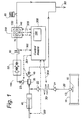
- a preferred embodiment of a system for carrying out the method according to the invention comprises the following major components: A flow system 100, an optical MID-IR spectrometry system 200 and a control system 300 as indicated in fig.1.
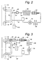
- the flow system may comprise the following components as shown in the three examples Fig. 1 - 3:
- Sample intake means comprising a tube 20 and a pump and valve means, e.g. a piston pump 40 having at least one one-way valve 21, 22 at the pump inlet and at least one one-way valve 23, 45 at the pump outlet.
- the sample intake means 20 is connected to a section of a process conduit 10 from which the samples are taken through a filter 15 and through a detachable connection e.g. mini clamps 13 comprising two flange parts and a gasket. Preferably all such connections are made according to the hygienic standards for food processing plants.
- the process conduit 10 is part of a food processing plant such as a dairy, which is not shown.
- Thermostatizing means 30, preferably comprising: a preheater or cooler, e.g. a coiled steel tube embedded in or wound around an electrically heated copper cylinder, providing e.g. from 1 to 5 ml, preferably 1.5 ml of heated milk or a heated copper cylinder having an inner volume of about 1.5 ml and assigned temperature sensoring means (not shown) connected to control means 300 for controlling the preheater or cooler.
- the heating means 30 are designed to heat e.g. 1.5 ml milk from 1°C to a temperature about 40°C - 50°C in about 25 seconds.
- a high pressure pump 40 (e.g. a LPA/MSC50-h-pump as used in a FOSS ELECTRIC MILKOSCAN 50 or a single stroke pump providing a whole sample volume - e.g. 1.5 ml in one single stroke) provides the high pressure (e.g. about 400-500 bar). Typically at least a pressure of 200 bars is needed for homogenizing. Further the pump yield 40 will ensure a high flow rate through the IR-cuvette during a flushing period, so that the cuvette is cleaned by means of the flow rate of the milk, making further cleaning unnecessary for a number of hours. During the flushing period the pressure across the cuvette may reach 100 - 200 bars.
- the pressure of the measuring branch is maintained at at least the same pressure as the pressure at the location on which the sample is extracted from the process plant.
- the pressure in the measuring branch exceeds the pressure in the process plant.
- the pressure is maintained at a substantially constant level by the use of a back pressure valve 88 as explained later.
- an in-line filter 35 provides a filtered milk passing through the measurement branch comprising the cuvette 70.
- a valve 45 (Fig. 1) allows the milk to bypass the filter, the milk running directly towards waste 90.
- the high flow rate of milk along the inside of the filter 35 will provide a cleaning of the filter 35 when the valve 45 is open.
- the valve 45 can be controlled by the control means 300.
- the valve 45 also act as a safety valve which is set to open if the pressure exceeds e.g. 400 bars.
- a homogenizer 50 e.g. a S4000 as used in FOSS ELECTRIC MILKOSCAN 4000.
- a thorough homogenization of the liquid food product is needed in order to obtain a representative sample (a sample containing all components in the liquid food product) inside the very thin cuvette (typically having a width of 37-50 ⁇ m).
- a further reason for including homogenization is that the scattering of the infra red light passing through the cuvette depends on the particle size of the liquid sample. Accordingly a uniform homogenization is essential in order to have reproducible measurement conditions.
- the pressure drop across the homogenizer is about 200 bars.
- a safety valve also functioning as a contra valve 51 follows immediately after the homogenizer.
- a further preheater or cooler 60 e.g. a coiled tube preferably wound on the periphery of a temperature stabilised IR cuvette, having an electrical resistor soldered to a copper body thermostatizing the milk sample to a predetermined temperature, e.g. to about 40 °C and preferably to 50 °C before entering the cuvette, and preferably comprising assigned temperature sensoring means connected to the control means 300 for controlling the temperature of the preheater or cooler.
- a predetermined temperature e.g. to about 40 °C and preferably to 50 °C before entering the cuvette
- assigned temperature sensoring means connected to the control means 300 for controlling the temperature of the preheater or cooler.
- An IR cuvette 70 comprising a milk flow path and an IR light path crossing the milk flow path.
- the IR cuvette is part of an IR spectro-photo-meter allowing the analysis and/or quantitative determination of specific components of the milk in the IR cuvette.
- the IR cuvette structure includes a bypass milk flow path 83 (Fig. 9) for the auxiliary milk, which is unable to pass through the very thin measurement chamber in the IR cuvette;
- a presently preferred embodiment of the cuvette 70 is shown in Figure 6 - 8 and described in detail later in this specification.
- a back pressure valve 88 maintains a predetermined pressure at the cuvette 70 during the measurement, typically 12 bars, and at least as high as the pressure in the process conduit 10. This pressure will ensure that dissolved gases remain dissolved in the milk in order to avoid air bubbles in the cuvette. Further, in stationary periods (i.e. no flow) the back pressure valve will ensure that the pressure do not exceed 12 bars. A substantially constant pressure in the cuvette is necessary to obtain reliable and reproducible spectrometric measurements.
- An outlet 90 for waste and means (not shown) for collecting or evacuating the waste may be returned to the milk processing plant. This possibility is available because no foreign means or agents have been added to the sample.
- the flow system comprises:
- the inlet 14 opens towards the direction of the process flow in the conduit 10, in such a way that a fraction of the process flow is diverted through the fast-loop.
- the process flow will generate suction, forcing the diverted flow to return into the process conduit 10.
- a sample intake is provided by a tiny flexible tube 20, having an inlet opening with filter communicating with the fast-loop through a detachable connection e.g. so-called mini clamps 19 comprising two flange parts and a gasket
- a detachable connection e.g. so-called mini clamps 19 comprising two flange parts and a gasket
- all such connections are made according to the hygienic standards for food processing plants.
- a pump 40 transfers the sample to a preheater 30, followed by a homogeniser 50, a further preheater 60, an IR-cuvette 70 and a back pressure valve 88.
- the sample may be retumed to the fast-loop through a further tiny tube 91, e.g. a plastic tube or hose. Altematively it may be released as waste.
- the flow system comprises a fast loop 12, connected to a process conduit 10.
- An integrated unit comprising a single stroke pump 40, surrounded by a heater, e.g. a heating coil, forming the first preheater 30, and two one way valves 21, 23 providing that the single stroke pump during a suction stroke takes in milk from the fast loop, and during the pressure stroke sends the milk directly into the homogeniser 50.
- the homogeniser 50 is at the outlet provided with a valve 51 acting as a safety valve or pressure release valve, in order to release an extraordinary high pressure which otherwise might destroy the cuvette.
- a tiny tube 52 carries the homogenised milk to a further preheater 60, the cuvette 70 and the back pressure valve 88 in the same way as in the other embodiments.
- the one way valve 23 is deleted as the one way function is inherently incorporated in the preferred homogenizer 50.
- the optical system 200 for measuring the IR absorption can be chosen between several known MID-IR spectrometric systems, and realised in several ways.
- a scanning interferometer i.e. a FT-IR instrument is used, e.g. an IR-unit as used in FOSS ELECTRIC MILKOSCAN 120.
- the optical system may instead include a filter wheel, comprising a plurality of IR filters appropriate for the desired measurements, e.g. as used in a FOSS ELECTRIC MILKOSCAN 50 or MILKOSCAN 102-104 and as described in GB-B-2 028 498, EP 0 012 492 and EP 0 629 290.
- FIG. 1 and Fig. 4 A simplified diagram of a suitable optical arrangement appears from Fig. 1 and Fig. 4.
- the Box 120 is an IR-source and scanning interferometer, 140 is a detector, and 160 is a computer.
- Scanning interferometers can be realised in several ways, cf., e.g. "Fourier Transform Infrared Spectrometry", Peter R. Griffiths and James A. de Haseth, John Wiley & Sons, 1986, and shall not be the topic of this application.
- the calculations for the determination of the quantities of the components in the milk are performed in the computer 160, and they are also well known to people in the art, e.g. as described in the above reference.
- the IR-cuvette is designed for an optical path length of e.g. 37-50 ⁇ m.
- the IR-cuvette must be made of strong materials, which are resistant to wear and pressure and resistant to mechanical and chemical influences, e.g. materials as used for the process plant itself.
- the IR cuvette is made from a stainless steel and diamond. Accordingly, the IR cuvette can be cleaned by the same liquid means which are used for the milk processing plant anyway in the dairy. Milk processing plants in dairies are regularly, e.g. daily/every 24 hours, flushed with several cleaning liquids, e.g. strong bases and/or acids.
- the diamond and steel materials ensure that the cuvette will not be subjected to any noticeable wear.
- the physical dimensions and properties of the IR light path should be kept constant, preferably for the whole lifetime of the cuvette. Only the milk sample to be tested is changing. This is extremely important to the accuracy and reproducibility of the IR measurements.
- FIG. 5A and Figure 5B An enlarged view of a first example of an embodiment of a cuvette is shown is Figure 5A and Figure 5B.
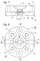
- An alternative embodiment of the IR cuvette is shown as a second example in Figures 6A, 6B, and 7.
- Figure 8 is a schematic top view which applies to both examples. Therefore the sections applied in Figures 5A, 5B are shown on the schematic Figure 8 as well as the section C-C applied in Figure 7.
- the cuvette comprises two steel members 71, 72, e.g. two circular discs.
- the first steel member 71 has a recess for mounting a diamond window 73, and two stepped boreholes 74 (flow channels) for the milk flow.
- the second steel member 72 has a recess for mounting a second diamond window 76.
- the two steel members 71, 72 are tightly secured to each other by fastening means, e.g. four recessed screws (not shown) in threaded bores 79.
- one of the steel members 71 may have a recessed central area in which a protruding portion 69 of the other steel member 72 can intrude or visa versa.
- the cuvette is preferably connected in the flow system by tiny tubes 78 which are inserted in each borehole 74. For the sake of clarity only one tube 78 is shown.
- the first steel member 71 has an upper stepped opening 77 provided for an IR light beam 121 from the optical system 200 in Figure 4, and the second steel member 72 has a lower stepped opening 75 provided for a detector 140 in the optical system.
- An alternative arrangement is shown in the embodiment of Figures 6A, 6B and 7.
- the first steel member 71 has the stepped opening 75 provided for the detector 140 in the optical system
- the second steel member 72 has the stepped opening 77 provided for an IR light beam 121 from the optical system.
- the two bore holes form a mutual angle of about 100° - 140°, preferably 120° - 125°.
- the bore hole 74 be inclined to form an angle ⁇ (not shown in the drawings) with the interface between the two steel members 71, 72, where ⁇ is between 0° and 30°, preferably between 5° and 15°, and most preferably about 10°.
- the adjacent bore (84 in Figure 9) forms an angle ⁇ (not shown in the drawings) with the interface between the two steel members 71, 72, where ⁇ is between about 40° and 85° , preferably between 55° and 80°, and most preferably between 60° and 75°.
- a thin spacer 81 is used to support the peripheral rims of the diamond windows thereby ensuring the desired height (equal to the optical path length, e.g. 37 - 50 ⁇ m ) of the inner measurement chamber 80 of the cuvette, when the two steel members are assembled.
- the spacer 81 can be a thin circular disc having a circular opening forming the measurement chamber 80, two slots 89, connecting the chamber 80 to the thin bore holes 84, and a pair of guide holes 87' for guide pins 87, used to help positioning the spacer 81 when the cuvette is assembled.
- the bore holes 85, 86 appearing in the sectional view of Figure 7 are used for mounting the cuvette on holding means (not shown).
- the item 82 is an O-ring ensuring that no milk can intrude in the interface between the two cuvette parts.
- the bore holes 74 and openings 75, 77 are stepped, having stepwise or gradually decreasing diameters, in order to accomodate the inlet and outlet of liquid and IR light to the small measurement chamber 80 in the centre of the cuvette.
- the measurement chamber 80 containing the milk sample to be measured is hardly visible.
- the measurement chamber can be, e.g. about 2 - 3 mm in diameter and about 30 - 50 ⁇ m in width (equal to the optical path length).
- the actual dimensions in a cuvette in an apparatus according to the invention may depend on the milk or food product to be measured and the parameters wanted.
- Figure 9 shows a section through the centre of the cuvette further enlarged in a large scale view, in order to show the inner details of a presently preferred embodiment.
- Milk flowing through the measuring branch enters the cuvette 70 through the tiny tube 78 at the bore 74 (Fig.5A) passing the adjacent bore 84 (Fig. 5A and Fig. 9), flows through the slot 89 into the measurement chamber 80 and exits from the cuvette through the opposite slot 89 and the bores 84, 74.
- this flow is forced into a thin (e.g. 30-50 ⁇ m thick) and relatively wide (e.g. 0.5 - 2 mm) flow passing the thin circular measurement chamber 80 between the diamond windows 73, 76.
- An optional bypass flow path 83 may be provided along the periphery of the windows 73, 76. If the track 83 is provided, preferably it can be restricted and possibly obstructed in order to ensure the measurement chamber is flushed thoroughly with the liquid to be measured.
- Figure 10 shows the spacer 81 and the adjacent track 83 and inlet and outlet bores 84. However in the presently preferred embodiment the cuvette has no bypass track 83.
- the spacer has a wedge form, i.e. having slightly inclined surfaces, providing a difference in light path of from 3 to 10 ⁇ m, preferably from 4 to 8 ⁇ m and most preferred about 6 ⁇ m, across the window opening for the IR light, thereby providing a light path varying e.g. from about 34 to 40 ⁇ m across the 2 mm opening.
- a wedge form i.e. having slightly inclined surfaces, providing a difference in light path of from 3 to 10 ⁇ m, preferably from 4 to 8 ⁇ m and most preferred about 6 ⁇ m, across the window opening for the IR light, thereby providing a light path varying e.g. from about 34 to 40 ⁇ m across the 2 mm opening.
- a control system 300 preferably including a computer, e.g. a PC with adequate software, monitors and adjusts the temperature at the cuvette.
- the humidity of the optical system 200 is monitored, and connected to an visual or audial alarm function to inform attendant personal that the system need attention, e.g. purging by a suitable gas in order to remove any humidity, as water vapour in the optical path will cause a deterioration of the measurements.
- a suitable gas e.g. purging by a suitable gas in order to remove any humidity, as water vapour in the optical path will cause a deterioration of the measurements.
- means for removing humidity can be included in the optical system.
- the control system is connected to the pump 40 and valves 23, 45 for control of their operation.
- the temperature control means comprise a sensor located at a copper member enclosing the cuvette and a heat resistor able to heat the copper member in order to temperature stabilise the cuvette.
- the pump 40 is of a type using several pump strokes to provide a sample
- the method according to the invention is carried out as follows: During a first step of a few seconds duration, e.g. two seconds, the pump 40 is activated by the control means 300. A milk sample is extracted from the process conduit 10 through the fast loop 12 towards the measuring system by the pump. During a second step the milk sample (e.g. 1,5 ml milk) is temperature stabilised (heated or cooled) by the means 30. The milk sample stays in the preheater 30 for a period of time, e.g. 25 sec's to attain a predetermined temperature, e.g. 50°C which is suitable for the homogenizer 50.
- a predetermined temperature e.g. 50°C which is suitable for the homogenizer 50.
- the pump starts working again, providing a high pressure pushing the heated milk sample through the homogenizer, in which the fat globules of the milk are crunched. From the homogenizer the milk sample flows through the further preheater 60 located upstream the IR cuvette to ensure the sample has the correct temperature for the measurement in the IR cuvette 70.
- the pump is active for about two seconds and preferably less to displace about 1.5 ml through a thin steel tube preferably having a diameter of less than 1 mm ⁇ . e.g. 0,7 mm, connected to the inlet of the cuvette and through the cuvette, through a further thin steel tube connected to the outlet of the cuvette, to the back pressure valve 88 and out of the measuring branch, either to a waste outlet or returned to the fast loop.
- the major part of the 1.5 ml is flushed through the cuvette with a high flow rate. Assuming a spacer thickness of 50 ⁇ m, the sectional area of the cuvette inlet i.e.
- a laminar flow may be promoted.
- a sharp transition as shown in Figure 10 may promote a turbulent flow, which is believed to have a cleaning effect on the cuvette windows.
- the steel tube leading to the cuvette has an inner area of about 0.4 mm 2 providing a flow rate of about 1.9 m/s.
- a fraction of the new preheated sample is present in the cuvette.
- the pressure inside the cuvette will stay at a constant level, of about 10 - 20 bars preferably 12 bar, due to the back pressure valve 88.
- the following step is about 25 sec's long.
- the sample is analysed by the IR-spectrometer.
- a new sample is extracted from the fast loop.
- the new sample is heated during the following about 25 sec's long step while a portion of the already heated (preceding) sample is measured in the cuvette. And so on. Accordingly, a new sample can be introduced approximately every 30 seconds, corresponding to about 120 measurements per hour.
- the pump 40 is a single stroke pump surrounded by heating means, e.g. a coil.
- the method is carried out as follows: In a first step of about two sec's a sample is sucked into the pump cylinder by one suction stroke of the piston. Then in a second step the sample is heated inside the pump cylinder for about 25 secs. In a third preferably short step of about 0.5 - 1.0 sec. duration the piston stroke is reversed, pushing the new sample through the homogenizer and partly through the cuvette and the back pressure valve. Thereby the old sample is flushed away either into a waste outlet 90 or returned into the fast loop and the process conduit. If the third step is performed in 0.5 sec.
- the flushing rate through the cuvette will be about 10 - 30 m/s with a displaced milk volume of about 1.5 ml. This flushing rate will ensure a thorough cleaning of the cuvette windows between each measurement.
- the advantage of the third embodiment is that the suction stroke may be slow (to avoid cavitation) and the reverse pumping stroke can be fast, thereby providing a high flushing rate and a better cleaning of the cuvette. Also in this embodiment a measurement rate of about 120 samples per hour is possible.
- a pressure transducer 95 and optionally a flow meter 94 is included, preferably between the cuvette 70 and the back pressure valve 88.
- the pressure transducer provides a monitoring of the flow system. It will reveal any leakage in the flow system during the measurement. During the measurement stable conditions are essential to ensure reproducibility of the measurements.
- a further advantage is that by measuring the pressure increase (and optionally the flow rate) during flushing the pressure transducer (and optionally the flow meter) provides means for indicating whether the flushing of the cuvette has been sufficient.
- the preferred embodiment includes an optional arrangement for the intake of a pilot sample in order to monitor the performance of the instrument.
- a pipette 96 can be arranged to aspirate a pilot sample from a cup (which is not shown).
- a pilot sample has a known specific composition, providing a specific measurement result. In case the actually obtained result differs from the expected values, this indicates that the instrument needs adjustment.
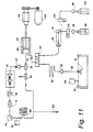
- the pipette 96 is arranged to be placed in a holder 97 through which it is included in the flow path from a rinsing/cleaning liquid reservoir 100 to the pump 40 when it is not in use for aspiration of a pilot sample.
- the provision of the reservoirs 99, 100 for rinsing/cleaning liquid and zero liquid provides for the possibility to arrange a fast cleaning of the cuvette 70 whenever needed. In a presently preferred embodiment a regular cleaning every two hours is recommended.
- the liquids are preheated in heaters 98 to the same temperature as the milk samples before entering the measuring branch and the cuvette. Thereby the cleaning can be carried out fast as the heating step (about 25 sec) in the single stroke pump 40 can be dispensed with.
- the sample pipette 96 is applied for introducing the rinsing/cleaning liquid from the rinsing/cleaning liquid reservoir 100 and/or a zero liquid from a zero liquid reservoir 99.
- FIG. 11 the intake is shown through a valve 101 (e.g. a 3/2 way valve) located after (downstream) the sample heater/cooler 30, but the intake may also be located before (upstream) the heater/cooler.
- a valve 101 e.g. a 3/2 way valve
- Two 2/2 way valves 102, 103 are provided adjacent to the heaters 98 for control of the supply of zero liquid and rinsing/cleaning liquid.
- a linear actuator 104 and a motor 105 for driving the single stroke pump 40.
- 106 indicate an in-line monitoring of the temperature in the process line 10. All components in Figure 11 having reference numbers used in the previous Figures 1- 3 are similar to and act the same way as already described with reference to said Figures.
- the flow system i.e. the measuring branch
- the flow system is capable to withstand standard cleaning procedures for milk plants. Slow build up of deposits on the IR windows of the cuvette is avoided by exposing the cuvette to the standard cleaning procedures of the plant. This may be a so-called "CIP" (Clean In Place”) procedure that uses heated acid and base solutions. During cleaning the typical flow rate will be below 10 m/s in the conduits of the milk plant but much higher in the cuvette.
- CIP Cosmetic In Place
- a number of the cleaning or rinsing liquids of the dairy are used as a calibration liquid for an adjustment or calibration of the optical part and specifically for an adjustment of the calculation and calibration software used for the calculation of the amounts of the tested components.
- a spectrum measured on a liquid containing, e.g. NO 3 -ions and/or PO 4 3- -ions, may be used for an adjustment or calibration of the frequencylwavelength - axe.
Landscapes
- Physics & Mathematics (AREA)
- Health & Medical Sciences (AREA)
- Life Sciences & Earth Sciences (AREA)
- Chemical & Material Sciences (AREA)
- Spectroscopy & Molecular Physics (AREA)
- Immunology (AREA)
- Analytical Chemistry (AREA)
- General Physics & Mathematics (AREA)
- Biochemistry (AREA)
- Pathology (AREA)
- General Health & Medical Sciences (AREA)
- Engineering & Computer Science (AREA)
- Food Science & Technology (AREA)
- Medicinal Chemistry (AREA)
- Investigating Or Analysing Materials By Optical Means (AREA)
- Optical Measuring Cells (AREA)
- Electron Tubes For Measurement (AREA)
- Automatic Analysis And Handling Materials Therefor (AREA)
- Other Investigation Or Analysis Of Materials By Electrical Means (AREA)
Abstract
Description
When the
Claims (22)
- A method for carrying out spectrometry for analysis of a liquid food product, possibly containing dissolved gases, in a process line in a liquid food processing plant, and comprising the following steps:characterised in that the method further comprisesproviding a liquid sample from the process line to a measuring branch, including a measurement cuvette (70),thermostating the liquid sample,passing the thermostated liquid food sample into the measurement cuvette,measuring at least a portion of the absorbance spectrum of the liquid food sample in the measurement cuvette,extracting the liquid food sample directly from the process line into the measuring branch,during a measurement period providing and maintaining a pressure inside the measuring branch, including the cuvette, said pressure being at least as high as the pressure in the said process line,before each measurement flushing the cuvette with a portion of the extracted liquid food sample, the flushing being performed under a pressure between 50 and 200 bars across the cuvette, andfurther having provided that the cuvette has windows of a pressure and wear resistant material.
- A method according to claim 1, characterised in that the liquid food processing plant is a dairy plant and that a regular cleaning of the measuring branch including the cuvette is performed when the dairy plant is subjected to the regular cleaning process and/or by flushing the measurement branch with the same cleaning solutions used for cleaning the dairy plant.
- A method according to claim 1, characterised in that a regular cleaning of the measuring branch including the cuvette is performed by flushing the measurement branch with a preheated cleaning liquid provided from a reservoir (100) arranged to be connected in fluid communication with the measuring branch.
- A method according to claim 2, characterised in that at least one of the cleaning and/or rinsing liquids of the dairy is used in the measuring branch for an adjustment, such as a standardization, based on characteristics in the measured spectrum or spectra of the cleaning and/or rinsing liquids, especially characteristics originating from the appearance of ions belonging to the group comprising NO3-ions and PO4 3-.
- A method according to claim 1, characterised in that the spectrometry is performed in the IR spectral range, preferably in the MID-IR and/or the NIR spectral range.
- A method according to claim 1, characterised in that the liquid food sample is thermostated while it is maintained inside the cylinder of a single stroke pump (40).
- A flow system for in-line extraction of a sample stream from a liquid food processing plant, such as a dairy processing milk and milk products, and for carrying out the method according to any of the claims 1-6, characterised inthe flow system being directly connected to the liquid food processing plant,the flow system including a measurement cuvette (70) for spectrometric measurements for analysis of a liquid food product in the liquid food processing plant,the flow system further comprising pump means (40) and back pressure valve means (88) able to maintain a predetermined pressure inside the cuvette during a measurement period, said pressure being at least as high as the pressure inside the process line, andthe pump means further being able to provide a flushing before each measurement, said flushing being performed under a pressure between 50 and 200 bars across the cuvette, andthe cuvette having windows of a pressure resistant material.
- A flow system according to claim 7, characterised in that the measurement cuvette has diamond windows (73, 76).
- A flow system according to claim 7 or 8, characterised in that the pump means is a single stroke pump (40 in Figure 1 and 3).
- A flow system according to claim 9, characterised in that the cylinder of the single stroke pump (40) is provided with thermostating means (30).
- A flow system according to claim 7, characterised in that the measuring branch of the flowsystem (100) comprises a homogenizer (50) located upstream the cuvette (70), and at least one preheater (30, 60) located upstream the cuvette (70) and/or the homogenizer (50).
- A flow system according to any of the claims 7 - 11, characterised in that a pilot sample pipette (96) is provided, said pipette being connectable to the intake of the pump (40) through valve means (101, 22).
- A flow system according to claim 12, characterised in that a holder (97) is provided for the pilot sample pipette (96) to be arranged in the holder (97) when it is not immersed in a pilot sample cup, and that the pilot sample pipette (96) when located in the holder is included in a fluid path from a reservoir (100) for a rinsing/cleaning liquid and/or a reservoir (99) for a zeroliquid through valve means (102, 103).
- A measurement cuvette for a flow system according to any of the claims 7 - 13, the cuvette enclosing an IR measurement chamber (80) between two diamond windows and comprising:characterised by the cuvette further comprisingtwo openings (77, 75) provided for an IR light beam coming from an IR-source (120), and for arrangement of an optical detector (140), the inner end of each opening being sealingly closed by diamond discs, (73, 76), forming the windows,and bore holes (74, 84) for inlet and outlet of a liquid flow to and from the IR measurement chamber (80),a first and a second steel member (71, 72), enclosing the IR measurement chamber (80), each steel member having one of the openings for the IR light beam and the optical detector (140),the first steel member having the bore holes (74,84) for inlet and outlet of a liquid flow to and from the IR measurement chamber (80),a metal spacer (81) being arranged between the diamond windows (73, 76) and along the periphery of the measurement chamber,and the two steel members (71, 72) with diamond windows (73, 76) and spacer (81) being tightly secured to each other by fastening means (79).
- Cuvette according to claim 14, characterised in that at least one of the bore holes (74) is inclined, forming an angle α with the interface between the two steel members (71, 72), and α being between 0° and 30° preferably between 5° and 15° and most preferably approximately 10°.
- Cuvette according to claim 14 or 15, characterised in that the adjacent bore (84 in Fig. 9) is inclined, forming an angle β with the interface between the two steel members (71, 72), and β being between 40° and 85°, preferably between 55° and 80° and most preferably between 60° and 75°.
- Cuvette according to any of the claims 14-16, characterised in that a bypass flow path (83) is provided along the periphery of the measurement chamber and/or along the periphery of the diamond windows (73, 76) or the spacer (81).
- Cuvette according to any of the claims 14 - 17, characterised in that an O-ring (82) is arranged along the periphery of the spacer, outside the spacer and/or along the outer periphery of the bypass flow path (83).
- Cuvette according to claim 14, characterised in that the spacer (81) is made of steel.
- Cuvette according to claims 14, characterised in that the spacer (81) has wedge form, i.e. having slightly inclined surfaces, providing a difference in light path of from 3 to 10 µm, preferably from 4 to 8 µm and most preferred about 6 µm, across the window opening for the IR light.
- Cuvette according to any of the claim 14, characterised in that the spacer (81) is provided with slots (89) for the flow of liquid to and from the measurement chamber between the diamond windows in the centre of the cuvette.
- Cuvette according to any of the claims 14, characterised in that at least one of the bore holes (74) and openings (75, 77) is stepped, i.e. having stepwise decreasing diameter from the outside towards the centre of the cuvette.
Applications Claiming Priority (3)
| Application Number | Priority Date | Filing Date | Title |
|---|---|---|---|
| DK199601221A DK173073B1 (en) | 1996-11-01 | 1996-11-01 | Process and flow system for spectrometry and a cuvette for the flow system |
| DK122196 | 1996-11-01 | ||
| PCT/DK1997/000492 WO1998020338A1 (en) | 1996-11-01 | 1997-10-31 | A method and flow system for spectrometry and a cuvette for the flow system |
Publications (2)
| Publication Number | Publication Date |
|---|---|
| EP0935749A1 EP0935749A1 (en) | 1999-08-18 |
| EP0935749B1 true EP0935749B1 (en) | 2002-08-28 |
Family
ID=8102351
Family Applications (1)
| Application Number | Title | Priority Date | Filing Date |
|---|---|---|---|
| EP97911146A Expired - Lifetime EP0935749B1 (en) | 1996-11-01 | 1997-10-31 | A method and flow system for spectrometry and a cuvette for the flow system |
Country Status (12)
| Country | Link |
|---|---|
| US (1) | US6297505B1 (en) |
| EP (1) | EP0935749B1 (en) |
| JP (1) | JP4105235B2 (en) |
| KR (1) | KR100516530B1 (en) |
| AT (1) | ATE223041T1 (en) |
| AU (1) | AU731963B2 (en) |
| CA (1) | CA2270222C (en) |
| DE (1) | DE69715024T2 (en) |
| DK (1) | DK173073B1 (en) |
| NZ (1) | NZ335597A (en) |
| PL (1) | PL186428B1 (en) |
| WO (1) | WO1998020338A1 (en) |
Cited By (2)
| Publication number | Priority date | Publication date | Assignee | Title |
|---|---|---|---|---|
| CN105556281A (en) * | 2013-09-27 | 2016-05-04 | 西门子公司 | Flow apparatus for a spectrometer system and method for operating same |
| US9683927B2 (en) | 2011-12-02 | 2017-06-20 | Biochrom Limited | Device for receiving small volume liquid samples |
Families Citing this family (48)
| Publication number | Priority date | Publication date | Assignee | Title |
|---|---|---|---|---|
| JP3453282B2 (en) | 1997-06-25 | 2003-10-06 | 株式会社堀場製作所 | Analyzer with cooling device |
| WO1999023473A1 (en) | 1997-10-31 | 1999-05-14 | Foss Electric A/S | A cuvette and spacer therefor as well as a method of producing the spacer |
| AU5726999A (en) * | 1998-09-18 | 2000-04-10 | Foss Electric A/S | Method and apparatus for process control |
| FR2801383B1 (en) * | 1999-11-19 | 2002-06-28 | Federation Francaise De Contro | COMPACT OPTICAL PROBE AND ASSOCIATED MEASUREMENT METHOD |
| DE10013374A1 (en) * | 2000-03-17 | 2001-09-27 | Abb Patent Gmbh | Gas analyzer device and method for operating the same |
| ATE280492T1 (en) | 2001-03-07 | 2004-11-15 | Lattec I S | ARRANGEMENT FOR OPTIMIZING THE PRODUCTION PERFORMANCE OF A DAIRY HERD |
| DE10118329A1 (en) * | 2001-04-12 | 2002-10-24 | Westfalia Landtechnik Gmbh | Determination of milk properties, particularly milk for transportation, by determination of a color vector from an optical spectrum of the milk, with the vector used to represent milk characteristics |
| JP2003042948A (en) * | 2001-08-03 | 2003-02-13 | Univ Waseda | Glucose concentration measuring device |
| DE60330840D1 (en) * | 2002-02-11 | 2010-02-25 | Foss Analytical As | METHOD FOR DETERMINING CASEIN IN MILK |
| FR2822951B1 (en) * | 2002-03-28 | 2005-02-04 | Federation Francaise De Contro | COMPACT OPTICAL PROBE AND ASSOCIATED MEASUREMENT METHOD |
| US6741348B2 (en) * | 2002-04-29 | 2004-05-25 | The Curators Of The University Of Missouri | Ultrasensitive spectrophotometer |
| US6894777B2 (en) * | 2002-08-07 | 2005-05-17 | Romaine R. Maiefski | Multiple-channel UV spectrometer assembly |
| US7162971B2 (en) | 2002-12-19 | 2007-01-16 | Lattec I/S | Milk conveyer device |
| SE524587C2 (en) * | 2003-02-18 | 2004-08-31 | Delaval Holding Ab | Method and apparatus for counting somatic cells or small drops of fat in milk |
| US20040219266A1 (en) * | 2003-04-30 | 2004-11-04 | Milliken Adam S. | Determination of homogenization efficiency based on light transmittance |
| DE10336875A1 (en) * | 2003-08-11 | 2005-03-17 | Bayer Chemicals Ag | Spectroscopic concentration determination in a rectification column |
| US7268881B2 (en) * | 2004-02-17 | 2007-09-11 | The Curators Of The University Of Missouri | Light scattering detector |
| US20060286676A1 (en) * | 2005-06-17 | 2006-12-21 | Van Camp James R | Fluorometric method for monitoring a clean-in-place system |
| US7479257B2 (en) * | 2005-08-26 | 2009-01-20 | Ethicon, Inc. | Automated endoscope reprocessor solution testing |
| CN101755204A (en) | 2006-03-09 | 2010-06-23 | 全技术联合公司 | Evaporative light-scattering detector |
| CN101495849B (en) | 2006-07-31 | 2013-01-30 | 应用材料公司 | Methods and apparatuses for insitu analysis of gases in electronic device fabrication systems |
| US7593101B2 (en) | 2007-04-10 | 2009-09-22 | Schlumberger Technology Corporation | High-pressure cross-polar microscopy cells having adjustable fluid passage and methods of use |
| US8246909B2 (en) * | 2007-08-29 | 2012-08-21 | Ethicon, Inc. | Automated endoscope reprocessor germicide concentration monitoring system and method |
| KR100975751B1 (en) * | 2008-05-23 | 2010-08-12 | 성균관대학교산학협력단 | Real-time portable quality determination system of crude oil |
| US20110083493A1 (en) * | 2008-06-11 | 2011-04-14 | The Curators Of The University Of Missouri | Liquid Chromatography Detector and Flow Controller Therefor |
| NZ610613A (en) * | 2010-12-03 | 2015-02-27 | Foss Analytical As | Mid-infrared spectral analysis of a flowing heterogeneous material |
| EP2739635B1 (en) * | 2011-08-05 | 2016-04-20 | Wyatt Technology Corporation | Bubble suppressing system for optical measurement cells |
| US9606050B2 (en) | 2011-08-19 | 2017-03-28 | Foss Analytical A/B | Method for compensating amplitude drift in a spectrometer and spectrometer performing said method |
| BR112014004156B1 (en) | 2011-08-24 | 2020-10-27 | Perkinelmer Analytical Solutions B.V | sample cell for spectrophotometric analysis go from a liquid sample, and use of a sample cell |
| US8663562B2 (en) | 2011-09-13 | 2014-03-04 | Sabic Innovative Plastics Ip B.V. | Flow cell for measuring electromagnetic radiation absorption spectra in a continuously flowing immiscible liquid(s) or liquids with entrained gas phases |
| WO2013081534A1 (en) | 2011-12-01 | 2013-06-06 | Delaval Holding Ab | Milking system and method for cleaning in a milking system |
| EP3017291A4 (en) * | 2013-07-03 | 2017-01-25 | Wyatt Technology Corporation | Method and apparatus to control sample carryover in analytical instruments |
| US20150247210A1 (en) | 2014-02-28 | 2015-09-03 | Asl Analytical, Inc. | Methods for Continuous Monitoring and Control of Bioprocesses |
| FI126449B (en) | 2014-06-11 | 2016-12-15 | Janesko Oy | Method and arrangement for measuring an incremental sample of process fluid |
| JP6491746B2 (en) * | 2014-10-07 | 2019-03-27 | フォス アナリティカル アグシャセルスガーッブFoss Analytical A/S | Liquid analyzer |
| JP2015064370A (en) * | 2014-11-12 | 2015-04-09 | フォス アナリティカル アグシャセルスガーッブFoss Analytical A/S | Mid-infrared spectral analysis of flowing heterogeneous materials |
| EP3045891A1 (en) * | 2015-01-13 | 2016-07-20 | Nemewo ApS | Optical characterization system for a process plant |
| RU2688954C2 (en) * | 2015-06-01 | 2019-05-23 | ФОСС Аналитикал А/С | Spectral analysis of a fluid inhomogeneous medium in the middle infrared range |
| BG67049B1 (en) | 2016-04-12 | 2020-04-15 | „Бултех 2000“ Оод | Device and method of milk analysis |
| JP6765239B2 (en) * | 2016-07-12 | 2020-10-07 | 日本ピラー工業株式会社 | Diaphragm pump |
| WO2018148809A1 (en) * | 2017-02-15 | 2018-08-23 | Bulteh - 2000 Ltd | Cuvette for analysis of fluid food products |
| EP3707504B1 (en) * | 2017-11-07 | 2025-12-17 | S.C.R. (Engineers) Limited | System and method for analysis of a fluid |
| DE102018107322A1 (en) * | 2018-03-27 | 2019-10-02 | MAX-PLANCK-Gesellschaft zur Förderung der Wissenschaften e.V. | Measuring cell and measuring device |
| DE102018111675A1 (en) | 2018-05-15 | 2019-11-21 | Gea Farm Technologies Gmbh | Measuring arrangement for optical measurements of milk during a milking process |
| BG67448B1 (en) | 2018-11-07 | 2022-07-15 | Екомилк Спектра ООД | Device and a method for analysis of the qualities of liquid foods with simultaneous detection of impurities therein |
| DE102019205575A1 (en) * | 2019-04-17 | 2020-10-22 | Mahle International Gmbh | Device for cooling a vehicle battery |
| BR112023006178A2 (en) | 2020-11-02 | 2023-05-09 | Foss Analytical As | METHOD AND ANALYZER FOR THE OPTICAL ANALYSIS OF A LIQUID CONTAINING A DISSOLVED GAS |
| US12402596B2 (en) | 2022-05-03 | 2025-09-02 | S.C.R. (Engineers) Limited | Milk channel and feed inlet coupled thereto, and system and method for conserving wash fluid in a washing process for cleaning a milkmeter system |
Family Cites Families (16)
| Publication number | Priority date | Publication date | Assignee | Title |
|---|---|---|---|---|
| GB1305214A (en) * | 1970-10-28 | 1973-01-31 | ||
| US3781116A (en) | 1971-10-14 | 1973-12-25 | Coulter Chemistry Inc | Colorimeter with automatic cuvette |
| US3886364A (en) | 1973-06-19 | 1975-05-27 | Union Carbide Corp | High pressure infrared cell |
| US4144804A (en) | 1976-10-12 | 1979-03-20 | On-Line Instrumentation, Inc. | Apparatus for continuously controlling butterfat content of reconstituted milk |
| US4239394A (en) * | 1977-04-08 | 1980-12-16 | A/S Foss Electric | Liquid analyzing apparatus |
| US4236075A (en) | 1978-08-07 | 1980-11-25 | A/S N. Foss Electric | Apparatus for measuring components of liquid samples |
| DK151393C (en) | 1978-12-06 | 1988-05-16 | Foss Electric As N | PROCEDURE FOR QUANTITATIVE DETERMINATION OF FAT IN A WATER FAT EMULSION |
| DE3132163C2 (en) | 1981-08-14 | 1987-03-05 | Bayer Ag, 5090 Leverkusen | Device for the continuous investigation of chemical reactions in the liquid phase by means of infrared absorption |
| FI65672C (en) | 1982-09-09 | 1984-06-11 | Kainuun Osuusmeijeri | FOERFARANDE FOER TAGNING AV MJOELKPROV OCH VID FOERFARANDET ANAENDBAR ANORDNING |
| DE3855720T2 (en) | 1987-08-18 | 1997-05-22 | Bp Oil Int | Method for the direct determination of the physical properties of hydrocarbon products |
| DE3822445A1 (en) * | 1988-07-02 | 1990-01-04 | Bruker Analytische Messtechnik | OPTICAL HIGH PRESSURE TRANSMISSION CELL |
| US4910403A (en) * | 1988-11-02 | 1990-03-20 | Flow Vision, Inc. | Sampling flow cell with diamond window |
| US5137738A (en) | 1989-05-16 | 1992-08-11 | Wedgewood Technology, Inc. | System and method for controlling butterfat content in standardized milk product using whole product sensor |
| US5046854A (en) * | 1990-02-01 | 1991-09-10 | The Dow Chemical Company | Photometric cell and probe having windows fusion sealed to a metallic body |
| US6395228B1 (en) | 1991-11-27 | 2002-05-28 | Marathon Ashland Petroleum Llc | Sampling and analysis system |
| DK39792D0 (en) | 1992-03-25 | 1992-03-25 | Foss Electric As | PROCEDURE FOR DETERMINING A COMPONENT |
-
1996
- 1996-11-01 DK DK199601221A patent/DK173073B1/en not_active IP Right Cessation
-
1997
- 1997-10-31 KR KR10-1999-7003872A patent/KR100516530B1/en not_active Expired - Fee Related
- 1997-10-31 JP JP52095698A patent/JP4105235B2/en not_active Expired - Fee Related
- 1997-10-31 EP EP97911146A patent/EP0935749B1/en not_active Expired - Lifetime
- 1997-10-31 CA CA002270222A patent/CA2270222C/en not_active Expired - Fee Related
- 1997-10-31 AU AU48628/97A patent/AU731963B2/en not_active Ceased
- 1997-10-31 AT AT97911146T patent/ATE223041T1/en not_active IP Right Cessation
- 1997-10-31 NZ NZ335597A patent/NZ335597A/en unknown
- 1997-10-31 WO PCT/DK1997/000492 patent/WO1998020338A1/en not_active Ceased
- 1997-10-31 PL PL97333234A patent/PL186428B1/en not_active IP Right Cessation
- 1997-10-31 DE DE69715024T patent/DE69715024T2/en not_active Expired - Fee Related
- 1997-10-31 US US09/297,331 patent/US6297505B1/en not_active Expired - Fee Related
Cited By (2)
| Publication number | Priority date | Publication date | Assignee | Title |
|---|---|---|---|---|
| US9683927B2 (en) | 2011-12-02 | 2017-06-20 | Biochrom Limited | Device for receiving small volume liquid samples |
| CN105556281A (en) * | 2013-09-27 | 2016-05-04 | 西门子公司 | Flow apparatus for a spectrometer system and method for operating same |
Also Published As
| Publication number | Publication date |
|---|---|
| DE69715024D1 (en) | 2002-10-02 |
| NZ335597A (en) | 2000-02-28 |
| JP2001509254A (en) | 2001-07-10 |
| US6297505B1 (en) | 2001-10-02 |
| DE69715024T2 (en) | 2003-01-02 |
| DK173073B1 (en) | 1999-12-20 |
| ATE223041T1 (en) | 2002-09-15 |
| AU731963B2 (en) | 2001-04-05 |
| AU4862897A (en) | 1998-05-29 |
| KR20000052993A (en) | 2000-08-25 |
| PL333234A1 (en) | 1999-11-22 |
| KR100516530B1 (en) | 2005-09-26 |
| JP4105235B2 (en) | 2008-06-25 |
| WO1998020338A1 (en) | 1998-05-14 |
| PL186428B1 (en) | 2004-01-30 |
| CA2270222C (en) | 2006-05-09 |
| CA2270222A1 (en) | 1998-05-14 |
| DK122196A (en) | 1998-05-02 |
| EP0935749A1 (en) | 1999-08-18 |
Similar Documents
| Publication | Publication Date | Title |
|---|---|---|
| US6297505B1 (en) | Method and flow system for spectrometry and a cuvette for the flow system | |
| US5594161A (en) | Method and apparatus for rapidly testing the integrity of filter elements | |
| US8336375B2 (en) | Flow cell assembly for fluid sensors | |
| CN1147854A (en) | Sampling and analysis system and method | |
| EP0774657A2 (en) | Liquid detection method and device therefor | |
| JPH08505477A (en) | Fluid medium analyzer | |
| US4804519A (en) | Sample analysis apparatus | |
| US6069694A (en) | Flow cell | |
| US4310763A (en) | Electro-optical analyzer for measuring percentage by weight of fat, protein and lactose in milk | |
| CA2001615A1 (en) | Sampling flow cell with diamond window | |
| US4447775A (en) | Apparatus and method for continuous pH monitoring | |
| Langenbucher et al. | Dissolution rate testing with the column method: methodology and results | |
| US5044747A (en) | Modular flow-through cell | |
| US20230168179A1 (en) | Flow cell assembly and spectroscopy device assembly for use in a bioprocess | |
| WO2002075284A2 (en) | Flow-through cell | |
| WO2004009230A1 (en) | A sampling apparatus | |
| US5553484A (en) | High flow membrane probe | |
| JP2003510605A (en) | Chemical sensing system | |
| EP0993618B1 (en) | Method and apparatus for determining the content of a component in a fluid sample | |
| GB2312745A (en) | Determining a parameter of a substance, especially a hydrocarbon | |
| EP1131617B1 (en) | Measuring of fiber properties | |
| GB2149531A (en) | A method of passing a liquid sample from a sample container into a measuring cell or a cuvette and a measuring apparatus with a measuring cell or cuvette | |
| JPS6093940A (en) | Sampling apparatus | |
| EP1554558A1 (en) | Procedure and instrument for measurement of the characteristics of fluids | |
| WO2025131467A1 (en) | Bioprocess assembly with integrated filtration and sampling systems |
Legal Events
| Date | Code | Title | Description |
|---|---|---|---|
| PUAI | Public reference made under article 153(3) epc to a published international application that has entered the european phase |
Free format text: ORIGINAL CODE: 0009012 |
|
| 17P | Request for examination filed |
Effective date: 19990519 |
|
| AK | Designated contracting states |
Kind code of ref document: A1 Designated state(s): AT BE CH DE ES FI FR GB GR IE IT LI NL PT SE |
|
| 17Q | First examination report despatched |
Effective date: 20001024 |
|
| GRAG | Despatch of communication of intention to grant |
Free format text: ORIGINAL CODE: EPIDOS AGRA |
|
| GRAG | Despatch of communication of intention to grant |
Free format text: ORIGINAL CODE: EPIDOS AGRA |
|
| GRAG | Despatch of communication of intention to grant |
Free format text: ORIGINAL CODE: EPIDOS AGRA |
|
| GRAH | Despatch of communication of intention to grant a patent |
Free format text: ORIGINAL CODE: EPIDOS IGRA |
|
| GRAH | Despatch of communication of intention to grant a patent |
Free format text: ORIGINAL CODE: EPIDOS IGRA |
|
| GRAA | (expected) grant |
Free format text: ORIGINAL CODE: 0009210 |
|
| AK | Designated contracting states |
Kind code of ref document: B1 Designated state(s): AT BE CH DE ES FI FR GB GR IE IT LI NL PT SE |
|
| PG25 | Lapsed in a contracting state [announced via postgrant information from national office to epo] |
Ref country code: LI Free format text: LAPSE BECAUSE OF FAILURE TO SUBMIT A TRANSLATION OF THE DESCRIPTION OR TO PAY THE FEE WITHIN THE PRESCRIBED TIME-LIMIT Effective date: 20020828 Ref country code: IT Free format text: LAPSE BECAUSE OF FAILURE TO SUBMIT A TRANSLATION OF THE DESCRIPTION OR TO PAY THE FEE WITHIN THE PRE;WARNING: LAPSES OF ITALIAN PATENTS WITH EFFECTIVE DATE BEFORE 2007 MAY HAVE OCCURRED AT ANY TIME BEFORE 2007. THE CORRECT EFFECTIVE DATE MAY BE DIFFERENT FROM THE ONE RECORDED.SCRIBED TIME-LIMIT Effective date: 20020828 Ref country code: GR Free format text: LAPSE BECAUSE OF FAILURE TO SUBMIT A TRANSLATION OF THE DESCRIPTION OR TO PAY THE FEE WITHIN THE PRESCRIBED TIME-LIMIT Effective date: 20020828 Ref country code: FI Free format text: LAPSE BECAUSE OF FAILURE TO SUBMIT A TRANSLATION OF THE DESCRIPTION OR TO PAY THE FEE WITHIN THE PRESCRIBED TIME-LIMIT Effective date: 20020828 Ref country code: CH Free format text: LAPSE BECAUSE OF FAILURE TO SUBMIT A TRANSLATION OF THE DESCRIPTION OR TO PAY THE FEE WITHIN THE PRESCRIBED TIME-LIMIT Effective date: 20020828 Ref country code: BE Free format text: LAPSE BECAUSE OF FAILURE TO SUBMIT A TRANSLATION OF THE DESCRIPTION OR TO PAY THE FEE WITHIN THE PRESCRIBED TIME-LIMIT Effective date: 20020828 Ref country code: AT Free format text: LAPSE BECAUSE OF FAILURE TO SUBMIT A TRANSLATION OF THE DESCRIPTION OR TO PAY THE FEE WITHIN THE PRESCRIBED TIME-LIMIT Effective date: 20020828 |
|
| REF | Corresponds to: |
Ref document number: 223041 Country of ref document: AT Date of ref document: 20020915 Kind code of ref document: T |
|
| REG | Reference to a national code |
Ref country code: GB Ref legal event code: FG4D |
|
| REG | Reference to a national code |
Ref country code: CH Ref legal event code: EP |
|
| REF | Corresponds to: |
Ref document number: 69715024 Country of ref document: DE Date of ref document: 20021002 |
|
| REG | Reference to a national code |
Ref country code: IE Ref legal event code: FG4D |
|
| PG25 | Lapsed in a contracting state [announced via postgrant information from national office to epo] |
Ref country code: SE Free format text: LAPSE BECAUSE OF FAILURE TO SUBMIT A TRANSLATION OF THE DESCRIPTION OR TO PAY THE FEE WITHIN THE PRESCRIBED TIME-LIMIT Effective date: 20021128 |
|
| PG25 | Lapsed in a contracting state [announced via postgrant information from national office to epo] |
Ref country code: PT Free format text: LAPSE BECAUSE OF FAILURE TO SUBMIT A TRANSLATION OF THE DESCRIPTION OR TO PAY THE FEE WITHIN THE PRESCRIBED TIME-LIMIT Effective date: 20021211 |
|
| ET | Fr: translation filed | ||
| PG25 | Lapsed in a contracting state [announced via postgrant information from national office to epo] |
Ref country code: ES Free format text: LAPSE BECAUSE OF FAILURE TO SUBMIT A TRANSLATION OF THE DESCRIPTION OR TO PAY THE FEE WITHIN THE PRESCRIBED TIME-LIMIT Effective date: 20030228 |
|
| REG | Reference to a national code |
Ref country code: CH Ref legal event code: PL |
|
| PLBE | No opposition filed within time limit |
Free format text: ORIGINAL CODE: 0009261 |
|
| STAA | Information on the status of an ep patent application or granted ep patent |
Free format text: STATUS: NO OPPOSITION FILED WITHIN TIME LIMIT |
|
| 26N | No opposition filed |
Effective date: 20030530 |
|
| PGFP | Annual fee paid to national office [announced via postgrant information from national office to epo] |
Ref country code: NL Payment date: 20081005 Year of fee payment: 12 |
|
| PGFP | Annual fee paid to national office [announced via postgrant information from national office to epo] |
Ref country code: IE Payment date: 20081015 Year of fee payment: 12 Ref country code: DE Payment date: 20081027 Year of fee payment: 12 |
|
| PGFP | Annual fee paid to national office [announced via postgrant information from national office to epo] |
Ref country code: FR Payment date: 20081014 Year of fee payment: 12 |
|
| PGFP | Annual fee paid to national office [announced via postgrant information from national office to epo] |
Ref country code: GB Payment date: 20081029 Year of fee payment: 12 |
|
| REG | Reference to a national code |
Ref country code: NL Ref legal event code: V1 Effective date: 20100501 |
|
| REG | Reference to a national code |
Ref country code: IE Ref legal event code: MM4A |
|
| REG | Reference to a national code |
Ref country code: FR Ref legal event code: ST Effective date: 20100630 |
|
| PG25 | Lapsed in a contracting state [announced via postgrant information from national office to epo] |
Ref country code: NL Free format text: LAPSE BECAUSE OF NON-PAYMENT OF DUE FEES Effective date: 20100501 Ref country code: FR Free format text: LAPSE BECAUSE OF NON-PAYMENT OF DUE FEES Effective date: 20091102 Ref country code: DE Free format text: LAPSE BECAUSE OF NON-PAYMENT OF DUE FEES Effective date: 20100501 |
|
| PG25 | Lapsed in a contracting state [announced via postgrant information from national office to epo] |
Ref country code: IE Free format text: LAPSE BECAUSE OF NON-PAYMENT OF DUE FEES Effective date: 20091031 |
|
| PG25 | Lapsed in a contracting state [announced via postgrant information from national office to epo] |
Ref country code: GB Free format text: LAPSE BECAUSE OF NON-PAYMENT OF DUE FEES Effective date: 20091031 |