EP0934805A2 - Sealed structure of outer wall for industrial robot - Google Patents
Sealed structure of outer wall for industrial robot Download PDFInfo
- Publication number
- EP0934805A2 EP0934805A2 EP99300855A EP99300855A EP0934805A2 EP 0934805 A2 EP0934805 A2 EP 0934805A2 EP 99300855 A EP99300855 A EP 99300855A EP 99300855 A EP99300855 A EP 99300855A EP 0934805 A2 EP0934805 A2 EP 0934805A2
- Authority
- EP
- European Patent Office
- Prior art keywords
- wall
- casing
- industrial robot
- linear axis
- sealed structure
- Prior art date
- Legal status (The legal status is an assumption and is not a legal conclusion. Google has not performed a legal analysis and makes no representation as to the accuracy of the status listed.)
- Withdrawn
Links
Images


Classifications
-
- B—PERFORMING OPERATIONS; TRANSPORTING
- B25—HAND TOOLS; PORTABLE POWER-DRIVEN TOOLS; MANIPULATORS
- B25J—MANIPULATORS; CHAMBERS PROVIDED WITH MANIPULATION DEVICES
- B25J19/00—Accessories fitted to manipulators, e.g. for monitoring, for viewing; Safety devices combined with or specially adapted for use in connection with manipulators
- B25J19/0075—Means for protecting the manipulator from its environment or vice versa
- B25J19/0079—Means for protecting the manipulator from its environment or vice versa using an internal pressure system
Definitions
- the present invention relates to a sealed structure of an outer wall for an industrial robot covered by the outer wall so that a substantially sealed space is defined inside.
- An industrial robot especially a robot that is used in a food processing plant or the like, requires a mechanism for preventing penetration of water lest water get into the robot and exert a bad influence upon the performance of the robot. Since the robot is provided with elements that can be disabled when touched by water or dust, moreover, these elements should be covered and cut off from the outside. To attain this, an outer wall is used to cover the whole robot to define a sealed space inside, thereby fulfilling water- and dustproof functions.
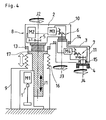
- FIGS. 3 and 4 individually show two examples of the industrial robot (hereinafter referred to simply as robot) of this type.
- the robot has one linear axis J1 and three rotation axes J2, J3 and J4.
- the linear axis J1 is driven for translation by a servomotor M1 with the aid of a ball screw and nut mechanism 1 or the like, and serves to move a second axis arm 2 up and down.
- the rotation axis J2 causes a servomotor M2 to rotate the second axis arm 2 within a horizontal plane through the medium of a speed reducer 5.
- the rotation axis J3 causes a servomotor M3 to rotate a third axis arm 3 within a horizontal plane through the medium of a speed reducer 6.
- the rotation axis J4 causes a servomotor M4 to rotate a working tool 4 within a horizontal plane through the medium of a speed reducer 7.
- An outer wall 8 that covers the robot is composed of a first casing 9 stored with the ball screw and nut mechanism 1, servomotor M1, etc., a second casing 10 stored with the servomotors M2 and M3, speed reducers 5 and 6, etc., and a third casing 11 stored with the servomotor M4, speed reducer 7, etc.
- An oil seal 12 for maintaining dust- and waterproof functions is mounted between the first casing 9 and the linear axis J1 that makes a straight advance with respect to the first casing 9.
- Oil seals 13, 14 and 15 for dust- and waterproof functions are mounted between the second casing 10 and the linear axis J1 that rotates with respect to the second casing 10, between the second casing 10 and the third casing 11 that rotate with respect to the second casing 10, and between the third casing 11 and the rotation axis J4 that rotates with respect to the third casing 11, respectively.
- the second casing 10 and the third casing 11 are independent of each other and of the first casing 9.
- the respective internal pressures of the second and third casings 10 and 11 never fluctuate as the second and third axis arms 2 and 3 rotate. If any one of the oil seals 13, 14 and 15 between the linear axis J1 and the second casing 10, between the second and third casings 10 and 11, and between the third casing 11 and the rotation axis J4 is damaged, the outside air containing dust and moisture inevitably gets into the second or third casing.
- a cylindrical flexible bellows 16 coaxial with a linear axis J1 is mounted between the top surface of a first casing 9 and the undersurface of a top flange portion 17 of the linear axis J1.
- an oil seal 12 such as the one shown in FIG. 3, is not mounted between the first casing 9 and the linear axis J1.
- the robot of FIG. 4 resembles the robot of FIG. 3 in that the pressure in the first casing 9 is caused to fluctuate by the motion of the linear axis J1 of the robot, so that it is encountered by the same problems mentioned before in connection with the robot of FIG. 3.
- the bellows 16 itself is caused repeatedly to expand and contract by the pressure fluctuation in the first casing 9 that is caused by the motion of the linear axis J1, so that it may possibly crack due to degradation of its material.
- the object of the present invention is to provide an outer wall structure of an industrial robot, in which fluctuation of the pressure inside an outer wall can be prevented or reduced so that penetration of dust or water can be prevented or reduced more securely.
- the outer wall and necessary members for sealing the same can be protected from deterioration under pressure load.
- a first aspect of a sealed structure of an industrial robot according to the present invention is arranged so that, in an industrial robot having a sealed outer wall, the outer wall is connected with vessel-shaped internal pressure fluctuation absorbing means having a variable capacity.
- a second aspect of a sealed structure of an industrial robot according to the present invention is arranged so that, in an industrial robot having a sealed outer wall, the outer wall is connected with a gas inlet port through which a compressed gas is fed into the space inside the outer wall and an exhaust mechanism adapted to evacuate or reduce the gas in the space inside the outer wall when the pressure inside the outer wall becomes higher than a set value.
- the present invention penetration of dust or water, attributable to the reduction of the gas pressure inside the outer wall what covers the robot, can be prevented or reduced, and the outer wall and necessary members for sealing it are subjected to a a zero or reduced load attributable to the difference between internal and external pressures, so that the outer wall structure and sealed structure are improved in durability.
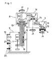
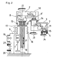
- FIG. 1 A first embodiment of the present invention will be described with reference to FIG. 1.
- An industrial robot (hereinafter referred to simply as robot) has one linear axis J1 and three rotation axes J2, J3 and J4.
- the linear axis J1 is driven in the vertical direction by a servomotor M1 with the aid of a ball screw and nut mechanism 1 or the like, and serves to move a second axis arm 2 up and down.
- the rotation axis J2 causes a servomotor M2 to rotate the second axis arm 2 within a horizontal plane through the medium of a speed reducer 5'.
- the rotation axis J3 causes a servomotor M3 to rotate a third axis arm 3 within a horizontal plane through the medium of a speed reducer 6'.
- the rotation axis J4 causes a servomotor M4 to rotate a working tool 4 within a horizontal plane through the medium of a speed reducer 7.
- An outer wall 8 that covers the robot is composed of a first casing 9 stored with the ball screw and nut mechanism 1, servomotor M1, etc., a second casing 10 stored with the servomotors M2 and M3, speed reducers 5' and 6', etc., and a third casing 11 stored with the servomotor M4, speed reducer 7, etc.
- An oil seal 12 for maintaining dust- and waterproof functions is mounted between the first casing 9 and the linear axis J1. Further, oil seals 13, 14 and 15 for dust- and waterproof functions are mounted between the linear axis J1 and the second casing 10, between the second and third casings 10 and 11, and between the third casing 11 and the rotation axis J4, respectively.
- the respective constructions of the robot shown in FIG. 1 and the outer wall 8 that covers the robot are substantially the same as those of the aforementioned ones shown in FIG. 3. However, they are different from the constructions of the robot and the outer wall 8 shown in FIG. 3 in the following points.
Landscapes
- Engineering & Computer Science (AREA)
- Robotics (AREA)
- Mechanical Engineering (AREA)
- Manipulator (AREA)
Abstract
Description
Claims (10)
- A sealed structure of an industrial robot, wherein the industrial robot has a sealed outer wall, and said outer wall is connected with vessel-shaped internal pressure fluctuation absorbing means having a variable capacity.
- A sealed structure of an industrial robot according to claim 1, wherein said internal pressure fluctuation absorbing means is provided inside said outer wall.
- A sealed structure of an industrial robot according to claim 1, wherein said internal pressure fluctuation absorbing means is located at a distance from the industrial robot and connected to said outer wall by means of a tubular connecting member.
- A sealed structure of an industrial robot, wherein the industrial robot has a sealed outer wall, said outer wall is connected with a gas inlet port through which a compressed gas is fed into the space inside said outer wall and an exhaust mechanism adapted to evacuate or reduce the gas in the space inside said outer wall when the pressure inside said outer wall becomes higher than a set value.
- A sealed structure of an industrial robot according to claim 1, 2 or 3, wherein said outer wall is connected with a gas inlet port through which a compressed gas is fed into the space inside said outer wall and an exhaust mechanism adapted to evacuate or reduce the gas in the space inside said outer wall when the pressure inside said outer wall becomes higher than a set value.
- A sealed structure of an industrial robot, characterized in that a casing of the industrial robot, which substantially covers up a linear axis and a mechanism for driving said linear axis for straight movement, is fitted with a mechanism for adjusting the pressure in said casing in response to fluctuation of the pressure inside said casing caused by the movement of said linear axis.
- A sealed structure of an industrial robot according to claim 6, wherein said mechanism for adjusting the pressure in said casing is a vessel-shaped member having a capacity variable in response to the pressure inside said casing produced by the movement of said linear axis, and fluctuation of the substantial volume of the space inside said casing caused by the movement of said linear axis is absorbed as the member changes the capacity thereof.
- A sealed structure of an industrial robot, characterized in that an outer wall substantially sealing an industrial robot including a linear axis and a rotation axis is fitted with a mechanism for adjusting the pressure inside said outer wall in response to fluctuation of the pressure inside said outer wall caused by the movement of said linear axis.
- A sealed structure of an industrial robot according to claim 8, wherein said outer wall includes a first casing covering the linear axis and a mechanism for driving the same and a second casing connected to the first linear axis by means of an oil seal, the second casing covering a rotation axis and a mechanism for driving the same, said linear axis is formed with a through hole extending in the axial direction thereof, said mechanism for adjusting the pressure inside said outer wall is a mechanism for externally introducing a gas into the space inside the outer wall, and a gas introduced into the first casing by said mechanism is introduced into said second casing through the through hole of said linear axis.
- A sealed structure of an industrial robot according to claim 9, wherein said second casing is further connected with a third casing by means of an oil seal for rotation with respect to said second casing, the third casing covers up a rotation axis and a mechanism for driving the same, and said gas introduced into the second casing flows into the third casing through a passage formed in a speed reducer provided at the junction between the second and third casings.
Applications Claiming Priority (2)
| Application Number | Priority Date | Filing Date | Title |
|---|---|---|---|
| JP3980598A JPH11221789A (en) | 1998-02-06 | 1998-02-06 | Sealed structure of industrial robot |
| JP3980598 | 1998-02-06 |
Publications (2)
| Publication Number | Publication Date |
|---|---|
| EP0934805A2 true EP0934805A2 (en) | 1999-08-11 |
| EP0934805A3 EP0934805A3 (en) | 2000-11-15 |
Family
ID=12563185
Family Applications (1)
| Application Number | Title | Priority Date | Filing Date |
|---|---|---|---|
| EP99300855A Withdrawn EP0934805A3 (en) | 1998-02-06 | 1999-02-05 | Sealed structure of outer wall for industrial robot |
Country Status (2)
| Country | Link |
|---|---|
| EP (1) | EP0934805A3 (en) |
| JP (1) | JPH11221789A (en) |
Cited By (4)
| Publication number | Priority date | Publication date | Assignee | Title |
|---|---|---|---|---|
| DE10348841A1 (en) * | 2003-10-21 | 2005-06-02 | Kuka Roboter Gmbh | Device with relatively rotatable parts and a sealing arrangement |
| EP3067168A4 (en) * | 2013-11-08 | 2016-11-02 | Mitsubishi Heavy Ind Ltd | Manipulator |
| CN109986602A (en) * | 2019-03-28 | 2019-07-09 | 上海发那科机器人有限公司 | A kind of robot water-tight device |
| CN118066486A (en) * | 2024-04-24 | 2024-05-24 | 太原博而硕电子科技有限公司 | Natural gas valve leakage detection device and early warning method |
Families Citing this family (3)
| Publication number | Priority date | Publication date | Assignee | Title |
|---|---|---|---|---|
| JP6218677B2 (en) * | 2014-05-30 | 2017-10-25 | 三菱電機株式会社 | Elastic member |
| FR3119786B1 (en) * | 2021-02-12 | 2023-01-06 | Coron Jean Paul | SCARA-type robot joint, with smooth shaft |
| JP7759779B2 (en) * | 2021-11-30 | 2025-10-24 | ニデックインスツルメンツ株式会社 | Horizontal articulated robot |
Family Cites Families (3)
| Publication number | Priority date | Publication date | Assignee | Title |
|---|---|---|---|---|
| JPS61125791A (en) * | 1984-11-26 | 1986-06-13 | フアナツク株式会社 | Industrial robot of inner-pressure explosion-proof structure |
| JPS61197184A (en) * | 1985-02-25 | 1986-09-01 | フアナツク株式会社 | Dustproof device for robot |
| JPH0557666A (en) * | 1991-08-30 | 1993-03-09 | Mitsubishi Electric Corp | Robot device |
-
1998
- 1998-02-06 JP JP3980598A patent/JPH11221789A/en active Pending
-
1999
- 1999-02-05 EP EP99300855A patent/EP0934805A3/en not_active Withdrawn
Cited By (6)
| Publication number | Priority date | Publication date | Assignee | Title |
|---|---|---|---|---|
| DE10348841A1 (en) * | 2003-10-21 | 2005-06-02 | Kuka Roboter Gmbh | Device with relatively rotatable parts and a sealing arrangement |
| DE10348841B4 (en) * | 2003-10-21 | 2005-12-15 | Kuka Roboter Gmbh | Device with relatively rotatable parts and a sealing arrangement |
| EP3067168A4 (en) * | 2013-11-08 | 2016-11-02 | Mitsubishi Heavy Ind Ltd | Manipulator |
| US9701029B2 (en) | 2013-11-08 | 2017-07-11 | Mitsubishi Heavy Industries, Ltd. | Manipulator |
| CN109986602A (en) * | 2019-03-28 | 2019-07-09 | 上海发那科机器人有限公司 | A kind of robot water-tight device |
| CN118066486A (en) * | 2024-04-24 | 2024-05-24 | 太原博而硕电子科技有限公司 | Natural gas valve leakage detection device and early warning method |
Also Published As
| Publication number | Publication date |
|---|---|
| EP0934805A3 (en) | 2000-11-15 |
| JPH11221789A (en) | 1999-08-17 |
Similar Documents
| Publication | Publication Date | Title |
|---|---|---|
| US7422653B2 (en) | Single-sided inflatable vertical slit valve | |
| JP3649248B2 (en) | Valve actuator | |
| CN101558246B (en) | Apparatus to seal a shaft to a diaphragm actuators | |
| EP1052407B1 (en) | Compact pump | |
| WO2007130957A9 (en) | Double diaphragm actuator | |
| KR930006503B1 (en) | Vibration absorbing structure | |
| US20220040869A1 (en) | Robot | |
| CN1215464A (en) | Valve Actuators with Device Mounting Piping | |
| EP0059599B1 (en) | Valve mechanism for low temperature applications | |
| US5553635A (en) | Microvalve for fluid delivery system | |
| US12605825B2 (en) | Robot | |
| EP0888507B1 (en) | Valve actuator with pliable pressure conversion device | |
| JPH11221789A (en) | Sealed structure of industrial robot | |
| CN110962158A (en) | Heat dissipation system of robot | |
| JPH02296087A (en) | Ultrahigh purity gas flow control valve having closed bellows | |
| WO2022202614A1 (en) | Linear motion mechanism, and horizontal articulated robot | |
| US7011011B2 (en) | Vacuum unit for producing a stroke movement | |
| KR102750078B1 (en) | Outer cover for robot and safety robot including same | |
| US7343848B2 (en) | Self-vacuum arrangement for pneumatic equipment | |
| KR20240116476A (en) | Pressure regulator for compressed gases with adjustable gas pressure sensing assembly | |
| JP2006308009A (en) | Air cylinder drive | |
| JP3016720B2 (en) | Sliding rod structure | |
| CN221662066U (en) | Loading and unloading docking device | |
| KR101872677B1 (en) | The inner pressure adjustable reducer | |
| WO2024254827A1 (en) | Harness protection device for industrial robot |
Legal Events
| Date | Code | Title | Description |
|---|---|---|---|
| PUAI | Public reference made under article 153(3) epc to a published international application that has entered the european phase |
Free format text: ORIGINAL CODE: 0009012 |
|
| AK | Designated contracting states |
Kind code of ref document: A2 Designated state(s): AT BE CH CY DE DK ES FI FR GB GR IE IT LI LU MC NL PT SE |
|
| AX | Request for extension of the european patent |
Free format text: AL;LT;LV;MK;RO;SI |
|
| PUAL | Search report despatched |
Free format text: ORIGINAL CODE: 0009013 |
|
| AK | Designated contracting states |
Kind code of ref document: A3 Designated state(s): AT BE CH CY DE DK ES FI FR GB GR IE IT LI LU MC NL PT SE |
|
| AX | Request for extension of the european patent |
Free format text: AL;LT;LV;MK;RO;SI |
|
| AKX | Designation fees paid | ||
| REG | Reference to a national code |
Ref country code: DE Ref legal event code: 8566 |
|
| STAA | Information on the status of an ep patent application or granted ep patent |
Free format text: STATUS: THE APPLICATION IS DEEMED TO BE WITHDRAWN |
|
| 18D | Application deemed to be withdrawn |
Effective date: 20011115 |