EP0933565A2 - Actuator for operating speed change controlling valve of an automatic speed changer - Google Patents
Actuator for operating speed change controlling valve of an automatic speed changer Download PDFInfo
- Publication number
- EP0933565A2 EP0933565A2 EP98113057A EP98113057A EP0933565A2 EP 0933565 A2 EP0933565 A2 EP 0933565A2 EP 98113057 A EP98113057 A EP 98113057A EP 98113057 A EP98113057 A EP 98113057A EP 0933565 A2 EP0933565 A2 EP 0933565A2
- Authority
- EP
- European Patent Office
- Prior art keywords
- housing
- pipe
- speed change
- controlling valve
- actuator
- Prior art date
- Legal status (The legal status is an assumption and is not a legal conclusion. Google has not performed a legal analysis and makes no representation as to the accuracy of the status listed.)
- Granted
Links
Images


Classifications
-
- F—MECHANICAL ENGINEERING; LIGHTING; HEATING; WEAPONS; BLASTING
- F16—ENGINEERING ELEMENTS AND UNITS; GENERAL MEASURES FOR PRODUCING AND MAINTAINING EFFECTIVE FUNCTIONING OF MACHINES OR INSTALLATIONS; THERMAL INSULATION IN GENERAL
- F16H—GEARING
- F16H61/00—Control functions within control units of change-speed- or reversing-gearings for conveying rotary motion ; Control of exclusively fluid gearing, friction gearing, gearings with endless flexible members or other particular types of gearing
- F16H61/26—Generation or transmission of movements for final actuating mechanisms
- F16H61/28—Generation or transmission of movements for final actuating mechanisms with at least one movement of the final actuating mechanism being caused by a non-mechanical force, e.g. power-assisted
- F16H61/32—Electric motors , actuators or related electrical control means therefor
-
- F—MECHANICAL ENGINEERING; LIGHTING; HEATING; WEAPONS; BLASTING
- F16—ENGINEERING ELEMENTS AND UNITS; GENERAL MEASURES FOR PRODUCING AND MAINTAINING EFFECTIVE FUNCTIONING OF MACHINES OR INSTALLATIONS; THERMAL INSULATION IN GENERAL
- F16H—GEARING
- F16H25/00—Gearings comprising primarily only cams, cam-followers and screw-and-nut mechanisms
- F16H25/18—Gearings comprising primarily only cams, cam-followers and screw-and-nut mechanisms for conveying or interconverting oscillating or reciprocating motions
- F16H25/20—Screw mechanisms
- F16H25/2015—Means specially adapted for stopping actuators in the end position; Position sensing means
Definitions
- the present invention relates to an actuator provided in an automatic speed changer of an automotive vehicle for operating a speed change controlling valve for controlling a speed change mechanism.
- a rotational ratio between a shaft on an engine side and a drive shaft is adjusted by changing a ratio of diameters between a driven pulley and a drive pulley which are connected to each other by a metal belt.
- the diameters of the driven pulley and the drive pulley are continuously changed by changing a width of a belt groove of each pulley.
- the width of the belt groove is changed by moving a drum provided in each pulley. Each drum is moved by a hydraulic circuit, and the speed change controlling valve for controlling the amount of movement thereof is operated by an actuator.
- the present invention is made to solve the problems mentioned above, and an object of the present invention is to provide an actuator for operating a speed change controlling valve of an automatic speed changer which can improve an operational precision and reduce the total size and the weight.
- an actuator for operating a speed change controlling valve of an automatic speed changer adapted to be disposed within a transmission case for receiving a speed change mechanism and the speed change controlling valve for controlling the speed change mechanism, comprising: a stepping motor having an outer casing member made of resin, a motor body provided within the outer casing member and a shaft rotated by the motor body; a housing made of resin and coupled with the outer casing member; a pipe having a proximal end portion disposed within the housing and a distal end portion projecting from the housing, the pipe being reciprocatingly moved in an axial direction of the shaft for operating the speed changing controlling valve; and a conversion mechanism disposed within the housing for translating a rotation of the shaft into a linear motion of the pipe.
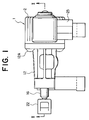
- Fig. 1 is a plan view showing an actuator for operating a speed change controlling valve of an automatic speed changer in accordance with a first embodiment of the present invention
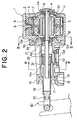
- Fig. 2 is a cross-sectional view taken along a line II-II in Fig. 1
- Fig. 3 is a cross-sectional view taken along a line III-III in Fig. 2
- Fig. 4 is a cross-sectional view taken along a line IV-IV in Fig. 2.
- a PM type stepping motor 1 has an outer casing member 2 made of resin, a motor body 3 provided within the outer casing member 2 and a shaft 4 to be rotated by the motor body 3.
- the motor body 3 has a stator 5 fixed to the outer casing member 2 and a rotor 6 fixed to the shaft 4.
- the stator 5 is provided with a coil 7, a coil terminal 8 drawn from the coil 7 and a connector terminal 9 to which the coil terminal 8 is connected.
- the connector terminal 9 is connected to an external connector 25.
- the rotor 6 is provided wit a bush 10 and a permanent magnet 11.
- a sleeve-like housing 12 made of resin is coupled with the outer casing member 2. Also, a housing 12 is fastened to the outer casing member 2 by a plurality of screws 12A extending in parallel with the shaft 4.
- a circular engagement hole 2a is formed in the outer casing member 2 and an engagement portion 12a inserted into the engagement hole 2a is formed on the housing 12.
- three positioning projections 12b which projected radially and are in contact with an inner circumferential surface of the engagement hole 2a are formed on an outer circumferential surface of the engagement portion 12a.
- an annular groove 12c is formed in the joint surface with the outer casing member 2 of the housing 12.
- a housing communication hole 12d for communicating between the inside and the outside of the housing 12 is provided in the side wall of the housing 12.
- a filter 13 is provided in the housing communication hole 12d for trapping contamination contained in the oil.
- the shaft 4 is rotatably held by bearings 14 and 15.
- the bearing 15 fixed within the housing 12 is of a rubber seal type.
- a pipe 16 that is reciprocating in the axial direction of the shaft 4 by the rotation of the shaft 4 is provided at a tip end portion of the housing 12.
- a proximal end portion of the pipe 16 is inserted into the housing 12, and a distal end portion of the pipe 16 is caused to project from the tip end portion of the housing 12.
- a pipe communication hole 16a for communicating between the interior of the housing 12 and the interior of the pipe 16 is provided in the pipe 16.
- a sleeve 17 for guiding the linear movement of the pipe 16, an oil seal 18 for preventing the contamination of the pipe 16 from the outer circumferential portion and a ring-shaped stopper 19 for limiting the front and rear movement of the pipe 16 are fixed to the inner circumferential surface of the tip end portion of the housing 12.
- a screw portion 4a is provided on the shaft 4.
- a guide member 20 made of resin and engaged with the screw portion 4a is fixed to the proximal end portion of the pipe 16.
- rotation limit projections 20a for limiting the rotation of the pipe 16 are formed to project radially outwardly from the outer circumferential portion of the guide member 20. Accordingly, the guide member 20 is moved in the axial direction of the shaft 4 by the rotation of the shaft 4.
- a stopper 21 made of metal for limiting the rearward movement of the pipe 16 is fixed to the shaft 4.
- the guide member 20 and the stopper 21 have stopper surfaces 20b and 21a which are perpendicular to the rotational direction of the shaft 4, respectively.
- a conversion mechanism 31 has the screw portion 4a, the guide member 20 and the stopper 21.
- the lever 30 is operated by using the stepping motor 1 and the conversion mechanism 31 received in the housing 12, it is possible to improve the operational precision in the oil, and to reduce the total size and the weight.
- the housing 12 is positioned by forming the positioning projections 12b at the engagement portion 12a, if only the precision of the positioning projections 12b is determined with a high precision, even if the outer casing member 2 and the housing 12 are made of resin, it is possible to prevent the displacement of the housing 12 or the tilt of the housing 12 and the pipe 16 to the shaft 4. It is thus possible to perform assembling with a high precision and to reduce the total size and the weight.
- the housing communication hole 12d for communication between the inside and the outside of the housing 12 is formed in the housing 12, even if it is dipped into the oil in the transmission case, the pressure difference generated between the inside and the outside of the housing 12 is suppressed, and the pipe 16 can be moved smoothly. Also, since the filter 13 is provided in the housing communication hole 12d, it is possible to prevent the contamination in the oil from entering the housing 12 and to maintain the smooth motion of the pipe 16.
- the annular groove 12c is formed in the joint surface between the outer casing member 2 and the housing 12, in the case where the oil enters through a slight gap around the joint surface, the contamination can be entrapped by the groove 12c to thereby maintain the normal operation of the stepping motor 1. Also, since the rubber seal type bearing 15 is provided at tee end portion, on the stepping motor 1 side, of the housing 12, it is possible to prevent the contamination from invading from the housing 12 into the motor body 3.
- the operating member 22 is made of resin that is superior in anti-wear property and slidability so that the lever 30 can be stably operated for a long period of time.
- the pipe communication hole 16a for communicating between the interior of the housing 12 and the interior of the pipe 16 is provided in the pipe 16, it is possible to smoothly move the pipe 16 in a linear manner.
- the stopper surfaces 20b and 21a perpendicular to the rotational direction of the shaft 4 are formed on the guide member 20 and the stopper 21, respectively, to thereby limit the rearward movement of the pipe 16, it is possible to maintain the position of the rear end of the pipe 16 more accurately.
- the structure can be simplified. Furthermore, since the resin-made sleeve 17 is fixed within the housing 12 to guide the linear motion of the pipe 16, it is possible to stabilize the linear motion of the pipe 16 with a simple structure.
- the positioning projections 12b are formed on the outer circumferential surface of the engagement portion 12a of the housing 12, but, for example, as shown in Fig. 6, a flat positioning projection 2b may be formed in the inner circumferential surface of the engagement hole 2a of the outer casing member 2. Also, the positioning projection may be formed on both the housing 12 and the outer casing member 2.
- the annular groove 12c is formed in the joint surface of the housing 12 with the outer casing member 2, but, for example, as shown in Fig. 7, 12c and 2c may be formed on both the housing 12 and the outer casing member 2 and the groove may be formed only in the outer casing member 2.
- the advance movement of the pipe 16 is limited by the stopper 19, but, for example, as shown in Fig. 8, the guide member 20 may be brought into contact with the sleeve 17 for guiding the linear motion of the pipe 16 to thereby limit the advance movement of the pipe 16.
Landscapes
- Engineering & Computer Science (AREA)
- General Engineering & Computer Science (AREA)
- Mechanical Engineering (AREA)
- Gear-Shifting Mechanisms (AREA)
- Transmissions By Endless Flexible Members (AREA)
- Control Of Transmission Device (AREA)
Abstract
Description
Claims (10)
- An actuator for operating a speed change controlling valve of an automatic speed changer, adapted to be disposed within a transmission case for receiving a speed change mechanism and the speed change controlling valve for controlling the speed change mechanism, comprising:a stepping motor (1) having an outer casing member (2) made of resin, a motor body (3) provided within said outer casing member (2) and a shaft (4) rotated by said motor body (3);a housing (12) made of resin and coupled with said outer casing member (2);a pipe (16) having a proximal end portion disposed within said housing (12) and a distal end portion projecting from said housing (12), said pipe (16) being reciprocatingly moved in an axial direction of said shaft (4) for operating the speed changing controlling valve; anda conversion mechanism (31) disposed within said housing (12) for translating a rotation of said shaft (4) into a linear motion of said pipe (16).
- An actuator for operating a speed change controlling valve of an automatic speed changer, according to claim 1, wherein an engagement hole (2a) surrounding said shaft (4) is formed in one of said outer casing member (2) and said housing (12), an engagement portion (12a) inserted into said engagement hole (2a) is formed on the other of said outer casing member (2) and said housing (12), and a plurality of positioning projections (12b) projecting radially are formed on at least one of an inner circumferential surface of said engagement hole (2a) and an outer circumferential surface of said engagement portion (12a).
- An actuator for operating a speed change controlling valve of an automatic speed changer, according to claim 1 or 2, wherein said housing (12) is provided with a housing communication hole (12d) for communicating between an interior and an exterior of said housing (12), and a filter (13) is provided in said housing communication hole (12d).
- An actuator for operating a speed change controlling valve of an automatic speed changer, according to claims 1 to 3, wherein an annular groove (12c) is formed in a joint surface between said outer casing member (2) and said housing (12).
- An actuator for operating a speed change controlling valve of an automatic speed changer, according to any one of claims 1 to 4, wherein a rubber seal type bearing (15) for rotatably holding said shaft (4) is provided at an end portion, on a stepping motor side, of said housing (12).
- An actuator for operating a speed change controlling valve of an automatic speed changer, according to any one of claims 1 to 5, wherein a resin-made operating member (22) in engagement with a lever (30) coupled with the speed change controlling valve is mounted at the distal end portion of said pipe (16).
- An actuator for operating a speed change controlling valve of an automatic speed changer, according,to any one of claims 1 to 6, wherein said pipe (16) is formed with a pipe communication hole (16a) for communicating between an interior of said housing (12) and an interior of said pipe (16).
- An actuator for operating a speed change controlling valve of an automatic speed changer, according to any one of claims 1 to 7, wherein said conversion mechanism (31) includes a screw portion (4a) provided at said shaft (4), a guide member (20) threadedly engaged with said screw portion (4a) and fixed to the proximal end portion of said pipe (16) for being moved in the axial direction of said shaft (4) by a rotation of said shaft (4), and a stopper (21) for limiting a rearward movement of said pipe (16), and stopper surfaces (20b) and (21a) perpendicular to a rotational direction of said shaft (4) are formed on said guide member (20) and said stopper (21), respectively.
- An actuator for operating a speed change controlling valve of an automatic speed changer, according to claim 8, wherein a stopper (19) for limiting an advance movement of said pipe (16) by the contact of said guide member (20) is fixed within said housing (12).
- An actuator for operating a speed change controlling valve of an automatic speed changer, according to any one of claims 1 to 9, wherein a resin-made sleeve (17) for guiding a linear motion of said pipe (16) is fixed within said housing (12).
Applications Claiming Priority (2)
| Application Number | Priority Date | Filing Date | Title |
|---|---|---|---|
| JP1883198A JPH11218218A (en) | 1998-01-30 | 1998-01-30 | Actuator for operating shift control valve of automatic transmission |
| JP1883198 | 1998-01-30 |
Publications (3)
| Publication Number | Publication Date |
|---|---|
| EP0933565A2 true EP0933565A2 (en) | 1999-08-04 |
| EP0933565A3 EP0933565A3 (en) | 2001-05-23 |
| EP0933565B1 EP0933565B1 (en) | 2003-03-26 |
Family
ID=11982519
Family Applications (1)
| Application Number | Title | Priority Date | Filing Date |
|---|---|---|---|
| EP98113057A Expired - Lifetime EP0933565B1 (en) | 1998-01-30 | 1998-07-14 | Actuator for operating speed change controlling valve of an automatic speed changer |
Country Status (3)
| Country | Link |
|---|---|
| EP (1) | EP0933565B1 (en) |
| JP (1) | JPH11218218A (en) |
| DE (1) | DE69812576T2 (en) |
Cited By (6)
| Publication number | Priority date | Publication date | Assignee | Title |
|---|---|---|---|---|
| FR2805877A1 (en) * | 2000-03-04 | 2001-09-07 | Luk Lamellen & Kupplungsbau | GEARBOXES |
| DE102005013861B4 (en) * | 2004-03-31 | 2009-11-26 | Jatco Ltd, Fuji | Stepper motor cooling device and associated method for a belt-type continuously variable transmission |
| EP1469236A3 (en) * | 2003-04-18 | 2009-12-23 | Aisin Aw Co., Ltd. | Vehicle running range switching device |
| EP2520829A4 (en) * | 2010-04-26 | 2013-10-23 | Nsk Ltd | LINEAR ACTUATOR |
| DE10145154B4 (en) * | 2000-10-30 | 2015-04-09 | Mitsubishi Denki K.K. | Electromagnetic device |
| DE10137538B4 (en) * | 2000-10-26 | 2025-10-09 | Mitsubishi Denki K.K. | Electromagnetic device |
Families Citing this family (1)
| Publication number | Priority date | Publication date | Assignee | Title |
|---|---|---|---|---|
| JP3723796B2 (en) | 2002-10-11 | 2005-12-07 | 三菱電機株式会社 | Actuator for operation of shift control valve of automatic transmission |
Family Cites Families (6)
| Publication number | Priority date | Publication date | Assignee | Title |
|---|---|---|---|---|
| DE3502222A1 (en) * | 1985-01-24 | 1986-07-24 | WLM Feinwerktechnik GmbH, 5064 Rösrath | Stroke drive having an electric motor |
| IT1232034B (en) * | 1989-03-09 | 1992-01-23 | Rgb Spa | ELECTROMECHANICAL LINEAR ACTUATOR |
| JP3448857B2 (en) * | 1994-05-16 | 2003-09-22 | マツダ株式会社 | Transmission control device for continuously variable transmission |
| JPH08210450A (en) * | 1995-02-01 | 1996-08-20 | Nissan Motor Co Ltd | Line pressure control device for V-belt type continuously variable transmission |
| JPH09247919A (en) * | 1996-03-08 | 1997-09-19 | Minebea Co Ltd | Structure of motor |
| JP3385882B2 (en) * | 1996-11-19 | 2003-03-10 | 日産自動車株式会社 | Hydraulic control device for toroidal type continuously variable transmission |
-
1998
- 1998-01-30 JP JP1883198A patent/JPH11218218A/en active Pending
- 1998-07-14 DE DE1998612576 patent/DE69812576T2/en not_active Expired - Lifetime
- 1998-07-14 EP EP98113057A patent/EP0933565B1/en not_active Expired - Lifetime
Cited By (8)
| Publication number | Priority date | Publication date | Assignee | Title |
|---|---|---|---|---|
| FR2805877A1 (en) * | 2000-03-04 | 2001-09-07 | Luk Lamellen & Kupplungsbau | GEARBOXES |
| DE10137538B4 (en) * | 2000-10-26 | 2025-10-09 | Mitsubishi Denki K.K. | Electromagnetic device |
| DE10145154B4 (en) * | 2000-10-30 | 2015-04-09 | Mitsubishi Denki K.K. | Electromagnetic device |
| EP1469236A3 (en) * | 2003-04-18 | 2009-12-23 | Aisin Aw Co., Ltd. | Vehicle running range switching device |
| DE102005013861B4 (en) * | 2004-03-31 | 2009-11-26 | Jatco Ltd, Fuji | Stepper motor cooling device and associated method for a belt-type continuously variable transmission |
| US7955204B2 (en) | 2004-03-31 | 2011-06-07 | Jatco Ltd | Stepping motor cooling apparatus and method for belt-type continuously variable transmission |
| EP2520829A4 (en) * | 2010-04-26 | 2013-10-23 | Nsk Ltd | LINEAR ACTUATOR |
| US8656798B2 (en) | 2010-04-26 | 2014-02-25 | Nsk Ltd. | Linear actuator |
Also Published As
| Publication number | Publication date |
|---|---|
| DE69812576D1 (en) | 2003-04-30 |
| EP0933565A3 (en) | 2001-05-23 |
| JPH11218218A (en) | 1999-08-10 |
| DE69812576T2 (en) | 2003-12-11 |
| EP0933565B1 (en) | 2003-03-26 |
Similar Documents
| Publication | Publication Date | Title |
|---|---|---|
| CN109863672B (en) | Rotary actuator, rotary drive and shift-by-wire system using the same | |
| EP0911543B1 (en) | Actuator | |
| KR101145579B1 (en) | Compound movement device | |
| EP0933565B1 (en) | Actuator for operating speed change controlling valve of an automatic speed changer | |
| US20150292493A1 (en) | Fluid-pressure pump | |
| WO2020127062A1 (en) | Electric expansion valve | |
| CN104234901A (en) | Starter | |
| KR20040033246A (en) | Actuator for operating a transmission control vlave of an automatic transmission apparatus | |
| EP3564557B1 (en) | Electric actuator | |
| CN101233348B (en) | Automatic transmission | |
| EP3708771B1 (en) | Pump device | |
| JP3622372B2 (en) | Lens drive mechanism | |
| JP3975730B2 (en) | Scroll compressor | |
| US12422040B2 (en) | Gear selection actuator for a shift-by-wire mechanism | |
| CN114857840B (en) | Air door device | |
| JP2000240790A (en) | Positioning structure for manual valve lever | |
| HK1046717B (en) | Magnet pump impeller supporting structure | |
| TWI893934B (en) | Electric actuator | |
| JP2024099977A (en) | Fishing reels | |
| JP2001128413A (en) | Motor with linear drive mechanism | |
| KR100373245B1 (en) | Shift Lever | |
| WO2022030451A1 (en) | Rotary actuator | |
| JP2002139121A (en) | Actuator | |
| JPS62171454A (en) | Stepping motor | |
| JP2008002446A (en) | Drive device for valve lift control device |
Legal Events
| Date | Code | Title | Description |
|---|---|---|---|
| PUAI | Public reference made under article 153(3) epc to a published international application that has entered the european phase |
Free format text: ORIGINAL CODE: 0009012 |
|
| AK | Designated contracting states |
Kind code of ref document: A2 Designated state(s): DE FR GB |
|
| AX | Request for extension of the european patent |
Free format text: AL;LT;LV;MK;RO;SI |
|
| RIC1 | Information provided on ipc code assigned before grant |
Free format text: 7F 16H 61/32 A |
|
| PUAL | Search report despatched |
Free format text: ORIGINAL CODE: 0009013 |
|
| AK | Designated contracting states |
Kind code of ref document: A3 Designated state(s): AT BE CH CY DE DK ES FI FR GB GR IE IT LI LU MC NL PT SE |
|
| AX | Request for extension of the european patent |
Free format text: AL;LT;LV;MK;RO;SI |
|
| 17P | Request for examination filed |
Effective date: 20010502 |
|
| AKX | Designation fees paid |
Free format text: DE FR GB |
|
| 17Q | First examination report despatched |
Effective date: 20020404 |
|
| GRAH | Despatch of communication of intention to grant a patent |
Free format text: ORIGINAL CODE: EPIDOS IGRA |
|
| GRAH | Despatch of communication of intention to grant a patent |
Free format text: ORIGINAL CODE: EPIDOS IGRA |
|
| GRAA | (expected) grant |
Free format text: ORIGINAL CODE: 0009210 |
|
| AK | Designated contracting states |
Designated state(s): DE FR GB |
|
| REG | Reference to a national code |
Ref country code: GB Ref legal event code: FG4D |
|
| REF | Corresponds to: |
Ref document number: 69812576 Country of ref document: DE Date of ref document: 20030430 Kind code of ref document: P |
|
| REG | Reference to a national code |
Ref country code: GB Ref legal event code: 727 |
|
| REG | Reference to a national code |
Ref country code: GB Ref legal event code: 727A |
|
| ET | Fr: translation filed | ||
| REG | Reference to a national code |
Ref country code: GB Ref legal event code: 727B |
|
| PLBE | No opposition filed within time limit |
Free format text: ORIGINAL CODE: 0009261 |
|
| STAA | Information on the status of an ep patent application or granted ep patent |
Free format text: STATUS: NO OPPOSITION FILED WITHIN TIME LIMIT |
|
| 26N | No opposition filed |
Effective date: 20031230 |
|
| REG | Reference to a national code |
Ref country code: FR Ref legal event code: PLFP Year of fee payment: 19 |
|
| REG | Reference to a national code |
Ref country code: FR Ref legal event code: PLFP Year of fee payment: 20 |
|
| PGFP | Annual fee paid to national office [announced via postgrant information from national office to epo] |
Ref country code: FR Payment date: 20170613 Year of fee payment: 20 |
|
| PGFP | Annual fee paid to national office [announced via postgrant information from national office to epo] |
Ref country code: GB Payment date: 20170712 Year of fee payment: 20 Ref country code: DE Payment date: 20170711 Year of fee payment: 20 |
|
| REG | Reference to a national code |
Ref country code: DE Ref legal event code: R071 Ref document number: 69812576 Country of ref document: DE |
|
| REG | Reference to a national code |
Ref country code: GB Ref legal event code: PE20 Expiry date: 20180713 |
|
| PG25 | Lapsed in a contracting state [announced via postgrant information from national office to epo] |
Ref country code: GB Free format text: LAPSE BECAUSE OF EXPIRATION OF PROTECTION Effective date: 20180713 |