EP0933549B1 - Transmission device for rotary motion in steps, in particular in packing machines at high operating speeds - Google Patents
Transmission device for rotary motion in steps, in particular in packing machines at high operating speeds Download PDFInfo
- Publication number
- EP0933549B1 EP0933549B1 EP19990100251 EP99100251A EP0933549B1 EP 0933549 B1 EP0933549 B1 EP 0933549B1 EP 19990100251 EP19990100251 EP 19990100251 EP 99100251 A EP99100251 A EP 99100251A EP 0933549 B1 EP0933549 B1 EP 0933549B1
- Authority
- EP
- European Patent Office
- Prior art keywords
- transmission
- maltese
- spider
- fact
- tumblers
- Prior art date
- Legal status (The legal status is an assumption and is not a legal conclusion. Google has not performed a legal analysis and makes no representation as to the accuracy of the status listed.)
- Expired - Lifetime
Links
- 230000005540 biological transmission Effects 0.000 title claims description 35
- 238000012856 packing Methods 0.000 title claims description 4
- 241000239290 Araneae Species 0.000 claims description 47
- 230000008878 coupling Effects 0.000 claims description 21
- 238000010168 coupling process Methods 0.000 claims description 21
- 238000005859 coupling reaction Methods 0.000 claims description 21
- 244000027321 Lychnis chalcedonica Species 0.000 claims description 8
- 235000019504 cigarettes Nutrition 0.000 claims description 5
- 230000000295 complement effect Effects 0.000 claims description 3
- 230000010355 oscillation Effects 0.000 claims description 2
- 230000002093 peripheral effect Effects 0.000 claims description 2
- 230000009466 transformation Effects 0.000 claims description 2
- 230000008901 benefit Effects 0.000 description 4
- 230000001360 synchronised effect Effects 0.000 description 4
- 230000001133 acceleration Effects 0.000 description 2
- 238000009795 derivation Methods 0.000 description 2
- 238000007789 sealing Methods 0.000 description 2
- 230000009471 action Effects 0.000 description 1
- 238000004026 adhesive bonding Methods 0.000 description 1
- 238000010276 construction Methods 0.000 description 1
- 230000000694 effects Effects 0.000 description 1
- 230000010354 integration Effects 0.000 description 1
- 230000007246 mechanism Effects 0.000 description 1
- 230000003534 oscillatory effect Effects 0.000 description 1
- 230000010363 phase shift Effects 0.000 description 1
- 230000009467 reduction Effects 0.000 description 1
- 230000001131 transforming effect Effects 0.000 description 1
Images

Classifications
-
- F—MECHANICAL ENGINEERING; LIGHTING; HEATING; WEAPONS; BLASTING
- F16—ENGINEERING ELEMENTS AND UNITS; GENERAL MEASURES FOR PRODUCING AND MAINTAINING EFFECTIVE FUNCTIONING OF MACHINES OR INSTALLATIONS; THERMAL INSULATION IN GENERAL
- F16H—GEARING
- F16H27/00—Step-by-step mechanisms without freewheel members, e.g. Geneva drives
- F16H27/04—Step-by-step mechanisms without freewheel members, e.g. Geneva drives for converting continuous rotation into a step-by-step rotary movement
- F16H27/06—Mechanisms with driving pins in driven slots, e.g. Geneva drives
-
- B—PERFORMING OPERATIONS; TRANSPORTING
- B65—CONVEYING; PACKING; STORING; HANDLING THIN OR FILAMENTARY MATERIAL
- B65B—MACHINES, APPARATUS OR DEVICES FOR, OR METHODS OF, PACKAGING ARTICLES OR MATERIALS; UNPACKING
- B65B65/00—Details peculiar to packaging machines and not otherwise provided for; Arrangements of such details
- B65B65/04—Mechanisms for converting a continuous rotary motion to intermittent rotary motion, e.g. Geneva drives
Definitions
- a double tumbler generally of two tumblers oriented diametrically opposite, that is with a phase shift of 180 degrees, allows for keeping the frequency of the steps of advancement, cutting in half the speed of rotation- of the very tumbler and therefore the kinetic energy or the torque of this latter and of the inertial mass of the drive transmission associated with the tumbler.
Landscapes
- Engineering & Computer Science (AREA)
- Mechanical Engineering (AREA)
- General Engineering & Computer Science (AREA)
- Transmission Devices (AREA)
- Transmissions By Endless Flexible Members (AREA)
- Auxiliary Devices For And Details Of Packaging Control (AREA)
- Connection Of Motors, Electrical Generators, Mechanical Devices, And The Like (AREA)
Description
Claims (12)
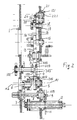
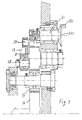
- Transmission device for rotary motion in steps, in particular in the cigarette packing machines at high speed of operation, comprising one input shaft (2), a kinematic chain (3, 4, 5, 6, 7, 8) of transmission of the motion to a spider (9, 209) that carries at least two tumblers (9, 109, 209, 10), which cooperate with a maltese type cross (11), the said maltese type cross is connected dynamically to one or more operative parts (12) to be driven, wherein the spider (9, 209) cooperates with the maltese type cross (11) in the sense that it prevents the rotation in dynamically disengaged condition with one or more tumblers, and wherein a second spider (21, 121, 221) is associated with the maltese type cross (11) characterized by the fact that the second spider is given oscillating or rotary alternating motion between a position of engagement and a position of disengagement with the maltese type cross (11).
- Device according to the claim 1, characterized by the fact that is has a rotary, part (221) with an acxially projecting surface (121) that is shaped in form of a circular segment and that cooperates with corresponding cavities (211) of the maltese type cross (11), which surface presents an angular extension of less than 90 degrees, while the rotary part (221) is activated in oscillating motion around it own axis.
- Device according to the claims 1 and 2, characterized by the fact that the oscillating motion of the second spider (21, 121, 221) is obtained thanks to a transmission of transformation (18, 118, 19, 20, 21) of a monodirectional continuous rotary motion into a alternating rotary motion.
- Device according to one or more of the preceding claims, characterized by the fact that the tumblers (109, 10) are driven in a rotary manner with a transmission (3, 103, 203, 303, 403) that slows down the speed of rotation of the same and therefore the step of advancement of the maltese type cross (11) over a preset angular track within the range of one revolution increasing it over the remaining part of the revolution.
- Device according to claim 4, characterized by the fact that said transmission is formed by a non homokinetic coupling (3).
- Device according to the claim 5, characterized by the fact that between two dynamically linked parts (5, 6) of the kinematic drive chain of the multiple tumbler (109, 10), a coupling (3) is provided with coupling parts (103, 403)- that have a degree of radial freedom and a degree of angular freedom, the two parts (5, 6) of the kinematic chain and the associated parts of the coupling (3) being arranged with their axes of rotation radially staggered between each other.
- Device according to one or more of the preceding claims, characterized by the fact that the coupling (3) comprises a radial arm (3) rotary wise integral with the part (6) of the kinematic chain, which radial arm carries a peripheral roller (203) axially projecting in position of engagement in a radial track (403) and against a radial rib on the other side of the coupling (3) associated with the other part (5) of the kinematic chain.
- Device according to one or more of the preceding claims, characterized by the fact that the alternating rotary motion of the second spider (21, 121, 221) is obtained thanks to a crank type transmission (18, 118, 19, 20, 21), that derives the motion from the kinematic drive chain of the first spider and of the tumblers (9,109, 209, 10).
- Device according to the claim 8, characterized by the fact that the drive transmission with alternating rotary motion or oscillating motion has a drive arm (19) articulated around an eccentric axis (118) on a part (18) rotating in a continuous manner and that is articulated eccentrically (20) relative to the axis of oscillation of the same on the second spider (21, 12, 221), or of the rotary part that forms the same.
- Device according to one or more of the preceding claims, characterized by the fact that it comprises:a) two tumblers carried diametrically opposed, or with a phase of 180 degrees coaxially on the same drive shaft (8) rotating in a continuous manner and engaging in sequence and alternatively between themselves with the maltese cross (11);b) a transmission (3) that gives speeds of rotation different between each other for two diverse and complementary angles of rotation of the drive shaft (8) of the tumblers (109, 10) within the range of one revolution and such, whereby the tumblers rotate slower during the step of advancement of the maltese type cross (11) than during the dwell sequence;e) A transmission for down gearing of the speed of rotation of the tumblers (109, 10) with a preset ratio.
- Device according to the claim 10, characterized by the fact that the ratio of transmission of the down gearing transmission (106, 7) is inverse to the number of tumblers.
- Device according to the claim 11, characterized by the fact that the tumbler is double and the ratio of transmission of the down gearing transmission (106, 7) is such as to halve the number of revolutions.
Applications Claiming Priority (2)
| Application Number | Priority Date | Filing Date | Title |
|---|---|---|---|
| ITSV980005 | 1998-01-28 | ||
| IT1998SV000005A IT1305401B1 (en) | 1998-01-28 | 1998-01-28 | TRANSMISSION DEVICE FOR STEP-BY-STEP ROTARY MOTOR, IN PARTICULAR IN HIGH SPEED PACKAGING MACHINES |
Publications (2)
| Publication Number | Publication Date |
|---|---|
| EP0933549A1 EP0933549A1 (en) | 1999-08-04 |
| EP0933549B1 true EP0933549B1 (en) | 2003-06-11 |
Family
ID=11408256
Family Applications (1)
| Application Number | Title | Priority Date | Filing Date |
|---|---|---|---|
| EP19990100251 Expired - Lifetime EP0933549B1 (en) | 1998-01-28 | 1999-01-08 | Transmission device for rotary motion in steps, in particular in packing machines at high operating speeds |
Country Status (3)
| Country | Link |
|---|---|
| EP (1) | EP0933549B1 (en) |
| DE (1) | DE69908670T2 (en) |
| IT (1) | IT1305401B1 (en) |
Families Citing this family (1)
| Publication number | Priority date | Publication date | Assignee | Title |
|---|---|---|---|---|
| DE102011110251A1 (en) * | 2011-06-03 | 2012-12-06 | Focke & Co. (Gmbh & Co. Kg) | Apparatus for conveying tobacco industry products |
Family Cites Families (4)
| Publication number | Priority date | Publication date | Assignee | Title |
|---|---|---|---|---|
| FR990258A (en) * | 1944-06-08 | 1951-09-19 | Improvement in the Maltese cross device of cinematographic projection devices | |
| GB1212814A (en) * | 1968-07-11 | 1970-11-18 | Gd Societa In Accommandita Sem | Improvements in and relating to geneva wheel devices |
| JPS57137760A (en) * | 1981-02-18 | 1982-08-25 | Toshiba Corp | Geneva gear transmitter |
| IT1281206B1 (en) * | 1995-02-15 | 1998-02-17 | Sasib Spa | CONVEYOR DEVICE ON CIRCULAR ROUTES, IN PARTICULAR FOR GROUPS OF DELICATE ASTIFORMAL OBJECTS AND IN PACKAGING MACHINES |
-
1998
- 1998-01-28 IT IT1998SV000005A patent/IT1305401B1/en active
-
1999
- 1999-01-08 DE DE69908670T patent/DE69908670T2/en not_active Expired - Fee Related
- 1999-01-08 EP EP19990100251 patent/EP0933549B1/en not_active Expired - Lifetime
Also Published As
| Publication number | Publication date |
|---|---|
| DE69908670D1 (en) | 2003-07-17 |
| DE69908670T2 (en) | 2004-04-22 |
| IT1305401B1 (en) | 2001-05-04 |
| ITSV980005A1 (en) | 1999-07-28 |
| EP0933549A1 (en) | 1999-08-04 |
Similar Documents
| Publication | Publication Date | Title |
|---|---|---|
| US8449426B2 (en) | Continuously variable transmission and automobile drive system | |
| US20030047025A1 (en) | Harmonic drive and internal geared wheel for a drive of this type | |
| US3516267A (en) | Mechanism for transforming a unidirectional rotary motion into an oscillating motion | |
| EP0933549A1 (en) | Transmission device for rotary motion in steps, in particular in packing machines at high operating speeds | |
| CA2136327A1 (en) | Planetary gear with two driven shafts | |
| RU2004123883A (en) | FALCES | |
| KR100797544B1 (en) | Gearbox assembly | |
| WO1991010081A1 (en) | Continuously variable transmission | |
| SE464502B (en) | SWITCHING ALTERNATORS WITH STEPLESS TRANSITION OF THE Eccentric Moment | |
| RU2364775C1 (en) | Mechanical transmission | |
| US5699893A (en) | Angular conveyor for fragile cylindrical objects, in cigarette packing machines | |
| JPH03175101A (en) | Oscillating rotary engine | |
| US4549639A (en) | Clutch control for a rotation and reciprocation transmission | |
| KR101510971B1 (en) | Camshaft adjusting apparatus | |
| JPH07508822A (en) | Planetary roller transmission with two rings having internal moldings and one rolling member rolling on the outside of the rings | |
| CN2076187U (en) | Drive structure for rigid harmonic deceleration or angular division | |
| JPS6257447B2 (en) | ||
| JP7829615B2 (en) | Internal rotational motion transmission device | |
| US6272959B1 (en) | Continuously rotating shears | |
| RU2293701C2 (en) | Folding cylinders of folder | |
| EP0933299A1 (en) | Transmission for packaging machines for wrapping cigarettes | |
| JP2915141B2 (en) | Rotating piston machine | |
| CN111577849A (en) | Automatic speed change synchronous pulley box | |
| JPS61153052A (en) | Crank mechanism type continuously variable transmission | |
| KR100392703B1 (en) | Speed reduction apparatus of turning apparatus to arrange turbine rotor |
Legal Events
| Date | Code | Title | Description |
|---|---|---|---|
| PUAI | Public reference made under article 153(3) epc to a published international application that has entered the european phase |
Free format text: ORIGINAL CODE: 0009012 |
|
| AK | Designated contracting states |
Kind code of ref document: A1 Designated state(s): DE FR GB |
|
| AX | Request for extension of the european patent |
Free format text: AL;LT;LV;MK;RO;SI |
|
| 17P | Request for examination filed |
Effective date: 20000208 |
|
| AKX | Designation fees paid |
Free format text: DE FR GB |
|
| RAP1 | Party data changed (applicant data changed or rights of an application transferred) |
Owner name: SASIB S.P.A. |
|
| 17Q | First examination report despatched |
Effective date: 20020731 |
|
| GRAH | Despatch of communication of intention to grant a patent |
Free format text: ORIGINAL CODE: EPIDOS IGRA |
|
| RIC1 | Information provided on ipc code assigned before grant |
Ipc: 7F 16H 27/06 B Ipc: 7F 16D 27/06 A |
|
| GRAH | Despatch of communication of intention to grant a patent |
Free format text: ORIGINAL CODE: EPIDOS IGRA |
|
| GRAA | (expected) grant |
Free format text: ORIGINAL CODE: 0009210 |
|
| AK | Designated contracting states |
Designated state(s): DE FR GB |
|
| REG | Reference to a national code |
Ref country code: GB Ref legal event code: FG4D |
|
| REF | Corresponds to: |
Ref document number: 69908670 Country of ref document: DE Date of ref document: 20030717 Kind code of ref document: P |
|
| ET | Fr: translation filed | ||
| PGFP | Annual fee paid to national office [announced via postgrant information from national office to epo] |
Ref country code: GB Payment date: 20040121 Year of fee payment: 6 |
|
| PGFP | Annual fee paid to national office [announced via postgrant information from national office to epo] |
Ref country code: FR Payment date: 20040129 Year of fee payment: 6 |
|
| PGFP | Annual fee paid to national office [announced via postgrant information from national office to epo] |
Ref country code: DE Payment date: 20040308 Year of fee payment: 6 |
|
| PLBE | No opposition filed within time limit |
Free format text: ORIGINAL CODE: 0009261 |
|
| STAA | Information on the status of an ep patent application or granted ep patent |
Free format text: STATUS: NO OPPOSITION FILED WITHIN TIME LIMIT |
|
| 26N | No opposition filed |
Effective date: 20040312 |
|
| PG25 | Lapsed in a contracting state [announced via postgrant information from national office to epo] |
Ref country code: GB Free format text: LAPSE BECAUSE OF NON-PAYMENT OF DUE FEES Effective date: 20050108 |
|
| PG25 | Lapsed in a contracting state [announced via postgrant information from national office to epo] |
Ref country code: DE Free format text: LAPSE BECAUSE OF NON-PAYMENT OF DUE FEES Effective date: 20050802 |
|
| GBPC | Gb: european patent ceased through non-payment of renewal fee |
Effective date: 20050108 |
|
| PG25 | Lapsed in a contracting state [announced via postgrant information from national office to epo] |
Ref country code: FR Free format text: LAPSE BECAUSE OF NON-PAYMENT OF DUE FEES Effective date: 20050930 |
|
| REG | Reference to a national code |
Ref country code: FR Ref legal event code: ST |