EP0933110A1 - Clarification apparatus for a liquid loaded by flotation - Google Patents
Clarification apparatus for a liquid loaded by flotation Download PDFInfo
- Publication number
- EP0933110A1 EP0933110A1 EP99420019A EP99420019A EP0933110A1 EP 0933110 A1 EP0933110 A1 EP 0933110A1 EP 99420019 A EP99420019 A EP 99420019A EP 99420019 A EP99420019 A EP 99420019A EP 0933110 A1 EP0933110 A1 EP 0933110A1
- Authority
- EP
- European Patent Office
- Prior art keywords
- elements
- liquid
- flotation
- clarified
- tank
- Prior art date
- Legal status (The legal status is an assumption and is not a legal conclusion. Google has not performed a legal analysis and makes no representation as to the accuracy of the status listed.)
- Granted
Links
Images


Classifications
-
- C—CHEMISTRY; METALLURGY
- C02—TREATMENT OF WATER, WASTE WATER, SEWAGE, OR SLUDGE
- C02F—TREATMENT OF WATER, WASTE WATER, SEWAGE, OR SLUDGE
- C02F1/00—Treatment of water, waste water, or sewage
- C02F1/24—Treatment of water, waste water, or sewage by flotation
-
- B—PERFORMING OPERATIONS; TRANSPORTING
- B01—PHYSICAL OR CHEMICAL PROCESSES OR APPARATUS IN GENERAL
- B01D—SEPARATION
- B01D17/00—Separation of liquids, not provided for elsewhere, e.g. by thermal diffusion
- B01D17/02—Separation of non-miscible liquids
- B01D17/0205—Separation of non-miscible liquids by gas bubbles or moving solids
-
- B—PERFORMING OPERATIONS; TRANSPORTING
- B01—PHYSICAL OR CHEMICAL PROCESSES OR APPARATUS IN GENERAL
- B01D—SEPARATION
- B01D17/00—Separation of liquids, not provided for elsewhere, e.g. by thermal diffusion
- B01D17/02—Separation of non-miscible liquids
- B01D17/0208—Separation of non-miscible liquids by sedimentation
- B01D17/0211—Separation of non-miscible liquids by sedimentation with baffles
-
- B—PERFORMING OPERATIONS; TRANSPORTING
- B01—PHYSICAL OR CHEMICAL PROCESSES OR APPARATUS IN GENERAL
- B01D—SEPARATION
- B01D21/00—Separation of suspended solid particles from liquids by sedimentation
- B01D21/0027—Floating sedimentation devices
-
- B—PERFORMING OPERATIONS; TRANSPORTING
- B01—PHYSICAL OR CHEMICAL PROCESSES OR APPARATUS IN GENERAL
- B01D—SEPARATION
- B01D21/00—Separation of suspended solid particles from liquids by sedimentation
- B01D21/0039—Settling tanks provided with contact surfaces, e.g. baffles, particles
- B01D21/0045—Plurality of essentially parallel plates
-
- B—PERFORMING OPERATIONS; TRANSPORTING
- B01—PHYSICAL OR CHEMICAL PROCESSES OR APPARATUS IN GENERAL
- B01D—SEPARATION
- B01D21/00—Separation of suspended solid particles from liquids by sedimentation
- B01D21/0039—Settling tanks provided with contact surfaces, e.g. baffles, particles
- B01D21/0057—Settling tanks provided with contact surfaces, e.g. baffles, particles with counter-current flow direction of liquid and solid particles
-
- B—PERFORMING OPERATIONS; TRANSPORTING
- B01—PHYSICAL OR CHEMICAL PROCESSES OR APPARATUS IN GENERAL
- B01D—SEPARATION
- B01D21/00—Separation of suspended solid particles from liquids by sedimentation
- B01D21/0039—Settling tanks provided with contact surfaces, e.g. baffles, particles
- B01D21/006—Settling tanks provided with contact surfaces, e.g. baffles, particles with co-current flow direction of liquid and solid particles
-
- B—PERFORMING OPERATIONS; TRANSPORTING
- B01—PHYSICAL OR CHEMICAL PROCESSES OR APPARATUS IN GENERAL
- B01D—SEPARATION
- B01D21/00—Separation of suspended solid particles from liquids by sedimentation
- B01D21/24—Feed or discharge mechanisms for settling tanks
-
- B—PERFORMING OPERATIONS; TRANSPORTING
- B01—PHYSICAL OR CHEMICAL PROCESSES OR APPARATUS IN GENERAL
- B01D—SEPARATION
- B01D21/00—Separation of suspended solid particles from liquids by sedimentation
- B01D21/24—Feed or discharge mechanisms for settling tanks
- B01D21/2405—Feed mechanisms for settling tanks
-
- B—PERFORMING OPERATIONS; TRANSPORTING
- B01—PHYSICAL OR CHEMICAL PROCESSES OR APPARATUS IN GENERAL
- B01D—SEPARATION
- B01D21/00—Separation of suspended solid particles from liquids by sedimentation
- B01D21/24—Feed or discharge mechanisms for settling tanks
- B01D21/2427—The feed or discharge opening located at a distant position from the side walls
-
- B—PERFORMING OPERATIONS; TRANSPORTING
- B01—PHYSICAL OR CHEMICAL PROCESSES OR APPARATUS IN GENERAL
- B01D—SEPARATION
- B01D21/00—Separation of suspended solid particles from liquids by sedimentation
- B01D21/24—Feed or discharge mechanisms for settling tanks
- B01D21/2433—Discharge mechanisms for floating particles
-
- B—PERFORMING OPERATIONS; TRANSPORTING
- B01—PHYSICAL OR CHEMICAL PROCESSES OR APPARATUS IN GENERAL
- B01D—SEPARATION
- B01D21/00—Separation of suspended solid particles from liquids by sedimentation
- B01D21/24—Feed or discharge mechanisms for settling tanks
- B01D21/2444—Discharge mechanisms for the classified liquid
Definitions
- FIG. 3A schematically represents the principle of the device according to the invention in the case of clarification by flotation with entry of the liquid to be clarified between the elements in the shape of a "U” and outlet of the liquid clarify inside at the bottom of the elements.
- One or more parallel plates (13, 14) can be installed between the elements (figure 4.). Similarly, one or more parallel plates (15, 16) can be installed inside the elements (figure 4). These plates are also positioned parallel to the constituent branches of the elements (11), and are intended to reduce the any transverse turbulence likely to occur at the entrance or between the elements (11), and to better direct the flows.
- the main dimensions of the clarifier described in connection with FIGS. 6A and 6B can be in the following order of magnitude: total length 3 m total width 2.5m total height 3 m.
Abstract
Description
L'invention concerne un dispositif de clarification par flottation lamellaire. Le dispositif selon l'invention peut être utilisé pour accélérer la séparation des matières en suspension, ci-après désignées par le sigle MES, contenues dans un liquide, et ce par flottation naturelle, si leur densité est inférieure à celle du liquide. Il peut être également utilisé en association avec la technique de la flottation à air dissous. Dans ces deux applications la construction et le principe de fonctionnement du dispositif selon l'invention demeurent les mêmes.The invention relates to a clarification device by lamellar flotation. The device according to the invention can be used to accelerate the separation of materials into suspension, hereinafter designated by the acronym MES, contained in a liquid, and this by natural flotation, if their density is lower than that of the liquid. It can also be used in combination with the technique of dissolved air flotation. In these two applications the construction and the operating principle of the device according to the invention remain the same.
L'appellation courante de ce type de clarificateurs, utilisant la flottation et la technique lamellaire est flottateur à plaques inclinées ou flottateur lamellaire.The common name for this type of clarifier, using flotation and lamellar technique is inclined plate float or lamellar float.
Le procédé et le dispositif décrits sont particulièrement destinés à accélérer la séparation des matières en suspension d'un effluent liquide.The method and the device described are particularly intended to accelerate the separation of suspended matter from a liquid effluent.
Les dispositifs existants de ce type utilisent les techniques suivantes :
Cette technique est utilisée pour accélérer la séparation des MES d'un liquide lorsque la densité des MES est différente de celle du liquide. Si la densité des MES est inférieure à celle du liquide, on parle de clarification lamellaire par flottation. La théorie fondamentale de la séparation lamellaire et les avantages de cette technique ne seront pas décrites dans la présente, car considérés comme connus.
Cette technique est souvent associée à la technique de la séparation lamellaire. Elle consiste à utiliser la propriété de microbulles d'air (ou bien d'un autre gaz), produites par un dispositif approprié, propriété qui réside dans la capacité de ces microbulles d'adhérer aux particules, c'est à dire aux matières en suspension, présentes dans le liquide, et de les entraíner à la surface du liquide. Dans ce cas on parle d'une flottation forcée.
This technique is used to accelerate the separation of MES from a liquid when the density of MES is different from that of the liquid. If the density of the MES is lower than that of the liquid, we speak of lamellar clarification by flotation. The fundamental theory of lamellar separation and the advantages of this technique will not be described herein, since they are considered to be known.
This technique is often associated with the technique of lamellar separation. It consists in using the property of microbubbles of air (or of another gas), produced by an appropriate device, property which resides in the capacity of these microbubbles to adhere to particles, that is to say suspension, present in the liquid, and entrain them on the surface of the liquid. In this case we speak of a forced flotation.
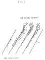
Le principe de la séparation lamellaire par flottation des MES du liquide va être sommairement décrit ci-après, à l'appui des figures 1 et 2A - 2C : The principle of lamellar separation by flotation of the MES from the liquid will be briefly described below, in support of Figures 1 and 2A - 2C:
Il convient préalablement de préciser, que dans le cas de l'utilisation de la technique de la flottation à air dissous, le dispositif de production de microbulles d'air nécessaire à la flottation n'est pas décrit dans la présente, car considéré comme connu. Il est simplement supposé que les MES à séparer du liquide ont une densité inférieure à celle du liquide ou bien qu'elles sont «allégées» par des microbulles et donc qu'elles flottent.It should be specified beforehand, that in the case of the use of the technique of dissolved air flotation, the microbubble production device necessary for the flotation is not described herein, as it is considered to be known. It is simply assumed that the MES to be separated from the liquid have a density lower than that of the liquid or although they are "lightened" by microbubbles and therefore they float.
Le liquide chargé en matières flottantes est introduit entre les plaques inclinées (1) appelées aussi lamelles (figure 1). Les matières flottantes représentées sur les différentes figures par des petits cercles, remontent vers le haut jusqu'à ce qu'elles atteignent la surface de la plaque supérieure desdites lamelles. Ensuite elles remontent en glissant le long de la plaque constitutive de chacune des lamelles dans le sens de la flèche représentée en traits mixtes (2) jusqu'à l'extrémité supérieure de chacune desdites lamelles. Arrivées à ce stade, les matières flottantes se détachent de la plaque et remontent vers la surface du liquide. La place occupée par les particules, et donc libérée est prise par le liquide clarifié, qui «glisse» le long de la surface de la plaque inférieure dans le sens de la flèche (3), c'est à dire dans un sens opposé à celui de la remontée des matières flottantes, c'est à dire du haut vers le bas. Ainsi le liquide clarifié et les matières flottantes se croisent entre deux plaques pour se séparer: les matières flottantes vers le haut et le liquide clarifié vers le bas.The liquid loaded with floating materials is introduced between the inclined plates (1) also called lamellae (Figure 1). The floating materials represented on the different figures by small circles, go up until they reach the surface of the upper plate of said strips. Then they go up by sliding the along the constituent plate of each of the lamellae in the direction of the arrow shown in phantom (2) to the upper end of each of said slats. At this stage, the floating materials detach from the plate and rise towards the surface of the liquid. The space occupied by the particles, and therefore freed, is taken by the clarified liquid, which "slides" along the surface of the bottom plate in the direction of the arrow (3), that is to say in a direction opposite to that of the lifting of the materials floating, i.e. from top to bottom. So clarified liquid and floating matter intersect between two plates to separate: the materials floating upwards and the liquid clarified down.
En fonction du sens du flux d'introduction du liquide à clarifier par rapport aux
lamelles, il existe trois types de clarificateurs lamellaires:
- Afin d'augmenter la Surface Totale Projetée (STP) et donc la capacité de séparation
du flottateur pour la même surface au sol, il s'avère nécessaire de ;
- diminuer la distance entre les lamelles; cependant plus cette distance est faible, plus le frottement entre le voile de matières flottantes qui remontent et le flux du liquide clarifié qui descend est important, ce qui perturbe la remontée des matières flottantes;
- d'augmenter la hauteur des lamelles pour pouvoir augmenter la vitesse de passage entre les lamelles ; en réalité la hauteur des lamelle dépend de la quantité de MES à évacuer et de la compactibilité du voile de matières flottantes. Les lamelles trop hautes sont facilement engorgées en partie haute par un voile de matières flottantes trop important ;
- Dans l'espace situé au dessus des lamelles, les matières flottantes concentrées entre les lamelles entrent en contact avec le liquide à clarifier. Par conséquent elles sont rediluées par le liquide et une partie d'entre elles est de nouveau entraínée par le liquide entre les lamelles, ce qui diminue l'efficacité de la séparation.
- la vitesse de flottation des particules: plus la vitesse augmente et plus la vitesse ascensionnelle limite du flottateur lamellaire se rapproche de celle du flottateur à flux vertical;
- la concentration en MES : plus elle augmente et plus la vitesse ascensionnelle limite du flottateur lamellaire diminue par rapport à celle du flottateur à flux vertical;
- la compactibilité du voile de matières flottantes: plus les matières flottantes se compactent facilement, et plus la vitesse ascensionnelle limite du flottateur lamellaire se rapproche de celle du flottateur à flux vertical.
- In order to increase the Total Projected Area (STP) and therefore the separation capacity of the float for the same floor area, it is necessary to;
- decrease the distance between the slats; however, the smaller this distance, the greater the friction between the veil of floating materials which rise and the flow of the clarified liquid which descends, which disturbs the rise of the floating materials;
- increasing the height of the slats in order to be able to increase the speed of passage between the slats; in reality the height of the slats depends on the quantity of MES to be removed and on the compactibility of the veil of floating materials. The too high slats are easily engorged in the upper part by a veil of floating material that is too large;
- In the space above the coverslips, the floating matter concentrated between the coverslips comes into contact with the liquid to be clarified. Therefore they are diluted by the liquid and part of them is again entrained by the liquid between the lamellae, which reduces the efficiency of the separation.
- the flotation speed of the particles: the more the speed increases, the more the limiting ascending speed of the lamellar float approaches that of the vertical flow float;
- the MES concentration: the more it increases, the more the limit ascending speed of the lamellar float decreases compared to that of the vertical flow float;
- the compactibility of the veil of floating materials: the more easily the floating materials compact, the more the limiting ascending speed of the lamellar float approaches that of the vertical flow float.
A titre indicatif dans le cas de la clarification par flottation à air dissous d'effluents aqueux, la vitesse maximale théorique de flottation se situe aux environs de 18 m/h. Dans la pratique les flottateurs à flux vertical sont limités à environ 8 m/h pour les constructions les plus évoluées, alors que certains constructeurs de flottateurs lamellaires se limitent à une vitesse ascensionnelle limite Va de 2 m/h seulement, à cause essentiellement des contraintes hydrauliques mentionnées ci-dessus.For information in the case of clarification by dissolved air flotation of effluents aqueous, the theoretical maximum flotation speed is around 18 m / h. In in practice, vertical flow floaters are limited to approximately 8 m / h for most advanced constructions, while some manufacturers of lamellar flotation units are limited to a limit ascending speed Va of only 2 m / h, because essentially the hydraulic constraints mentioned above.
Il ressort de ces différents constats, que la clarification à co-courant permet de séparer rapidement des quantités importantes de MES, mais en revanche, de n'aboutir qu'à une clarification grossière. A contrario, la clarification à contre-courant donne de bons résultats pour des quantités de MES relativement réduites, et permet d'aboutir à une clarification de bonne qualité. Néanmoins, ce mode de clarification est fortement influencé par la concentration en MES dans l'effluent à traiter.It emerges from these various observations, that co-current clarification makes it possible to quickly separate large quantities of MES, but on the other hand, do not succeed only to a gross clarification. Conversely, counter-current clarification gives good results for relatively small quantities of MES, and makes it possible to obtain a good quality clarification. However, this mode of clarification is strongly influenced by the MES concentration in the effluent to be treated.
L'objet de l'invention est de mettre en oeuvre un clarificateur du type en question, susceptible d'utiliser les deux techniques dans les meilleures conditions pour chacune d'entre elles, respectivement à co-courant et à contre-courant, tout en s'affranchissant des inconvénients rappelés ci-dessus, et partant, en optimisant leurs capacités de séparation des matières solides en suspension dans un liquide.The object of the invention is to use a clarifier of the type in question, likely to use both techniques in the best conditions for each of them, respectively co-current and counter-current, while overcoming disadvantages recalled above, and therefore, by optimizing their separation capacities solids suspended in a liquid.
Ce clarificateur comporte une pluralité d'éléments en forme de « U » immergés dans la cuve du clarificateur, lesdits éléments étant disposés sensiblement parallèlement les uns aux autres et séparés selon une certaine distance les uns par rapport aux autres, et inclinés par rapport à l'horizontal, la partie ouverte du «U» étant dirigée vers le haut, chacun desdits éléments recevant en outre au voisinage de son fond un collecteur d'entrée ou de sortie.This clarifier comprises a plurality of U-shaped elements immersed in the clarifier tank, said elements being arranged substantially parallel to each other to each other and separated by a certain distance from each other, and inclined with respect to the horizontal, the open part of the "U" being directed upwards, each said elements further receiving in the vicinity of its bottom an inlet manifold or exit.
La manière dont l'invention peut être réalisée et les avantages qui en découlent, ressortiront mieux des exemples de réalisation qui suivent, donnés à titre indicatif et non limitatif, à l'appui des figures annexées.The manner in which the invention can be carried out and the advantages which flow therefrom, The following examples of embodiment will emerge more clearly, given as an indication and not limiting, in support of the appended figures.
La figure 1 représente schématiquement le principe général de la séparation lamellaire par flottation.Figure 1 shows schematically the general principle of separation lamellar by flotation.
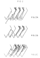
Les figures 2A, 2B et 2C représentent schématiquement les trois types de clarification lamellaire par flottation en fonction du sens d'introduction du liquide à clarifier. FIGS. 2A, 2B and 2C schematically represent the three types of lamellar clarification by flotation as a function of the direction of introduction of the liquid to clarify.
La figure 3A représente schématiquement le principe du dispositif selon l'invention dans le cas d'une clarification par flottation avec entrée du liquide à clarifier entre les éléments en forme de « U » et sortie du liquide clarifier à l'intérieur au fond des éléments.FIG. 3A schematically represents the principle of the device according to the invention in the case of clarification by flotation with entry of the liquid to be clarified between the elements in the shape of a "U" and outlet of the liquid clarify inside at the bottom of the elements.
La figure 3B représente schématiquement le principe du dispositif selon l'invention dans le cas d'une clarification par flottation avec entrée du liquide à clarifier à l'intérieur au fond des éléments en forme de « U »et sortie du liquide à clarifier entre les éléments.FIG. 3B schematically represents the principle of the device according to the invention in the case of clarification by flotation with entry of the liquid to be clarified inside at the bottom of the U-shaped elements and outlet of the liquid to be clarified between the elements.
La figure 3C représente schématiquement un principe analogue à celui décrit dans la figure 3A, mais avec une colonne d'éléments en forme de « U » verticale.FIG. 3C schematically represents a principle analogous to that described in the Figure 3A, but with a column of vertical U-shaped elements.
La figure 3D représente schématiquement un principe analogue à celui décrit dans la figure 3B, mais dans ce cas la rangée d'éléments en forme de « U » est verticale.Figure 3D schematically represents a principle similar to that described in Figure 3B, but in this case the row of U-shaped elements is vertical.
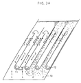
La figure 4. montre quelques éléments optionnels pouvant être associés au dispositif selon l'invention.Figure 4. shows some optional elements that can be associated with the device according to the invention.
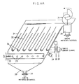
La figure 5A montre un élément selon l'invention sans cloisons latérales. Dans ce cas ce sont les parois de la cuve du clarificateur qui referment l'élément en « U » des deux côtés.FIG. 5A shows an element according to the invention without lateral partitions. In this case it is the walls of the clarifier tank which close the U-shaped element of the two sides.
La figure 5B montre un élément selon l'invention avec cloisons latérales intégrées à l'élément en forme de « U ».FIG. 5B shows an element according to the invention with lateral partitions integrated into the U-shaped element.
La figure 6A représente une vue schématique en coupe longitudinale d'un appareil de clarification par flottation équipé du dispositif selon l'invention, avec une rangée horizontale d'éléments en forme de « U ».FIG. 6A represents a schematic view in longitudinal section of an apparatus clarification by flotation equipped with the device according to the invention, with a row horizontal of U-shaped elements.
La figure 6B représente une vue schématique en coupe transversale de l'appareil montré sur la figure 6A.Figure 6B shows a schematic cross-sectional view of the apparatus shown in Figure 6A.
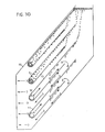
La figure 7A représente une vue schématique en coupe longitudinale d'un autre forme de réalisation de l'appareil de clarification par flottation équipé du dispositif selon l'invention, avec une configuration verticale des éléments en forme de « U ».FIG. 7A represents a schematic view in longitudinal section of another embodiment of the flotation clarification apparatus equipped with the device according to the invention, with a vertical configuration of the U-shaped elements.
La figure 7B représente une vue schématique en coupe transversale de l'appareil montré sur la figure 7A.Figure 7B shows a schematic cross-sectional view of the apparatus shown in Figure 7A.
La figure 7C représente une vue schématique en coupe longitudinale d'une variante de l'appareil montré sur la figure 7A.FIG. 7C represents a schematic view in longitudinal section of a variant of the apparatus shown in Figure 7A.
Le dispositif selon l'invention permet de mettre en oeuvre simultanément deux techniques de séparation lamellaire par flottation, fonctionnat respectivement à co-courant et ensuite à contre-courant. The device according to the invention makes it possible to simultaneously implement two lamellar separation techniques by flotation, co-current function respectively and then against the current.
Selon une première caractéristique de l'invention, le clarificateur comporte plusieurs (au moins deux) éléments en forme de « U » (11), inclinés selon un angle a par rapport à l'horizontale, et immergés dans la cuve (10), tel qu'on peut bien l'observer sur les figures 3A - 3D, et donc positionnés sous la surface du liquide. Chaque élément (11) est équipé d'un collecteur (12) placé au fond de l'élément du côté de son extrémité fermée. Ces collecteurs sont typiquement constitués d'un élément tubulaire, ouvert le long de l'une de ses génératrices Les éléments (11) sont disposés en rangée à une certaine distance les uns des autres.According to a first characteristic of the invention, the clarifier comprises several (at least two) U-shaped elements (11), inclined at an angle a by relative to the horizontal, and immersed in the tank (10), as can be seen on Figures 3A - 3D, and therefore positioned under the surface of the liquid. Each element (11) is equipped with a collector (12) placed at the bottom of the element on the side of its closed end. These collectors typically consist of a tubular element, open along one of its generators The elements (11) are arranged in a row at a certain distance one another.
La distance séparant les deux branches de chacun des éléments (11) est choisie de telle sorte qu'elle soit suffisante pour permettre une séparation entre les matières flottantes (5) et le liquide clarifié. Il est en outre précisé que, même si la distance séparant deux éléments (11) successifs n'est pas nécessairement égale à la distance séparant les deux branches d'un même élément, elle est néanmoins choisie de telle sorte qu'elle remplisse la même condition, c'est à dire être suffisante pour permettre une séparation entre les matière flottantes (5) et le liquide clarifié. A titre indicatif, dans la pratique la distance entre les branches ou plaques des éléments en forme de « U » (11) est comprise entre 5 et 15 cm.The distance separating the two branches of each of the elements (11) is chosen from such that it is sufficient to allow separation between floating material (5) and the clarified liquid. It is further specified that, even if the distance separating two successive elements (11) is not necessarily equal to the distance separating the two branches of the same element, it is nevertheless chosen so that it fulfills the same condition, i.e. be sufficient to allow separation between materials floating (5) and the clarified liquid. As an indication, in practice the distance between the branches or plates of the U-shaped elements (11) is between 5 and 15 cm.
Ainsi qu'on peut bien l'observer sur les figures, ces éléments peuvent se présenter selon une configuration en rangée horizontale (figure 3A, 3B), en colonne verticale (figure 3C, 3D) ou encore en colonne verticale avec décalage horizontale d'un élément au suivant (figure 7C).As can be seen in the figures, these elements can appear in a horizontal row configuration (Figure 3A, 3B), in a vertical column (Figure 3C, 3D) or in a vertical column with horizontal offset from one element to the next (Figure 7C).
L'extrémité fermée de chacun des éléments (11) est disposée en bas, et l'extrémité ouverte en haut.The closed end of each of the elements (11) is arranged at the bottom, and the end open at the top.
Le dispositif selon l'invention peut fonctionner dans deux configurations différentes:The device according to the invention can operate in two configurations different:
Le liquide à clarifier est introduit dans l'espace situé à l'extérieur des éléments (11) du côté de leur extrémité fermée. Il pénètre entre les éléments (11) dans le sens de la flèche (4) jusqu'à atteindre la partie inférieur des éléments (11). Entre lesdits éléments (11), les matières flottantes (5) remontent jusqu'à toucher la paroi extérieure inférieure des éléments (11) et ensuite glissent vers le haut le long de ladite paroi. Arrivées à l'extrémité supérieure des éléments (11), les matières flottantes sont évacuées vers la surface du liquide située au dessus des éléments (11). Le liquide (entièrement ou partiellement clarifié) remonte également du bas vers le haut dans le sens de la flèche (3). Dans cette partie du parcours du liquide la clarification s'effectue selon le principe « à co-courant ». Ensuite le liquide (entièrement ou partiellement clarifié) descend à l'intérieur de chaque élément (11) du haut vers le bas dans le sens de la flèche (3), où une deuxième séparation s'effectue selon le principe « à contre courant ». Les matières flottantes (5) remontent le long de la paroi supérieure desdits éléments, mais à l'intérieur de chacun d'eux, selon le sens de la flèche (2). Le liquide clarifié est collecté au fond de chaque élément (11) par le collecteur (12) dont il est muni, et est évacué de la cuve du clarificateur (10).The liquid to be clarified is introduced into the space located outside the elements (11) on the side of their closed end. It enters between the elements (11) in the direction of the arrow (4) until reaching the lower part of the elements (11). Between said elements (11), the floating materials (5) rise up to touch the lower outer wall of the elements (11) and then slide upwards along said wall. Arrivals at the end upper elements (11), the floating materials are discharged towards the surface of the liquid located above the elements (11). Liquid (fully or partially clarified) also goes up from the bottom up in the direction of the arrow (3). In this part of the liquid path clarification is carried out according to the “co-current” principle. Then the liquid (fully or partially clarified) descends inside each element (11) from top to bottom in the direction of the arrow (3), where a second separation is carried out according to the “against the current” principle. Floating materials (5) go up along the upper wall of said elements, but inside each from them, in the direction of the arrow (2). The clarified liquid is collected at the bottom of each element (11) by the collector (12) with which it is provided, and is discharged from the tank of the clarifier (10).
Le liquide à clarifier est introduit dans la cuve (10) à l'intérieur de chaque élément (11) par le biais du collecteur (12). Il remonte à l'intérieur des éléments (11) depuis le bas vers le haut dans le sens de la flèche (4) jusqu'à atteindre la partie supérieure desdits éléments. A l'intérieur des éléments (11), les matières flottantes (5) remontent jusqu'à atteindre la paroi intérieure supérieure des éléments (11), et ensuite glissent le long de ladite paroi. Arrivées à l'extrémité supérieure des éléments (11), les matières flottantes sont évacuées vers la surface du liquide située au dessus des éléments (11). Le liquide (entièrement ou partiellement clarifié) remonte également du bas vers le haut dans le sens de la flèche (3). Dans cette partie du parcours du liquide la clarification s'effectue selon le principe « à co-courant ».The liquid to be clarified is introduced into the tank (10) inside each element (11) through the manifold (12). It goes up inside the elements (11) from the bottom upwards in the direction of the arrow (4) until reaching the upper part of said elements. Inside the elements (11), the floating materials (5) rise up to reach the upper inner wall of the elements (11), and then slide along said wall. Arrived at the upper end of the elements (11), the floating materials are discharged to the liquid surface located above the elements (11). The liquid (fully or partially clarified) also goes up from bottom to top in the direction arrow (3). In this part of the course of the liquid the clarification is carried out according to the "co-current" principle.
Ensuite le liquide (entièrement ou partiellement clarifié) descend entre les éléments (11) du haut vers le bas dans le sens de la flèche (3), où une seconde séparation s'effectue selon le principe « à contre courant ». Les matières flottantes (5) remontent le long de la paroi inférieure extérieure de chaque élément dans le sens de la flèche (2). Le liquide clarifié est collecté dans l'espace situé du côté ou en dessous de l'extrémité fermée des éléments (11) pour être évacué de la cuve (10) du clarificateur.Then the liquid (fully or partially clarified) descends between the elements (11) from top to bottom in the direction of the arrow (3), where a second separation takes place according to the "against the current" principle. The floating materials (5) go up along the outer bottom wall of each element in the direction of arrow (2). The liquid clarified is collected in the space located on the side or below the closed end of the elements (11) to be evacuated from the tank (10) of the clarifier.
Le fonctionnement du dispositif de clarification selon l'invention est étroitement lié
à la construction et à la mise en oeuvre des éléments en forme de « U » (11). Le côté fermé
des éléments est systématiquement positionné du côté de l'arrivée du liquide à clarifier. Le
fond des éléments est positionné en bas et le côté ouvert en haut, ainsi que déjà dit.
L'espace situé à l'intérieur des éléments (11) est délimité verticalement par les deux parois
inclinées qui constituent les branches du « U », et latéralement soit par les deux parois
opposée de la cuve du clarificateur (10), soit par des parois incorporés à l'élément. De
cette façon chaque élément renferme un espace vers lequel le seul accès est par le coté
ouvert situé au dessus desdits éléments. Cette disposition des éléments du dispositif selon
l'invention permet de faire circuler le liquide entre les éléments du bas vers le haut et
ensuite à l'intérieur de chaque élément (11) du haut vers le bas selon la configuration 1
présentée sur les figures 3A et 3D. Selon la configuration 2 présentée sur les figures 3B et
3D, le liquide circule d'abord à l'intérieur des éléments du bas vers le haut et ensuite entre
les éléments du haut vers le bas.The operation of the clarification device according to the invention is closely linked
the construction and implementation of the U-shaped elements (11). The closed side
elements are systematically positioned on the side of the arrival of the liquid to be clarified. The
bottom of the elements is positioned at the bottom and the open side at the top, as already mentioned.
The space inside the elements (11) is delimited vertically by the two walls
inclined which constitute the branches of the "U", and laterally either by the two walls
opposite from the clarifier tank (10), or by walls incorporated into the element. Of
this way each element contains a space to which the only access is by the side
open located above said elements. This arrangement of the elements of the device according to
the invention makes it possible to circulate the liquid between the elements from the bottom to the top and
then inside each element (11) from top to bottom according to
Quelle que soit la configuration mise en oeuvre, il s'agit du même dispositif utilisant le même procédé de clarification. Le dispositif de clarification selon l'invention peut donc fonctionner dans les deux sens.Whatever the configuration used, it is the same device using the same clarification process. The clarification device according to the invention can therefore work both ways.
La mise en oeuvre des éléments inclinés en forme de « U » peut être réalisée de
plusieurs façons : ils peuvent être fixés sur la cuve du clarificateur (10) (figures 3A, 3B,
3C, 3D). Chaque élément (11) peut être fixé indépendamment dans la cuve du
clarificateur (10). Le cas échéant, deux ou plusieurs éléments (11) peuvent former un
bloc. Les éléments 11 peuvent également être supportés par un support extérieur à la cuve
du clarificateur.The implementation of inclined elements in the shape of a "U" can be carried out
several ways: they can be fixed on the clarifier tank (10) (Figures 3A, 3B,
3C, 3D). Each element (11) can be fixed independently in the tank of the
clarifier (10). If necessary, two or more elements (11) can form a
block. The
En outre, les éléments en forme de « U » (11) peuvent adopter une configuration horizontale, dans laquelle ils sont orientés parallèlement les uns aux autres à la même hauteur au sein de la cuve (10) (figures 3A, 3B, 6A). Ils peuvent également adopter une configuration verticale, dans laquelle ils sont orientés parallèlement les uns aux autres et les uns au dessus des autres (figures 3C, 3D, 7A). Enfin, ils peuvent adopter une configuration dite inclinée, dans laquelle ils sont orientés parallèlement les uns aux autres et les uns au dessus des autres, tout en présentant un certain décalage selon une droite inclinée (figure 7C).Quelle que soit la configuration retenue, le côté fermé de chaque élément reste toujours en dessous par rapport à son côté ouvert.In addition, the U-shaped elements (11) can adopt a configuration horizontal, in which they are oriented parallel to each other at the same height within the tank (10) (Figures 3A, 3B, 6A). They can also adopt a vertical configuration, in which they are oriented parallel to each other and one above the other (Figures 3C, 3D, 7A). Finally, they can adopt a so-called inclined configuration, in which they are oriented parallel to each other and one above the other, while presenting a certain offset along a straight line inclined (Figure 7C) .Whatever the configuration chosen, the closed side of each element always remains below relative to its open side.
Les éléments (11) peuvent être réalisés en métal, plastique, toile, céramique, ou tout autre matériau plat ou profilé, rigide ou souple. Le cas échéants les éléments (11) peuvent être constitués de plusieurs parties différentes formant un ensemble.The elements (11) can be made of metal, plastic, canvas, ceramic, or any other flat or profiled material, rigid or flexible. Where applicable, elements (11) may consist of several different parts forming a whole.
Les parois de chaque élément (11) peuvent être droites ou courbes, parallèles ou non parallèles. Les parois de chaque élément peuvent avoir la même longueur ou des longueurs différentes (sur figure 4. ; L1 = L2 ou bien L1 < L2 ou encore L1 > L2)The walls of each element (11) can be straight or curved, parallel or non-parallel. The walls of each element can have the same length or different lengths (in Figure 4.; L 1 = L 2 or else L 1 <L 2 or even L 1 > L 2 )
Une ou plusieurs plaques parallèles (13, 14) peuvent être installées entre les éléments (figure 4.). De même, une ou plusieurs plaques parallèles (15, 16) peuvent être installées à l'intérieur des éléments (figure 4). Ces plaques sont positionnées également parallèlement aux branches constitutives des éléments (11), et sont destinées à atténuer les éventuelles turbulences transversales susceptibles de se produite à l'entrée ou entre les éléments (11), et à mieux orienter les flux. One or more parallel plates (13, 14) can be installed between the elements (figure 4.). Similarly, one or more parallel plates (15, 16) can be installed inside the elements (figure 4). These plates are also positioned parallel to the constituent branches of the elements (11), and are intended to reduce the any transverse turbulence likely to occur at the entrance or between the elements (11), and to better direct the flows.
Les éléments (11) sont inclinés selon un certain angle a par rapport à l'horizontale. Le cas échéant, ils peuvent être orientés verticalement. Le liquide clarifié peut être collecté au fond de chaque élément (11) par un collecteur (12) incorporé à l'intérieur de l'élément ou bien par simples piquages au fond de l'élément.The elements (11) are inclined at a certain angle a with respect to the horizontal. If necessary, they can be oriented vertically. The clarified liquid can be collected at the bottom of each element (11) by a collector (12) incorporated inside the element or by simple stitching at the bottom of the element.
Chaque élément (11) peut être ouvert latéralement des deux côtés (figure 5A.). Dans ce cas la paroi de la cuve (10) de clarification servira elle même pour séparer l'espace extérieur de l'espace intérieur de l'élément.Each element (11) can be opened laterally on both sides (FIG. 5A.). In in this case the wall of the clarification tank (10) will itself serve to separate the space exterior of the interior space of the element.
Chaque élément (11) peut être fermé latéralement des deux côtés avec une paroi (17) et comporter ou non des renforts (18) (fig. 5B). Dans ce cas il est entendu que la distance entre les parois (17) et la cuve (10) du clarificateur est suffisamment faible, afin d'éviter le passage du liquide entre les parois (17) et la paroi du clarificateur, de telle sorte que tout le liquide à clarifier passe entre les éléments (11).Each element (11) can be closed laterally on both sides with a wall (17) and may or may not include reinforcements (18) (fig. 5B). In this case it is understood that the distance between the walls (17) and the tank (10) of the clarifier is sufficiently small, so avoid the passage of liquid between the walls (17) and the wall of the clarifier, so that all the liquid to be clarified passes between the elements (11).
On a représenté au sein de la figure 7C, une variante du clarificateur conforme à l'invention et représenté sur la figure 7A. Par rapport à ce dernier, on observe tout d'abord, que la colonne d'éléments en forme de «U» (20) n'est pas verticale, mais inclinée. Ensuite, le collecteur de répartition (22) est remplacé par un simple piquage situé dans le fond de la cuve (21) du clarificateur. Enfin, la colonne d'éléments (20) n'est pas limitée dans sa partie supérieur par une paroi (33), qui est ici escamotée, de sorte que tout le liquide à clarifier n'est pas forcé de passer entre les éléments (20) : en effet, une partie des matières flottante peut s'échapper directement vers la surface du liquide sans passer entre les éléments.FIG. 7C shows a variant of the clarifier according to the invention and shown in Figure 7A. In relation to the latter, we observe everything first, that the column of U-shaped elements (20) is not vertical, but tilted. Then, the distribution manifold (22) is replaced by a simple tap located in the bottom of the clarifier tank (21). Finally, the column of elements (20) is not limited in its upper part by a wall (33), which is here retracted, so that all the liquid to be clarified is not forced to pass between the elements (20): in fact, part floating material can escape directly to the surface of the liquid without passing between the elements.
Le nombre d'éléments (11, 20) dépend de la taille du clarificateur et est sans importance dans cet exemple. Le liquide à clarifier est introduit par le collecteur d'entrée (22). Le liquide à clarifier pénètre dans la cuve (21) du clarificateur du côté de l'extrémité fermée desdits éléments (20) au travers d'orifices (23) ménagés sur le collecteur d'entrée (20) (figures 6A, 6B, 7A) ou bien directement dans la cuve (21) du clarificateur (figure 7C). Les matières flottantes remontent à la surface du liquide selon le principe décrit ci dessus et illustré en liaison avec les figures 3A et 3C. Une fois accumulées à la surface du liquide, les matière flottantes sont évacuées, par exemple au moyen d'une écope spirale (24) vers un réceptacle de sortie (25). La rotation de l'écope est assurée par un entraínement extérieur (32). L'évacuation des matières flottantes peut également s'effectuer au moyen d'un racleur de surface, par simple débordement dans un caniveau ou par un autre moyen. The number of elements (11, 20) depends on the size of the clarifier and is without importance in this example. The liquid to be clarified is introduced through the inlet manifold (22). The liquid to be clarified enters the tank (21) of the clarifier on the end side. closed of said elements (20) through orifices (23) formed on the inlet manifold (20) (Figures 6A, 6B, 7A) or directly in the clarifier tank (21) (Figure 7C). The floating materials rise to the surface of the liquid according to the principle described here above and illustrated in conjunction with Figures 3A and 3C. Once accumulated on the surface of the liquid, the floating material is removed, for example by means of a spiral scoop (24) to an outlet receptacle (25). The scoop is rotated by a external drive (32). The evacuation of floating materials can also be carried out by means of a surface scraper, by simple overflow in a gutter or by some other means.
Le liquide clarifié descend à l'intérieur des éléments (20) pour être collecté par les collecteurs perforés (26) et évacué vers le collecteur de sortie (27). La régulation du niveau du liquide dans la cuve (21) du clarificateur est assurée par une vanne de régulation (28) contrôlée par un détecteur de pression (29).The clarified liquid descends inside the elements (20) to be collected by the perforated collectors (26) and discharged to the outlet manifold (27). The regulation of liquid level in the clarifier tank (21) is ensured by a valve regulation (28) controlled by a pressure detector (29).
Si le liquide contient des matières décantables en plus des matières flottables, elles sont récupérées au fond de la pyramide renversée (30) formant le fond de la cuve du clarificateur. A ce niveau, elles sont purgées périodiquement par une vanne automatique ou manuelle (31). La collecte des matière décantables peut également s'effectuer au moyen d'un racleur de fond ou par tout autre moyen.If the liquid contains decantable matter in addition to the floatable matter, it are recovered at the bottom of the inverted pyramid (30) forming the bottom of the tank of the clarifier. At this level, they are purged periodically by an automatic valve or manual (31). The decantable materials can also be collected at by means of a bottom scraper or by any other means.
A titre indicatif, les dimensions principales du clarificateur décrit en liaison avec les
figures 6A et 6B peuvent être dans l'ordre de grandeur suivant :
Les éléments en forme de « U » sont inclinés à 55° par rapport à l'horizontale.
A titre indicatif les dimensions principales du clarificateur décrit en liaison avec les
figures 7A, 7B et 7C peuvent être dans l'ordre de grandeur suivant :
La flottation pourrait être naturelle ou forcée. Dans le deuxième cas la flottation sera provoquée par des microbulles de gaz (air ou autre) produites par un dispositif extérieur non décrit et introduites dans le collecteur d'entrée (22) en amont de l'appareil.Flotation could be natural or forced. In the second case the flotation will be caused by microbubbles of gas (air or other) produced by an external device not described and introduced into the inlet manifold (22) upstream of the device.
Avec quelques modifications mineures, les dispositifs décrits ci-dessus peuvent
fonctionner aussi dans l'autre sens, c'est à dire selon la configuration 2 illustrée en liaison
avec les figures 3B et 3D. Ainsi le liquide à clarifier serait introduit par le collecteur (27)
et distribué à l'intérieur des éléments (20) par les collecteurs (12). La vanne de régulation
du niveau (28) serait installée sur le collecteur (22). La paroi inférieure des éléments (20)
serait alors plus courte que la paroi supérieure.With some minor modifications, the devices described above can
also work in the other direction, i.e. according to
On conçoit dès lors tout l'intérêt du dispositif conforme à l'invention, dans le cadre du traitement des effluents liquides et des eaux résiduaires. En effet, outre une optimisation du fonctionnement de la clarification, il est possible de diminuer de manière significative l'encombrement de tels dispositifs.We therefore understand the interest of the device according to the invention, in the context treatment of liquid effluents and waste water. Indeed, in addition to a optimization of the operation of the clarification, it is possible to decrease so significant congestion of such devices.
Claims (11)
Priority Applications (1)
| Application Number | Priority Date | Filing Date | Title |
|---|---|---|---|
| SI9930004T SI0933110T1 (en) | 1998-01-30 | 1999-01-21 | Clarification apparatus for a liquid loaded by flotation |
Applications Claiming Priority (2)
| Application Number | Priority Date | Filing Date | Title |
|---|---|---|---|
| FR9801320 | 1998-01-30 | ||
| FR9801320A FR2774307B1 (en) | 1998-01-30 | 1998-01-30 | DEVICE AND METHOD FOR LAMELLAR CLARIFICATION OF LIQUID LOADED IN SUSPENSION MATERIAL |
Publications (2)
| Publication Number | Publication Date |
|---|---|
| EP0933110A1 true EP0933110A1 (en) | 1999-08-04 |
| EP0933110B1 EP0933110B1 (en) | 2001-09-05 |
Family
ID=9522612
Family Applications (1)
| Application Number | Title | Priority Date | Filing Date |
|---|---|---|---|
| EP99420019A Expired - Lifetime EP0933110B1 (en) | 1998-01-30 | 1999-01-21 | Clarification apparatus for a liquid loaded by flotation |
Country Status (14)
| Country | Link |
|---|---|
| US (1) | US6174435B1 (en) |
| EP (1) | EP0933110B1 (en) |
| JP (1) | JP4527816B2 (en) |
| KR (1) | KR100567114B1 (en) |
| CN (1) | CN1278778C (en) |
| AT (1) | ATE205108T1 (en) |
| BR (1) | BR9900669A (en) |
| CA (1) | CA2259674C (en) |
| DE (1) | DE69900253T2 (en) |
| DK (1) | DK0933110T3 (en) |
| ES (1) | ES2161089T3 (en) |
| FR (1) | FR2774307B1 (en) |
| PT (1) | PT933110E (en) |
| SI (1) | SI0933110T1 (en) |
Cited By (2)
| Publication number | Priority date | Publication date | Assignee | Title |
|---|---|---|---|---|
| EP1082988A1 (en) * | 1999-09-10 | 2001-03-14 | Munters Euroform GmbH | Device to concentrate activated sludge |
| WO2002028538A2 (en) * | 2000-09-27 | 2002-04-11 | Meri Entsorgungstechnik für die Papierindustrie GmbH | Flotation device |
Families Citing this family (11)
| Publication number | Priority date | Publication date | Assignee | Title |
|---|---|---|---|---|
| US9251647B2 (en) * | 2000-10-19 | 2016-02-02 | Igt | Remote configuration of gaming terminals |
| DE10250763A1 (en) * | 2002-10-31 | 2004-05-19 | Voith Paper Patent Gmbh | Method and device for flotation of contaminants from an aqueous fiber suspension |
| US20070114182A1 (en) * | 2005-11-18 | 2007-05-24 | Hydroxyl Systems Inc. | Wastewater treatment system for a marine vessel |
| DE102007020029A1 (en) * | 2007-04-27 | 2008-10-30 | Meri Entsorgungstechnik für die Papierindustrie GmbH | Flotation device with perforated plate |
| TWI402219B (en) * | 2009-11-23 | 2013-07-21 | Kuei Lin Tsai | Sedimentation and pressure floatation combined wastewater treatment tank |
| US9089796B2 (en) | 2009-11-23 | 2015-07-28 | Kuei-Lin Tsai | Sedimentation and floatation wastewater treatment device with a heater |
| US20120211426A1 (en) * | 2011-02-17 | 2012-08-23 | Oronzo Santoro | Method and system for treating a contaminated fluid |
| WO2016146138A1 (en) * | 2015-03-18 | 2016-09-22 | Qmaxecuador S.A. | Dehydrator for flocculating and dehydrating drilling fluids |
| CN105521625A (en) * | 2016-02-25 | 2016-04-27 | 大连涌清水处理技术有限公司 | Uniform-liquid-collection inclined plate component |
| FR3048690A1 (en) * | 2016-03-11 | 2017-09-15 | Kwi Int Env Treat Gmbh | DISSOLVED AIR FLOTTER WITH INPUTS AND MULTIPLE OUTPUTS |
| CN115068981B (en) * | 2022-08-11 | 2023-02-28 | 江苏佩捷纺织智能科技有限公司 | Oil-water separation system |
Citations (10)
| Publication number | Priority date | Publication date | Assignee | Title |
|---|---|---|---|---|
| FR1014112A (en) * | 1950-03-09 | 1952-08-11 | Improvement of blade settling tanks | |
| FR56208E (en) * | 1945-07-31 | 1952-09-19 | Improvements to blade settling tanks | |
| FR1306193A (en) * | 1960-09-28 | 1962-10-13 | Insinooritoimisto Engineering | Apparatus for the continuous sedimentation of suspensions |
| FR2056774A5 (en) * | 1969-08-08 | 1971-05-14 | Weijman Hane Gunnar | |
| US3862033A (en) * | 1969-05-22 | 1975-01-21 | Separa Brno Inzenyrska Kancela | Method for sedimentation of solid impurities from liquids |
| US4089782A (en) * | 1975-12-17 | 1978-05-16 | Huebner Werner P E | Reversible flow, inclined plate clarifier |
| EP0604271A1 (en) * | 1992-12-21 | 1994-06-29 | Gec Alsthom Bergeron Sa | Double flux lamellor decanter |
| DE4329239A1 (en) * | 1993-08-26 | 1995-03-02 | Ivan Prof Dr Ing Sekoulov | Process and apparatus for biological waste water purification |
| EP0679422A1 (en) * | 1994-04-28 | 1995-11-02 | Hollandsche Beton Groep N.V. | Method and device for desalinating dredged material |
| WO1997020775A1 (en) * | 1995-12-07 | 1997-06-12 | Purac Ab | Flotation apparatus and process |
Family Cites Families (10)
| Publication number | Priority date | Publication date | Assignee | Title |
|---|---|---|---|---|
| DE1213223C2 (en) * | 1960-02-15 | 1973-02-01 | Milos Krofta Dr Ing | Device for cleaning uncleared waste water in the paper, pulp and similar industries |
| US3754656A (en) * | 1970-09-28 | 1973-08-28 | Kurita Water Ind Ltd | Floatation separators |
| JPS4976326A (en) * | 1972-11-25 | 1974-07-23 | ||
| JPS5547923B2 (en) * | 1973-12-21 | 1980-12-03 | ||
| FR2352574A1 (en) * | 1976-05-28 | 1977-12-23 | Nordstjernan Rederi Ab | Separator for sepg. lower density component from liq. phase - contg. parallel sheets inclined to horizontal plane and installed in a sepg. vessel |
| US4120796A (en) * | 1977-03-01 | 1978-10-17 | Huebner Werner P E | Vertical flow inclined plate clarifier |
| FR2431316A1 (en) * | 1978-07-18 | 1980-02-15 | Traitement Eaux Cie Europ | Decanting tank with modular sets of lamellar flow plates - each set mounted in trolley to move in tank corridors |
| SU929772A1 (en) * | 1980-08-01 | 1982-05-23 | Центральный Научно-Исследовательский И Проектно-Конструкторский Институт По Проектированию Оборудования Для Целлюлозно-Бумажной Промышленности | Rack floatator for purifying waste water |
| SU971483A1 (en) * | 1981-04-24 | 1982-11-07 | Центральный Научно-Исследовательский И Проектно-Конструкторский Институт По Проектированию Оборудования Для Целлюлозно-Бумажной Промышленности | Rack-type flotation machine |
| GB9505891D0 (en) | 1995-03-23 | 1995-05-10 | Dufour Reneau | Series multi-staged clarifier |
-
1998
- 1998-01-30 FR FR9801320A patent/FR2774307B1/en not_active Expired - Fee Related
-
1999
- 1999-01-13 CA CA002259674A patent/CA2259674C/en not_active Expired - Fee Related
- 1999-01-15 BR BR9900669-3A patent/BR9900669A/en not_active IP Right Cessation
- 1999-01-21 PT PT99420019T patent/PT933110E/en unknown
- 1999-01-21 ES ES99420019T patent/ES2161089T3/en not_active Expired - Lifetime
- 1999-01-21 DK DK99420019T patent/DK0933110T3/en active
- 1999-01-21 DE DE69900253T patent/DE69900253T2/en not_active Expired - Lifetime
- 1999-01-21 EP EP99420019A patent/EP0933110B1/en not_active Expired - Lifetime
- 1999-01-21 AT AT99420019T patent/ATE205108T1/en active
- 1999-01-21 SI SI9930004T patent/SI0933110T1/en unknown
- 1999-01-25 US US09/237,068 patent/US6174435B1/en not_active Expired - Fee Related
- 1999-01-29 KR KR1019990002882A patent/KR100567114B1/en not_active IP Right Cessation
- 1999-01-29 JP JP02292399A patent/JP4527816B2/en not_active Expired - Fee Related
- 1999-01-29 CN CNB991017188A patent/CN1278778C/en not_active Expired - Fee Related
Patent Citations (10)
| Publication number | Priority date | Publication date | Assignee | Title |
|---|---|---|---|---|
| FR56208E (en) * | 1945-07-31 | 1952-09-19 | Improvements to blade settling tanks | |
| FR1014112A (en) * | 1950-03-09 | 1952-08-11 | Improvement of blade settling tanks | |
| FR1306193A (en) * | 1960-09-28 | 1962-10-13 | Insinooritoimisto Engineering | Apparatus for the continuous sedimentation of suspensions |
| US3862033A (en) * | 1969-05-22 | 1975-01-21 | Separa Brno Inzenyrska Kancela | Method for sedimentation of solid impurities from liquids |
| FR2056774A5 (en) * | 1969-08-08 | 1971-05-14 | Weijman Hane Gunnar | |
| US4089782A (en) * | 1975-12-17 | 1978-05-16 | Huebner Werner P E | Reversible flow, inclined plate clarifier |
| EP0604271A1 (en) * | 1992-12-21 | 1994-06-29 | Gec Alsthom Bergeron Sa | Double flux lamellor decanter |
| DE4329239A1 (en) * | 1993-08-26 | 1995-03-02 | Ivan Prof Dr Ing Sekoulov | Process and apparatus for biological waste water purification |
| EP0679422A1 (en) * | 1994-04-28 | 1995-11-02 | Hollandsche Beton Groep N.V. | Method and device for desalinating dredged material |
| WO1997020775A1 (en) * | 1995-12-07 | 1997-06-12 | Purac Ab | Flotation apparatus and process |
Cited By (3)
| Publication number | Priority date | Publication date | Assignee | Title |
|---|---|---|---|---|
| EP1082988A1 (en) * | 1999-09-10 | 2001-03-14 | Munters Euroform GmbH | Device to concentrate activated sludge |
| WO2002028538A2 (en) * | 2000-09-27 | 2002-04-11 | Meri Entsorgungstechnik für die Papierindustrie GmbH | Flotation device |
| WO2002028538A3 (en) * | 2000-09-27 | 2002-06-27 | Meri Entsorgungstech Papierind | Flotation device |
Also Published As
| Publication number | Publication date |
|---|---|
| CN1228359A (en) | 1999-09-15 |
| DE69900253T2 (en) | 2002-05-02 |
| KR19990068205A (en) | 1999-08-25 |
| DK0933110T3 (en) | 2001-12-03 |
| CA2259674C (en) | 2007-04-17 |
| ES2161089T3 (en) | 2001-11-16 |
| FR2774307A1 (en) | 1999-08-06 |
| EP0933110B1 (en) | 2001-09-05 |
| DE69900253D1 (en) | 2001-10-11 |
| JP4527816B2 (en) | 2010-08-18 |
| US6174435B1 (en) | 2001-01-16 |
| PT933110E (en) | 2001-12-28 |
| SI0933110T1 (en) | 2001-12-31 |
| KR100567114B1 (en) | 2006-03-31 |
| FR2774307B1 (en) | 2000-03-10 |
| CN1278778C (en) | 2006-10-11 |
| JPH11262755A (en) | 1999-09-28 |
| ATE205108T1 (en) | 2001-09-15 |
| CA2259674A1 (en) | 1999-07-30 |
| BR9900669A (en) | 1999-12-28 |
Similar Documents
| Publication | Publication Date | Title |
|---|---|---|
| EP0933110B1 (en) | Clarification apparatus for a liquid loaded by flotation | |
| FR2596437A1 (en) | SEPTIC TANK ALL WATER | |
| CH624079A5 (en) | ||
| EP1907091A1 (en) | Gravitational separation device for water treatment | |
| EP0836876B1 (en) | Lamellar clarifier for the treatment of loaded liquid | |
| FR2536739A1 (en) | Horizontal separator. | |
| CA2533436C (en) | Lamellar decanting module and block comprising plates that can be vertical | |
| FR2907022A1 (en) | Effluent treatment unit, especially for treating rainwater from overflow tank, comprises tank formed by assembling annular modules and having decantation and filtration compartments | |
| EP0973595B1 (en) | Modular lamellar clarifier | |
| ES2932455T3 (en) | gravity separation unit | |
| CA1254154A (en) | De-aerating device | |
| FR2483799A1 (en) | Lamellar flow decantation plant to clarify treated waste water etc. - has simplified, more compact construction for given treatment capacity | |
| FR2663559A1 (en) | DEVICE FOR DISCHARGING WASHING WATER FROM FILTERS WITH GRANULAR MATERIAL WASHED SIMULTANEOUSLY WITH WATER AND AIR. | |
| FR2774924A1 (en) | SEPARATOR FOR THREE-PHASE MIXTURE TO BE USED UNDER SEA LEVEL | |
| FR2704447A1 (en) | Lamellar separator with crossed streams | |
| FR2693922A1 (en) | Float separator for suspended materials in liquids - has liq. flowing counter-current to scraper bars directing suspended materials to evacuation channels | |
| FR2688416A1 (en) | Clarifier with parallel plates | |
| FR3086963A1 (en) | POOL SKIMMING DEVICE AND POOL PROVIDED WITH SAME | |
| FR3048690A1 (en) | DISSOLVED AIR FLOTTER WITH INPUTS AND MULTIPLE OUTPUTS | |
| FR2932825A1 (en) | HYDROCARBON SEPARATOR FOR THE TREATMENT OF RUNOFF WATERS | |
| EP2181748A2 (en) | Hydrodynamic separator for cleaning a fluid stream | |
| FR2740157A1 (en) | DEVICE FOR CONTINUOUS EXTRACTING OF SAND FROM A PIPE | |
| FR2843312A1 (en) | Surface water decantation plant has hydraulic distributor with deflector and adjustable partition forming inlet slit extending across tank width | |
| FR2728596A1 (en) | Grill for removal of coarse solids from a water stream | |
| FR2862003A1 (en) | Lamellar decanting device for treating liquid loaded with material, has decanting route between pairs of plates pivoting between vertical and inclined position |
Legal Events
| Date | Code | Title | Description |
|---|---|---|---|
| PUAI | Public reference made under article 153(3) epc to a published international application that has entered the european phase |
Free format text: ORIGINAL CODE: 0009012 |
|
| AK | Designated contracting states |
Kind code of ref document: A1 Designated state(s): AT BE CH DE DK ES FI FR GB IT LI NL PT SE |
|
| AX | Request for extension of the european patent |
Free format text: AL;LT;LV;MK;RO;SI |
|
| 17P | Request for examination filed |
Effective date: 19991011 |
|
| AKX | Designation fees paid |
Free format text: AT BE CH CY DE DK ES FI FR GB GR IE IT LI |
|
| AXX | Extension fees paid |
Free format text: SI PAYMENT 19991011 |
|
| 17Q | First examination report despatched |
Effective date: 20000530 |
|
| RBV | Designated contracting states (corrected) |
Designated state(s): AT BE CH DE DK ES FI FR GB IT LI NL PT SE |
|
| GRAG | Despatch of communication of intention to grant |
Free format text: ORIGINAL CODE: EPIDOS AGRA |
|
| GRAG | Despatch of communication of intention to grant |
Free format text: ORIGINAL CODE: EPIDOS AGRA |
|
| GRAH | Despatch of communication of intention to grant a patent |
Free format text: ORIGINAL CODE: EPIDOS IGRA |
|
| GRAH | Despatch of communication of intention to grant a patent |
Free format text: ORIGINAL CODE: EPIDOS IGRA |
|
| GRAA | (expected) grant |
Free format text: ORIGINAL CODE: 0009210 |
|
| AK | Designated contracting states |
Kind code of ref document: B1 Designated state(s): AT BE CH DE DK ES FI FR GB IT LI NL PT SE |
|
| AX | Request for extension of the european patent |
Free format text: SI PAYMENT 19991011 |
|
| REF | Corresponds to: |
Ref document number: 205108 Country of ref document: AT Date of ref document: 20010915 Kind code of ref document: T |
|
| REG | Reference to a national code |
Ref country code: CH Ref legal event code: EP |
|
| REF | Corresponds to: |
Ref document number: 69900253 Country of ref document: DE Date of ref document: 20011011 |
|
| REG | Reference to a national code |
Ref country code: ES Ref legal event code: FG2A Ref document number: 2161089 Country of ref document: ES Kind code of ref document: T3 |
|
| GBT | Gb: translation of ep patent filed (gb section 77(6)(a)/1977) |
Effective date: 20011026 |
|
| REG | Reference to a national code |
Ref country code: DK Ref legal event code: T3 |
|
| REG | Reference to a national code |
Ref country code: PT Ref legal event code: SC4A Free format text: AVAILABILITY OF NATIONAL TRANSLATION Effective date: 20010921 |
|
| REG | Reference to a national code |
Ref country code: GB Ref legal event code: IF02 |
|
| PLBE | No opposition filed within time limit |
Free format text: ORIGINAL CODE: 0009261 |
|
| STAA | Information on the status of an ep patent application or granted ep patent |
Free format text: STATUS: NO OPPOSITION FILED WITHIN TIME LIMIT |
|
| 26N | No opposition filed | ||
| REG | Reference to a national code |
Ref country code: SI Ref legal event code: IF |
|
| PGFP | Annual fee paid to national office [announced via postgrant information from national office to epo] |
Ref country code: PT Payment date: 20101217 Year of fee payment: 13 |
|
| PGFP | Annual fee paid to national office [announced via postgrant information from national office to epo] |
Ref country code: DK Payment date: 20110118 Year of fee payment: 13 |
|
| PGFP | Annual fee paid to national office [announced via postgrant information from national office to epo] |
Ref country code: NL Payment date: 20110120 Year of fee payment: 13 Ref country code: CH Payment date: 20110113 Year of fee payment: 13 |
|
| PGFP | Annual fee paid to national office [announced via postgrant information from national office to epo] |
Ref country code: BE Payment date: 20110120 Year of fee payment: 13 |
|
| PGFP | Annual fee paid to national office [announced via postgrant information from national office to epo] |
Ref country code: IT Payment date: 20120126 Year of fee payment: 14 |
|
| BERE | Be: lapsed |
Owner name: *KALTCHEV ROUMEN Effective date: 20120131 |
|
| REG | Reference to a national code |
Ref country code: PT Ref legal event code: MM4A Free format text: LAPSE DUE TO NON-PAYMENT OF FEES Effective date: 20120723 |
|
| REG | Reference to a national code |
Ref country code: NL Ref legal event code: V1 Effective date: 20120801 |
|
| REG | Reference to a national code |
Ref country code: CH Ref legal event code: PL |
|
| REG | Reference to a national code |
Ref country code: DK Ref legal event code: EBP |
|
| PG25 | Lapsed in a contracting state [announced via postgrant information from national office to epo] |
Ref country code: LI Free format text: LAPSE BECAUSE OF NON-PAYMENT OF DUE FEES Effective date: 20120131 Ref country code: CH Free format text: LAPSE BECAUSE OF NON-PAYMENT OF DUE FEES Effective date: 20120131 |
|
| PG25 | Lapsed in a contracting state [announced via postgrant information from national office to epo] |
Ref country code: PT Free format text: LAPSE BECAUSE OF NON-PAYMENT OF DUE FEES Effective date: 20120723 |
|
| PG25 | Lapsed in a contracting state [announced via postgrant information from national office to epo] |
Ref country code: BE Free format text: LAPSE BECAUSE OF NON-PAYMENT OF DUE FEES Effective date: 20120131 |
|
| REG | Reference to a national code |
Ref country code: SI Ref legal event code: KO00 Effective date: 20121129 |
|
| PG25 | Lapsed in a contracting state [announced via postgrant information from national office to epo] |
Ref country code: DK Free format text: LAPSE BECAUSE OF NON-PAYMENT OF DUE FEES Effective date: 20120131 Ref country code: NL Free format text: LAPSE BECAUSE OF NON-PAYMENT OF DUE FEES Effective date: 20120801 |
|
| PGFP | Annual fee paid to national office [announced via postgrant information from national office to epo] |
Ref country code: SE Payment date: 20130114 Year of fee payment: 15 Ref country code: ES Payment date: 20130121 Year of fee payment: 15 Ref country code: DE Payment date: 20130110 Year of fee payment: 15 Ref country code: FI Payment date: 20130117 Year of fee payment: 15 Ref country code: GB Payment date: 20130121 Year of fee payment: 15 Ref country code: FR Payment date: 20130225 Year of fee payment: 15 |
|
| PGFP | Annual fee paid to national office [announced via postgrant information from national office to epo] |
Ref country code: AT Payment date: 20130117 Year of fee payment: 15 |
|
| REG | Reference to a national code |
Ref country code: DE Ref legal event code: R119 Ref document number: 69900253 Country of ref document: DE |
|
| REG | Reference to a national code |
Ref country code: AT Ref legal event code: MM01 Ref document number: 205108 Country of ref document: AT Kind code of ref document: T Effective date: 20140121 |
|
| REG | Reference to a national code |
Ref country code: SE Ref legal event code: EUG |
|
| GBPC | Gb: european patent ceased through non-payment of renewal fee |
Effective date: 20140121 |
|
| REG | Reference to a national code |
Ref country code: DE Ref legal event code: R119 Ref document number: 69900253 Country of ref document: DE Effective date: 20140801 |
|
| PG25 | Lapsed in a contracting state [announced via postgrant information from national office to epo] |
Ref country code: DE Free format text: LAPSE BECAUSE OF NON-PAYMENT OF DUE FEES Effective date: 20140801 Ref country code: FI Free format text: LAPSE BECAUSE OF NON-PAYMENT OF DUE FEES Effective date: 20140121 |
|
| REG | Reference to a national code |
Ref country code: FR Ref legal event code: ST Effective date: 20140930 |
|
| PG25 | Lapsed in a contracting state [announced via postgrant information from national office to epo] |
Ref country code: AT Free format text: LAPSE BECAUSE OF NON-PAYMENT OF DUE FEES Effective date: 20140121 Ref country code: GB Free format text: LAPSE BECAUSE OF NON-PAYMENT OF DUE FEES Effective date: 20140121 Ref country code: SE Free format text: LAPSE BECAUSE OF NON-PAYMENT OF DUE FEES Effective date: 20140122 Ref country code: FR Free format text: LAPSE BECAUSE OF NON-PAYMENT OF DUE FEES Effective date: 20140131 |
|
| REG | Reference to a national code |
Ref country code: ES Ref legal event code: FD2A Effective date: 20150327 |
|
| PG25 | Lapsed in a contracting state [announced via postgrant information from national office to epo] |
Ref country code: ES Free format text: LAPSE BECAUSE OF NON-PAYMENT OF DUE FEES Effective date: 20140122 |
|
| PG25 | Lapsed in a contracting state [announced via postgrant information from national office to epo] |
Ref country code: IT Free format text: LAPSE BECAUSE OF NON-PAYMENT OF DUE FEES Effective date: 20140121 |