EP0933057B1 - Liquid pick-up appliances for use in surface cleaning or drying - Google Patents
Liquid pick-up appliances for use in surface cleaning or drying Download PDFInfo
- Publication number
- EP0933057B1 EP0933057B1 EP99108728A EP99108728A EP0933057B1 EP 0933057 B1 EP0933057 B1 EP 0933057B1 EP 99108728 A EP99108728 A EP 99108728A EP 99108728 A EP99108728 A EP 99108728A EP 0933057 B1 EP0933057 B1 EP 0933057B1
- Authority
- EP
- European Patent Office
- Prior art keywords
- collection container
- air
- liquid
- container according
- inlet tube
- Prior art date
- Legal status (The legal status is an assumption and is not a legal conclusion. Google has not performed a legal analysis and makes no representation as to the accuracy of the status listed.)
- Expired - Lifetime
Links
- 239000007788 liquid Substances 0.000 title claims description 44
- 238000004140 cleaning Methods 0.000 title description 9
- 238000001035 drying Methods 0.000 title description 2
- XLYOFNOQVPJJNP-UHFFFAOYSA-N water Substances O XLYOFNOQVPJJNP-UHFFFAOYSA-N 0.000 claims description 11
- 239000011148 porous material Substances 0.000 claims description 2
- 238000010981 drying operation Methods 0.000 description 3
- 239000000463 material Substances 0.000 description 3
- 239000000428 dust Substances 0.000 description 2
- 238000000034 method Methods 0.000 description 2
- 238000000926 separation method Methods 0.000 description 2
- 229920001247 Reticulated foam Polymers 0.000 description 1
- 230000006735 deficit Effects 0.000 description 1
- 229920003023 plastic Polymers 0.000 description 1
- 239000004033 plastic Substances 0.000 description 1
Images
Classifications
-
- A—HUMAN NECESSITIES
- A47—FURNITURE; DOMESTIC ARTICLES OR APPLIANCES; COFFEE MILLS; SPICE MILLS; SUCTION CLEANERS IN GENERAL
- A47L—DOMESTIC WASHING OR CLEANING; SUCTION CLEANERS IN GENERAL
- A47L7/00—Suction cleaners adapted for additional purposes; Tables with suction openings for cleaning purposes; Containers for cleaning articles by suction; Suction cleaners adapted to cleaning of brushes; Suction cleaners adapted to taking-up liquids
-
- A—HUMAN NECESSITIES
- A47—FURNITURE; DOMESTIC ARTICLES OR APPLIANCES; COFFEE MILLS; SPICE MILLS; SUCTION CLEANERS IN GENERAL
- A47L—DOMESTIC WASHING OR CLEANING; SUCTION CLEANERS IN GENERAL
- A47L11/00—Machines for cleaning floors, carpets, furniture, walls, or wall coverings
- A47L11/29—Floor-scrubbing machines characterised by means for taking-up dirty liquid
- A47L11/30—Floor-scrubbing machines characterised by means for taking-up dirty liquid by suction
-
- A—HUMAN NECESSITIES
- A47—FURNITURE; DOMESTIC ARTICLES OR APPLIANCES; COFFEE MILLS; SPICE MILLS; SUCTION CLEANERS IN GENERAL
- A47L—DOMESTIC WASHING OR CLEANING; SUCTION CLEANERS IN GENERAL
- A47L11/00—Machines for cleaning floors, carpets, furniture, walls, or wall coverings
- A47L11/40—Parts or details of machines not provided for in groups A47L11/02 - A47L11/38, or not restricted to one of these groups, e.g. handles, arrangements of switches, skirts, buffers, levers
- A47L11/4013—Contaminants collecting devices, i.e. hoppers, tanks or the like
- A47L11/4016—Contaminants collecting devices, i.e. hoppers, tanks or the like specially adapted for collecting fluids
-
- A—HUMAN NECESSITIES
- A47—FURNITURE; DOMESTIC ARTICLES OR APPLIANCES; COFFEE MILLS; SPICE MILLS; SUCTION CLEANERS IN GENERAL
- A47L—DOMESTIC WASHING OR CLEANING; SUCTION CLEANERS IN GENERAL
- A47L11/00—Machines for cleaning floors, carpets, furniture, walls, or wall coverings
- A47L11/40—Parts or details of machines not provided for in groups A47L11/02 - A47L11/38, or not restricted to one of these groups, e.g. handles, arrangements of switches, skirts, buffers, levers
- A47L11/4027—Filtering or separating contaminants or debris
-
- A—HUMAN NECESSITIES
- A47—FURNITURE; DOMESTIC ARTICLES OR APPLIANCES; COFFEE MILLS; SPICE MILLS; SUCTION CLEANERS IN GENERAL
- A47L—DOMESTIC WASHING OR CLEANING; SUCTION CLEANERS IN GENERAL
- A47L11/00—Machines for cleaning floors, carpets, furniture, walls, or wall coverings
- A47L11/40—Parts or details of machines not provided for in groups A47L11/02 - A47L11/38, or not restricted to one of these groups, e.g. handles, arrangements of switches, skirts, buffers, levers
- A47L11/4036—Parts or details of the surface treating tools
- A47L11/4044—Vacuuming or pick-up tools; Squeegees
-
- A—HUMAN NECESSITIES
- A47—FURNITURE; DOMESTIC ARTICLES OR APPLIANCES; COFFEE MILLS; SPICE MILLS; SUCTION CLEANERS IN GENERAL
- A47L—DOMESTIC WASHING OR CLEANING; SUCTION CLEANERS IN GENERAL
- A47L11/00—Machines for cleaning floors, carpets, furniture, walls, or wall coverings
- A47L11/40—Parts or details of machines not provided for in groups A47L11/02 - A47L11/38, or not restricted to one of these groups, e.g. handles, arrangements of switches, skirts, buffers, levers
- A47L11/4077—Skirts or splash guards
-
- A—HUMAN NECESSITIES
- A47—FURNITURE; DOMESTIC ARTICLES OR APPLIANCES; COFFEE MILLS; SPICE MILLS; SUCTION CLEANERS IN GENERAL
- A47L—DOMESTIC WASHING OR CLEANING; SUCTION CLEANERS IN GENERAL
- A47L7/00—Suction cleaners adapted for additional purposes; Tables with suction openings for cleaning purposes; Containers for cleaning articles by suction; Suction cleaners adapted to cleaning of brushes; Suction cleaners adapted to taking-up liquids
- A47L7/0004—Suction cleaners adapted to take up liquids, e.g. wet or dry vacuum cleaners
- A47L7/0023—Recovery tanks
- A47L7/0038—Recovery tanks with means for emptying the tanks
-
- A—HUMAN NECESSITIES
- A47—FURNITURE; DOMESTIC ARTICLES OR APPLIANCES; COFFEE MILLS; SPICE MILLS; SUCTION CLEANERS IN GENERAL
- A47L—DOMESTIC WASHING OR CLEANING; SUCTION CLEANERS IN GENERAL
- A47L9/00—Details or accessories of suction cleaners, e.g. mechanical means for controlling the suction or for effecting pulsating action; Storing devices specially adapted to suction cleaners or parts thereof; Carrying-vehicles specially adapted for suction cleaners
- A47L9/10—Filters; Dust separators; Dust removal; Automatic exchange of filters
- A47L9/12—Dry filters
- A47L9/122—Dry filters flat
Definitions
- This invention relates to liquid pick-up appliances for use in surface cleaning or drying operations wherein liquid is picked-up for example from a floor surface (afforded by a floor or floor covering) or other surface such as afforded by a wall or window by a suction head so as to be entrained in air flow from such head to an air/liquid separator in which entrained liquid is separated from the air flow and collected in a container.
- Such an appliance may be designed and used for drying floor surfaces or picking up spillages, or it may also incorporate a reservoir for a cleaning liquid (which may be water or a suitable cleaning solution) and means for delivering such liquid to a cleaning head, which may be incorporated in, or separate from, the suction head, so that the appliance is capable of carrying out, simultaneously or sequentially, floor cleaning and floor drying operations or similar operations on other surfaces.
- a cleaning liquid which may be water or a suitable cleaning solution
- British Patent specification 1121225 shows a simple centrifugal separator in which the air flow enters an annular chamber tangentially, the lower side of the chamber being connected to the upper end of a collection container.
- Our British Patent specification 1601456 shows a separator in which the air flow is radially directed into a radially narrow annular space between the outer wall of a reservoir container and the outer wall of a collection chamber within which the reservoir container is nested, the latter having a central suction duct extending through it, and which at its lower end is formed as a downwardly widening cone with vertical vanes to prevent circular air flow.
- labyrinthine separators are employed, as shown in US Patent specification 2986764.
- elaborate arrangements are often employed within the collection container to prevent entrained droplets from being drawn out of the container, as for example in EP 0170720.
- a widening inlet tube delivers the air/liquid stream onto baffle arranged across the mouth of the tube, as for example, in German Patent specification 3540956 or US Patent specification 1328339.
- the air outlet from the collection chamber is located at a position remote from the air/liquid inlet.
- a collection container for use with an appliance for picking up liquid by means of a suction head which entrains the liquid in an air flow from said head to said collection container
- the collection container comprises an air/liquid separator and a hollow body having two adjacent wall portions which extend substantially perpendicularly to one another, characterised in that said air/liquid separator is arranged with a longitudinal centre line thereof extending from a comer defined by the junction between said adjacent side wall portions and at an oblique angle relative to both of said adjacent side wall portions, and in that said body has two further wall portions which extend substantially perpendicular to one another and meet at a comer opposite that at which said air/liquid separator is disposed, whereby said container can rest in a stable manner on either of said further wall portions respectively in a horizontal orientation on a floor surface being cleaned for movement across such surface or in a vertical orientation for example on one tread of a flight of stairs which are being cleaned.
- the air/liquid separator includes an inlet tube extending from an air/liquid inlet and the collection container has an air outlet chamber through which the inlet tube extends, and the end portion of the inlet tube is formed as a bell which widens progressively and smoothly from the inlet tube to an outlet opening having an area at least twice that of the cross-sectional area of the tube.
- the tube and outlet opening are conveniently of circular shape in transverse cross-section, and the diameter of the outlet opening is at least approximately twice that of the tube.
- the internal surface of such bell is preferably of outwardly curving form and terminates in a rim portion which extends substantially transversely relative to the axial centre line of the bell.
- the shape of the bell may be defined as the surface of revolution swept by a curve at least approximating to part of a hyperbola, parabola or ellipse.
- a filter element may be provided in the space between the inlet tube and the outer walls of the container.
- the filter element may be formed as a porous member of relatively large pore size (typically in the range 1 to 2.5 mm) so as not to impose a significant restriction on the air flow to the outlet, whilst affording a large surface area on which any residual entrained droplets of water can coalesce and drain towards the interior of the collection container against the outgoing air flow.
- Suitable material from which such filter may be constructed is a reticulated foam or a filamentary mesh, preferably made of a synthetic plastics material.
- the surface of the filter element facing the collection container is arranged at such an angle relative to the adjacent wall of the container that, in the intended in-use orientation of the container, liquid which percolates back through the filter element can drain gravitationally towards said adjacent wall.
- the filter element extends obliquely across a comer of the collection container as defined by two adjacent walls thereof, so that the axial centre line of the bell is arranged at a substantially equal angle relative to the two adjacent walls.
- the collection container can be disposed in a range of orientations without impairing the efficiency of the separator.
- this enables the collection container to be housed in, or form part of, a suction cleaner of the canister type which can be used in either horizontal or vertical orientations.
- the collection container can be associated with an impeller and motor assembly which creates the required air flow in a free-standing unit which, when orientated horizontally, can rest on the floor surface being cleaned and be pulled across such surface and which in the vertical orientation can stand in a stable manner for example on one tread of a flight of stairs which are being cleaned.
- an appliance for picking up liquid including a suction head which entrains the liquid in an air flow from said head to an air/liquid separator and a collection container for receiving liquid from said separator, comprising an air/liquid separator according to the first aspect of the invention.
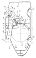
- a container 10 for the collection of water or other liquid picked up by means of a suction head (not shown) in a floor cleaning or drying operation comprises a hollow body in the form of a tank of generally rectangular cross-section and bounded by a bottom wall 11, rear wall 12, top wall 13, front wall 14 and side walls 15.
- An obliquely arranged outlet opening 17 is provided at a comer of the container 10 at the junction of the top and front walls 13,14.
- An outlet chamber 20 is connected to the container 10 at the opening 17.
- the outlet chamber 20 is formed with an air outlet opening 21 which communicates with an air duct 22 leading to the inlet of a motor-driven impeller 23. Opposite the air outlet opening 21 the outlet chamber affords a mouth 24 communicating with the interior of the container 10.
- An air/water separator 30 extends through the outlet chamber 20 to the interior of the container 10.
- the separator 30 comprises an inlet tube 31 having an inlet opening 32 at one end adjacent to the outlet opening 21 and terminating at the other end in an outwardly widening bell 33 which extends at an oblique angle relative to the tube 31 and extends into the container 10 on a centre line 34 arranged at an angle of approximately 45° to the top and front walls 13,14.
- the bell 33 terminates in a rim 35 which extends substantially perpendicular relative to the axis 34 and defines an outlet end 36 having a diameter approximately twice that of the inlet tube 31.
- the side walls of the bell 33 curve smoothly outwardly to merge with the rim 35, and preferably the bell is defined as a surface of revolution swept by a curve at least approximating to part of a hyperbola, parabola or ellipse.
- An annular filter element 40 is arranged at the mouth 24 of the outlet chamber 20 and surrounding the bell 33.
- the filter element 40 comprises an apertured casing 41, which serves to locate the bell 33 within the mouth 24 of the chamber 20, and a porous filter member 42 of relatively large pore-size, typically in the range 1 to 2.5 mm, so as not to impose a significant restriction on the air flow to the outlet 21, whilst affording a large surface area on which any residual entrained droplets of water can coalesce.
- the inlet opening 32 of the tube 31 registers with one end of a suction tube 25 which is connectable at its other end to a suction hose 26 leading to any suitable form of pick-up head (not illustrated).
- Suction is applied to the pick-up head by means of the motor-driven impeller 23 which is located forwardly of the container 10 within a casing 37, and which draws air through the container 10 as indicated by the arrows A/B. Air is thus drawn through the pick-up head, suction hose 26, suction tube 25, inlet tube 31 and bell 33 into the interior of the container 10, around the rim 35 of the bell 33, through the filter member 42 into the outlet chamber 20 to the outlet opening 21 of the air duct 22 and into the impeller 23.
- Liquid which is entrained in the incoming air flow as indicated by arrows A is separated from the air as a result of the reduction in the speed of the air flow which occurs in the bell 33 which widens smoothly in the downstream direction, and the reversal of direction around the rim 35. Any residual droplets which remain entrained in the air flow are caught in the filter member 42 and drain gravitationally towards the bottom of the filter element 40 and the front wall 14 of the container 10, the air flow downstream of the filter member 42, as indicated by arrows B, being substantially free of entrained liquid.
- the outlet chamber 20 may be so dimensioned as to constitute an expansion chamber in which the rate of air flow is further reduced so that any droplets which may pass through the filter element 40 can separate out before the air reaches the outlet opening 21.
- water may be collected in the container 10 until it reaches a level approaching, or even slightly exceeding, the lower edge of the bell 33, without impairment in the efficiency of water separation, the air flow around the lowermost part of the bell 33 causing a local depression in the surface of the collected liquid.
- Ribs 38,39 provided on the top and front walls 13,14 serve as baniers to reduce the risk of collected water splashing into the mouth 24 of the outlet chamber 20 as the appliance is moved.
- rollers 18,19 are provided at the underside of the unit comprising the assembly of casing 37 and container 10 so that the unit may rest on a floor and be pulled over the surface of the floor by means of the hose 26 whilst cleaning is in operation.
- the rear wall 12 of the container 10 is substantially flat and is adapted to serve as an alternative base on which the unit can stand in an upright position, for example on a stair tread. Due to the angled arrangement of the bell 33, air/water separation is performed as efficiently in such alternative orientation, and the appliance can be used in either orientation without requiring any adjustment by the user.
- the container 10 is designed for releasable assembly with the casing 37, so that the contents of the container 10 can be emptied by removing the container from the casing and removing the assembly, of outlet chamber 20 separator 30 and filter 40, whereby the collected liquid can be emptied through the mouth 24.
- a further, interchangeable collection container can be provided for use in place of the collection container 10, such further collection container incorporating a filter or the like for removing dust from the air flow.
- the apparatus may also include a reservoir for a cleaning liquid which is to be applied to the surface to the cleaned by means of a suction head or a separate liquid applicator head.
Landscapes
- Engineering & Computer Science (AREA)
- Mechanical Engineering (AREA)
- Separating Particles In Gases By Inertia (AREA)
- Drying Of Solid Materials (AREA)
- Cleaning By Liquid Or Steam (AREA)
- Filtering Of Dispersed Particles In Gases (AREA)
- Detergent Compositions (AREA)
Description
- This invention relates to liquid pick-up appliances for use in surface cleaning or drying operations wherein liquid is picked-up for example from a floor surface (afforded by a floor or floor covering) or other surface such as afforded by a wall or window by a suction head so as to be entrained in air flow from such head to an air/liquid separator in which entrained liquid is separated from the air flow and collected in a container.
- Such an appliance may be designed and used for drying floor surfaces or picking up spillages, or it may also incorporate a reservoir for a cleaning liquid (which may be water or a suitable cleaning solution) and means for delivering such liquid to a cleaning head, which may be incorporated in, or separate from, the suction head, so that the appliance is capable of carrying out, simultaneously or sequentially, floor cleaning and floor drying operations or similar operations on other surfaces.
- Various types of air/liquid separator have been proposed to enable the liquid to be separated from the air flow and delivered to a collection container. For example British Patent specification 1121225 shows a simple centrifugal separator in which the air flow enters an annular chamber tangentially, the lower side of the chamber being connected to the upper end of a collection container. Our British Patent specification 1601456 shows a separator in which the air flow is radially directed into a radially narrow annular space between the outer wall of a reservoir container and the outer wall of a collection chamber within which the reservoir container is nested, the latter having a central suction duct extending through it, and which at its lower end is formed as a downwardly widening cone with vertical vanes to prevent circular air flow.
- In other examples, labyrinthine separators are employed, as shown in US Patent specification 2986764. In the case of relatively small hand-held devices which in use may be subjected to quite vigorous motion, elaborate arrangements are often employed within the collection container to prevent entrained droplets from being drawn out of the container, as for example in EP 0170720.
- In still other cases a widening inlet tube delivers the air/liquid stream onto baffle arranged across the mouth of the tube, as for example, in German Patent specification 3540956 or US Patent specification 1328339.
- In all such prior arrangements, the air outlet from the collection chamber is located at a position remote from the air/liquid inlet.
- It is an object of the present invention to provide a collection container which can function equally well in different orientations.
- In accordance with the invention we provide a collection container for use with an appliance for picking up liquid by means of a suction head which entrains the liquid in an air flow from said head to said collection container, wherein the collection container comprises an air/liquid separator and a hollow body having two adjacent wall portions which extend substantially perpendicularly to one another, characterised in that said air/liquid separator is arranged with a longitudinal centre line thereof extending from a comer defined by the junction between said adjacent side wall portions and at an oblique angle relative to both of said adjacent side wall portions, and in that said body has two further wall portions which extend substantially perpendicular to one another and meet at a comer opposite that at which said air/liquid separator is disposed, whereby said container can rest in a stable manner on either of said further wall portions respectively in a horizontal orientation on a floor surface being cleaned for movement across such surface or in a vertical orientation for example on one tread of a flight of stairs which are being cleaned.
- Preferably, the air/liquid separator includes an inlet tube extending from an air/liquid inlet and the collection container has an air outlet chamber through which the inlet tube extends, and the end portion of the inlet tube is formed as a bell which widens progressively and smoothly from the inlet tube to an outlet opening having an area at least twice that of the cross-sectional area of the tube. In particular, the tube and outlet opening are conveniently of circular shape in transverse cross-section, and the diameter of the outlet opening is at least approximately twice that of the tube.
- The internal surface of such bell is preferably of outwardly curving form and terminates in a rim portion which extends substantially transversely relative to the axial centre line of the bell. The shape of the bell may be defined as the surface of revolution swept by a curve at least approximating to part of a hyperbola, parabola or ellipse.
- Between the air outlet chamber and the collection container, a filter element may be provided in the space between the inlet tube and the outer walls of the container. The filter element may be formed as a porous member of relatively large pore size (typically in the range 1 to 2.5 mm) so as not to impose a significant restriction on the air flow to the outlet, whilst affording a large surface area on which any residual entrained droplets of water can coalesce and drain towards the interior of the collection container against the outgoing air flow. Suitable material from which such filter may be constructed is a reticulated foam or a filamentary mesh, preferably made of a synthetic plastics material.
- Conveniently, the surface of the filter element facing the collection container is arranged at such an angle relative to the adjacent wall of the container that, in the intended in-use orientation of the container, liquid which percolates back through the filter element can drain gravitationally towards said adjacent wall.
- In a particularly preferred arrangement, the filter element extends obliquely across a comer of the collection container as defined by two adjacent walls thereof, so that the axial centre line of the bell is arranged at a substantially equal angle relative to the two adjacent walls.
- With such an arrangement, the collection container can be disposed in a range of orientations without impairing the efficiency of the separator.
- In particular, this enables the collection container to be housed in, or form part of, a suction cleaner of the canister type which can be used in either horizontal or vertical orientations.
- Thus, the collection container can be associated with an impeller and motor assembly which creates the required air flow in a free-standing unit which, when orientated horizontally, can rest on the floor surface being cleaned and be pulled across such surface and which in the vertical orientation can stand in a stable manner for example on one tread of a flight of stairs which are being cleaned.
- According to a further aspect of the invention an appliance for picking up liquid including a suction head which entrains the liquid in an air flow from said head to an air/liquid separator and a collection container for receiving liquid from said separator, comprising an air/liquid separator according to the first aspect of the invention.
- The invention will now be described by way of example with reference to one embodiment of appliance incorporating a liquid collection container with an air/liquid separator in accordance with the invention, as illustrated in the accompanying drawing.
- In the accompanying drawing a
container 10 for the collection of water or other liquid picked up by means of a suction head (not shown) in a floor cleaning or drying operation comprises a hollow body in the form of a tank of generally rectangular cross-section and bounded by abottom wall 11,rear wall 12,top wall 13,front wall 14 andside walls 15. - An obliquely arranged
outlet opening 17 is provided at a comer of thecontainer 10 at the junction of the top andfront walls - An
outlet chamber 20 is connected to thecontainer 10 at theopening 17. Theoutlet chamber 20 is formed with an air outlet opening 21 which communicates with anair duct 22 leading to the inlet of a motor-drivenimpeller 23. Opposite the air outlet opening 21 the outlet chamber affords amouth 24 communicating with the interior of thecontainer 10. - An air/
water separator 30 extends through theoutlet chamber 20 to the interior of thecontainer 10. - The
separator 30 comprises aninlet tube 31 having an inlet opening 32 at one end adjacent to the outlet opening 21 and terminating at the other end in an outwardly wideningbell 33 which extends at an oblique angle relative to thetube 31 and extends into thecontainer 10 on acentre line 34 arranged at an angle of approximately 45° to the top andfront walls bell 33 terminates in arim 35 which extends substantially perpendicular relative to theaxis 34 and defines an outlet end 36 having a diameter approximately twice that of theinlet tube 31. As can seen, the side walls of thebell 33 curve smoothly outwardly to merge with therim 35, and preferably the bell is defined as a surface of revolution swept by a curve at least approximating to part of a hyperbola, parabola or ellipse. - An
annular filter element 40 is arranged at themouth 24 of theoutlet chamber 20 and surrounding thebell 33. Thefilter element 40 comprises an apertured casing 41, which serves to locate thebell 33 within themouth 24 of thechamber 20, and a porous filter member 42 of relatively large pore-size, typically in the range 1 to 2.5 mm, so as not to impose a significant restriction on the air flow to theoutlet 21, whilst affording a large surface area on which any residual entrained droplets of water can coalesce. - The inlet opening 32 of the
tube 31 registers with one end of asuction tube 25 which is connectable at its other end to asuction hose 26 leading to any suitable form of pick-up head (not illustrated). Suction is applied to the pick-up head by means of the motor-drivenimpeller 23 which is located forwardly of thecontainer 10 within acasing 37, and which draws air through thecontainer 10 as indicated by the arrows A/B. Air is thus drawn through the pick-up head,suction hose 26,suction tube 25,inlet tube 31 andbell 33 into the interior of thecontainer 10, around therim 35 of thebell 33, through the filter member 42 into theoutlet chamber 20 to the outlet opening 21 of theair duct 22 and into theimpeller 23. - Liquid which is entrained in the incoming air flow as indicated by arrows A is separated from the air as a result of the reduction in the speed of the air flow which occurs in the
bell 33 which widens smoothly in the downstream direction, and the reversal of direction around therim 35. Any residual droplets which remain entrained in the air flow are caught in the filter member 42 and drain gravitationally towards the bottom of thefilter element 40 and thefront wall 14 of thecontainer 10, the air flow downstream of the filter member 42, as indicated by arrows B, being substantially free of entrained liquid. - If necessary, the
outlet chamber 20 may be so dimensioned as to constitute an expansion chamber in which the rate of air flow is further reduced so that any droplets which may pass through thefilter element 40 can separate out before the air reaches the outlet opening 21. - In practice, water may be collected in the
container 10 until it reaches a level approaching, or even slightly exceeding, the lower edge of thebell 33, without impairment in the efficiency of water separation, the air flow around the lowermost part of thebell 33 causing a local depression in the surface of the collected liquid. -
Ribs front walls mouth 24 of theoutlet chamber 20 as the appliance is moved. - As illustrated,
rollers casing 37 andcontainer 10 so that the unit may rest on a floor and be pulled over the surface of the floor by means of thehose 26 whilst cleaning is in operation. - However, the
rear wall 12 of thecontainer 10 is substantially flat and is adapted to serve as an alternative base on which the unit can stand in an upright position, for example on a stair tread. Due to the angled arrangement of thebell 33, air/water separation is performed as efficiently in such alternative orientation, and the appliance can be used in either orientation without requiring any adjustment by the user. - The
container 10 is designed for releasable assembly with thecasing 37, so that the contents of thecontainer 10 can be emptied by removing the container from the casing and removing the assembly, ofoutlet chamber 20separator 30 andfilter 40, whereby the collected liquid can be emptied through themouth 24. - If the cleaner is also to be used as an ordinary vacuum cleaner for picking up dust and other dry material, a further, interchangeable collection container can be provided for use in place of the
collection container 10, such further collection container incorporating a filter or the like for removing dust from the air flow. - The apparatus may also include a reservoir for a cleaning liquid which is to be applied to the surface to the cleaned by means of a suction head or a separate liquid applicator head.
- The features disclosed in the foregoing description, or the accompanying drawing, expressed in their specific forms or in terms of a means for performing the disclosed function, or a method or process for attaining the disclosed result, may, separately or in any combination of such features, be utilised for realising the invention in diverse forms thereof.
Claims (11)
- A collection container for use with an appliance for picking up liquid by means of a suction head which entrains the liquid in an air flow from said head to said collection container, wherein the collection container (10) comprises an air/liquid separator (30) and a hollow body (11-15) having two adjacent wall portions (13,14) which extend substantially perpendicularly to one another, characterised in that said air/liquid separator (30) is arranged with a longitudinal centre line (34) thereof extending from a corner defined by the junction between said adjacent side wall portions (13,14) and at an oblique angle relative to both of said adjacent side wall portions (13,14), and in that said body has two further wall portions (11,12) which extend substantially perpendicular to one another and meet at a comer opposite that at which said air/liquid separator (30) is disposed, whereby said container can rest in a stable manner on either of said further wall portions (11,12) respectively in a horizontal orientation on a floor surface being cleaned for movement across such surface or in a vertical orientation for example on one tread of a flight of stairs which are being cleaned.
- A collection container according to Claim 1 wherein said longitudinal centre line (34) is inclined at a substantially equal angle to both of said adjacent wall portions (13,14).
- A collection container according to Claim 1 or Claim 2 wherein the air/liquid separator includes an inlet tube (31) extending from an air/water inlet (32) and the collection container has an air outlet chamber (20) through which said inlet tube (31) extends.
- A collection container according to Claim 3 wherein a filter element (40) is provided in die space between the inlet tube (31) and the walls of the outlet chamber (20).
- A collection container according to Claim 4 wherein the filter element (40) is formed as a porous member (42) of relatively large pore size (typically in the range 1 to 2.5 mm) so as not to impose a significant restriction on the air flow to the outlet, whilst affording a large surface area on which any residual entrained droplets of water can coalesce and drain towards the interior of the collection container against the outgoing air flow.
- A collection container according to Claim 4 wherein the surface of the filter element (40) facing the collection container is arranged at such an angle relative to each of the adjacent walls (13,14) of the container that, in either of the in-use orientations of the container (10), liquid which percolates back through the filter element (40) can drain gravitationally towards a respective one of said adjacent wall (13,14).
- A collection container according to any one of Claims 3 to 6 wherein the inlet tube (31) has an end portion (33) formed as a bell (33) which widens progressively and smoothly to an outlet opening (36) having an area at least twice that of the cross-section area of said inlet tube (31).
- A collection container according to Claim 7 wherein the inlet tube (31) and outlet opening (36) are of circular shape in transverse cross-section, and the diameter of the outlet opening (36) is approximately twice that of said tube (31).
- A collection container according to Claim 8 wherein the internal surface of said bell (33) is of outwardly curving and terminates in a rim portion (35) which extends substantially transversely relative to the axial centre line (34) of the bell (33).
- A collection chamber according to Claim 9 wherein the shape of the bell (33) is defined as the surface of revolution swept by a curve at least approximating to part of a hyperbola, parabola or ellipse.
- An appliance for picking up liquid including a suction head which entrains the liquid in an air flow from said head to an air/liquid separator (30) and a collection container (10) for receiving liquid from said separator, characterised in that it comprises a collection container according to any one of Claims 1 to 10.
Applications Claiming Priority (3)
| Application Number | Priority Date | Filing Date | Title |
|---|---|---|---|
| GB9516689 | 1995-08-15 | ||
| GBGB9516689.8A GB9516689D0 (en) | 1995-08-15 | 1995-08-15 | Liquid pick-upappliances for use insurface cleaning or drying |
| EP96927767A EP0844843B1 (en) | 1995-08-15 | 1996-08-13 | Liquid pick-up appliances for use in surface cleaning or drying |
Related Parent Applications (1)
| Application Number | Title | Priority Date | Filing Date |
|---|---|---|---|
| EP96927767A Division EP0844843B1 (en) | 1995-08-15 | 1996-08-13 | Liquid pick-up appliances for use in surface cleaning or drying |
Publications (3)
| Publication Number | Publication Date |
|---|---|
| EP0933057A2 EP0933057A2 (en) | 1999-08-04 |
| EP0933057A3 EP0933057A3 (en) | 1999-12-08 |
| EP0933057B1 true EP0933057B1 (en) | 2003-03-05 |
Family
ID=10779253
Family Applications (2)
| Application Number | Title | Priority Date | Filing Date |
|---|---|---|---|
| EP99108728A Expired - Lifetime EP0933057B1 (en) | 1995-08-15 | 1996-08-13 | Liquid pick-up appliances for use in surface cleaning or drying |
| EP96927767A Expired - Lifetime EP0844843B1 (en) | 1995-08-15 | 1996-08-13 | Liquid pick-up appliances for use in surface cleaning or drying |
Family Applications After (1)
| Application Number | Title | Priority Date | Filing Date |
|---|---|---|---|
| EP96927767A Expired - Lifetime EP0844843B1 (en) | 1995-08-15 | 1996-08-13 | Liquid pick-up appliances for use in surface cleaning or drying |
Country Status (13)
| Country | Link |
|---|---|
| US (1) | US6055701A (en) |
| EP (2) | EP0933057B1 (en) |
| JP (1) | JP3913272B2 (en) |
| KR (1) | KR19990036437A (en) |
| AU (1) | AU694060B2 (en) |
| BR (1) | BR9610416A (en) |
| CA (1) | CA2229582A1 (en) |
| DE (3) | DE844843T1 (en) |
| ES (2) | ES2121568T3 (en) |
| GB (1) | GB9516689D0 (en) |
| MX (1) | MX9801211A (en) |
| RU (1) | RU2163085C2 (en) |
| WO (1) | WO1997006721A1 (en) |
Families Citing this family (22)
| Publication number | Priority date | Publication date | Assignee | Title |
|---|---|---|---|---|
| US6434783B1 (en) * | 1998-07-09 | 2002-08-20 | Mark Arnold | Vacuum system for pre-wash removal of food/grease materials in dishwasher facilities |
| AT409127B (en) * | 2000-09-18 | 2002-05-27 | Wolfgang Hartl | EXTRACTION SYSTEM FOR POND CLEANING |
| EP1320318B1 (en) | 2000-09-29 | 2012-10-24 | Oreck Holdings, LLC | Contoured intake ducts and fan housing assemblies for floor care machines |
| US7048783B2 (en) * | 2004-04-13 | 2006-05-23 | Oreck Holdings, Llc | Vacuum cleaner air/liquid separator |
| JP2006073256A (en) * | 2004-08-31 | 2006-03-16 | Sanyo Electric Co Ltd | Power supply for vehicle |
| US20070113361A1 (en) * | 2005-11-18 | 2007-05-24 | Chad Reese | Surface cleaning apparatus |
| GB2486666B (en) | 2010-12-22 | 2012-11-07 | Grey Technology Ltd | Vacuum cleaner |
| US8945285B2 (en) * | 2011-12-23 | 2015-02-03 | Valeo Climate Control | Water separator having a gutter |
| US20140237768A1 (en) * | 2013-02-28 | 2014-08-28 | G.B.D. Corp. | Surface cleaning apparatus |
| GB201306512D0 (en) | 2013-04-10 | 2013-05-22 | Grey Technology Ltd | Vacuum cleaner |
| RU2675920C2 (en) | 2013-06-05 | 2018-12-25 | Грей Технолоджи Лимитед | Handheld vacuum cleaner |
| EP4193899B1 (en) | 2013-12-12 | 2024-12-04 | Alfred Kärcher SE & Co. KG | Floor cleaning machine with sweeping lip |
| DE102014114813A1 (en) | 2014-10-13 | 2016-04-14 | Alfred Kärcher Gmbh & Co. Kg | Surface cleaning machine and method for operating a surface cleaning machine |
| DE102014114809A1 (en) | 2014-10-13 | 2016-04-14 | Alfred Kärcher Gmbh & Co. Kg | Surface cleaning machine with moistening device |
| UA118498C2 (en) | 2014-10-13 | 2019-01-25 | Альфред Керхер Гмбх Унд Ко. Кг | Surface-cleaning machine |
| DE102014114776A1 (en) | 2014-10-13 | 2016-04-14 | Alfred Kärcher Gmbh & Co. Kg | Surface cleaning machine |
| WO2017063663A1 (en) | 2015-10-12 | 2017-04-20 | Alfred Kärcher Gmbh & Co. Kg | Surface-cleaning machine |
| GB201603300D0 (en) | 2016-02-25 | 2016-04-13 | Grey Technology Ltd | Suction head for a vacuum cleaner |
| GB201603302D0 (en) | 2016-02-25 | 2016-04-13 | Grey Technology Ltd | Dirt-collection chamber for a vacuum cleaner |
| PL3426122T3 (en) | 2016-03-09 | 2021-12-13 | Alfred Kärcher SE & Co. KG | Surface cleaning machine |
| GB201616598D0 (en) | 2016-09-30 | 2016-11-16 | Grey Technology Limited | Cleaning head for a vacuum cleaner |
| GB201706357D0 (en) | 2017-04-21 | 2017-06-07 | Grey Tech Ltd | Bagged vacuum cleaner |
Family Cites Families (18)
| Publication number | Priority date | Publication date | Assignee | Title |
|---|---|---|---|---|
| US1328339A (en) * | 1918-06-03 | 1920-01-20 | William A Rowe | Floor-cleaning machine |
| US1759947A (en) * | 1924-01-14 | 1930-05-27 | Delco Light Co | Domestic appliance |
| US2093748A (en) * | 1935-05-07 | 1937-09-21 | Bernard C Becker | Suction cleaner |
| BE513878A (en) * | 1951-09-01 | |||
| GB1121225A (en) * | 1966-11-25 | 1968-07-24 | Wladyslaw Brycki | Improvements in or relating to suction cleaning apparatus |
| US3524211A (en) * | 1968-07-05 | 1970-08-18 | Haley Corp | Vacuum cleaner with air director tube |
| AT342548B (en) * | 1974-10-21 | 1978-04-10 | Reflex Moebelpflegemittel | ADDITIONAL UNIT FOR VACUUM CLEANER |
| US4053293A (en) * | 1975-11-28 | 1977-10-11 | Bumstead Woolford Co. | Combination dust collector and heat exchanger |
| US4393538A (en) * | 1979-09-06 | 1983-07-19 | Tennant Company | Scrubber with foam and spray suppressor |
| US4463474A (en) * | 1982-06-07 | 1984-08-07 | Jacobs Paul G | Vacuum cleaner |
| ATE65018T1 (en) * | 1985-09-09 | 1991-07-15 | Cic Int Corp | WET/DRY VACUUM CLEANER. |
| DE3540956A1 (en) * | 1985-11-19 | 1987-05-21 | Duepro Ag | SUCTION UNIT |
| DE3542555A1 (en) * | 1985-12-02 | 1987-06-04 | Bosch Siemens Hausgeraete | SEPARATOR FOR SOLID PARTICLES TAKEN BY A GAS FLOW, IN PART. RIPING AND / OR ICE CRYSTALS |
| US4715872A (en) * | 1986-09-19 | 1987-12-29 | Shopsmith, Inc. | Portable dust collector |
| DE4005891C1 (en) * | 1990-02-24 | 1991-04-25 | Alfred Kaercher Gmbh & Co, 7057 Winnenden, De | |
| US5208940A (en) * | 1990-11-01 | 1993-05-11 | London Charles A | Floor dryer and warning device |
| CA2072710C (en) * | 1991-07-15 | 2002-05-28 | Kent J. Furcron | Improved cleaning device |
| DE4229204C2 (en) * | 1992-09-02 | 1995-10-05 | Henkel Kgaa | Mobile floor cleaning machine |
-
1995
- 1995-08-15 GB GBGB9516689.8A patent/GB9516689D0/en active Pending
-
1996
- 1996-08-13 BR BR9610416A patent/BR9610416A/en not_active Application Discontinuation
- 1996-08-13 DE DE0844843T patent/DE844843T1/en active Pending
- 1996-08-13 EP EP99108728A patent/EP0933057B1/en not_active Expired - Lifetime
- 1996-08-13 EP EP96927767A patent/EP0844843B1/en not_active Expired - Lifetime
- 1996-08-13 KR KR1019980701107A patent/KR19990036437A/en not_active Withdrawn
- 1996-08-13 DE DE69622409T patent/DE69622409T2/en not_active Expired - Fee Related
- 1996-08-13 ES ES96927767T patent/ES2121568T3/en not_active Expired - Lifetime
- 1996-08-13 RU RU98104274/12A patent/RU2163085C2/en not_active IP Right Cessation
- 1996-08-13 CA CA002229582A patent/CA2229582A1/en not_active Abandoned
- 1996-08-13 MX MX9801211A patent/MX9801211A/en unknown
- 1996-08-13 JP JP50904097A patent/JP3913272B2/en not_active Expired - Fee Related
- 1996-08-13 WO PCT/GB1996/001970 patent/WO1997006721A1/en not_active Ceased
- 1996-08-13 ES ES99108728T patent/ES2194400T3/en not_active Expired - Lifetime
- 1996-08-13 DE DE69626551T patent/DE69626551T2/en not_active Expired - Fee Related
- 1996-08-13 US US09/011,655 patent/US6055701A/en not_active Expired - Lifetime
- 1996-08-13 AU AU67471/96A patent/AU694060B2/en not_active Ceased
Also Published As
| Publication number | Publication date |
|---|---|
| KR19990036437A (en) | 1999-05-25 |
| JP2000505660A (en) | 2000-05-16 |
| JP3913272B2 (en) | 2007-05-09 |
| BR9610416A (en) | 1999-07-06 |
| ES2121568T3 (en) | 2003-02-16 |
| ES2194400T3 (en) | 2003-11-16 |
| EP0933057A3 (en) | 1999-12-08 |
| WO1997006721A1 (en) | 1997-02-27 |
| AU6747196A (en) | 1997-03-12 |
| AU694060B2 (en) | 1998-07-09 |
| RU2163085C2 (en) | 2001-02-20 |
| DE69626551T2 (en) | 2003-10-02 |
| CA2229582A1 (en) | 1997-02-27 |
| HK1020664A1 (en) | 2000-05-19 |
| MX9801211A (en) | 1998-04-30 |
| EP0844843A1 (en) | 1998-06-03 |
| DE844843T1 (en) | 1998-10-22 |
| EP0844843B1 (en) | 2002-07-17 |
| US6055701A (en) | 2000-05-02 |
| EP0933057A2 (en) | 1999-08-04 |
| GB9516689D0 (en) | 1995-10-18 |
| DE69622409D1 (en) | 2002-08-22 |
| DE69622409T2 (en) | 2003-09-18 |
| ES2121568T1 (en) | 1998-12-01 |
| DE69626551D1 (en) | 2003-04-10 |
Similar Documents
| Publication | Publication Date | Title |
|---|---|---|
| EP0844843B1 (en) | Liquid pick-up appliances for use in surface cleaning or drying | |
| AU709674B2 (en) | Apparatus for cleaning floors, carpets and the like | |
| MXPA98001211A (en) | Apparatus for collecting liquids that are used for the cleaning or drying of superfic | |
| US6146434A (en) | Cyclonic dirt cup assembly | |
| US5950274A (en) | Separation device for a vacuum cleaner | |
| CN102783928B (en) | Single stage cyclone vacuum cleaner | |
| US8707510B2 (en) | Extraction cleaner and centrifugal air/water separator therefor | |
| JP2721280B2 (en) | Vacuum cleaner | |
| EP0636338A2 (en) | Shroud and cyclonic cleaning apparatus incorporating same | |
| WO1998035602A1 (en) | Device for a cyclone vacuum cleaner | |
| CA2424185A1 (en) | Airflow system for bagless vacuum cleaner | |
| AU2003255215B2 (en) | Handle Tube and Cyclone Vacuum Cleaner Equipped with the Same | |
| GB2322065A (en) | Wet or dry vacuum cleaner | |
| US6494929B2 (en) | Cyclone for suction cleaner | |
| KR20220139900A (en) | wet vacuum cleaner | |
| KR20050019270A (en) | vacuum cleaner for wet and dry cleaning | |
| US20060107487A1 (en) | Water filter vacuum cleaner | |
| KR100206390B1 (en) | Suction kit for vacuum cleaners | |
| HK1020664B (en) | Liquid pick-up appliances for use in surface cleaning or drying | |
| GB2365323A (en) | Vacuum cleaner using water | |
| KR20220139898A (en) | Cyclone unit for wet vacuum cleaners | |
| HK1016049B (en) | Apparatus for cleaning floors, carpets and the like | |
| MXPA98006796A (en) | Apparatus to clean floors, carpets and simi | |
| HK1015239A (en) | Wet or dry vacuum cleaner |
Legal Events
| Date | Code | Title | Description |
|---|---|---|---|
| PUAI | Public reference made under article 153(3) epc to a published international application that has entered the european phase |
Free format text: ORIGINAL CODE: 0009012 |
|
| 17P | Request for examination filed |
Effective date: 19990503 |
|
| AC | Divisional application: reference to earlier application |
Ref document number: 844843 Country of ref document: EP |
|
| AK | Designated contracting states |
Kind code of ref document: A2 Designated state(s): DE ES FR GB IT |
|
| ITCL | It: translation for ep claims filed |
Representative=s name: JACOBACCI & PERANI S.P.A. |
|
| PUAL | Search report despatched |
Free format text: ORIGINAL CODE: 0009013 |
|
| AK | Designated contracting states |
Kind code of ref document: A3 Designated state(s): DE ES FR GB IT |
|
| RIC1 | Information provided on ipc code assigned before grant |
Free format text: 6A 47L 7/00 A, 6A 47L 9/10 B, 6A 47L 11/30 B |
|
| GRAG | Despatch of communication of intention to grant |
Free format text: ORIGINAL CODE: EPIDOS AGRA |
|
| 17Q | First examination report despatched |
Effective date: 20020419 |
|
| GRAG | Despatch of communication of intention to grant |
Free format text: ORIGINAL CODE: EPIDOS AGRA |
|
| GRAH | Despatch of communication of intention to grant a patent |
Free format text: ORIGINAL CODE: EPIDOS IGRA |
|
| GRAH | Despatch of communication of intention to grant a patent |
Free format text: ORIGINAL CODE: EPIDOS IGRA |
|
| GRAA | (expected) grant |
Free format text: ORIGINAL CODE: 0009210 |
|
| DAX | Request for extension of the european patent (deleted) | ||
| AC | Divisional application: reference to earlier application |
Ref document number: 0844843 Country of ref document: EP Kind code of ref document: P |
|
| AK | Designated contracting states |
Designated state(s): DE ES FR GB IT |
|
| REG | Reference to a national code |
Ref country code: GB Ref legal event code: FG4D |
|
| REF | Corresponds to: |
Ref document number: 69626551 Country of ref document: DE Date of ref document: 20030410 Kind code of ref document: P |
|
| ET | Fr: translation filed | ||
| REG | Reference to a national code |
Ref country code: ES Ref legal event code: FG2A Ref document number: 2194400 Country of ref document: ES Kind code of ref document: T3 |
|
| PLBE | No opposition filed within time limit |
Free format text: ORIGINAL CODE: 0009261 |
|
| STAA | Information on the status of an ep patent application or granted ep patent |
Free format text: STATUS: NO OPPOSITION FILED WITHIN TIME LIMIT |
|
| 26N | No opposition filed |
Effective date: 20031208 |
|
| PGFP | Annual fee paid to national office [announced via postgrant information from national office to epo] |
Ref country code: ES Payment date: 20080828 Year of fee payment: 13 |
|
| PGFP | Annual fee paid to national office [announced via postgrant information from national office to epo] |
Ref country code: IT Payment date: 20080825 Year of fee payment: 13 Ref country code: FR Payment date: 20080818 Year of fee payment: 13 |
|
| PGFP | Annual fee paid to national office [announced via postgrant information from national office to epo] |
Ref country code: GB Payment date: 20080822 Year of fee payment: 13 |
|
| PGFP | Annual fee paid to national office [announced via postgrant information from national office to epo] |
Ref country code: DE Payment date: 20081031 Year of fee payment: 13 |
|
| GBPC | Gb: european patent ceased through non-payment of renewal fee |
Effective date: 20090813 |
|
| REG | Reference to a national code |
Ref country code: FR Ref legal event code: ST Effective date: 20100430 |
|
| PG25 | Lapsed in a contracting state [announced via postgrant information from national office to epo] |
Ref country code: FR Free format text: LAPSE BECAUSE OF NON-PAYMENT OF DUE FEES Effective date: 20090831 Ref country code: DE Free format text: LAPSE BECAUSE OF NON-PAYMENT OF DUE FEES Effective date: 20100302 |
|
| REG | Reference to a national code |
Ref country code: ES Ref legal event code: FD2A Effective date: 20090814 |
|
| PG25 | Lapsed in a contracting state [announced via postgrant information from national office to epo] |
Ref country code: GB Free format text: LAPSE BECAUSE OF NON-PAYMENT OF DUE FEES Effective date: 20090813 |
|
| PG25 | Lapsed in a contracting state [announced via postgrant information from national office to epo] |
Ref country code: IT Free format text: LAPSE BECAUSE OF NON-PAYMENT OF DUE FEES Effective date: 20090813 |
|
| PG25 | Lapsed in a contracting state [announced via postgrant information from national office to epo] |
Ref country code: ES Free format text: LAPSE BECAUSE OF NON-PAYMENT OF DUE FEES Effective date: 20090814 |