EP0932720B1 - Continuous pressure decatising of fabrics and setting of staple fibre assemblies - Google Patents
Continuous pressure decatising of fabrics and setting of staple fibre assemblies Download PDFInfo
- Publication number
- EP0932720B1 EP0932720B1 EP97943672A EP97943672A EP0932720B1 EP 0932720 B1 EP0932720 B1 EP 0932720B1 EP 97943672 A EP97943672 A EP 97943672A EP 97943672 A EP97943672 A EP 97943672A EP 0932720 B1 EP0932720 B1 EP 0932720B1
- Authority
- EP
- European Patent Office
- Prior art keywords
- fabric
- drum
- saturated
- treatment zone
- conveying
- Prior art date
- Legal status (The legal status is an assumption and is not a legal conclusion. Google has not performed a legal analysis and makes no representation as to the accuracy of the status listed.)
- Expired - Lifetime
Links
- 239000004744 fabric Substances 0.000 title claims description 140
- 238000000429 assembly Methods 0.000 title description 2
- 230000000712 assembly Effects 0.000 title description 2
- 239000000835 fiber Substances 0.000 title description 2
- 229920006395 saturated elastomer Polymers 0.000 claims description 50
- 238000000034 method Methods 0.000 claims description 29
- 239000000463 material Substances 0.000 claims description 23
- 238000010438 heat treatment Methods 0.000 claims description 18
- 239000004753 textile Substances 0.000 claims description 15
- 238000001035 drying Methods 0.000 claims description 8
- 238000001704 evaporation Methods 0.000 claims description 7
- 238000001816 cooling Methods 0.000 claims description 5
- 230000003019 stabilising effect Effects 0.000 claims description 4
- 238000003825 pressing Methods 0.000 claims description 3
- 238000007789 sealing Methods 0.000 description 11
- 210000002268 wool Anatomy 0.000 description 11
- 229920000742 Cotton Polymers 0.000 description 8
- 241000219146 Gossypium Species 0.000 description 8
- 230000008569 process Effects 0.000 description 6
- 230000006641 stabilisation Effects 0.000 description 5
- 238000010025 steaming Methods 0.000 description 5
- 230000006835 compression Effects 0.000 description 4
- 238000007906 compression Methods 0.000 description 4
- 238000002474 experimental method Methods 0.000 description 4
- XLYOFNOQVPJJNP-UHFFFAOYSA-N water Substances O XLYOFNOQVPJJNP-UHFFFAOYSA-N 0.000 description 4
- 238000007792 addition Methods 0.000 description 3
- 230000008020 evaporation Effects 0.000 description 3
- 230000004048 modification Effects 0.000 description 3
- 238000012986 modification Methods 0.000 description 3
- VQLYBLABXAHUDN-UHFFFAOYSA-N bis(4-fluorophenyl)-methyl-(1,2,4-triazol-1-ylmethyl)silane;methyl n-(1h-benzimidazol-2-yl)carbamate Chemical compound C1=CC=C2NC(NC(=O)OC)=NC2=C1.C=1C=C(F)C=CC=1[Si](C=1C=CC(F)=CC=1)(C)CN1C=NC=N1 VQLYBLABXAHUDN-UHFFFAOYSA-N 0.000 description 2
- 230000008859 change Effects 0.000 description 2
- 238000009833 condensation Methods 0.000 description 2
- 230000005494 condensation Effects 0.000 description 2
- 230000000694 effects Effects 0.000 description 2
- 238000009413 insulation Methods 0.000 description 2
- 239000000203 mixture Substances 0.000 description 2
- 230000035699 permeability Effects 0.000 description 2
- HHPGZDNGIQXYNK-CTHZYMGMSA-N (2r,3r,4s,5s,6r)-2-[(2r,3s,4r,5r,6r)-6-[2-[2-[2-[[(3s,10r,13r,17r)-10,13-dimethyl-17-[(2r)-6-methylheptan-2-yl]-2,3,4,7,8,9,11,12,14,15,16,17-dodecahydro-1h-cyclopenta[a]phenanthren-3-yl]oxy]ethoxy]ethoxy]ethoxy]-4,5-dihydroxy-2-(hydroxymethyl)oxan-3-yl]o Chemical compound O([C@@H]1[C@@H](CO)O[C@H]([C@@H]([C@H]1O)O)OCCOCCOCCO[C@@H]1CC2=CCC3C4CC[C@@H]([C@]4(CCC3[C@@]2(C)CC1)C)[C@H](C)CCCC(C)C)[C@H]1O[C@H](CO)[C@@H](O)[C@H](O)[C@H]1O HHPGZDNGIQXYNK-CTHZYMGMSA-N 0.000 description 1
- 241000139306 Platt Species 0.000 description 1
- 229920000297 Rayon Polymers 0.000 description 1
- 229910000831 Steel Inorganic materials 0.000 description 1
- 244000000188 Vaccinium ovalifolium Species 0.000 description 1
- 230000009471 action Effects 0.000 description 1
- 230000009977 dual effect Effects 0.000 description 1
- 230000003993 interaction Effects 0.000 description 1
- 238000012423 maintenance Methods 0.000 description 1
- 238000004519 manufacturing process Methods 0.000 description 1
- 238000005192 partition Methods 0.000 description 1
- 230000000737 periodic effect Effects 0.000 description 1
- 229920001296 polysiloxane Polymers 0.000 description 1
- 239000002964 rayon Substances 0.000 description 1
- 238000011160 research Methods 0.000 description 1
- 239000007921 spray Substances 0.000 description 1
- 238000005507 spraying Methods 0.000 description 1
- 239000010959 steel Substances 0.000 description 1
- 238000012546 transfer Methods 0.000 description 1
- 238000009834 vaporization Methods 0.000 description 1
- 238000004383 yellowing Methods 0.000 description 1
Images


Classifications
-
- D—TEXTILES; PAPER
- D06—TREATMENT OF TEXTILES OR THE LIKE; LAUNDERING; FLEXIBLE MATERIALS NOT OTHERWISE PROVIDED FOR
- D06B—TREATING TEXTILE MATERIALS USING LIQUIDS, GASES OR VAPOURS
- D06B15/00—Removing liquids, gases or vapours from textile materials in association with treatment of the materials by liquids, gases or vapours
- D06B15/02—Removing liquids, gases or vapours from textile materials in association with treatment of the materials by liquids, gases or vapours by squeezing rollers
-
- D—TEXTILES; PAPER
- D06—TREATMENT OF TEXTILES OR THE LIKE; LAUNDERING; FLEXIBLE MATERIALS NOT OTHERWISE PROVIDED FOR
- D06C—FINISHING, DRESSING, TENTERING OR STRETCHING TEXTILE FABRICS
- D06C7/00—Heating or cooling textile fabrics
-
- D—TEXTILES; PAPER
- D06—TREATMENT OF TEXTILES OR THE LIKE; LAUNDERING; FLEXIBLE MATERIALS NOT OTHERWISE PROVIDED FOR
- D06C—FINISHING, DRESSING, TENTERING OR STRETCHING TEXTILE FABRICS
- D06C15/00—Calendering, pressing, ironing, glossing or glazing textile fabrics
- D06C15/06—Calendering, pressing, ironing, glossing or glazing textile fabrics between rollers and co-operating moving surfaces formed of flexible material, e.g. bands
Definitions
- This invention relates to a method, and apparatus for performing the method, for the continuous pressure decatising of fabrics.
- the invention also extends to a method and apparatus for continuously setting staple fibres, wherein the staple fibres are contained in an assembly of fibres such as a sliver, roving, strand, yam or the like.
- the invention is particularly suitable for setting wool fibre assemblies and decatising woollen and wool containing fabrics (hereinafter the term wool fabric or the like is to be understood as encompassing fabrics containing a mixture of wool and another or other fibres) and will be described hereinafter with reference to such fibres and fabrics, but it is to be understood that the invention is applicable to other staple fibres, and to other fabrics such as, for example, cottons and rayons which are generally decatised to set the material, enhance lustre or impart some dimensional stability.
- Pressure decatising is a finishing treatment whereby a wool fabric's physical and dimensional form is enhanced and then stabilised by the use of heat, moisture, pressure and time.
- a pressure decatising method produces a permanent change in fabric properties by the action of heat and pressurised steam at greater than 100 kPa (1 atm) pressure on a mechanically constrained fabric, and is usually performed during the final stages of fabric production for several reasons:
- One known type of continuous decatising apparatus comprises a perforated heated drum having an endless belt held in tension and wrapped around most of the circumference of the drum.
- the fabric which is conveyed between the surface of the drum and the belt as the drum rotates, is thus pressed between the drum and the belt surface.
- the fabric is also subjected to steam which is introduced through the drum perforations.
- a laminar-shaped enclosure may be formed between an impermeable pressure belt and an unperforated drum. Pressurised steam is generated in this enclosure by vaporisation of moisture carried in by the belt-fabric sandwich.
- the "Super finish-GFP" machine made by Kohlner (now MTECH) provides an example of this latter apparatus.
- the pressure belt in this known type of apparatus simultaneously compresses and seals the fabric against the rotating drum.
- the level of permanent set that can be imparted to the fabric is limited by the tensile strength of the pressure belt because it is the tension in this belt that provides the seal to maintain a saturated atmosphere within the fabric to set the fibres.
- the belts in this apparatus wear quickly and require frequent periodic and thus costly maintenance because of their continuously high tensile stress and high temperature working conditions.
- a further problem with this apparatus arises from the dual role of the pressure belt, that is, it must simultaneously form a high pressure seal with the drum and also apply mechanical pressure to the fabric.
- Another known type of continuous pressure decatising apparatus involves transporting the fabric between two endless belt conveyors through an autoclave containing saturated steam. At least one of the conveyors is permeable and the fabric is subjected to impulsive compression by nip rollers.
- the belt conveyors in this apparatus are tensioned to maintain a desirable fabric finish. Although this tensioning is not as high as in the first described known apparatus, the belts have to be permeable and belt wear is still a problem.
- This apparatus can impart a reasonable permanent finish to wool fabric, however the required treatment time is much longer than that in the first described known apparatus.
- the present invention is based on the realisation that the steaming conditions in a continuous pressure decatising method may be controlled using a surrounding pressurised atmosphere, preferably of air and preferably at ambient temperature, and controlling the pressure of that atmosphere, and that such a surrounding atmosphere could also reduce the belt wear, sealing and insulation problems of the prior art. It was also realised that this principle of using an enclosing compressed gas for controlling steaming conditions could be applied more generally for the setting of staple textile fibres as such.
- a method for continuously pressure decatising a fabric including the steps of
- the invention provides a method for setting staple fibres wherein the fibres are contained in an assembly of fibres such as a sliver, roving, strand, yam or the like, the method including the steps of
- the method of the first and second aspects of the invention may additionally include a step of passing cool gas through the fabric, or the assembly of fibres, to cool it and reduce its regain whilst the fabric is pressed between the two conveying members, or whilst the assembly of fibres is constrained, for stabilising the fabric or the fibres.
- This additional step is preferably also conducted within the region of compressed gas.
- apparatus for continuously pressure decatising a fabric including first and second conveying members for continuously transporting a fabric along a predetermined path, wherein each conveying member includes a facing surface and the fabric is pressed between the facing surfaces as it is transported by the first and second members along the predetermined path, wherein a treatment zone for the fabric is substantively defined by the facing surfaces of the first and second members and a portion of the length of the predetermined path; drive means associated with the first or the second member for moving said first or second member for transporting the fabric; means for providing a saturated or superheated steam atmosphere within the treatment zone; and a pressure vessel for containing a compressed gas; wherein the treatment zone is contained within the pressure vessel and wherein the pressure of the compressed gas is controllable to thereby controllably establish a high temperature for the saturated or superheated steam atmosphere within the treatment zone.
- apparatus for setting staple fibres wherein the fibres are contained in an assembly of fibres such as a sliver, roving, strand, yarn or the like, the apparatus including means for conveying the assembly of fibres through a treatment zone, means for constraining the fibres as they pass through the treatment zone, means for providing a saturated or superheated steam atmosphere at a high temperature within the treatment zone, and a pressure vessel for containing a pressurized gas, wherein the treatment zone is contained within the pressure vessel and wherein the pressure of the compressed gas is controllable to thereby controllably establish a high temperature for the saturated or superheated steam atmosphere within the treatment zone.
- the compressed gas is air at ambient temperature.
- the saturated steam temperature by adjusting the pressure of the surrounding compressed air.
- the temperature of saturated steam at a given pressure is obtainable from Steam Tables at the equivalent vapour pressure.
- the sealing of the treatment zone is not critical because of the surrounding high air pressure. That is, because of the surrounding high air pressure, localized saturated (or superheated) steam is effectively maintained in the treatment zone (the degree of leakage of steam that may occur from the treatment zone is insignificant to the functioning of the decatising process).
- the first and second conveying members may be permeable or impermeable.
- the treatment zone for the fabric is generally the space between the facing surfaces of the two (or the first and second) conveying members over a length of the path of the fabric through the apparatus and there are various options available for providing a saturated or superheated steam atmosphere within this zone. At least one of the conveying members should be heated for the decatising (and thus it will have a heating arrangement associated with it) and this heating may be employed for generating the steam.
- a saturated or superheated steam atmosphere can be established within the treatment zone, simultaneously with the pressing and conveying of a fabric therethrough, by appropriately heating one of the conveying members such that moisture on or in the fabric is rapidly evaporated.
- moisture is applied to the fabric prior to its passage through the treatment zone. This can be done by spraying a surface of the fabric with moisture, which surface should be the one that faces the facing surface or the heated conveying member.
- a moisture laden textile material can be arranged to travel through the treatment zone sandwiched between the fabric being teated and the facing surface of one of the conveying members, which facing surface is suitably heated so as to rapidly evaporate the moisture that is conveyed into the treatment zone by the textile material.
- a permeable belt conveying member may be used in order to release excess moisture from the fabric during treatment.
- a process and apparatus includes introducing steam into the treatment zone through the first conveying member or the second conveying member, or both, which will require that the conveying member(s) concerned be permeable.
- one of the conveying members may be a rotatable drum and steam may be introduced into the treatment zone from inside the drum via suitable perforations through its surface.
- a steam chamber or the like may be provided over a portion of the belt over the drum (effectively the belt/drum interface provides a wall for the chamber).
- pressurized steam is introduced into the treatment zone through the belt.
- the enclosure of such a steam chamber in a pressurized atmosphere such as compressed air helps maintain the saturated steam at a temperature corresponding to this pressure and alleviates the sealing requirements for the chamber relative to the belt, thus reducing a problem which exists with prior art arrangements that employ similar steam chambers.
- the first and second conveying members could be constituted by endless belt conveyors.
- the first conveying member is a heated cylindrical drum, the outer surface of which provides one of said facing surfaces
- the second conveying member is an endless belt that travels around the drum whereby fabric, which is sandwiched between the drum and the belt, can be continuously conveyed through the apparatus via rotation of the drum.
- the drive means associated with the first or second member may be a driving arrangement for rotating the drum.
- the facing surface of the belt is not required to establish a seal with the facing surface of the drum along the longitudinal edges of a fabric. All that is required of the belt is that it be tensionable to exert sufficient lateral pressure to maintain a desired finish on the fabric.
- the drum may be mounted for rotation within a pressure chamber with the belt arranged to enter and exit the chamber through suitable sealing arrangements.
- Compressed air at room temperature can be supplied to the chamber to maintain a suitable pressure therein while the fabric travels through. This arrangement allows for ready variation of the pressure within the chamber.
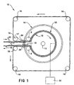
- the apparatus 10 shown in the Figure 1 illustration includes a steel drum 12 which is mounted for rotation, about a shaft 13, within a pressure vessel 14.
- pressure vessel 14 is cylindrical (as illustrated), although it may be any other suitable shape.
- An endless belt 15 is arranged around a series of eight rollers 16 such that it travels into vessel 14 through an entry aperture 17, around about 80% of the circumferential surface of drum 12 and then out an exit aperture 18.
- One of the rollers 16 is adjustable in a known way for adjusting the tension in belt 15, also shaft 13 or one of the rollers 16 is driven.
- a fabric 19 is fed to the apparatus 10 such that it is sandwiched between endless belt 15 and drum 12.
- a textile material 20 for example of cotton which is made wet, can also be fed to apparatus 10 such that it is sandwiched between fabric 19 and the surface of drum 12.
- the entry and exit apertures 17 and 18 for vessel 14 each include a sealing arrangement 24 (which may include rollers) to minimise the leakage of compressed air from vessel 14. Suitable seals are known in the art and are thus not further described herein.
- Drum 12 includes a suitable arrangement (shown substantially by block 22) for heating its surface up to, for example, a temperature of about 180° C. It will be evident from Figure 1 that a clockwise rotation of drum 12 will convey fabric 19 and the wet cotton wrapper 20 through a treatment zone between the heated outer facing surface of drum 12 and the inner facing surface of belt 15, which zone extends around the drum starting from about where the belt 15 contacts the surface of drum 12 after entry into vessel 14 and finishing about where it leaves the drum just prior to its exit from vessel 14.
- a suitable arrangement shown substantially by block 22 for heating its surface up to, for example, a temperature of about 180° C.
- Belt 15 may be made of an impermeable silicone material. As a fabric 19 is transported through the vessel 14, it is compressed between belt 15 and drum 12 sufficiently to ensure the fabric retains its flatness, that is, to ensure that a desirable fabric finish is maintained. This compression is provided by tension in belt 15 assisted by the force which the pressurised atmosphere within vessel 14 exerts on the belt. That is, it is to be understood that belt 15 is tensioned, but this tensioning and the consequential lateral pressure that the belt exerts on the fabric 19 is relatively low in that the belt's tension is required only to exert reasonable lateral pressure to maintain the fabric flatness.
- the interaction between the heated surface of drum 12 and wet surface of wrapper 20 causes a rapid evaporative/condensative heat transfer process to occur which establishes a saturated (or superheated, depending on the temperature and the amount of moisture) steam atmosphere within the treatment zone.
- wrapper 20 which gives a saturated regain to the fabric
- wrapper 20 can be omitted and the surface of the fabric 19 which contacts the heated surface of drum 12 can be moistened prior to entering the apparatus 10.
- free water can be applied to the surface of fabric 19 by a spray (not shown).
- steam may be introduced into the treatment zone via perforations in the drum 12, or from a steam chamber arrangement provided within the pressure vessel 14 via a permeable belt.
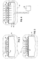
- Figures 2, 3 and 4 are schematic cross-sectional representations (for explaining the operation of the invention) of similar apparatus to that shown in Figure 1, that is, in these views the conveying members movement is in a direction that is normal to the page.
- Figure 2 shows a heated drum 12 around which an endless belt 15 travels with a fabric 19 sandwiched between the outer facing surface of the drum 12 and the inner facing surface of the belt 15.
- Pressure vessel 14 is schematically represented by an enclosing broken line. It contains compressed air at room temperature.
- the Figure 2 embodiment is similar to the Figure 1 embodiment except it does not employ a moisture laden cotton wrapper 20.
- the endless belt 15 of Figure 2 is impermeable and it presses the fabric 19 against the outerfacing surface of heated drum 12.
- steam is generated by the evaporation of moisture in or on the fabric 19.
- the pressurized environment within vessel 14 means that belt 15 need not be a high tensile belt to seal the treatment zone, which zone is defined between the facing surfaces of the belt 15 and drum 12.
- belt 15 seal against the facing surface of drum 12 laterally of the edges of the fabric 19 (see references 26).
- the air pressure within vessel 14 is at 300 kPa (3 atmospheres) (gauge)
- belt 15 only needs to exert an additional pressure of, for example, 50 kPa (0.5 atm) to form a pressurized enclosure for sealing the fabric and set it flat.
- the steam generated in this enclosure is actually subjected to a gauge pressure of 350 kPa (3.5 atm) and therefore the corresponding saturated steam temperature therein is 148°C (from Steam Tables), provided that the temperature of the heated drum 12 is above this temperature.
- a wool fabric 19 provided there is sufficient moisture in the fabric initially, preferably 25% regain or higher, a high level of permanent set can be imparted to the wool fabric in less than 30 secs.
- the fabric 19 can also be wetted prior to entering pressure vessel 14 for improving the level of permanent set imparted, however a drying cycle may be required immediately afterward to stabilize the surface finish.
- belt 15 is permeable and a moisture laden cotton wrapper 20 (as in Figure 1) is sandwiched between the outer facing surface of heated drum 12 and the fabric 19.
- a micro-climate of saturated steam at high temperature, as required to set the wool fibres of fabric 19, can still exist in the treatment zone despite the permeability of belt 15 because of the surrounding region of compressed air in vessel 14. Steam that leaks through the permeable belt 15 will mix with the compressed air and eventually condense on the cold surface of pressure vessel 14 and can be drained away. Because the belt 15 is permeable, there will be an insignificant "cushioning effect" by the saturated steam atmosphere within the treatment zone, thus the belt 15 is only required to exert sufficient mechanical pressure to flat set the fabric 19.
- the evaporation of water held by cotton wrapper 20 is controlled by the drum 12 temperature while the saturated steam temperature can be controlled by controlling the compressed air pressure within vessel 14.
- the saturated steam temperature in the treatment zone will be about 144°C (from Steam Tables) provided that the temperature of the heated drum is set at about 10°C higher to facilitate a high rate of evaporation.
- the amount of steam required is controlled by the wetness of cotton wrapper 20.
- belt 15 is permeable and the cylindrical surface of drum 12 contains perforations 28.
- Saturated steam from a supply 30 is fed to a chamber 32 within drum 12 and forced therefrom through perforations 28, fabric 19 and permeable belt 15.
- the lateral pressure exerted on the fabric 19 can be controlled more exactly than that in the Figure 2 embodiment because of the permeability of belt 15, thus it is expected that these embodiments would give a more consistent treatment.
- the invention also includes the option of preheating belt 15 prior to its wrapping around a fabric 19 on drum 12 to modify the finish on the adjacent surface of fabric 19. It is also within the scope of the invention that the belt 15 tension be varied between batches of fabric to manipulate the setting process and hence modify fabric properties such as handle, smoothness and hygral expansion.
- the apparatus depicted in Figure 1 generally provides for the fabric relaxation/setting stage of a pressure decatising process and that the fabric 19 may then be subjected to a fabric stabilising stage. Suitable fabric stabilisation operations are known in the art. However it is possible to include in the one apparatus both a relaxation/setting and a stabilising stage as in the apparatus depicted by Figures 5 and 6.
- Fig. 5 shows a further embodiment wherein a heated perforated drum 40 is mounted for rotation via shaft 42 within a pressure vessel 44.
- the outer surface of drum 40 may be covered with a permeable textile material 41.
- An endless permeable belt 46 is arranged around a series of rollers 48 such that it travels into vessel 44 through an entry aperture 50, around 80-90% of the circumferential surface of drum 40 and then out an exit aperture 52. Sealing arrangements are provided for the entry and exit apertures as is known.
- a fabric 54 is conveyed through vessel 44 sandwiched between material 41 on drum 40 and endless belt 46.
- a tensioning arrangement 56 for endless belt 46 is located within pressure vessel 44 rather than outside the vessel because this allows better control of the belt tension.
- a steam chamber 58 is arranged over a portion of the circumferential surface of drum 40 within vessel 44 and may include a seal arrangement 60 at the interface between its longitudinal and circumferentially extending walls and the belt 46.
- the belt 46/fabric 54/material 41/drum 40 interface completes the steam chamber.
- the belt 46/fabric 54/material 41/drum 40 interface is permeable such that saturated steam can pass therethrough.
- Steam chamber 58 is arranged relative to drum 40 such that the fabric 54 is subjected to saturated steam soon after it contacts drum 40 and such that the steaming is terminated whilst the fabric still has a distance to travel on the drum which is sufficient for cooling and drying it.
- this apparatus eliminates the need for an additional drying (stabilisation) cycle.
- compressed air at approximately 450 kPa (4.5 atm) gauge is maintained in pressure vessel 44 and a compressed air atmosphere of approximately 400 kPa (4 atm) gauge is maintained within drum 40, with the pressure within steam chamber 58 at approximately 450 kPa (4.5 atm) gauge.
- the seals 60 are not critical because of the surrounding compressed air at 450 kPa. Air needs to be continually pumped into vessel 44 to maintain the pressure therein depending on the flow rate through the belt 46/fabric 54/material 41/drum 40 interface and losses through apertures 50 and 52.
- Fig. 6 shows a modification of the apparatus of Fig. 5 (similar features in the two figures have been accorded the same reference numeral) wherein a cylindrical chamber 62 is provided interiorly of the drum 40. Chamber 62 is fixed, ie. it is stationary and drum 40 rotates around it. The cylindrical wall of drum 40 is closely adjacent the cylindrical wall of chamber 62. Chamber 62 includes internal partitions 64 for providing at least two compartments 66 and 68 therein, and the outer circumferential surface of chamber 62 is perforated.
- a cold shield 70 (in place of steam chamber 58) is provided over the belt 46/fabric 54/material 41/drum 40 interface opposite and in alignment with compartment 66 of chamber 62.
- compressed air at approximately 400 kPa is maintained in vessel 44 whilst compressed air at approximately 450 kPa (gauge) is maintained in compartment 68 and saturated steam at approximately 450 kPa gauge is maintained in compartment 66.
- the fabric 54 undergoes a relaxation/setting stage as it proceeds over compartment 66 and a stabilisation stage (cooling and drying) as it proceeds over compartment 68.
- Cold shield 70 which may be water cooled, is for trapping moisture in the steam through condensation, which condensation can be drained away.
- an apparatus for performing the method may be similar to that disclosed in the applicant's Australian Patent No. 645026 (61669/90), which was published internationally as No. WO 91/02835, with the addition of an enclosing pressure vessel for containing compressed air for controlling the temperature of the steaming treatment.
- this apparatus the fibres in an assembly of fibres are constrained by imparting false twist to the assembly.
- any of the above described embodiments of Figs. 1 to 6 may be used for handling an assembly of fibres in place of a fabric 19.
Landscapes
- Engineering & Computer Science (AREA)
- Textile Engineering (AREA)
- Treatment Of Fiber Materials (AREA)
Description
Claims (24)
- A method for continuously pressure decatising a fabric including the steps ofwherein the high temperature of the saturated or superheated steam is determined substantially by the predetermined pressure of the region of compressed gas.(i) establishing a region of compressed gas having a pre-determined pressure,(ii) continually conveying a fabric through the region of compressed gas by and between two conveying members,(iii) applying saturated or superheated steam at a high temperature to the fabric within the region of compressed gas and simultaneously pressing the fabric between the two conveying members,
- A method as claimed in claim 1 including heating one of said two members such that moisture contained in or on the fabric is evaporated to thereby provide the saturated or superheated steam.
- A method as claimed in claim 1 including continuously conveying a moisture laden textile material through the region of compressed gas by and between said two conveying members such that the moisture laden textile material is in facing contact with the fabric, and heating the one of said two conveying members that is adjacent the moisture laden textile material such that the moisture contained in or on that textile material is evaporated to thereby provide the saturated or superheated steam.
- A method as claimed in claim 1 wherein the two conveying members are permeable and the saturated or superheated steam is passed through the two conveying members for application to the fabric from a pressurized supply of the steam.
- A method as claimed in claim 1 including an additional step of passing gas through the fabric to cool the fabric and reduce its regain while the fabric is pressed between the two conveying members for stabilising the fabric.
- A method as claimed in claim 5 wherein the additional step is conducted within the region of compressed gas.
- A method as claimed in any one of claims 1 to 6 wherein the predetermined pressure of the region of compressed gas is varied to thereby vary the high temperature of the saturated or superheated steam.
- A method as claimed in any one of claims 1 to 6 wherein the compressed gas is air at ambient temperature.
- A method for setting staple fibres wherein the fibres are contained in an assembly of fibres such as a sliver, roving, strand, yarn or the like, the method including the steps ofwherein the high temperature of the saturated or superheated steam is determined substantially by the predetermined pressure of the region of compressed gas.(i) establishing a region of compressed gas having a predetermined pressure,(ii) continually conveying the assembly of fibres through the region of compressed gas,(iii) applying saturated or superheated steam at a high temperature to the assembly of fibres within the region of compressed gas and simultaneously constraining the fibres in the assembly of fibres,
- Apparatus for continuously pressure decatising a fabric including first and second conveying members for continuously transporting a fabric along a predetermined path, wherein each conveying member includes a facing surface and the fabric is pressed between the facing surfaces as it is transported by the first and second conveying members along the predetermined path, wherein a treatment zone for the fabric is substantively defined by the facing surfaces of the first and second conveying members and a portion of the length of the predetermined path; drive means associated with the first or the second conveying member for moving said first or second conveying member for transporting the fabric; means for providing a saturated or superheated steam atmosphere within the treatment zone; and a pressure vessel for containing a compressed gas, wherein the treatment zone is contained within the pressure vessel and wherein the pressure of the compressed gas is controllable to thereby controllably establish a high temperature for the saturated or superheated steam atmosphere within the treatment zone.
- Apparatus as claimed in claim 10 wherein the means for providing a saturated or superheated steam atmosphere within the treatment zone includes a heating arrangement associated with the first or the second conveying member, wherein the heating arrangement heats its associated first or second conveying member for evaporating moisture contained in or on the fabric when the fabric contacts said heated conveying member.
- Apparatus as claimed in claim 11 wherein the first and second conveying members are impermeable.
- Apparatus as claimed in claim 10 wherein the means for providing a saturated or superheated steam atmosphere within the treatment zone includes a heating arrangement associated with the first or the second conveying member and a moisture laden textile material, wherein the moisture laden textile material is arranged to be transported through the treatment zone together with the fabric to be decatised between the facing surfaces of the first and second conveying members with the moisture laden textile material lying adjacent the facing surface of the conveying member with which the heating arrangement is associated, wherein the heating arrangement heats its associated first or second conveying member for evaporating moisture contained in or on the moisture laden textile material when that material contacts said heated conveying member.
- Apparatus as claimed in claim 13 wherein said first or second conveying member which is not associated with the heating arrangement is permeable.
- Apparatus as claimed in claim 10 including a heating arrangement associated with the first or the second conveying member, wherein the first and the second conveying members are permeable and wherein the means for providing a saturated or superheated steam atmosphere within the treatment zone includes a chamber for providing a pressurized supply of steam, wherein the chamber is arranged for steam to pass therefrom through the first and the second conveying members and thus through a fabric therebetween.
- Apparatus as claimed in claim 10 wherein the first conveying member is a drum which is mounted for rotation within the pressure vessel, and wherein the second conveying member is an endless belt which enters the pressure vessel at an entry aperture, travels around the drum and then exits the pressure vessel at an exit aperture adjacent its entry aperture, wherein seals are provided at the entry and exit apertures in the pressure vessel for maintaining the pressure of a compressed gas therein, wherein a fabric is continuously transportable through the pressure vessel when sandwiched between the endless belt and surface of the drum, wherein the means for providing a saturated or superheated steam atmosphere within the treatment zone includes a heating arrangement associated with the drum for heating its facing surface.
- Apparatus as claimed in claim 16 wherein the drum and the endless belt are impermeable, and wherein the heating arrangement associated with the drum for heating its facing surface is for evaporating moisture contained in or on the fabric when the fabric contacts said heated drum surface.
- Apparatus as claimed in claim 16 wherein the drum is impermeable and the endless belt is permeable, wherein the means for providing a saturated or superheated steam atmosphere additionally includes a moisture laden textile material which is transportable through the treatment zone, together with the fabric to be decatised, between the facing surfaces of the drum and the fabric, wherein the heating arrangement heats the facing surface of the drum for evaporating the moisture contained in or on the moisture laden textile material when that material contacts said heated facing surface.
- Apparatus as claimed in claim 16 wherein the drum and the endless belt are permeable and the means for providing a saturated or superheated steam atmosphere within the treatment zone includes a chamber for providing a pressurized supply of steam, wherein the chamber is arranged for steam to pass therefrom through both the drum and the endless belt with the fabric therebetween.
- Apparatus as claimed in claim 19 wherein the chamber is located inside the drum such that the pressurized steam enters the treatment zone through the drum.
- Apparatus as claimed in claim 19 wherein the chamber is located over the endless belt such that the pressurized steam enters the treatment zone through the endless belt.
- Apparatus as claimed in claim 20 wherein a further chamber is located inside the drum for passing pressurized gas at ambient temperature through the fabric after it passes the first defined (steam) chamber for cooling and drying the fabric within the pressure vessel.
- Apparatus as claimed in claim 21 wherein the chamber extends around a portion of the circumferential surface of the drum such that a further portion thereof is available for gas from the pressure vessel to pass through the fabric for cooling and drying the fabric within the pressure vessel.
- Apparatus for setting staple fibres wherein the fibres are contained in an assembly of fibres such as a sliver, roving, strand, yam or the like, the apparatus including means for conveying the assembly, of fibres through a treatment zone, means for constraining the fibres as they pass through the treatment zone, means for providing a saturated or superheated steam atmosphere at a high temperature within the treatment zone, and a pressure vessel for containing a pressurized gas, wherein the treatment zone is contained within the pressure vessel and wherein the pressure of the compressed gas is controllable to thereby controllably establish a high temperature for the saturated or superheated steam atmosphere within the treatment zone.
Applications Claiming Priority (3)
| Application Number | Priority Date | Filing Date | Title |
|---|---|---|---|
| AUPO304296 | 1996-10-17 | ||
| AUPO3042A AUPO304296A0 (en) | 1996-10-17 | 1996-10-17 | Continuous decatising process and apparatus |
| PCT/AU1997/000691 WO1998017853A1 (en) | 1996-10-17 | 1997-10-16 | Continuous pressure decatising of fabrics and setting of staple fibre assemblies |
Publications (3)
| Publication Number | Publication Date |
|---|---|
| EP0932720A1 EP0932720A1 (en) | 1999-08-04 |
| EP0932720A4 EP0932720A4 (en) | 2000-07-12 |
| EP0932720B1 true EP0932720B1 (en) | 2003-06-18 |
Family
ID=3797351
Family Applications (1)
| Application Number | Title | Priority Date | Filing Date |
|---|---|---|---|
| EP97943672A Expired - Lifetime EP0932720B1 (en) | 1996-10-17 | 1997-10-16 | Continuous pressure decatising of fabrics and setting of staple fibre assemblies |
Country Status (8)
| Country | Link |
|---|---|
| US (1) | US6381883B1 (en) |
| EP (1) | EP0932720B1 (en) |
| JP (1) | JP3927244B2 (en) |
| KR (1) | KR100450032B1 (en) |
| AU (1) | AUPO304296A0 (en) |
| DE (1) | DE69722948T2 (en) |
| ES (1) | ES2201322T3 (en) |
| WO (1) | WO1998017853A1 (en) |
Families Citing this family (13)
| Publication number | Priority date | Publication date | Assignee | Title |
|---|---|---|---|---|
| KR100362539B1 (en) * | 2000-10-26 | 2002-12-05 | 홍성규 | Heat exchanger installation steam blowing |
| EP1428923B1 (en) * | 2002-12-09 | 2008-05-07 | Sperotto Rimar S.R.L. | Apparatus for humidifying continuous textile materials and associated method |
| US20040238106A1 (en) * | 2003-05-27 | 2004-12-02 | Velleman Stephan G. | Prepreg forming apparatus |
| ITUD20060026A1 (en) * | 2006-02-02 | 2007-08-03 | Roberto Franchetti | PROCEDURE AND DEVICE FOR FINISHING A FABRIC |
| ITMI20061919A1 (en) * | 2006-10-06 | 2008-04-07 | Biella Shrunk Process S A S | EQUIPMENT FOR CONTINUOUS AUTOCLAVE DECATITATION |
| ITMI20081362A1 (en) * | 2008-07-24 | 2010-01-25 | Biella Shrunk Process S A S Di Pie Tro Alberto & | CONTINUOUS CYCLE FINISHING SYSTEM FOR FABRICS |
| US20100291308A1 (en) * | 2009-05-14 | 2010-11-18 | Veeco Instruments Inc. | Web Substrate Deposition System |
| ITUD20130150A1 (en) * | 2013-11-14 | 2015-05-15 | Roberto Franchetti | PROCESS OF TREATMENT OF TEXTILE MATERIAL AND ITS RELATED TREATMENT APPARATUS |
| KR102336273B1 (en) | 2018-06-15 | 2021-12-06 | 한화솔루션 주식회사 | Isomerization method of cyclohexane dicarboxylic acid |
| ES2947448T3 (en) * | 2018-09-13 | 2023-08-09 | Salvade Srl | Machine for the continuous treatment of fabrics, namely, for the control of dimensional stability |
| CN111764083A (en) * | 2020-06-27 | 2020-10-13 | 连云港如年实业有限公司 | A mixed steam setting machine |
| IT202200010151A1 (en) * | 2022-05-17 | 2023-11-17 | Red Carpet S R L | A MACHINE FOR CONTINUOUS DECATISING |
| CN115682681B (en) * | 2022-11-04 | 2024-06-25 | 铜陵华源金昌印染有限责任公司 | Automatic printing and dyeing drying equipment for printing and dyeing fabrics and drying method thereof |
Family Cites Families (9)
| Publication number | Priority date | Publication date | Assignee | Title |
|---|---|---|---|---|
| DE1926742C3 (en) * | 1969-05-24 | 1979-08-02 | Vepa Ag, Riehen B. Basel (Schweiz) | Device for the continuous treatment of textile goods or the like |
| US4197663A (en) * | 1978-09-21 | 1980-04-15 | Firma Drabert Sohne | Apparatus for continuous pressing and steaming of fabric |
| DE3316127C2 (en) | 1983-05-03 | 1986-07-31 | Maschinenfabrik L. Ph. Hemmer GmbH & Co KG, 5100 Aachen | Methods of decating, in particular continuous decating |
| DE3412982C2 (en) | 1984-04-06 | 1986-04-17 | Johannes Menschner Maschinenfabrik Gmbh & Co Kg, 4060 Viersen | Method and device for the continuous dehumidification, drying, stabilization and other thermal treatments of web-shaped goods, e.g. woven or knitted fabrics made of wool, wool blends, cotton, cotton blends, nonwovens and the like. |
| US4625433A (en) * | 1985-04-18 | 1986-12-02 | Owens-Corning Fiberglas Corporation | Fibrous pack drying method and apparatus |
| IT1202577B (en) | 1987-02-20 | 1989-02-09 | Pietro Alberto | EQUIPMENT FOR THE CONTINUOUS DECATIZATION OF FABRICS IN AUTOCLAVE |
| DE69030668T2 (en) * | 1989-08-17 | 1997-11-27 | Commonwealth Scientific And Industrial Research Organisation, Campbell | STRETCH OF STACKED FIBERS |
| US5123134A (en) * | 1990-03-15 | 1992-06-23 | Pietro Alberto | Method for supplying steam to an autoclave for decatizing |
| US5590549A (en) | 1992-11-02 | 1997-01-07 | Alberto; Pietro | Device for feeding into and withdrawing fabrics from an autoclave for continuous decatizing |
-
1996
- 1996-10-17 AU AUPO3042A patent/AUPO304296A0/en not_active Abandoned
-
1997
- 1997-10-16 US US09/284,912 patent/US6381883B1/en not_active Expired - Fee Related
- 1997-10-16 WO PCT/AU1997/000691 patent/WO1998017853A1/en not_active Ceased
- 1997-10-16 ES ES97943672T patent/ES2201322T3/en not_active Expired - Lifetime
- 1997-10-16 KR KR10-1999-7003312A patent/KR100450032B1/en not_active Expired - Fee Related
- 1997-10-16 DE DE69722948T patent/DE69722948T2/en not_active Expired - Fee Related
- 1997-10-16 JP JP51872398A patent/JP3927244B2/en not_active Expired - Fee Related
- 1997-10-16 EP EP97943672A patent/EP0932720B1/en not_active Expired - Lifetime
Also Published As
| Publication number | Publication date |
|---|---|
| KR20000049213A (en) | 2000-07-25 |
| WO1998017853A1 (en) | 1998-04-30 |
| EP0932720A1 (en) | 1999-08-04 |
| DE69722948T2 (en) | 2004-05-19 |
| ES2201322T3 (en) | 2004-03-16 |
| JP3927244B2 (en) | 2007-06-06 |
| JP2001502386A (en) | 2001-02-20 |
| DE69722948D1 (en) | 2003-07-24 |
| AUPO304296A0 (en) | 1996-11-14 |
| EP0932720A4 (en) | 2000-07-12 |
| KR100450032B1 (en) | 2004-09-22 |
| US6381883B1 (en) | 2002-05-07 |
Similar Documents
| Publication | Publication Date | Title |
|---|---|---|
| US6381883B1 (en) | Continuous pressure decatising of fabrics and setting of staple fibre assemblies | |
| JPH04272266A (en) | Method and device for continuous humidification of strip-like textile goods | |
| US3594914A (en) | Process and apparatus for continuously relaxing textile fabrics | |
| JPH10506962A (en) | Fiber woven fabric drying and smoothing equipment | |
| AU715005B2 (en) | Continuous pressure decatising of fabrics and setting of staple fibre assemblies | |
| EP1608807B1 (en) | Method and machine for treating textile materials by ammonia or other liquids | |
| JPH02145850A (en) | Producing device for shrinkage of cloth | |
| JPH05195416A (en) | Continuous cloth decatizing device and related method | |
| JPS63312000A (en) | Process and related apparatus for continuously decatizing fabric | |
| US3478401A (en) | Method and apparatus for treating textile yarn | |
| EP1055764B1 (en) | Method and device for finishing knitted or woven fabrics | |
| EP0950748B1 (en) | Compaction device for fabrics | |
| US2571494A (en) | Apparatus for the treatment of textiles | |
| US3932905A (en) | Method of dyeing a textile web | |
| US2584753A (en) | Method for treatment of textiles | |
| CN101522977B (en) | Apparatus for continuous decatizing in autoclave | |
| US3908410A (en) | Apparatus for the treatment of textile fibers and fabrics | |
| US4756036A (en) | Continuous treatment of strip textile fabrics | |
| JPH0718084B2 (en) | Method for continuously evaporating and setting strip-shaped fiber products | |
| US3277552A (en) | Method and apparatus for the compressive shrinking of textile fabrics | |
| GB2058862A (en) | Steam-felting Woollen Cloth | |
| JPH07145551A (en) | Device for continuously pressing, steaming and setting strip-shaped fiber products | |
| US3520069A (en) | Process and apparatus for wash-and-wear finishing of woven cloths,knitted goods or fiber fleeces of cellulose fibers | |
| GB2051157A (en) | Weight-reducing and Felting of a Cloth | |
| WO1991012363A1 (en) | Treating fabric to retard flammability |
Legal Events
| Date | Code | Title | Description |
|---|---|---|---|
| PUAI | Public reference made under article 153(3) epc to a published international application that has entered the european phase |
Free format text: ORIGINAL CODE: 0009012 |
|
| 17P | Request for examination filed |
Effective date: 19990421 |
|
| AK | Designated contracting states |
Kind code of ref document: A1 Designated state(s): CH DE ES FR GB IT LI |
|
| A4 | Supplementary search report drawn up and despatched |
Effective date: 20000531 |
|
| AK | Designated contracting states |
Kind code of ref document: A4 Designated state(s): CH DE ES FR GB IT LI |
|
| GRAH | Despatch of communication of intention to grant a patent |
Free format text: ORIGINAL CODE: EPIDOS IGRA |
|
| GRAH | Despatch of communication of intention to grant a patent |
Free format text: ORIGINAL CODE: EPIDOS IGRA |
|
| GRAA | (expected) grant |
Free format text: ORIGINAL CODE: 0009210 |
|
| AK | Designated contracting states |
Designated state(s): CH DE ES FR GB IT LI |
|
| REG | Reference to a national code |
Ref country code: GB Ref legal event code: FG4D |
|
| REG | Reference to a national code |
Ref country code: CH Ref legal event code: EP |
|
| REF | Corresponds to: |
Ref document number: 69722948 Country of ref document: DE Date of ref document: 20030724 Kind code of ref document: P |
|
| REG | Reference to a national code |
Ref country code: CH Ref legal event code: NV Representative=s name: DR. LUSUARDI AG |
|
| REG | Reference to a national code |
Ref country code: ES Ref legal event code: FG2A Ref document number: 2201322 Country of ref document: ES Kind code of ref document: T3 |
|
| ET | Fr: translation filed | ||
| PLBE | No opposition filed within time limit |
Free format text: ORIGINAL CODE: 0009261 |
|
| STAA | Information on the status of an ep patent application or granted ep patent |
Free format text: STATUS: NO OPPOSITION FILED WITHIN TIME LIMIT |
|
| 26N | No opposition filed |
Effective date: 20040319 |
|
| PGFP | Annual fee paid to national office [announced via postgrant information from national office to epo] |
Ref country code: GB Payment date: 20061011 Year of fee payment: 10 |
|
| PGFP | Annual fee paid to national office [announced via postgrant information from national office to epo] |
Ref country code: DE Payment date: 20061012 Year of fee payment: 10 |
|
| PGFP | Annual fee paid to national office [announced via postgrant information from national office to epo] |
Ref country code: CH Payment date: 20061013 Year of fee payment: 10 |
|
| PGFP | Annual fee paid to national office [announced via postgrant information from national office to epo] |
Ref country code: IT Payment date: 20061031 Year of fee payment: 10 |
|
| PGFP | Annual fee paid to national office [announced via postgrant information from national office to epo] |
Ref country code: ES Payment date: 20061124 Year of fee payment: 10 |
|
| REG | Reference to a national code |
Ref country code: CH Ref legal event code: PFA Owner name: COMMONWEALTH SCIENTIFIC AND INDUSTRIAL RESEARCH O Free format text: COMMONWEALTH SCIENTIFIC AND INDUSTRIAL RESEARCH ORGANISATION#LIMESTONE AVENUE#CAMPBELL, AUSTRALIAN CAPITAL TERRITORY 2612 (AU) -TRANSFER TO- COMMONWEALTH SCIENTIFIC AND INDUSTRIAL RESEARCH ORGANISATION#LIMESTONE AVENUE#CAMPBELL, AUSTRALIAN CAPITAL TERRITORY 2612 (AU) |
|
| GBPC | Gb: european patent ceased through non-payment of renewal fee |
Effective date: 20071016 |
|
| REG | Reference to a national code |
Ref country code: CH Ref legal event code: PL |
|
| PG25 | Lapsed in a contracting state [announced via postgrant information from national office to epo] |
Ref country code: LI Free format text: LAPSE BECAUSE OF NON-PAYMENT OF DUE FEES Effective date: 20071031 Ref country code: DE Free format text: LAPSE BECAUSE OF NON-PAYMENT OF DUE FEES Effective date: 20080501 Ref country code: CH Free format text: LAPSE BECAUSE OF NON-PAYMENT OF DUE FEES Effective date: 20071031 |
|
| REG | Reference to a national code |
Ref country code: FR Ref legal event code: ST Effective date: 20080630 |
|
| PGFP | Annual fee paid to national office [announced via postgrant information from national office to epo] |
Ref country code: FR Payment date: 20061010 Year of fee payment: 10 |
|
| PG25 | Lapsed in a contracting state [announced via postgrant information from national office to epo] |
Ref country code: GB Free format text: LAPSE BECAUSE OF NON-PAYMENT OF DUE FEES Effective date: 20071016 |
|
| REG | Reference to a national code |
Ref country code: ES Ref legal event code: FD2A Effective date: 20071017 |
|
| PG25 | Lapsed in a contracting state [announced via postgrant information from national office to epo] |
Ref country code: FR Free format text: LAPSE BECAUSE OF NON-PAYMENT OF DUE FEES Effective date: 20071031 Ref country code: ES Free format text: LAPSE BECAUSE OF NON-PAYMENT OF DUE FEES Effective date: 20071017 |
|
| PG25 | Lapsed in a contracting state [announced via postgrant information from national office to epo] |
Ref country code: IT Free format text: LAPSE BECAUSE OF NON-PAYMENT OF DUE FEES Effective date: 20071016 |