EP0932627B1 - Method for improved cooling of fluidized bed polymer reactor - Google Patents
Method for improved cooling of fluidized bed polymer reactor Download PDFInfo
- Publication number
- EP0932627B1 EP0932627B1 EP97912853A EP97912853A EP0932627B1 EP 0932627 B1 EP0932627 B1 EP 0932627B1 EP 97912853 A EP97912853 A EP 97912853A EP 97912853 A EP97912853 A EP 97912853A EP 0932627 B1 EP0932627 B1 EP 0932627B1
- Authority
- EP
- European Patent Office
- Prior art keywords
- gas
- reactor
- liquid
- cooling
- fluidized bed
- Prior art date
- Legal status (The legal status is an assumption and is not a legal conclusion. Google has not performed a legal analysis and makes no representation as to the accuracy of the status listed.)
- Expired - Lifetime
Links
- 238000000034 method Methods 0.000 title claims abstract description 54
- 238000001816 cooling Methods 0.000 title claims abstract description 44
- 229920000642 polymer Polymers 0.000 title description 12
- 239000007788 liquid Substances 0.000 claims abstract description 65
- 239000012530 fluid Substances 0.000 claims abstract description 47
- 239000007789 gas Substances 0.000 claims description 58
- 239000000178 monomer Substances 0.000 claims description 20
- 238000005243 fluidization Methods 0.000 claims description 11
- 239000003054 catalyst Substances 0.000 claims description 9
- 238000006243 chemical reaction Methods 0.000 claims description 9
- 239000000203 mixture Substances 0.000 claims description 8
- 239000007787 solid Substances 0.000 claims description 7
- 239000004711 α-olefin Substances 0.000 claims description 5
- 150000001336 alkenes Chemical class 0.000 claims description 4
- 238000001311 chemical methods and process Methods 0.000 claims description 3
- 150000001925 cycloalkenes Chemical class 0.000 claims description 3
- 238000011112 process operation Methods 0.000 claims description 3
- 239000000376 reactant Substances 0.000 claims description 3
- 125000000391 vinyl group Chemical group [H]C([*])=C([H])[H] 0.000 claims description 3
- 229920002554 vinyl polymer Polymers 0.000 claims description 3
- 239000000112 cooling gas Substances 0.000 claims description 2
- -1 ethylene, propylene Chemical group 0.000 claims description 2
- 238000010926 purge Methods 0.000 claims description 2
- 239000000463 material Substances 0.000 claims 1
- 238000006116 polymerization reaction Methods 0.000 abstract description 4
- 238000007906 compression Methods 0.000 description 14
- 230000006835 compression Effects 0.000 description 13
- 230000008901 benefit Effects 0.000 description 7
- 150000001875 compounds Chemical class 0.000 description 7
- 238000004519 manufacturing process Methods 0.000 description 6
- 239000002826 coolant Substances 0.000 description 5
- 238000005516 engineering process Methods 0.000 description 3
- 238000009834 vaporization Methods 0.000 description 3
- 230000008016 vaporization Effects 0.000 description 3
- LIKMAJRDDDTEIG-UHFFFAOYSA-N 1-hexene Chemical compound CCCCC=C LIKMAJRDDDTEIG-UHFFFAOYSA-N 0.000 description 2
- IJGRMHOSHXDMSA-UHFFFAOYSA-N Atomic nitrogen Chemical compound N#N IJGRMHOSHXDMSA-UHFFFAOYSA-N 0.000 description 2
- VGGSQFUCUMXWEO-UHFFFAOYSA-N Ethene Chemical compound C=C VGGSQFUCUMXWEO-UHFFFAOYSA-N 0.000 description 2
- 239000005977 Ethylene Substances 0.000 description 2
- 230000009286 beneficial effect Effects 0.000 description 2
- 238000009833 condensation Methods 0.000 description 2
- 230000005494 condensation Effects 0.000 description 2
- 229920001577 copolymer Polymers 0.000 description 2
- 229930195733 hydrocarbon Natural products 0.000 description 2
- 150000002430 hydrocarbons Chemical class 0.000 description 2
- 238000002347 injection Methods 0.000 description 2
- 239000007924 injection Substances 0.000 description 2
- VNWKTOKETHGBQD-UHFFFAOYSA-N methane Chemical compound C VNWKTOKETHGBQD-UHFFFAOYSA-N 0.000 description 2
- 238000005086 pumping Methods 0.000 description 2
- 230000003134 recirculating effect Effects 0.000 description 2
- 239000004215 Carbon black (E152) Substances 0.000 description 1
- 229920000089 Cyclic olefin copolymer Polymers 0.000 description 1
- OTMSDBZUPAUEDD-UHFFFAOYSA-N Ethane Chemical compound CC OTMSDBZUPAUEDD-UHFFFAOYSA-N 0.000 description 1
- 238000009825 accumulation Methods 0.000 description 1
- 239000000498 cooling water Substances 0.000 description 1
- 238000010586 diagram Methods 0.000 description 1
- 230000000694 effects Effects 0.000 description 1
- 239000001257 hydrogen Substances 0.000 description 1
- 229910052739 hydrogen Inorganic materials 0.000 description 1
- 125000004435 hydrogen atom Chemical class [H]* 0.000 description 1
- 239000012535 impurity Substances 0.000 description 1
- 230000006698 induction Effects 0.000 description 1
- 238000003780 insertion Methods 0.000 description 1
- 229910052757 nitrogen Inorganic materials 0.000 description 1
- 229920000098 polyolefin Polymers 0.000 description 1
- 239000000843 powder Substances 0.000 description 1
- 229920006395 saturated elastomer Polymers 0.000 description 1
- 229930195734 saturated hydrocarbon Natural products 0.000 description 1
- 238000000926 separation method Methods 0.000 description 1
- 238000007086 side reaction Methods 0.000 description 1
- 239000000126 substance Substances 0.000 description 1
- 230000005514 two-phase flow Effects 0.000 description 1
- 238000011144 upstream manufacturing Methods 0.000 description 1
Images

Classifications
-
- B—PERFORMING OPERATIONS; TRANSPORTING
- B01—PHYSICAL OR CHEMICAL PROCESSES OR APPARATUS IN GENERAL
- B01J—CHEMICAL OR PHYSICAL PROCESSES, e.g. CATALYSIS OR COLLOID CHEMISTRY; THEIR RELEVANT APPARATUS
- B01J8/00—Chemical or physical processes in general, conducted in the presence of fluids and solid particles; Apparatus for such processes
- B01J8/18—Chemical or physical processes in general, conducted in the presence of fluids and solid particles; Apparatus for such processes with fluidised particles
- B01J8/24—Chemical or physical processes in general, conducted in the presence of fluids and solid particles; Apparatus for such processes with fluidised particles according to "fluidised-bed" technique
-
- B—PERFORMING OPERATIONS; TRANSPORTING
- B01—PHYSICAL OR CHEMICAL PROCESSES OR APPARATUS IN GENERAL
- B01J—CHEMICAL OR PHYSICAL PROCESSES, e.g. CATALYSIS OR COLLOID CHEMISTRY; THEIR RELEVANT APPARATUS
- B01J8/00—Chemical or physical processes in general, conducted in the presence of fluids and solid particles; Apparatus for such processes
- B01J8/18—Chemical or physical processes in general, conducted in the presence of fluids and solid particles; Apparatus for such processes with fluidised particles
- B01J8/1836—Heating and cooling the reactor
-
- C—CHEMISTRY; METALLURGY
- C08—ORGANIC MACROMOLECULAR COMPOUNDS; THEIR PREPARATION OR CHEMICAL WORKING-UP; COMPOSITIONS BASED THEREON
- C08F—MACROMOLECULAR COMPOUNDS OBTAINED BY REACTIONS ONLY INVOLVING CARBON-TO-CARBON UNSATURATED BONDS
- C08F10/00—Homopolymers and copolymers of unsaturated aliphatic hydrocarbons having only one carbon-to-carbon double bond
-
- B—PERFORMING OPERATIONS; TRANSPORTING
- B01—PHYSICAL OR CHEMICAL PROCESSES OR APPARATUS IN GENERAL
- B01J—CHEMICAL OR PHYSICAL PROCESSES, e.g. CATALYSIS OR COLLOID CHEMISTRY; THEIR RELEVANT APPARATUS
- B01J2208/00—Processes carried out in the presence of solid particles; Reactors therefor
- B01J2208/00008—Controlling the process
- B01J2208/00017—Controlling the temperature
- B01J2208/00106—Controlling the temperature by indirect heat exchange
- B01J2208/00265—Part of all of the reactants being heated or cooled outside the reactor while recycling
- B01J2208/00274—Part of all of the reactants being heated or cooled outside the reactor while recycling involving reactant vapours
Definitions
- the present invention relates to continuous fluidized bed chemical reactors.
- the present invention further relates to a process of cooling the reactor contents during fluid bed polymerization. More particularly, the present invention relates to a process of withdrawing an increased amount of heat from recirculating fluidizing gas before being reintroduced into the reactor.
- a compressor is used to continuously suction the fluidizing gas up out of the reactor so that it can travel through a cooling unit prior to being reinserted into the bottom of the reactor.
- Int. Pub. WO 94/28032 discloses the efficiencies of condensing a portion of the gas stream and removing the liquid produced therefrom prior to compression of the remaining gaseous recycle stream. Noting that the compressor action adds an additional amount of heat to the recycle stream, Int. Pub. WO 94/28032 further discloses an advantage in cooling the recycle gas again after compression to remove the heat of compression.
- the continuous fluidized bed chemical process of the present invention comprises continuously passing a fluid stream comprising reactant monomers through a fluid bed reactor in the presence of a catalyst at reaction conditions of temperature, pressure, and a fluid flow rate sufficient to form product, withdrawing said product from said reactor, sufficiently introducing makeup monomer into said reactor, said reaction conditions being controlled by cooling at least a portion of the unreacted gas portion of said fluid stream by a cooling method comprising
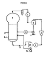
- Figure 1 is a schematic illustration of a fluidized bed reactor unit used to carry out the process of the present.
- the reactor unit shown includes a means for subcooling the pre-compressor liquids.
- the post-compressor liquids are entrained in the recycle stream as it returns to the reactor.
- Figure 2 is a schematic illustration of the fluidized bed reactor of the present invention for use in the embodiment of the process of the present invention comprising the separation and pumping of essentially all condensed liquids.
- the present invention includes an unexpectedly beneficial fluid bed cooling unit apparatus, not previously contemplated, for cooling, repressurizing the fluid stream, and reintroducing the recycle stream into the reactor as separate streams of gas and liquid.
- the invention has the advantage of minimizing total energy usage for repressurizing and of maximizing the approach of process temperatures to the temperature of the available coolant source.
- the continuous fluidized bed chemical process of the present invention comprises continuously passing a fluid stream comprising reactant monomer through a fluidized bed reactor in the presence of catalyst at reaction conditions of temperature, pressure, and fluid flow rate sufficient to form product. This continuous circulation is provided while continuously withdrawing said product from said reactor, and sufficiently introducing makeup monomer into said reactor.
- the reaction conditions of the present process are controlled by cooling at least a portion of the unreacted gas portion of said fluid stream by a cooling method comprising
- the present process would benefit the production of any polymer that can be made in fluidized bed reactors with the injection of volatile cooling liquids into the bed.
- suitable products include polyolefins, olefin copolymers with alpha-olefins or cyclo-olefins, and polymers made using vinyl monomers.
- any type of catalyst system is suitable for use in the present process, provided only that the catalyst system will function in a fluid bed reactor with the addition of volatile cooling liquids to the bed.
- the present process is suitable for use with any type of cooling liquids that can be condensed from the recycle stream for return to the reactor. This includes mixtures of the unreacted monomers and inert, volatile compounds. These volatile compounds may be added to the mixture expressly for the purpose of enhanced heat removal, or they may occur coincidentally due to feed stream impurities or due to side reactions occurring in the reactor loop.
- the fluid stream contains monomers including olefins, vinyl monomers, and a combination thereof.
- the fluidized monomers are more preferably olefins, alpha-olefins, cyclo-olefins, or a combination thereof, with ethylene, propylene, and alpha-olefins being most preferred.
- FIG. 1 schematically represents a preferred apparatus for carrying out the present process.
- unreacted monomers and inert compounds exit the reactor 5 and pass toward cooler 1 .
- Separating solids by use of separator 6 is optional. It may or not be advantageous depending on the catalyst, polymer and recycle compression and cooling technology being used. The presence or absence of separator 6 does not affect the novelty and utility of this invention.
- the process of the present invention is suitable for use with entrained solids in the recycle stream leaving reactor 5 .
- the two-phase (three-phase is solids are present) recycle stream then passes into a separator 2 where most of the free liquid is removed.
- the separator is preferably a cyclone separator.
- Pump 7 preferably pressurizes the condensed liquid from cooler 1 for addition to the fluid bed inside reactor 5 , where the volatile liquid vaporizes to provide reactor cooling.
- the liquids from pump 7 may be subcooled with liquid cooler 11 . This will remove energy imparted by inefficiencies in the pumping operation. Cooler 11 may also be useful whenever cooler 1 has insufficient heat exchange capacity to allow process temperature to approach closely to the temperature of the coolant supply. It is important that the liquid should vaporize within the bed under the polymerization conditions being employed so that the desired cooling effect is obtained and to avoid substantial accumulation of liquid within the bed. Specific techniques for introducing condensed liquid into the fluid bed for cooling are disclosed in Int. Pub. No. WO94/28032, incorporated herein in its entirety.
- the uncondensed portion of the recycle stream leaves separator 2 and enters a compressor 3 .
- Enough pressure energy must be imparted at the compressor to cause the recycle stream to circulate continuously.
- the compression operation inherently raises the temperature of the recycle stream. Any lost work on the process side of the compressor adds further to the temperature rise.
- the process of the present invention includes condensing the fluid at this point from the recycle stream.
- the higher pressure at this point makes is possible to condense additional liquids from the recycle stream, increasing the thermal efficiency of the process, reducing overall energy usage and reducing overall system costs.
- the liquids condensed in cooler 4 may be left in the main recycle stream.
- the combined two-phase flow (three-phase if solids are present) may be carried to the bottom of the reactor and introduced into the bed through the grid.
- Technology is well known in the art for entraining the liquid (and solids if present) in the gas flow.
- Figure 2 shows an alternate embodiment of the process of the present invention. It differs in that the multiphase flow from cooler 4 is passed into a separator 2A , with separated liquids being sent back to the reactor via pump 7A . These liquids may be combined with the liquids before or after cooler 1 , or the liquids may be injected separately to the fluidized bed.
- stream 8 represents makeup monomers, inert compounds and chain terminator compounds.
- Stream 9 indicates the withdrawal of solid polymer along with unreacted monomers, inert compounds and chain terminator compounds.
- Stream 10 indicates the injection of the catalyst system.
- Non-limiting examples of such other purposes include a recycle loop purge stream for composition control, motive gas for induction of fines or catalyst into the fluid bed, control of fluidization velocity through the reactor, control of gas phase composition at specific locations within the reactor, and establishment of unique circulation pattern within the reactor.
- Each of the equipment items shown as coolers 1 , 4 , and 11 may be multiple, physically separate units, such as multiple heat exchangers in parallel or series of both, even with different coolant temperatures, within the scope of the invention.
- Particular advantage may accrue to having two exchangers in series wherein the upstream exchanger uses a low cost coolant source, such as cooling water, to remove a large part of the heat duty and the second exchanger uses a refrigerated cooling source to condense even more liquids in the process stream.
- the fluid flow rate of the present process of preferably such to provide a superficial fluidization velocity through the reactor 30 to 100 cm per second, more preferably 50 to 90 cm per second.
- Superficial fluidization velocity is determined by dividing the velocity of gas in the reactor by the cross sectional area of the empty reactor.
- the unexpected benefits of the process of the present invention accrue from condensing cooling liquids both before and after compression of all or part of the recycle gas stream.
- the process of the present invention preferably provides a heat removal capacity of 1X10 5 to 1X10 8 kcal per hour, more preferably at least 1X10 6 kcal per hour.
- the heat removal of the present process is preferably to such an extent that the fluid bed temperature is maintained at a temperature of 20 to about 150° C, more preferably 40 to 120° C.
- the present invention further includes the cooled fluid bed reactor unit represented by Figure 1.
- This apparatus comprises a fluid bed reactor comprising a fluidization grid near the bottom of said reactor, an unreacted gas outlet at about the top of said reactor, a cooling and fluidizing fluid inlet below said fluidization grid, a liquid inlet above said fluidization grid, said unreacted gas outlet being connected to said cooling and fluidizing inlet and said liquid inlet by way of a cooling unit comprising a first cooler connected downstream to said unreacted gas outlet, said first cooler being further connected to a gas/liquid separator that is further connected to a compressor that is further connected to a second cooler that is further connected to said reactor cooling gas inlet, further wherein said gas/liquid separator is connected to a pressurizing pump that is further connected to a third cooler that is further connected to said liquid inlet, even further wherein said compressor is capable of providing enough pressure energy to continuously circulate fluid through said fluid bed reactor unit.
- This example illustrates the unexpectedly high increase in cooling capacity provided by the process of the present inventions as conducted using a preferred embodiment of the cooled fluid bed reactor unit of the present intervention.
- the process of the present invention was conducted using a cooled fluid bed reactor unit represented by the schematic diagram shown in Figure 2.
- the fluidized bed reactor was operated with a combined recycle flow of about 2.6 million pounds per hour (1.18 million Kg/hr).
- a copolymer of ethylene and hexene-1 was produced using a Ziegler catalyst.
- composition of the recycle stream entering cooler 1 is shown below Component Mole % methane 0.1 ethane 1.8 ethylene 27.8 C4 hydrocarbons 1.0 hexene-1 4.0 hexene-2 1.1 saturated C6 hydrocarbon 3.1 saturated hydrocarbon>C6 0.1 hydrogen 5.9 nitrogen 55.1
- Reactor outlet pressure was 315 psia (2.17 megapascal) at a temperature of 86° C.
- the recycle stream outlet from cooler 1 was cooled to 56° C, removing approximately 87 million BTU/hr (21.9 million kcal/hr).
- Approximately 11 weight percent of the recycle stream was condensed to liquid at the outlet of cooler 1 .
- This liquid was pumped to a pressure of 470 psia (3.24 megapascal) and discharged to cooler 11 using 120 horsepower (89 kilowatts) of mechanical power.
- the energy used to return the condensed liquid to the reactor was thus 1 BTU per pound (0.56 kcal/kg) of process fluid.
- cooler 11 an additional 6 million BTU/hr (1.5 million kcal/hr) of sensible heat was removed by sub-cooling the condensed liquid mixture to 38° C.
- the pressure at the inlet to cooler 4 was raised to 330 psia (2.28 megapascal) by compressor 3 , using 6,500 horsepower (4,850 kw) of mechanical power.
- the energy used to return from the overhead of separator 2 to the reactor was thus about 7 BTU per pound (3.89 kcal/kg) of process fluid, 7 times more than for the liquid returned from the bottom of separator 2 .
- the power required in compressor 3 is about 10 percent less than if the remaining gas stream from atop separator 2 were compressed beginning at a suction temperature of 86° C. This further reduces the size and capital cost of compressor 3 , the cost for compressor power, and the amount of total heat that must be removed in coolers 1 , 4 , and 11 .
- the total heat removal of 139 million BTU/hr (35.0 million kcal/hr) enabled the production of 83,600 lb/hr (37,900 kg/hr) of the ethylene-hexene copolymer, significantly more than would have been produced if the liquids were not condensed in coolers on both the suction and discharge of the compressor.
Landscapes
- Chemical & Material Sciences (AREA)
- Chemical Kinetics & Catalysis (AREA)
- Organic Chemistry (AREA)
- Engineering & Computer Science (AREA)
- Combustion & Propulsion (AREA)
- Health & Medical Sciences (AREA)
- Medicinal Chemistry (AREA)
- Polymers & Plastics (AREA)
- Polymerisation Methods In General (AREA)
- Devices And Processes Conducted In The Presence Of Fluids And Solid Particles (AREA)
Abstract
Description
- The present invention relates to continuous fluidized bed chemical reactors. The present invention further relates to a process of cooling the reactor contents during fluid bed polymerization. More particularly, the present invention relates to a process of withdrawing an increased amount of heat from recirculating fluidizing gas before being reintroduced into the reactor.
- It is well know that many polymers can be exothermically produced as powders in fluidized bed reactors wherein the fluidization is provided by a circulating mixture of gases that includes the monomers. It is known that the fluidizing gases leaving the reactor can be recirculated with cooling before reintroduction to the reactor in order to remove the heat of reaction and keep the fluid bed temperature near a desired temperature. Further, it is known that a portion of the recirculating stream may be condensed in coolers (heat exchangers) before re-insertion into the reactor. It is advantageous to remove the latent heat of vaporization, in addition to the sensible heat accumulated in the gas, since the latent heat of vaporization may be much larger per degree of cooling than the sensible heat of the uncondensed stream.
- A variety of methods are used for reintroduction of the cooled recycle gas and liquids to the reactor. Often, most of the cooled recycle gas is injected into the reactor through a distributor plate below the fluid bed. The condensed recycle liquids may be entrained in the recycle gas or injected directly into the bed through some sort of nozzle assembly. Examples of the above technologies are shown in U. S. Patents 3,595,840, 4,543,399, 4,588,790, 5,352,749, and International Publication WO 94/28032.
- A compressor is used to continuously suction the fluidizing gas up out of the reactor so that it can travel through a cooling unit prior to being reinserted into the bottom of the reactor. Int. Pub. WO 94/28032 discloses the efficiencies of condensing a portion of the gas stream and removing the liquid produced therefrom prior to compression of the remaining gaseous recycle stream. Noting that the compressor action adds an additional amount of heat to the recycle stream, Int. Pub. WO 94/28032 further discloses an advantage in cooling the recycle gas again after compression to remove the heat of compression.
- Since the rate of fluid bed polymer production is limited by the temperature inside the fluid bed reactor, the rate of polymer production can be increased as more cooling is provided to the reactor. In light of the above, it would be desirable to provide a continuous fluid bed polymerization process including a method for withdrawing a higher amount of heat from the fluid recycle stream.
- The continuous fluidized bed chemical process of the present invention comprises continuously passing a fluid stream comprising reactant monomers through a fluid bed reactor in the presence of a catalyst at reaction conditions of temperature, pressure, and a fluid flow rate sufficient to form product, withdrawing said product from said reactor, sufficiently introducing makeup monomer into said reactor, said reaction conditions being controlled by cooling at least a portion of the unreacted gas portion of said fluid stream by a cooling method comprising
- a) cooling said gas sufficiently to condense a portion of said gas to a liquid,
- b) thereafter separating said liquid from said cooled gas,
- c) compressing said cooled gas,
- d) thereafter recooling said cooled and compressed gas sufficiently to condense a portion thereof to a liquid,
- e) reintroducing said liquid portions and said recooled gas into said reactor sufficiently to maintain reactive conditions.
-
- Figure 1 is a schematic illustration of a fluidized bed reactor unit used to carry out the process of the present. The reactor unit shown includes a means for subcooling the pre-compressor liquids. Using the apparatus shown, the post-compressor liquids are entrained in the recycle stream as it returns to the reactor.
- Figure 2 is a schematic illustration of the fluidized bed reactor of the present invention for use in the embodiment of the process of the present invention comprising the separation and pumping of essentially all condensed liquids.
- The applicants were surprised to find a cooling method whereby a relatively small increase in condenser energy capital, when applied to a particular area in the recycle stream, provides an unexpectedly large increasing in the amount of heat withdrawn from the recycle stream. This process thereby provides an unexpectedly large increase in polymer product production rate.
- While Int. Pub. WO 94/28032 discloses the benefit of removing the heat of compression from the fluid stream prior to being reintroduced into the reactor, it was unexpected to find that by providing an increased amount of cooling at the post-compression cooler, in addition to the amount of cooling required to remove the heat of compression, that the polymer production rate is increased by a tremendously beneficial amount. The applicants have found that, since the compression operation raises the dew point temperature of the recycle stream, it is unexpectedly efficient to remove the latent heat of vaporization after compression, thereby forming a liquid both before and after compression. The increased dew point temperature and condensation of additional liquids allow an important increase in cooling capacity.
- In addition, the present invention includes an unexpectedly beneficial fluid bed cooling unit apparatus, not previously contemplated, for cooling, repressurizing the fluid stream, and reintroducing the recycle stream into the reactor as separate streams of gas and liquid. The invention has the advantage of minimizing total energy usage for repressurizing and of maximizing the approach of process temperatures to the temperature of the available coolant source.
- The continuous fluidized bed chemical process of the present invention comprises continuously passing a fluid stream comprising reactant monomer through a fluidized bed reactor in the presence of catalyst at reaction conditions of temperature, pressure, and fluid flow rate sufficient to form product. This continuous circulation is provided while continuously withdrawing said product from said reactor, and sufficiently introducing makeup monomer into said reactor. The reaction conditions of the present process are controlled by cooling at least a portion of the unreacted gas portion of said fluid stream by a cooling method comprising
- a) cooling said gas sufficiently to condense a portion of said gas to a liquid,
- b) thereafter separating said liquid from said cooled gas,
- c) compressing said cooled gas,
- d) thereafter recooling said cooled and compressed gas sufficiently to condense a portion thereof to a liquid,
- e) reintroducing said liquid portions and said recooled gas into said reactor sufficiently to maintain reactive conditions.
-
- The present process would benefit the production of any polymer that can be made in fluidized bed reactors with the injection of volatile cooling liquids into the bed. Though not limited to any particular type of polymer, suitable products include polyolefins, olefin copolymers with alpha-olefins or cyclo-olefins, and polymers made using vinyl monomers. Generally any type of catalyst system is suitable for use in the present process, provided only that the catalyst system will function in a fluid bed reactor with the addition of volatile cooling liquids to the bed. Further the present process is suitable for use with any type of cooling liquids that can be condensed from the recycle stream for return to the reactor. This includes mixtures of the unreacted monomers and inert, volatile compounds. These volatile compounds may be added to the mixture expressly for the purpose of enhanced heat removal, or they may occur coincidentally due to feed stream impurities or due to side reactions occurring in the reactor loop.
- In the preferred process of the present invention, the fluid stream contains monomers including olefins, vinyl monomers, and a combination thereof. The fluidized monomers are more preferably olefins, alpha-olefins, cyclo-olefins, or a combination thereof, with ethylene, propylene, and alpha-olefins being most preferred.
- The process of the present invention is not limited to any particular apparatus or piping details for the process operations described. Suitable hardware is known in the art for all the operations described herein. Figure 1 schematically represents a preferred apparatus for carrying out the present process. With reference to Figure 1, in process of the present invention, unreacted monomers and inert compounds exit the
reactor 5 and pass towardcooler 1. Separating solids by use ofseparator 6 is optional. It may or not be advantageous depending on the catalyst, polymer and recycle compression and cooling technology being used. The presence or absence ofseparator 6 does not affect the novelty and utility of this invention. The process of the present invention is suitable for use with entrained solids in the recyclestream leaving reactor 5. - At cooler 1, sufficient heat is removed in order to condense a portion of the recycle stream. The two-phase (three-phase is solids are present) recycle stream then passes into a
separator 2 where most of the free liquid is removed. The separator is preferably a cyclone separator. -
Pump 7 preferably pressurizes the condensed liquid from cooler 1 for addition to the fluid bed insidereactor 5, where the volatile liquid vaporizes to provide reactor cooling. Optionally, the liquids frompump 7 may be subcooled withliquid cooler 11. This will remove energy imparted by inefficiencies in the pumping operation.Cooler 11 may also be useful whenever cooler 1 has insufficient heat exchange capacity to allow process temperature to approach closely to the temperature of the coolant supply. It is important that the liquid should vaporize within the bed under the polymerization conditions being employed so that the desired cooling effect is obtained and to avoid substantial accumulation of liquid within the bed. Specific techniques for introducing condensed liquid into the fluid bed for cooling are disclosed in Int. Pub. No. WO94/28032, incorporated herein in its entirety. - The uncondensed portion of the recycle stream leaves
separator 2 and enters acompressor 3. Enough pressure energy must be imparted at the compressor to cause the recycle stream to circulate continuously. The compression operation inherently raises the temperature of the recycle stream. Any lost work on the process side of the compressor adds further to the temperature rise. - Upon exiting
compressor 3, the compressed gas passes into asecond cooler 4. Rather than simply removing the heat of compression, the process of the present invention includes condensing the fluid at this point from the recycle stream. The higher pressure at this point makes is possible to condense additional liquids from the recycle stream, increasing the thermal efficiency of the process, reducing overall energy usage and reducing overall system costs. As shown in Figure 1, the liquids condensed incooler 4 may be left in the main recycle stream. The combined two-phase flow (three-phase if solids are present) may be carried to the bottom of the reactor and introduced into the bed through the grid. Technology is well known in the art for entraining the liquid (and solids if present) in the gas flow. - Figure 2 shows an alternate embodiment of the process of the present invention. It differs in that the multiphase flow from cooler 4 is passed into a
separator 2A, with separated liquids being sent back to the reactor viapump 7A. These liquids may be combined with the liquids before or after cooler 1, or the liquids may be injected separately to the fluidized bed. - In both figures,
stream 8 represents makeup monomers, inert compounds and chain terminator compounds.Stream 9 indicates the withdrawal of solid polymer along with unreacted monomers, inert compounds and chain terminator compounds.Stream 10 indicates the injection of the catalyst system. For each of these streams, there are various methods and locations known in the art for addition either to the reactor or to the recycle stream flow. Particular advantages and disadvantages accrue to the particular methods and locations, but the particular methods and location do not impede the novelty or utility of the current invention. - In like manner, diversion of part of the recycle stream flow to purposes other than cooling is included in the present process. Non-limiting examples of such other purposes include a recycle loop purge stream for composition control, motive gas for induction of fines or catalyst into the fluid bed, control of fluidization velocity through the reactor, control of gas phase composition at specific locations within the reactor, and establishment of unique circulation pattern within the reactor.
- Each of the equipment items shown as
coolers - The fluid flow rate of the present process of preferably such to provide a superficial fluidization velocity through the reactor 30 to 100 cm per second, more preferably 50 to 90 cm per second. Superficial fluidization velocity is determined by dividing the velocity of gas in the reactor by the cross sectional area of the empty reactor.
- The unexpected benefits of the process of the present invention accrue from condensing cooling liquids both before and after compression of all or part of the recycle gas stream. The process of the present invention preferably provides a heat removal capacity of 1X10⁵ to 1X10⁸ kcal per hour, more preferably at least 1X10⁶ kcal per hour. The heat removal of the present process is preferably to such an extent that the fluid bed temperature is maintained at a temperature of 20 to about 150° C, more preferably 40 to 120° C.
- The present invention further includes the cooled fluid bed reactor unit represented by Figure 1. This apparatus comprises a fluid bed reactor comprising a fluidization grid near the bottom of said reactor, an unreacted gas outlet at about the top of said reactor, a cooling and fluidizing fluid inlet below said fluidization grid, a liquid inlet above said fluidization grid, said unreacted gas outlet being connected to said cooling and fluidizing inlet and said liquid inlet by way of a cooling unit comprising a first cooler connected downstream to said unreacted gas outlet, said first cooler being further connected to a gas/liquid separator that is further connected to a compressor that is further connected to a second cooler that is further connected to said reactor cooling gas inlet, further wherein said gas/liquid separator is connected to a pressurizing pump that is further connected to a third cooler that is further connected to said liquid inlet, even further wherein said compressor is capable of providing enough pressure energy to continuously circulate fluid through said fluid bed reactor unit.
- The following example is intended to further illustrate the present invention, but should not be construed as a limitation thereon.
- This example illustrates the unexpectedly high increase in cooling capacity provided by the process of the present inventions as conducted using a preferred embodiment of the cooled fluid bed reactor unit of the present intervention. The process of the present invention was conducted using a cooled fluid bed reactor unit represented by the schematic diagram shown in Figure 2. The fluidized bed reactor was operated with a combined recycle flow of about 2.6 million pounds per hour (1.18 million Kg/hr). A copolymer of ethylene and hexene-1 was produced using a Ziegler catalyst. The composition of the recycle stream entering cooler 1 is shown below
Component Mole % methane 0.1 ethane 1.8 ethylene 27.8 C4 hydrocarbons 1.0 hexene-1 4.0 hexene-2 1.1 saturated C6 hydrocarbon 3.1 saturated hydrocarbon>C6 0.1 hydrogen 5.9 nitrogen 55.1 - Reactor outlet pressure was 315 psia (2.17 megapascal) at a temperature of 86° C. The recycle stream outlet from cooler 1 was cooled to 56° C, removing approximately 87 million BTU/hr (21.9 million kcal/hr). Approximately 11 weight percent of the recycle stream was condensed to liquid at the outlet of
cooler 1. This liquid was pumped to a pressure of 470 psia (3.24 megapascal) and discharged to cooler 11 using 120 horsepower (89 kilowatts) of mechanical power. The energy used to return the condensed liquid to the reactor was thus 1 BTU per pound (0.56 kcal/kg) of process fluid. In cooler 11, an additional 6 million BTU/hr (1.5 million kcal/hr) of sensible heat was removed by sub-cooling the condensed liquid mixture to 38° C. - The pressure at the inlet to cooler 4 was raised to 330 psia (2.28 megapascal) by
compressor 3, using 6,500 horsepower (4,850 kw) of mechanical power. The energy used to return from the overhead ofseparator 2 to the reactor was thus about 7 BTU per pound (3.89 kcal/kg) of process fluid, 7 times more than for the liquid returned from the bottom ofseparator 2. - The power required in
compressor 3 is about 10 percent less than if the remaining gas stream from atopseparator 2 were compressed beginning at a suction temperature of 86° C. This further reduces the size and capital cost ofcompressor 3, the cost for compressor power, and the amount of total heat that must be removed incoolers - Energy loss in highly turbulent flow is known to vary approximately with the square of the mass flow rate. Therefore 11 weight % of the mass at
separator 2 was removed, reducing the subsequent flowing pressure loss in the main recycle stream by about 23 %. With the facilities particular to this example, the flowing pressure losses were reduced by about 2 psia (0.014 megapascal) fromseparator 2 into the fluidized bed ofreactor 5. This represented a further savings in compression energy of 5%, again reducing costs forcompressor 2, compressor power andcoolers - About 46 million BTU/hr (11. million kcal/hr) of heat were removed in
cooler 4, where the coolant supply temperature limited the process temperature to about 44° C. It is important to note that if no condensation were practiced in this exchanger, heat removal would have been limited to about 7 million BTU/hr (1.8 million kcal/hr), significantly reducing the amount of polymer produced. - In the example shown above, the total heat removal of 139 million BTU/hr (35.0 million kcal/hr) enabled the production of 83,600 lb/hr (37,900 kg/hr) of the ethylene-hexene copolymer, significantly more than would have been produced if the liquids were not condensed in coolers on both the suction and discharge of the compressor.
Claims (18)
- A continuous fluidized bed chemical process comprising:
continuously passing a fluid stream comprising reactant monomers through a fluidized bed reactor in the presence of a catalyst at reaction conditions of temperature, pressure, and a fluid flow rate sufficient to form product, withdrawing said product from said reactor, sufficiently introducing makeup monomer into said reactor, said reaction conditions being controlled by cooling at least a portion of the unreacted gas portion of said fluid stream by a cooling method comprisinga) cooling said gas sufficiently to condense a portion of said gas to a liquid,b) thereafter separating said liquid from said cooled gas,c) compressing said cooled gas,d) thereafter recooling said cooled and compressed gas sufficiently to condense a portion thereof to a liquid,e) reintroducing said liquid portions and said recooled gas into said reactor sufficiently to maintain reactive conditions. - The process of claim 1 wherein said liquid formed upon recooling step d) is entrained in said gas when reintroduced into said reactor.
- The process of claim 1 wherein said liquid formed upon recooling step d) is separated from said gas prior to being reintroduced into said reactor.
- The process of claim 1 wherein said separated liquid obtained in step b) is pressurized prior to being reintroduced into said reactor.
- The process of claim 1 further wherein, after being separated from said gas, in step b) said liquid is further cooled.
- The process of claim 1 wherein said makeup monomer is introduced into said reactor by being added to said unreacted gas portion of said fluid stream.
- The process of claim 1 further wherein said cooling method further comprises separating entrained solids away from said gas stream.
- The process of claim 1 wherein said monomers are selected from the group consisting of olefins, vinyl monomers, and a combination thereof.
- The process of claim 8 wherein said monomers are selected from the group consisting of olefins, alpha-olefins, cyclo-olefins and a combination thereof.
- The process of claim 9 wherein said monomers are a combination of ethylene, propylene, and alpha-olefins.
- The process of claim 1 wherein a portion of said unreacted gas portion of said fluid stream is diverted to a process operation other than cooling, said process operation being selected form the group consisting of a loop purge stream, motive gas for introduction of materials into said reactor, control of fluid flow rate, control of gas phase composition, circulation control, and a combination thereof.
- The process of claim 1 wherein the heat removal capacity is 1X10⁵ to 1X10⁸ kcal per hour.
- The process of claim 1 wherein said fluid flow rate provides a superficial fluidization velocity through the reactor, determined by dividing the velocity of gas in the reactor by the cross sectional area of the empty reactor, of 30 to 100 cm per second.
- The process of claim 1 wherein the reaction temperature in said fluidized bed is maintained at a temperature of from 20 to 150° C.
- The process of claim 14 having a fluid bed reaction temperature of 40 to 120° C.
- A cooled fluidized bed reactor unit comprising:
a fluidized bed reactor comprising a fluidization grid near the bottom of said reactor, an unreacted gas outlet at about the top of said reactor, a cooling and fluidizing fluid inlet below said fluidization grid, a liquid inlet above said fluidization grid, said unreacted gas outlet being connected to said cooling and fluidizing inlet and said liquid inlet by way of a cooling unit comprising a first cooler connected downstream to said unreacted gas outlet, said first cooler being further connected to a gas/liquid separator that is further connected to a compressor that is further connected to a second cooler that is further connected to said reactor cooling gas inlet. - A cooled fluidized bed reactor unit according to claim 16, wherein said gas/liquid separator is also connected to a pressurizing pump that is further connected to a third cooler that is further connected to said liquid inlet.
- A cooled fluidized bed reactor unit according to claim 16, wherein said compressor is capable of providing enough pressure energy to continuously circulate fluid through said fluidized bed reactor unit.
Applications Claiming Priority (5)
| Application Number | Priority Date | Filing Date | Title |
|---|---|---|---|
| US2867096P | 1996-10-17 | 1996-10-17 | |
| US28670P | 1996-10-17 | ||
| US951597 | 1997-10-16 | ||
| US08/951,597 US6111036A (en) | 1996-10-17 | 1997-10-16 | Method for improving cooling of fluid bed polymer reactor |
| PCT/US1997/019085 WO1998016562A1 (en) | 1996-10-17 | 1997-10-17 | Method for improved cooling of fluid bed polymer reactor |
Publications (2)
| Publication Number | Publication Date |
|---|---|
| EP0932627A1 EP0932627A1 (en) | 1999-08-04 |
| EP0932627B1 true EP0932627B1 (en) | 2001-01-03 |
Family
ID=26703960
Family Applications (1)
| Application Number | Title | Priority Date | Filing Date |
|---|---|---|---|
| EP97912853A Expired - Lifetime EP0932627B1 (en) | 1996-10-17 | 1997-10-17 | Method for improved cooling of fluidized bed polymer reactor |
Country Status (5)
| Country | Link |
|---|---|
| US (1) | US6111036A (en) |
| EP (1) | EP0932627B1 (en) |
| BR (1) | BR9711932A (en) |
| DE (1) | DE69703846T2 (en) |
| WO (1) | WO1998016562A1 (en) |
Families Citing this family (19)
| Publication number | Priority date | Publication date | Assignee | Title |
|---|---|---|---|---|
| US6218484B1 (en) * | 1999-01-29 | 2001-04-17 | Union Carbide Chemicals & Plastics Technology Corporation | Fluidized bed reactor and polymerization process |
| GB0014584D0 (en) * | 2000-06-14 | 2000-08-09 | Bp Chem Int Ltd | Apparatus and process |
| US6489408B2 (en) * | 2000-11-30 | 2002-12-03 | Univation Technologies, Llc | Polymerization process |
| ES2304403T3 (en) * | 2001-12-20 | 2008-10-16 | UNION CARBIDE CHEMICALS & PLASTICS TECHNOLOGY CORPORATION | PRODUCTION OF HIGH CONDENSATION POLYOLEFINS IN TURBULENT CONDITIONS IN A FLUIDIZED MILK. |
| US7406839B2 (en) * | 2005-10-05 | 2008-08-05 | American Power Conversion Corporation | Sub-cooling unit for cooling system and method |
| US7365973B2 (en) | 2006-01-19 | 2008-04-29 | American Power Conversion Corporation | Cooling system and method |
| US8672732B2 (en) * | 2006-01-19 | 2014-03-18 | Schneider Electric It Corporation | Cooling system and method |
| US9568206B2 (en) | 2006-08-15 | 2017-02-14 | Schneider Electric It Corporation | Method and apparatus for cooling |
| US8327656B2 (en) | 2006-08-15 | 2012-12-11 | American Power Conversion Corporation | Method and apparatus for cooling |
| US8322155B2 (en) | 2006-08-15 | 2012-12-04 | American Power Conversion Corporation | Method and apparatus for cooling |
| US7681404B2 (en) | 2006-12-18 | 2010-03-23 | American Power Conversion Corporation | Modular ice storage for uninterruptible chilled water |
| US8425287B2 (en) | 2007-01-23 | 2013-04-23 | Schneider Electric It Corporation | In-row air containment and cooling system and method |
| JP5559040B2 (en) | 2007-05-15 | 2014-07-23 | シュナイダー エレクトリック アイティー コーポレーション | Method and system for managing power and cooling of equipment |
| US20090030554A1 (en) * | 2007-07-26 | 2009-01-29 | Bean Jr John H | Cooling control device and method |
| US8219362B2 (en) | 2009-05-08 | 2012-07-10 | American Power Conversion Corporation | System and method for arranging equipment in a data center |
| US9394381B2 (en) | 2010-11-29 | 2016-07-19 | Ineos Sales (Uk) Limited | Polymerisation control process |
| US8688413B2 (en) | 2010-12-30 | 2014-04-01 | Christopher M. Healey | System and method for sequential placement of cooling resources within data center layouts |
| CN104137660B (en) | 2011-12-22 | 2017-11-24 | 施耐德电气It公司 | System and method for the predicting temperature values in electronic system |
| AU2011384046A1 (en) | 2011-12-22 | 2014-07-17 | Schneider Electric It Corporation | Analysis of effect of transient events on temperature in a data center |
Family Cites Families (7)
| Publication number | Priority date | Publication date | Assignee | Title |
|---|---|---|---|---|
| US3595840A (en) * | 1968-11-25 | 1971-07-27 | Phillips Petroleum Co | Control of particle size in vinyl monomer polymerization |
| US4543399A (en) * | 1982-03-24 | 1985-09-24 | Union Carbide Corporation | Fluidized bed reaction systems |
| US4588790A (en) * | 1982-03-24 | 1986-05-13 | Union Carbide Corporation | Method for fluidized bed polymerization |
| US4640963A (en) * | 1985-02-15 | 1987-02-03 | Standard Oil Company (Indiana) | Method and apparatus for recycle of entrained solids in off-gas from a gas-phase polyolefin reactor |
| US5352749A (en) * | 1992-03-19 | 1994-10-04 | Exxon Chemical Patents, Inc. | Process for polymerizing monomers in fluidized beds |
| ZA943399B (en) * | 1993-05-20 | 1995-11-17 | Bp Chem Int Ltd | Polymerisation process |
| US5376742A (en) * | 1993-09-23 | 1994-12-27 | Quantum Chemical Corporation | Monomer recovery in gas phase fluid bed olefin polymerization |
-
1997
- 1997-10-16 US US08/951,597 patent/US6111036A/en not_active Expired - Lifetime
- 1997-10-17 EP EP97912853A patent/EP0932627B1/en not_active Expired - Lifetime
- 1997-10-17 WO PCT/US1997/019085 patent/WO1998016562A1/en not_active Ceased
- 1997-10-17 BR BR9711932-6A patent/BR9711932A/en not_active IP Right Cessation
- 1997-10-17 DE DE69703846T patent/DE69703846T2/en not_active Expired - Lifetime
Also Published As
| Publication number | Publication date |
|---|---|
| BR9711932A (en) | 2000-05-09 |
| DE69703846D1 (en) | 2001-02-08 |
| DE69703846T2 (en) | 2001-04-26 |
| WO1998016562A1 (en) | 1998-04-23 |
| EP0932627A1 (en) | 1999-08-04 |
| US6111036A (en) | 2000-08-29 |
Similar Documents
| Publication | Publication Date | Title |
|---|---|---|
| US6111036A (en) | Method for improving cooling of fluid bed polymer reactor | |
| US7741430B2 (en) | Polymerisation process | |
| US6218484B1 (en) | Fluidized bed reactor and polymerization process | |
| US5521264A (en) | Gas phase olefin polymerization process with recovery of monomers from reactor vent gas by absorption | |
| US8697819B2 (en) | System for producing steam using heat recovered from a polymerization reaction | |
| KR101144695B1 (en) | Method for cooling in distillation and polymerisation process by absorption refrigeration | |
| CN105199031B (en) | A kind of olefine polymerizing process and device | |
| CZ289037B6 (en) | Polymerization process | |
| CN110997731B (en) | Polymerization process comprising discharging polyolefin particles from a gas phase polymerization reactor | |
| CN109715678A (en) | Integrated dehydrogenating propane method | |
| CN101378832B (en) | Method for Converting a Loop Reactor | |
| CN107303478A (en) | Fluidized-bed reactor, olefinic polymerization device and olefine polymerizing process | |
| CA2212787A1 (en) | Method for avoiding heat-exchanger fouling in a fluidized-bed polymerization process | |
| CN112300312A (en) | Synthetic method of polyethylene | |
| US5266276A (en) | Apparatus for the gas-phase polymerization of olefins in a fluidized-bed reactor | |
| CN116143963A (en) | Method for producing polymers | |
| US20240343839A1 (en) | Gas phase polymerization process with improved gas recycling | |
| CN102234340B (en) | Olefin polymerization reaction apparatus and method | |
| CN116547308A (en) | Propylene polymerization apparatus and propylene polymerization method | |
| KR20260010733A (en) | Method for controlling the production rate of propylene homopolymer or copolymer in a gas phase reactor |
Legal Events
| Date | Code | Title | Description |
|---|---|---|---|
| PUAI | Public reference made under article 153(3) epc to a published international application that has entered the european phase |
Free format text: ORIGINAL CODE: 0009012 |
|
| 17P | Request for examination filed |
Effective date: 19990408 |
|
| AK | Designated contracting states |
Kind code of ref document: A1 Designated state(s): DE FR GB |
|
| RTI1 | Title (correction) |
Free format text: METHOD FOR IMPROVED COOLING OF FLUIDIZED BED POLYMER REACTOR |
|
| GRAG | Despatch of communication of intention to grant |
Free format text: ORIGINAL CODE: EPIDOS AGRA |
|
| RTI1 | Title (correction) |
Free format text: METHOD FOR IMPROVED COOLING OF FLUIDIZED BED POLYMER REACTOR |
|
| RTI1 | Title (correction) |
Free format text: METHOD FOR IMPROVED COOLING OF FLUIDIZED BED POLYMER REACTOR |
|
| 17Q | First examination report despatched |
Effective date: 19991130 |
|
| GRAG | Despatch of communication of intention to grant |
Free format text: ORIGINAL CODE: EPIDOS AGRA |
|
| GRAH | Despatch of communication of intention to grant a patent |
Free format text: ORIGINAL CODE: EPIDOS IGRA |
|
| GRAH | Despatch of communication of intention to grant a patent |
Free format text: ORIGINAL CODE: EPIDOS IGRA |
|
| GRAA | (expected) grant |
Free format text: ORIGINAL CODE: 0009210 |
|
| AK | Designated contracting states |
Kind code of ref document: B1 Designated state(s): DE FR GB |
|
| REF | Corresponds to: |
Ref document number: 69703846 Country of ref document: DE Date of ref document: 20010208 |
|
| ET | Fr: translation filed | ||
| PLBE | No opposition filed within time limit |
Free format text: ORIGINAL CODE: 0009261 |
|
| STAA | Information on the status of an ep patent application or granted ep patent |
Free format text: STATUS: NO OPPOSITION FILED WITHIN TIME LIMIT |
|
| REG | Reference to a national code |
Ref country code: GB Ref legal event code: IF02 |
|
| 26N | No opposition filed | ||
| REG | Reference to a national code |
Ref country code: GB Ref legal event code: 732E |
|
| REG | Reference to a national code |
Ref country code: FR Ref legal event code: TP |
|
| REG | Reference to a national code |
Ref country code: FR Ref legal event code: PLFP Year of fee payment: 20 |
|
| PGFP | Annual fee paid to national office [announced via postgrant information from national office to epo] |
Ref country code: FR Payment date: 20160919 Year of fee payment: 20 |
|
| PGFP | Annual fee paid to national office [announced via postgrant information from national office to epo] |
Ref country code: GB Payment date: 20161012 Year of fee payment: 20 Ref country code: DE Payment date: 20161011 Year of fee payment: 20 |
|
| REG | Reference to a national code |
Ref country code: DE Ref legal event code: R071 Ref document number: 69703846 Country of ref document: DE |
|
| REG | Reference to a national code |
Ref country code: GB Ref legal event code: PE20 Expiry date: 20171016 |
|
| PG25 | Lapsed in a contracting state [announced via postgrant information from national office to epo] |
Ref country code: GB Free format text: LAPSE BECAUSE OF EXPIRATION OF PROTECTION Effective date: 20171016 |