EP0932478B1 - An improved striking tool - Google Patents
An improved striking tool Download PDFInfo
- Publication number
- EP0932478B1 EP0932478B1 EP97917707A EP97917707A EP0932478B1 EP 0932478 B1 EP0932478 B1 EP 0932478B1 EP 97917707 A EP97917707 A EP 97917707A EP 97917707 A EP97917707 A EP 97917707A EP 0932478 B1 EP0932478 B1 EP 0932478B1
- Authority
- EP
- European Patent Office
- Prior art keywords
- head
- handle
- claw
- hammer
- central plate
- Prior art date
- Legal status (The legal status is an assumption and is not a legal conclusion. Google has not performed a legal analysis and makes no representation as to the accuracy of the status listed.)
- Expired - Lifetime
Links
Images


Classifications
-
- B—PERFORMING OPERATIONS; TRANSPORTING
- B25—HAND TOOLS; PORTABLE POWER-DRIVEN TOOLS; MANIPULATORS
- B25D—PERCUSSIVE TOOLS
- B25D1/00—Hand hammers; Hammer heads of special shape or materials
- B25D1/04—Hand hammers; Hammer heads of special shape or materials with provision for withdrawing or holding nails or spikes
-
- B—PERFORMING OPERATIONS; TRANSPORTING
- B25—HAND TOOLS; PORTABLE POWER-DRIVEN TOOLS; MANIPULATORS
- B25D—PERCUSSIVE TOOLS
- B25D1/00—Hand hammers; Hammer heads of special shape or materials
-
- B—PERFORMING OPERATIONS; TRANSPORTING
- B25—HAND TOOLS; PORTABLE POWER-DRIVEN TOOLS; MANIPULATORS
- B25G—HANDLES FOR HAND IMPLEMENTS
- B25G3/00—Attaching handles to the implements
- B25G3/36—Lap joints; Riveted, screwed, or like joints
Definitions
- the present invention is in the area of hand-held striking tools, such as hammers and pickaxes, and pertains more specifically to joining handles and heads for such tools, accommodating a demand for a variety of weights for such tools, and improving claw hammer versatility.
- Hand-held striking tools such as claw hammers, mallets, sledge hammers, ball peen hammers, masonry hammers, pickaxes, and the like, have been used by people in a variety of disciplines for centuries as leveraged devices to provide a striking force to accomplish a seemingly endless variety of tasks.
- a claw hammer commonly weighing from 7 to 32 ounces is used by people doing carpentry work to deliver sufficient striking force to drive a nail into wood.
- a claw hammer is also used for removing a nail or ripping apart lumber using it's claw.
- a sledge hammer commonly weighing from 2 to 20 pounds, is used to deliver sufficient striking force for heavy work such as driving a stake, rawl drill, chisel, or driving a wedge into masonry, stone, wood, or other hard materials.
- Another common hand-held striking tool is a ball peen hammer, which has a substantially flat surface on one end and a rounded surface on the other end of its head, and is used to deliver sufficient striking force for shaping and fitting metal, and for driving machine chisels, rivet sets, machine wedges, and other similar tools.
- a pickaxe is another example of a hand-held striking tool which is commonly used for loosening hard dirt and stones, and also used as a lever for prying heavy objects from the ground.
- Another common hand-held striking tool is a mallet, which is usually made of wood, plastic, rubber, or soft iron. A mallet provides a striking force to drive chisels or shape metal and other materials without significantly marring the material it strikes.
- Hand-held striking tools such as those described above, are commonly used as third-class levers used to provide a striking force to accomplish tasks such as driving a nail into a piece of wood, bending or forming metal, breaking a rock, and other similar tasks.
- Third class levers are levers where a fulcrum, also :referred to as a pivot point, is at one end of a bar or rod.
- a load to be overcome is an object creating resistance at the opposite end of a bar or rod.
- An effort, or force, to be applied to a third-class lever is somewhere in between a fulcrum and load.
- the fulcrum is a wrist
- the force is provided by deceleration of the movement of a hammer handle (bar or rod) at the wrist
- the load is a resistance presented by a piece of wood into which the nail is being driven.
- a hand-held striking tool such as a pickaxe
- the fulcrum is also a wrist
- the force is provided deceleration of the movement of a pickaxe handle (rod) at the wrist
- the load is a resistance presented by dirt or stones into which the sharp point of the pickaxe is driven.
- the head of a hand-held striking device is commonly a significant distance from the fulcrum and moves faster than the movement being applied at a user's hand, which is near the fulcrum.
- the increased speed of the head multiplies the applied force with which a striking device head strikes a nail or digs into the dirt.
- This principle applies to all other hand-held striking devices, and is intensified in long-handled striking devices such as a pickaxe or an axe.
- Hand-held striking tools are also commonly used as first-class levers to provide a lifting or prying force to accomplish a variety of tasks. For example, some hand-held striking devices are used to pull nails out of a pieces of wood, tear apart pieces of wood or other building material, pry loose a large rock, lift a log, and the like.
- First class levers are levers wherein he load to be overcome is at or near one end of a rod or bar, the effort, or force is applied at or near the other end of the same rod or bar, and the fulcrum, or pivot, is somewhere along the rod or bar in between the applied force and load.
- An example of a hand-held striking tool being used as a first class lever is a claw hammer being used to pull out nails, wherein the load to be overcome is the wood causing friction against an embedded nail.
- Another example of a hand-held striking tool being used as a first class lever is a pickaxe being used to pry out a rock or tree root embedded in dirt or rock, where the load to be overcome is the dirt or rock causing friction against an embedded rock or tree root.
- the load for a hand-held striking tool being used as a first class lever is typically very close to the fulcrum.
- the force for a hand-held striking tool being used as a third class lever is typically relatively far away from the fulcrum.
- the load applied is therefore moved less distance than the hand, which is at the opposite end of the lever, and applying the force. This multiplies the force in which the claw hammer head pulls against a nail, or a pickaxe pulls against a rock.
- the weakest part of a hand-held striking device is the interface between the handle and the head.
- the conventional method of interfacing a striking device head and handle which are typically made of distinct materials, such as metal and wood, allows striking and pulling stresses to promote head-to-handle loosening, damage, and separation.
- the impact force at the head of a claw hammer being used as a third class lever against a nail, is often as high as 300 pounds. Because of the greater length of its handle and greater weight of its head, the striking force of the head of a pickaxe against the earth is many times greater.
- the bending moment applied at the head-to-handle interface of a claw hammer being used as a first class lever to pull out a nail is often as high as 1,000 foot-pounds.
- the bending moment levied against the head-to-handle interface of a pickaxe pulling heavy rocks away from the earth is typically many times more.
- metal handles may be made tight to a head with an opening by heating the head and/or cooling the handle significantly to create a relatively loose fit. This allows easy insertion of the handle into the hole in the head. After insertion of a handle into the hold in a head, the metal head and handle return to ambient temperature, and the opening in the head contracts and/or the metal handle expands to produce a tight fit.
- Another common method for securing conventional head-to-handle interfaces is by placing a bonding material, such as an epoxy adhesive, between the inner surface of the opening in the head and outer surface of the interface end of the handle.
- a bonding material such as an epoxy adhesive
- head-to-handle interfaces and methods of securing described above are commonly used on all types of hand-held striking tools. such as axes, sledge hammers, pickaxes, and the like.
- a problem with these conventional solutions is that the striking and pulling forces are concentrated over a short distance at the interface. The intensified stress at this small area is the cause of most hand-held striking tool failure.
- hand-held striking devices typically come in a variety of weights, depending upon the task at hand or the physical condition of the user.
- claw-hammers used for general carpenter work commonly referred to as a curved-claw nail hammer
- Claw hammers designed and used for rough work such as framing, opening crates and prying apart boards, commonly referred to as ripping hammers
- ripping hammers are typically manufactured and sold in weights from 20 to 32 ounces.
- the primary difference between a curved nail hammer and a ripping hammers is that the ripping hammer has a substantially straighter and longer claw than a curved nail claw.
- weight variations in hand-held striking tools are sledge hammers. These hand-held striking devices are used to apply heavy duty striking forces against objects. They are manufactured and sold in weights from 2 to 20 pounds. Many other striking tools, such as pickaxes, axes, mallets, and the like also are typically manufactured and sold in a range of weights to suit the needs of a user.
- a user commonly may need a hand-held striking tool in two or more weights to accommodate a particular task at hand or his current physical condition.
- a carpenter lying on his back inside an attic of a small alcove at a home construction site installing braces above him. He or she might prefer a light nail-pulling hammer, such as 16 ounces, to accommodate the fact that he or she must swing the hammer up against gravity with a small space for arm movement.
- the same carpenter who later moves to a different home construction site to remove foundation forms and install floor joists may choose a heavier ripping hammer, such as 30 ounces. This will enable him or her to take advantage of the downward force of gravity and greater area to swing the hammer.
- a disadvantage in current art is, in situations like these, the carpenter must purchase and care for two or more separate hammers, which adds to his cost and maintenance.
- the common two types of claw hammers are the curved-claw nail hammer, used for light carpentry work, and the ripping hammer, which is typically used for heavy rough work with wood.
- a curved-claw nail hammer is well suited for pulling nails because the curve of its claw provides increased leverage because the nail (load) is placed close to the end of the handle near the lever's fulcrum.
- a curved-claw nail hammer is not well suited for ripping tasks because the curve of its claw makes it difficult to fit between planks and make a direct cutting blow to tear into materials, such as plaster wall.
- a ripping hammer on the other hand, is well-suited for tearing apart planks and breaking into materials, such as a plaster wall, because its relatively straight claw fits more readily between planks and angles, and its cutting edge (wedge) points directly away from the hammer's head.
- a ripping hammer is typically not well-suited for pulling nails because the width of its claw to ensure adequate ripping strength preclude placing a nail pulling slot close to the fulcrum for increased leverage.
- a user particularly a professional, often purchases one or more curved-claw nail hammer and one or more ripping hammer to accommodate his or her need to perform specialized nailing or ripping tasks. This adds to a user's costs and maintenance for their care.
- a striking tool comprising a head portion with an impact head and a head-to-handle interface including a central plate extending perpendicular to the axis of the handle is known from US-A-4 773 286.
- the invention provides a striking tool head portion for a striking tool, the head portion including an impact head and a head-to-handle interface for attaching a handle to extend in a first direction, the interface comprising a central plate having a longitudinal axis extending in the first direction; and sidewalls substantially orthogonal to the central plate extending along at least one edge of the central plate other than the edge presented in the first direction, forming sockets on each side of the central plate for accepting a handle.
- the central plate and the sidewalls form socket areas on both sides of the central plate for accepting a shaped handle in a manner that stresses on the handle in operation will be spread over a considerably larger portion of the handle than in the prior art.
- the interface to a handle provided disperses stresses into a larger volume of handle material than in known prior art systems, providing extended life and physical integrity.
- the head-to-handle interface further comprises a reinforcing rail joined to the central plate and extending in the handle direction, forming a reinforcement for a handle to be added.
- the striking tool can be a claw hammer having an impact head and a claw, or one of a pickaxe, a sledgehammer, a maul, or an axe.
- the handle may be a two-piece handle, the two pieces joined to one another enclosing and joining to the central plate, or a one-piece handle having a slot at one end adapted to enclose the central plate.
- a handle can be molded around the reinforcing rail and the central plate, filling the sockets formed by the sidewalls extending from the central plate.
- a striking tool comprising a head portion having at least one impact head; and a variable weight apparatus positioned adjacent the at least one impact head, the variable weight apparatus comprising removable weights and an attachment apparatus for holding the weights securely to the striking tool.
- the striking tool can be a claw hammer having an impact head and a claw, any of a pickaxe, a sledgehammer, a maul, or an axe, or any other sort of striking tool.
- the claw hammer head has a central plane of symmetry, and the impact head and the claw are joined by webbing elements lying in the central plane of symmetry, and the central plate is coplanar with the webbing elements.
- a claw hammer has a central plane of symmetry and comprises an impact head centered on the plane of symmetry, the impact head having a length L1 in the plane of symmetry and a width W1 at right angles to the plane of symmetry.
- a curved claw extends a length L2 from the impact head, has width W2 substantially equal to W1, a substantially constant thickness T1 along the curved length, and an outer surface to the outside of the curve of the claw.
- a nail-pulling slot at the end of the claw opposite the impact head has internal walls tapered away from the outer surface of the claw, the included angle made by the tapered walls equal to or greater than 40 degrees.
- the tapered nail-pulling slot allows a user to fully engage a nail with the nail head close to the surface wherein the nail is embedded, and to pull the nail with a single stroke.
- the general assembly of the claw hammer according to many embodiments of the present invention is unique, in that the impact head and the claw are connected by webs in the plane of symmetry, and reinforcement is added by bracing wall elements of substantially the thickness of the webs extending substantially at right angles to the webs on both sides of the centrally located webs, not exceeding in overall height width W1.
- the unique head-to-handle interface is formed by an extension of the webs and brace elements providing a pleasing and functional appearance.
- the present invention in various embodiments overcomes an inherent weakness in conventional head-to-handle interface methods to provide a durable, long-lived head-to-handle interface for hand-held striking devices. It also provides a method and apparatus to facilitate changing the weight of a hand-held striking device. This feature accommodates a user's varying weight needs without requiring purchase of two or more of the same type of striking device.
- the present invention in various embodiments also provides a type of claw hammer that is well-suited for both pulling nails and ripping boards and other materials. This obviates the need for a user to purchase and care two or more types of claw hammers.
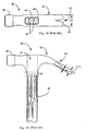
- FIG. 1A and 1B are top and side views of a conventional claw hammer, showing parts that are typical to hand-held striking devices, and parts peculiar to a conventional claw hammer. Parts common to many hand-held striking devices are an impact head 39 and a head-to-handle interface 41.
- Impact head 39 for a claw hammer typically has a substantially flat surface of sufficient size at its end for easily striking a head of a nail.
- Impact heads of many sizes and shapes are manufactured and sold to suit the peculiar use of a hand-held striking device.
- a ball-peen hammer impact head typically has one substantially flat head at one end, and a substantially rounded impact head on the other end.
- This combination provides a user with flexibility to strike a material, such as metal, a variety of ways at angles to conform the material to a desired shape.
- a pickaxe typically has two elongated impact heads that are pointed at their ends so they will penetrate dirt, rocks, or any desired surface.
- An axe commonly has one or two impact heads that have sharp wedges to allow a user to cut into wood or other materials.
- Head-to-handle interface 41 is a common configuration for many types of hand-held striking devices. It comprises interface opening 46 in hammer head 36, and retaining wedges 42. Interface opening 46 is a substantially rectangular opening of suitable size and shape to insert, and make a tight fit for, a similarly shaped hammer handle interface end 44. Retaining wedges 42 are driven into the handle interface end 44 after assembly of the head to the handle to expand handle interface end 44 so its outer surface fits tightly against the inner surface of interface opening 46. This is a conventional method for holding a hammer head to a handle.
- a conventional claw 40 having a wedge shape 62 and conventional nail-pulling slot 43.
- Conventional claw 40 is either substantially curved or only slightly curved, depending on its primary use as a nail-pulling claw or a ripping claw. In both cases, the working end of claw 40 is wedge-shaped and usually has a nail-pulling slot 43.
- the height of nail-pulling slot 43 substantially conforms to wedge thickness along its length, such as at heights D12 and D13. As will be discussed later, this characteristic limits the ability of a user to grip and pull nails when the nail heads are close to the surface of a material into which the nails are embedded.
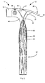
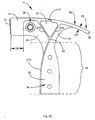
- Fig. 2 is a left side view of a claw hammer 12 according to an embodiment of the present invention.
- Claw hammer 12 comprises a claw hammer head 11 and handle 37.
- Hammer head 11 comprises an impact head 13, an optional adjustable weight assembly 35, structural webbing areas 25, 27, and 31, cross braces 29, a head-to-handle interface region 19, an optional side nail-pulling slot 17, a claw 20 having a chamfered claw end 33, and a tapered mill-pulling slot 34 (not shown, but described elsewhere).
- Claw hammer 12 has significantly greater head-to-handle interface integrity, plus versatility in weight and claw use than does the conventional claw hammer configuration already described.
- hammer heads in the prior have a nearly constant width such as width D1 in Fig. 1A.
- Hammer head 11 differs in that the several parts are distinct and connected by reinforcing webbing. This structure is shown in Fig. 3A, but will be better understood by referring to Fig. 8A, to be fully described later, then returning to Fig. 3A.
- Impact head 13 of hammer head 11 is similar to the impact head of a conventional hammer, except in hammer head 11, impact surface 15 is inclined at an angle of from 2 to 5 degrees with vertical when the long axis of the hammer handle is vertical. The inventor has found that this inclination provides for driving nails straighter than with hammers lacking such inclination. Another difference with conventional hammers is that the impact head extends from impact surface only a relatively short distance. usually about one inch or less, shown as dimension D2 in Fig. 3A.
- claw 20 in the present embodiment is a curved section with substantially constant width D3.
- An edge for ripping and tearing is formed by a chamfered end 33.
- Claw 20 in this embodiment has an optional side nail-pulling slot 17, and a tapered nail-pulling slot 34 (not shown here, but described later).
- Claw 20 in the present embodiment has greater strength and functionality for ripping and nail pulling tasks than does a conventional claw.
- impact head 13 and claw 20 are joined to a head-to-handle interface region 19 by structural reinforcing webbing regions 25 and 27 and by brace elements 21A and 21B at right angles to webbing regions 25 and 27.
- Brace elements 21 A and 21B are crossed in an integral arrangement to provide maximum strength while presenting also a pleasing and distinct visual effect.
- Fig. 4 is a right side view of hammer head 11, and shows a structure similar to that of the left side view. Reinforcing web regions 25 and 27 are in the vertical plane of symmetry of the hammer head, which again may be better seen by referring to isometric view Fig. 8A.
- Portion 31 of the hammer head, substantially triangular in shape and enclosed on three sides of the triangle by claw section 20 and reinforcing braces 21A and 21B is open through the hammer head in some embodiments.
- a web 31 similar to webs 25 and 27 is provided coplanar in the plane of symmetry with webs 25 and 27.
- web 31 is at one edge of the hammer head, opposite nail slot 17. In this manner web 31 forms an auxiliary striking surface on the side of the hammer head.
- Braces 21A and 21B cross (and are joined) at region 29 and extend in a gentle curvature in the direction handle 37 assumes in the long axis (see Fig. 2) forming and enclosed region 16 having also a central web 23.
- This region designated by a bracket and element number 19 in Fig. 3A, considering the two sides of the hammer head, forms a hammer-to-handle interface region having central web 23 and sidewalls on each side provided by braces 21A and 21B.
- interface region 19 may be best understood by reference to Fig. 8A as well as Fig. 3A and Fig. 4.
- Claw hammer head 11 as described above with reference to the Figs. is, in a preferred embodiment, forged from high carbon steel, although some other materials are also suitable. In alternative embodiments casting processes are used, and materials such as stainless steel are utilized.
- Hammer head 11 with head-to-handle interface region 19 described above is shown as a single casting or forging, can also be assembled from separate components and connected by welding, brazing, riveting, riveted, epoxy bonding, or any suitable manner without departing from the spirit and scope of the invention.
- variable head weight is provided by an adjustable weight assembly 35, which a user may change to accommodate current need.
- Fig. 5A is a front view of a claw hammer head of Fig. 4, with a portion of the impact head cut away to show adjustable weight assembly 35, which is behind impact head 13 in this view.
- Fig. 5B is a isometric view of a weight, 18 according to an embodiment of the invention. Given this unique feature, a user may adjust the weight, and therefore the inertia in operation, of the hammer head by removing and adding weights 18. Weights of different sizes are provided in some embodiments.
- braces 21A and 21B taper away in the direction of the handle interface, starting with a combined height D4 of substantially the width of the hammer bead and tapering to a width D5 of about one-fourth the width of the hammer head. This taper may be different in other embodiments.
- Adjustable weight assembly 35 comprises a conventional bolt 14, a locking nut 16, and weights 18.
- Weights 18 in are one pair of a variety weights in different sizes that may be easily removed and added.
- Weights 18 in the embodiment of Fig. 5A are cylindrical, but-may be of any convenient shape without departing from the intent of the present invention. Although the weights are held in place by a bolt and locking nut in the embodiment shown, in other embodiments the weights may be fastened to the hammer head in a variety of ways. It is deemed important by the inventor that the weights be held securely, to avoid being jarred loose by virtue of the rather severe impacts experienced in use.
- Fig. 5C is a view of just the face of impact head 39 in the same direction as Fig. 5A.
- This shape may vary in other embodiments, but has a semicircular lower aspect and an upper aspect with rounded comers. This shape allows a user to use the hammer in comers better than if the face were entirely circular.
- Fig. 6 is a rear view of hammer head 11 of Figs. 3A, 4, and 5A, showing claw 20, nail slot 34, and chamfered end 33 from this vantage.
- Chamfered claw end 33 provides a sharp edge required for ripping tasks. Providing the ripping edge as a chamfer also allows claw 20 to be fashioned in substantially uniform thickness as described with reference to Fig. 3A. This provides improved strength over conventional claw hammers, which is an advantage for nail pulling and ripping tasks.
- Fig. 7 is a top view of hammer head 11, showing connectivity of web 25, web 27, braces 21A and 21B, and center web 31.
- the structure may be of a single piece, as with a forging or a casting, or may be fabricated by welding from separate parts.
- Center web 31 is aligned in the embodiment shown flush with one side of the hammer head.
- this wall structure may be centrally located, as with webs 25 and 27. The location of this web, if used, should not block side nail-pulling slot 17.
- the head may be open through this area with no web 31. The placement of web 31 to the far side of the head from side nail-pulling slot provides a side striking surface for the hammer, which is convenient in many situations.
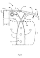
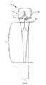
- Fig. 8A is an exploded isometric view of hammer head 11 and a two-piece handle 37 comprising parts 49A and 49B in an embodiment of the present invention.
- Handle 49A has a recessed area 28 with a height D6 and length D7. Height D6 and length D7 substantially correspond to thickness D5 and length D7 of interface web 23. The purpose of this recessed area is to accommodate web 23 in assembly while allowing the two portions of the handle to come together.
- the recess can be in either handle portion, and in some embodiments the recess may be in both handle portions, each with a depth of one-half the thickness of web 23.
- Each of handle parts 49A and 49B has a nose region 48 shaped to fit a matching socket provided on each side of head-to-handle interface region 19 of hammer head 11.
- This shape includes, on each part, surfaces 50 to match the inside surfaces 50a formed by brace elements 21A and 21B on each side of the head-to-handle interface.
- Handle parts 49A and 49B come together in the sockets on each side of the head-to-handle interface and are joined by fasteners 30 (see Fig. 2).
- fasteners 30 In embodiments utilizing such fasteners, opening through web 23 are provided, even though these openings are not shown in Fig. 8A.
- the fasteners can be any of a number of conventional types, such as rivets or screw thread fasteners with large decorative heads.
- an adhesive filler may be used to assure a secure bond in joining the two handle parts to the hammer head.
- bending moments are produced in planes parallel to the major axis of symmetry of the hammer as the hammer is used, either in impacting a nail or a surface with impact head 13 or in nail pulling or ripping operations with claw 20.
- a conventional hammer Fig. 1B
- these moments are concentrated in a small area 48.
- these effects are spread over a the entire handle area in interface region 19, and absorbed by the inner surfaces of brace elements 21A and 21B along the length of region 19. Stress and strain are therefore very much less, and the hammer assembly may be expected to be much more reliable and durable than has been available in the prior art.
- the force applied to the hammer handle in pulling nails and in use of striking surface 31 is at right angles to the force applied in striking with impact head 13 and in nail pulling and ripping with claw 20 and nail-pulling slot 34. Bending moments produced in these operations are then at right angles to those produced in impacting with head 13 and in nail pulling and ripping with claw 20 (slot 34).
- the forces in this case are spread over the surface areas of web 23, and the stresses and strains produced are much lower than in the conventional case.
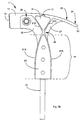
- Fig. 8B is another exploded view of claw hammer head 11 and a handle according to another embodiment of the present invention.
- the handle is a single piece having a slot 38 of height D9 and length D10, which corresponds dimensionally to height D5 and length D7 of interface region 19.
- Handle 37a in assembly simply slides into place, filling the sockets created by web 23 and sidewalls of brace elements 21A and 21B, and is fastened by the expedients described above for the two-piece handle with reference to Fig. 8A.
- a center spine 22 is provided, welded or otherwise fastened to web 23 to provide a high-strength inner axis for a handle.
- appropriate grooves may be provided in wooden handle parts to accommodate the inner spine, or a handle may be molded-in-place, still filling the interface region 19, which, even in this case, provides additional strength and durability.
- the unique head-to-handle interface has been described by the example of a claw hammer.
- a claw hammer is not the only tool which might well benefit from such an interface.
- the interface is applicable to nearly all sorts of striking and pulling tools.
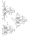
- FIG. 9A is an elevation view of a sledge hammer head 60 with a head-to-handle interface 55 according to an embodiment of the present invention.
- sledge hammer head 60 corresponds to the construction of hammer head 11 described in detail above, including head-to-handle interface 55 corresponding to head-to-handle interface 19 described above.
- variable weight assemblies 53A and 53B corresponding to variable weight assembly 35 in the hammer embodiment. This feature is optional.
- Fig. 9B shows a pickaxe head 70 with head-to-handle interface 73 according to an embodiment the present invention.
- Pickaxe head 70 has impact heads 63A and 63B, variable weight assemblies 65A and 65B, a center web 64 (optional), a front web 67, a rear web 69, interface web 66, and brace elements 68A and 68B.
- Impact heads 63A and 63B have a substantially pointed or bladed surface to suit traditional uses of a pickaxe.
- FIG. 9C shows an axe head 80 with a head-to-handle interface 89.
- Axe head 80 has impact heads 75A and 75B, variable weight assemblies 77A and 77B, a center web 76 (optional), front web 81, rear web 85, interface web 83, and brace elements 91A and 91B.
- Impact heads 75A and 75B have a wedges cutting edges to suit traditional uses of an axe.
- Figs. 10A, 10B, and 10C are top, left elevation, and enlarged rear views of a conventional claw hammer, showing a claw and nail pulling slot according to conventional art.
- Fig. 11A, 11B, and 11C are top, left elevation, and enlarged rear views of a claw hammer in an embodiment of the present invention, showing a claw and nail pulling slot according to the present invention.
- Conventional claw 40 (Fig. 10A, 10B, and 10C) is either substantially curved or only slightly curved, depending on intention as a nail-pulling claw or a ripping claw.
- the working end of claw 40 is wedge-shaped and has a nail slot 43 (Fig. 10C) whose height conforms to the thickness of wedge region 43 in Fig. 1B, which may vary from a height of D12 to D13 along the wedge length D14 (Fig. 10A).
- the sidewalls of the nail-pulling slot are vertical, so, when pulling nails, the underside of the nail head is held against opposite surface 52. Because of this, a nail with its head very close to a surface wherein the nail is embedded cannot be fully engaged and pulled with a single stroke.
- Figs. 11A, 11B and 11C show a top view, a side elevation view, and a rear elevation view of hammer head I 1 having claw 20 and nail-pulling slot 34.
- slot 34 has angled sidewalls such that the width of the slot at the undersurface of the claw is substantially greater than at the top surface, as seen in Fig. 11C. That is, dimension D15 is substantially greater than dimension D16.
- This taper is such that most conventional nail heads are held within slot 34 rather than against a surface of the claw.
- the included angle is equal to or greater than forty degrees.
- Claw 20 is substantially straighter than the curved claw of a conventional nail-pulling claw hammer and more closely resembles the curvature of a conventional ripping claw.
- Claw 20 also has a substantially constant thickness D3 (Fig. 11B, 11C, and Fig. 3A)).
- a sharp edge for ripping tasks is provided by chamfered claw end 33.
- brace elements shown as 21A and 21B in Fig. 3A do not provide sidewalls all around the periphery of web 23, but only on one edge of web 23.
- Fig. 3C is a side elevation view of a hammer head and a head-to-handle interface according to this embodiment.
- brace element 21A extends the full length of web 23, and forms side walls orthogonal to web 23 on opposite sides of web 23, but web 21B extends only to web 21A, and does not form a sidewall to web 23.
- web 23 and web 27 are contiguous.
- sidewalls are not really necessary on both edges of web 23 in the head-to-handle interface, and as long as a handle is securely joined to the web and abutts the one sidewall, sufficient strength is imparted for striking and other tasks to be performed by a tool having the interface.
- handles may be fastened to heads of striking tools in embodiments of the invention.
- fasteners and adhesive fastening are described above.
- Handles may be of wood in a preferred embodiment, and many professionals still prefer wooden handles.
- Other materials may be used, however, such as molded polymer materials.
- variable weights may be provided and held in place other than the specific embodiments described. The invention is limited only by the language of the claims which follow.
Description
Claims (14)
- A striking tool head portion (11) for a striking tool (12), the head portion including an impact head (13) and a head-to-handle interface for attaching a handle (37) to extend in a first direction, the interface comprising:a central plate (23) having a longitudinal axis extending in the first direction; andsidewalls (21A) substantially orthogonal to the central plate (23) extending along at least one edge of the central plate (23) other than the edge presented in the first direction, forming sockets on each side of the central plate for accepting a handle (37).
- A head portion (11) as claimed in claim 1 further comprising a reinforcing rail (22) joined to the central plate (23) and extending in the first direction, forming a reinforcement for a handle (37) to be added.
- A head portion (11) as claimed in claim 1 or claim 2 and further comprising a variable weight apparatus (35) positioned adjacent the impact head (13), the variable weight apparatus comprising removable weights (18) and an attachment apparatus (14, 16) for holding the weights securely to the head (11).
- A head portion as claimed in any one preceding claim wherein sidewalls (21A) extend substantially orthogonal to the central plate (23) extending on each side of the central plate (23) around the periphery of the central plate other than the edge presented in the first direction, forming sockets on each side of the central plate for accepting a handle (37).
- A head portion (11) for a striking tool (12) as claimed in any one preceding claim, wherein the striking tool is a claw hammer having an impact head (13) and a claw (20)
- A head portion as claimed in claim 5, wherein the head portion has a central plane of symmetry, the impact head (13) and a claw (20) are joined by webbing elements (25, 27, 31) lying in the central plane of symmetry, and wherein the central plate (23) is coplanar with the webbing elements.
- A head portion (11) for a striking tool as claimed in any one of claims I to 4, wherein the striking tool is one of a pickaxe, a sledgehammer, a maul, or an axe.
- A striking tool (12) comprising a head portion (11) according to any one preceding claim.
- A striking tool (12) as claimed in claim 8 and including a handle (37) engaged in the head-to-handle interface, wherein the handle is adapted to fit into the sockets formed by the central plate (23) and the sidewalls (21 A).
- A striking tool (12) as claimed in claim 8 or 9, wherein the handle is a two-piece handle (37), the two pieces joined to one another enclosing and joining to the central plate (23).
- A striking tool as claimed in claim 8 or 9, wherein the handle (37) is a one-piece handle having a slot (38) at one end adapted to enclose the central plate (23).
- A claw hammer including a head portion as claimed in any one of claims 1 to 6 and having a central plane of symmetry, the impact head (13) being centered on the plane of symmetry and having a length L1 in the plane of symmetry and a width W1 at right angles to the plane of symmetry; and comprising:wherein the nail-pulling slot (34) has internal walls tapered away from the outer surface of the claw, the included angle made by the tapered walls equal to or greater than 40 degrees.a curved claw (20) extending a length L2 from the impact head (13), having width W2 substantially equal to W1, a substantially constant thickness T1 along the curved length, and an outer surface to the outside of the curve of the claw (20); anda nail-pulling slot (34) at the end of the claw (20) opposite the impact head (13);
- A claw hammer as claimed in claim 12 wherein the impact head (13) and the claw (20) are connected by webs (25, 27, 31) in the plane of symmetry, and reinforcement is added by bracing wall elements (21A, 21B) of substantially the thickness of the webs extending substantially at right angles to the webs on both sides of the centrally located webs, not exceeding in overall height width W1.
- A claw hammer as claimed in claim 13, wherein an interface web (23) in the plane of symmetry extends away from the impact head (13) and claw (20) in the direction of a handle (37) of the claw hammer, and wherein the brace elements (21A, 21B) extend away from the impact head (13) and the claw (20) forming walls around the interface web (25, 27) on both sides of the interface web, except in the direction of the handle, the interface web (23) and the brace elements (21A, 21B) forming thereby sockets on each side of the interface web adapted for receiving the handle.
Applications Claiming Priority (3)
| Application Number | Priority Date | Filing Date | Title |
|---|---|---|---|
| US624178 | 1990-12-07 | ||
| US08/624,178 US5768956A (en) | 1996-03-28 | 1996-03-28 | Striking tool |
| PCT/US1997/005158 WO1997035689A1 (en) | 1996-03-28 | 1997-03-28 | An improved striking tool |
Publications (3)
| Publication Number | Publication Date |
|---|---|
| EP0932478A1 EP0932478A1 (en) | 1999-08-04 |
| EP0932478A4 EP0932478A4 (en) | 2000-09-27 |
| EP0932478B1 true EP0932478B1 (en) | 2004-10-13 |
Family
ID=24500992
Family Applications (1)
| Application Number | Title | Priority Date | Filing Date |
|---|---|---|---|
| EP97917707A Expired - Lifetime EP0932478B1 (en) | 1996-03-28 | 1997-03-28 | An improved striking tool |
Country Status (7)
| Country | Link |
|---|---|
| US (7) | US5768956A (en) |
| EP (1) | EP0932478B1 (en) |
| JP (1) | JP3404048B2 (en) |
| AU (1) | AU720459B2 (en) |
| CA (1) | CA2272914C (en) |
| DE (1) | DE69731214T2 (en) |
| WO (1) | WO1997035689A1 (en) |
Cited By (1)
| Publication number | Priority date | Publication date | Assignee | Title |
|---|---|---|---|---|
| TWI727611B (en) * | 2020-01-16 | 2021-05-11 | 唐州工業股份有限公司 | Pry tool |
Families Citing this family (61)
| Publication number | Priority date | Publication date | Assignee | Title |
|---|---|---|---|---|
| US5768956A (en) | 1996-03-28 | 1998-06-23 | Coonrad; Todd Douglas | Striking tool |
| US5952916A (en) * | 1998-05-28 | 1999-09-14 | Atras Auto Co., Ltd | Hammer-equipped emergency signal device |
| USD425772S (en) * | 1998-11-12 | 2000-05-30 | Emerson Electric Co. | Claw hammer head |
| USD432380S (en) * | 1999-11-09 | 2000-10-24 | Fred Goble | Hammer head |
| US6666566B1 (en) | 1999-11-12 | 2003-12-23 | Underwater Kinetics | Emergency device with glass breaking function |
| US6494119B1 (en) * | 2000-04-06 | 2002-12-17 | Douglas Tool, Inc. | Strongback system for joining a handle to a hammer head |
| US6837613B2 (en) * | 2001-04-10 | 2005-01-04 | Levtech, Inc. | Sterile fluid pumping or mixing system and related method |
| DE10100405C2 (en) * | 2001-01-05 | 2002-11-21 | Joh Hermann Picard Gmbh & Co | Hand tool for processing stones and stone-like materials |
| US6604728B1 (en) * | 2001-06-14 | 2003-08-12 | Kevin Boydon | Multiple use hammer |
| US6715734B1 (en) * | 2001-10-05 | 2004-04-06 | Robert W. Wise | Cabinet and mill work finish bar |
| GB2383771A (en) * | 2002-01-04 | 2003-07-09 | Keith England | Percussive Hand Tools |
| GB2384741A (en) * | 2002-02-02 | 2003-08-06 | Keith England | Hammers and the like |
| US6701805B2 (en) | 2002-03-15 | 2004-03-09 | Richard B. Souder | Stone working tool having multiple striking edges on reversible-replaceable plates |
| WO2004014615A1 (en) * | 2002-08-07 | 2004-02-19 | Estwing Manufacturing Company | Striking tool with weight forward head |
| US8109178B2 (en) * | 2003-01-21 | 2012-02-07 | Santa Ana Roland C | Side-load nail holding hammer |
| US6901822B2 (en) * | 2003-07-29 | 2005-06-07 | Soundstarts, Inc. | Method and apparatus for joining a handle to a hammer head |
| FR2870473B1 (en) * | 2004-05-18 | 2007-08-03 | Participations Sa G | HAND TOOL OF HAMMER TYPE |
| US6923432B1 (en) | 2004-07-26 | 2005-08-02 | Mark Martinez | Side nail puller |
| US20060021474A1 (en) * | 2004-07-28 | 2006-02-02 | Michael Burgess | Double headed striking tool |
| US7066052B2 (en) * | 2004-10-01 | 2006-06-27 | John Chen | Hammer having enhanced strength |
| FR2888264B1 (en) * | 2005-07-11 | 2011-02-25 | Mob Outil | HAMMER COFFREUR |
| US8117702B2 (en) * | 2006-03-29 | 2012-02-21 | Stanley Black & Decker, Inc. | Demolition tool |
| JP2008000447A (en) * | 2006-06-23 | 2008-01-10 | Kenzo Kase | Body hammer |
| US20080087443A1 (en) * | 2006-09-13 | 2008-04-17 | Christina Jemail | Hoof pick |
| US20080066582A1 (en) * | 2006-09-20 | 2008-03-20 | Yung-Shou Chen | Hammer structure |
| US20080156844A1 (en) * | 2007-01-03 | 2008-07-03 | Austin Raymond Savio Braganza | Staple gun |
| US8833207B2 (en) | 2007-01-30 | 2014-09-16 | Pull'r Holding Company, Llc | Graphite/titanium hammer with wooden handle |
| US8024994B2 (en) * | 2007-06-26 | 2011-09-27 | Stanley Black & Decker, Inc. | Demolition utility tool |
| US8141458B1 (en) * | 2008-11-13 | 2012-03-27 | Spencer Stephen M | Hammer head with recessed traction striking surface |
| US8047099B2 (en) | 2009-02-09 | 2011-11-01 | Stanley Black & Decker, Inc. | Large strike face hammer |
| US9808946B2 (en) | 2009-07-21 | 2017-11-07 | Dana Stone Clarke | Apparatus for splitting wood into kindling |
| US20110120270A1 (en) * | 2009-11-23 | 2011-05-26 | Stanley Black & Decker, Inc. | Welded hammer |
| US8794597B1 (en) * | 2010-09-03 | 2014-08-05 | 5.11 Inc. | Breaching tools for entry of doors and windows |
| US20130126807A1 (en) | 2011-11-22 | 2013-05-23 | Stanley Black & Decker, Inc. | Welded hammer |
| CN102773844A (en) * | 2012-08-10 | 2012-11-14 | 山东金釜工具股份有限公司 | Multifunctional fire crowbar |
| US9204625B2 (en) | 2012-08-17 | 2015-12-08 | S.C. Johnson & Son, Inc. | Dispenser |
| US8894044B2 (en) | 2012-08-17 | 2014-11-25 | S.C. Johnson & Son, Inc. | Dispenser |
| US9649400B2 (en) | 2012-08-17 | 2017-05-16 | S.C. Johnson & Son, Inc. | Method and system for dispensing a composition |
| USD804271S1 (en) | 2013-01-06 | 2017-12-05 | Lowe's Companies, Inc. | Hammer |
| USD764886S1 (en) | 2013-03-15 | 2016-08-30 | Dana Stone Clarke | Axe for splitting wood into kindling or the like |
| USD704813S1 (en) | 2013-06-17 | 2014-05-13 | S. C. Johnson & Son, Inc. | Dispenser |
| US9193059B2 (en) * | 2013-09-12 | 2015-11-24 | Stanley Black & Decker, Inc. | Hammer with bend resistant handle |
| US9358674B2 (en) * | 2013-09-17 | 2016-06-07 | Richard John Lasaga | Hand tool for removing nails |
| DE102013016176A1 (en) * | 2013-09-30 | 2015-04-02 | Helmut Obieglo | impactors |
| CA156201S (en) | 2013-10-21 | 2015-01-12 | Lowes Co Inc | Hammer |
| US10046454B2 (en) | 2014-01-29 | 2018-08-14 | Klecker Knives, LLC | Tool head adapted for removable attachment to a handle |
| GB2541304B (en) | 2014-03-07 | 2020-12-02 | Estwing Mfg Company | Striking tool with attached striking surface |
| CA2943529C (en) * | 2014-03-07 | 2019-02-05 | Estwing Manufacturing Company, Inc. | Aluminum striking tools |
| USD752938S1 (en) | 2014-03-14 | 2016-04-05 | Estwing Manufacturing Company, Inc. | Hammer |
| US10377556B2 (en) | 2015-02-04 | 2019-08-13 | S.C. Johnson & Son, Inc. | Retaining apparatus |
| USD795668S1 (en) | 2016-05-13 | 2017-08-29 | Gregory Poulos | Breaching tool |
| USD829074S1 (en) | 2016-09-21 | 2018-09-25 | Estwing Manufacturing Company, Inc. | Hammer |
| USD834909S1 (en) | 2017-05-15 | 2018-12-04 | Greg Poulos LLC | Breaching tool |
| US10518189B2 (en) | 2017-09-20 | 2019-12-31 | Mattel-Mega Holdings (Us), Llc | Tool for use with toy construction elements |
| USD860334S1 (en) | 2017-09-20 | 2019-09-17 | Mattel-Mega Holdings (Us), Llc | Construction set tool |
| US10564229B2 (en) | 2017-10-16 | 2020-02-18 | Tdk Corporation | Tunnel magnetoresistive effect element, magnetic memory, and built-in memory |
| US11052523B1 (en) * | 2019-06-13 | 2021-07-06 | Paul Janson | Framing hammer |
| USD947641S1 (en) | 2019-10-11 | 2022-04-05 | Southwire Company, Llc | Hammer |
| US20210323133A1 (en) * | 2020-04-21 | 2021-10-21 | Apex Brands, Inc. | Hammer With Handle Balance |
| US11214188B1 (en) | 2020-04-27 | 2022-01-04 | Don Ferris | Dekhand |
| US20230311287A1 (en) * | 2020-10-23 | 2023-10-05 | Vanderbilt University | Multifunctional hammer |
Family Cites Families (27)
| Publication number | Priority date | Publication date | Assignee | Title |
|---|---|---|---|---|
| US378650A (en) * | 1888-02-28 | Nail-hammer | ||
| US845672A (en) * | 1906-03-14 | 1907-02-26 | John A Thompson | Nail-extractor. |
| US835961A (en) * | 1906-03-31 | 1906-11-13 | John W Key | Wire-stretcher. |
| US949337A (en) * | 1907-09-30 | 1910-02-15 | Emery Bruley | Nail or spike puller. |
| US967703A (en) * | 1908-10-30 | 1910-08-16 | Sidney T Bagnall | Implement-handle fastening. |
| US1508874A (en) * | 1921-11-29 | 1924-09-16 | Christensen Hans | Hammer and handle assembly |
| US1869129A (en) * | 1925-02-04 | 1932-07-26 | Robert S Blair | Claw hammer |
| US2330092A (en) * | 1942-01-12 | 1943-09-21 | Armand A Vanasse | Combination tool |
| FR937788A (en) * | 1945-11-26 | 1948-08-26 | Improvements to hammers, axes and similar tools | |
| US2863635A (en) * | 1956-06-08 | 1958-12-09 | Fred B Fandrich | Sure grip combination bar |
| GB1291845A (en) * | 1969-06-09 | 1972-10-04 | Spear & Jackson Ltd | An improvement in or relating to hammers |
| FR2274407A1 (en) * | 1974-06-14 | 1976-01-09 | Loire Milourd Ets Moulin Blanc | Hammer head securing system - synthetic resin handle moulded into recessed anchorage zone |
| US4367969A (en) * | 1979-08-31 | 1983-01-11 | Carmien Joseph A | Bushing for attaching fiberglass tool handles |
| US4558726A (en) * | 1981-04-27 | 1985-12-17 | Clay Howard W | Hammer with replaceable head |
| USD275261S (en) * | 1981-11-27 | 1984-08-28 | Crowder Thomas E | Hammer |
| US4773286A (en) * | 1986-01-27 | 1988-09-27 | Krauth Walter K | Striking tool, head and handle and methods of manufacturing them |
| GB8619165D0 (en) * | 1986-08-06 | 1986-09-17 | Thor Hammer Co Ltd | Split head hammers |
| US4831901A (en) * | 1987-04-29 | 1989-05-23 | Kinne Arnold L | Carpenters hammer double jolt |
| US4890518A (en) * | 1989-06-12 | 1990-01-02 | Floyd Ted J | Hammer |
| US5211085A (en) * | 1992-03-31 | 1993-05-18 | Liou Mou T | Hammer |
| US5216939A (en) * | 1992-10-02 | 1993-06-08 | Swenson William B | Interchangeable tip and/or weight hammer |
| DE4331660A1 (en) * | 1993-09-17 | 1995-03-23 | Halder Erwin Kg | Soft-face hammer |
| USD353758S (en) * | 1993-12-06 | 1994-12-27 | Frykman John B | Hammerhead |
| US5768956A (en) * | 1996-03-28 | 1998-06-23 | Coonrad; Todd Douglas | Striking tool |
| USD410184S (en) * | 1998-05-06 | 1999-05-25 | Bruce Jefferson Bulcock | Hammer with accessories |
| USD426128S (en) * | 1999-05-05 | 2000-06-06 | General Housewares Corporation | Hammer |
| USD432380S (en) * | 1999-11-09 | 2000-10-24 | Fred Goble | Hammer head |
-
1996
- 1996-03-28 US US08/624,178 patent/US5768956A/en not_active Expired - Lifetime
-
1997
- 1997-03-28 AU AU25964/97A patent/AU720459B2/en not_active Ceased
- 1997-03-28 JP JP53465997A patent/JP3404048B2/en not_active Expired - Fee Related
- 1997-03-28 CA CA002272914A patent/CA2272914C/en not_active Expired - Fee Related
- 1997-03-28 WO PCT/US1997/005158 patent/WO1997035689A1/en active IP Right Grant
- 1997-03-28 DE DE69731214T patent/DE69731214T2/en not_active Expired - Fee Related
- 1997-03-28 EP EP97917707A patent/EP0932478B1/en not_active Expired - Lifetime
-
1998
- 1998-04-21 US US09/064,205 patent/US5860334A/en not_active Expired - Fee Related
-
1999
- 1999-01-19 US US09/234,042 patent/US5988019A/en not_active Expired - Fee Related
- 1999-11-04 US US09/435,318 patent/US6131488A/en not_active Expired - Fee Related
-
2000
- 2000-08-07 US US09/633,553 patent/US6250181B1/en not_active Expired - Fee Related
-
2001
- 2001-03-20 US US09/814,021 patent/US6460430B2/en not_active Expired - Fee Related
-
2002
- 2002-10-07 US US10/266,818 patent/US6615691B2/en not_active Expired - Fee Related
Cited By (1)
| Publication number | Priority date | Publication date | Assignee | Title |
|---|---|---|---|---|
| TWI727611B (en) * | 2020-01-16 | 2021-05-11 | 唐州工業股份有限公司 | Pry tool |
Also Published As
| Publication number | Publication date |
|---|---|
| CA2272914A1 (en) | 1997-10-02 |
| EP0932478A4 (en) | 2000-09-27 |
| CA2272914C (en) | 2004-06-22 |
| AU2596497A (en) | 1997-10-17 |
| US6250181B1 (en) | 2001-06-26 |
| JP3404048B2 (en) | 2003-05-06 |
| WO1997035689A1 (en) | 1997-10-02 |
| AU720459B2 (en) | 2000-06-01 |
| US6460430B2 (en) | 2002-10-08 |
| EP0932478A1 (en) | 1999-08-04 |
| US5768956A (en) | 1998-06-23 |
| US5988019A (en) | 1999-11-23 |
| US20030037641A1 (en) | 2003-02-27 |
| US6615691B2 (en) | 2003-09-09 |
| DE69731214T2 (en) | 2005-10-13 |
| US5860334A (en) | 1999-01-19 |
| US20010010182A1 (en) | 2001-08-02 |
| US6131488A (en) | 2000-10-17 |
| DE69731214D1 (en) | 2004-11-18 |
| JP2001526592A (en) | 2001-12-18 |
Similar Documents
| Publication | Publication Date | Title |
|---|---|---|
| EP0932478B1 (en) | An improved striking tool | |
| US8585016B2 (en) | Demolition tool | |
| US5820107A (en) | Multi-use lever | |
| US6961985B2 (en) | Method and apparatus for joining a handle to a hammer head | |
| US6113074A (en) | Multi-purpose construction tool | |
| CA2381762C (en) | A light-weight striking tool | |
| CA2513838A1 (en) | Striking or pulling tool with a split head | |
| CA1291473C (en) | Lumber turning tool with leverage enhancing claw surfaces | |
| US6058809A (en) | Family of dismantling devices | |
| US6799359B2 (en) | Strongback system for joining a handle to a hammer head | |
| US5906144A (en) | Toe-nailing hammer | |
| US20060021474A1 (en) | Double headed striking tool | |
| US20040149086A1 (en) | Attachment for a tool | |
| JPH0723170Y2 (en) | Mallet | |
| CA2280368A1 (en) | Combination construction tool | |
| Nagyszlanczy | The Homeowner's Ultimate Tool Guide | |
| KR20070046055A (en) | A blow strengtheninghammer and ax | |
| CA2475581A1 (en) | Double headed striking tool | |
| AU2478301A (en) | Improvements in and relating to a hand tool |
Legal Events
| Date | Code | Title | Description |
|---|---|---|---|
| PUAI | Public reference made under article 153(3) epc to a published international application that has entered the european phase |
Free format text: ORIGINAL CODE: 0009012 |
|
| 17P | Request for examination filed |
Effective date: 19981006 |
|
| AK | Designated contracting states |
Kind code of ref document: A1 Designated state(s): DE FR GB IE |
|
| A4 | Supplementary search report drawn up and despatched |
Effective date: 20000817 |
|
| AK | Designated contracting states |
Kind code of ref document: A4 Designated state(s): DE FR GB IE |
|
| RIC1 | Information provided on ipc code assigned before grant |
Free format text: 7B 25D 1/00 A, 7B 25C 11/00 B, 7B 25G 3/36 B |
|
| 17Q | First examination report despatched |
Effective date: 20011004 |
|
| GRAP | Despatch of communication of intention to grant a patent |
Free format text: ORIGINAL CODE: EPIDOSNIGR1 |
|
| GRAS | Grant fee paid |
Free format text: ORIGINAL CODE: EPIDOSNIGR3 |
|
| GRAA | (expected) grant |
Free format text: ORIGINAL CODE: 0009210 |
|
| AK | Designated contracting states |
Kind code of ref document: B1 Designated state(s): DE FR GB IE |
|
| REG | Reference to a national code |
Ref country code: GB Ref legal event code: FG4D |
|
| REG | Reference to a national code |
Ref country code: IE Ref legal event code: FG4D |
|
| REF | Corresponds to: |
Ref document number: 69731214 Country of ref document: DE Date of ref document: 20041118 Kind code of ref document: P |
|
| PG25 | Lapsed in a contracting state [announced via postgrant information from national office to epo] |
Ref country code: IE Free format text: LAPSE BECAUSE OF NON-PAYMENT OF DUE FEES Effective date: 20050328 Ref country code: GB Free format text: LAPSE BECAUSE OF NON-PAYMENT OF DUE FEES Effective date: 20050328 |
|
| PLBE | No opposition filed within time limit |
Free format text: ORIGINAL CODE: 0009261 |
|
| STAA | Information on the status of an ep patent application or granted ep patent |
Free format text: STATUS: NO OPPOSITION FILED WITHIN TIME LIMIT |
|
| PG25 | Lapsed in a contracting state [announced via postgrant information from national office to epo] |
Ref country code: DE Free format text: LAPSE BECAUSE OF NON-PAYMENT OF DUE FEES Effective date: 20051001 |
|
| 26N | No opposition filed |
Effective date: 20050714 |
|
| ET | Fr: translation filed | ||
| GBPC | Gb: european patent ceased through non-payment of renewal fee |
Effective date: 20050328 |
|
| REG | Reference to a national code |
Ref country code: IE Ref legal event code: MM4A |
|
| REG | Reference to a national code |
Ref country code: FR Ref legal event code: ST Effective date: 20080229 |
|
| PG25 | Lapsed in a contracting state [announced via postgrant information from national office to epo] |
Ref country code: FR Free format text: LAPSE BECAUSE OF NON-PAYMENT OF DUE FEES Effective date: 20050331 |