EP0932141B1 - Method for signal controlled switching between different audio coding schemes - Google Patents
Method for signal controlled switching between different audio coding schemes Download PDFInfo
- Publication number
- EP0932141B1 EP0932141B1 EP99100790A EP99100790A EP0932141B1 EP 0932141 B1 EP0932141 B1 EP 0932141B1 EP 99100790 A EP99100790 A EP 99100790A EP 99100790 A EP99100790 A EP 99100790A EP 0932141 B1 EP0932141 B1 EP 0932141B1
- Authority
- EP
- European Patent Office
- Prior art keywords
- speech
- transform
- coding
- time domain
- signals
- Prior art date
- Legal status (The legal status is an assumption and is not a legal conclusion. Google has not performed a legal analysis and makes no representation as to the accuracy of the status listed.)
- Expired - Lifetime
Links
- 238000000034 method Methods 0.000 title claims abstract description 56
- 230000005236 sound signal Effects 0.000 claims abstract description 40
- 230000007704 transition Effects 0.000 claims description 18
- 238000005070 sampling Methods 0.000 claims description 8
- 230000005540 biological transmission Effects 0.000 claims description 4
- 238000012805 post-processing Methods 0.000 claims description 4
- 230000015556 catabolic process Effects 0.000 claims description 3
- 238000006731 degradation reaction Methods 0.000 claims description 3
- 238000012545 processing Methods 0.000 claims 2
- 238000004458 analytical method Methods 0.000 description 16
- 230000005284 excitation Effects 0.000 description 16
- 238000001228 spectrum Methods 0.000 description 14
- 230000015572 biosynthetic process Effects 0.000 description 11
- 238000003786 synthesis reaction Methods 0.000 description 11
- 238000013139 quantization Methods 0.000 description 10
- 230000003044 adaptive effect Effects 0.000 description 8
- 238000010586 diagram Methods 0.000 description 8
- 230000006870 function Effects 0.000 description 8
- 230000008569 process Effects 0.000 description 8
- 238000013213 extrapolation Methods 0.000 description 7
- 238000012856 packing Methods 0.000 description 7
- 230000000873 masking effect Effects 0.000 description 6
- 238000012546 transfer Methods 0.000 description 5
- 230000008901 benefit Effects 0.000 description 4
- 230000003247 decreasing effect Effects 0.000 description 4
- 238000013459 approach Methods 0.000 description 3
- 230000001419 dependent effect Effects 0.000 description 3
- 238000011002 quantification Methods 0.000 description 3
- 238000010998 test method Methods 0.000 description 3
- 238000004364 calculation method Methods 0.000 description 2
- 230000008859 change Effects 0.000 description 2
- 238000004891 communication Methods 0.000 description 2
- 230000003111 delayed effect Effects 0.000 description 2
- 238000001514 detection method Methods 0.000 description 2
- 230000004044 response Effects 0.000 description 2
- 239000006227 byproduct Substances 0.000 description 1
- 230000000694 effects Effects 0.000 description 1
- 238000005516 engineering process Methods 0.000 description 1
- 238000001914 filtration Methods 0.000 description 1
- 238000013100 final test Methods 0.000 description 1
- 238000009499 grossing Methods 0.000 description 1
- 230000006872 improvement Effects 0.000 description 1
- 230000007246 mechanism Effects 0.000 description 1
- 230000004048 modification Effects 0.000 description 1
- 238000012986 modification Methods 0.000 description 1
- 239000000047 product Substances 0.000 description 1
- 230000009467 reduction Effects 0.000 description 1
- 238000011946 reduction process Methods 0.000 description 1
- 230000003595 spectral effect Effects 0.000 description 1
- 230000002194 synthesizing effect Effects 0.000 description 1
Images



Classifications
-
- G—PHYSICS
- G10—MUSICAL INSTRUMENTS; ACOUSTICS
- G10L—SPEECH ANALYSIS TECHNIQUES OR SPEECH SYNTHESIS; SPEECH RECOGNITION; SPEECH OR VOICE PROCESSING TECHNIQUES; SPEECH OR AUDIO CODING OR DECODING
- G10L19/00—Speech or audio signals analysis-synthesis techniques for redundancy reduction, e.g. in vocoders; Coding or decoding of speech or audio signals, using source filter models or psychoacoustic analysis
- G10L19/04—Speech or audio signals analysis-synthesis techniques for redundancy reduction, e.g. in vocoders; Coding or decoding of speech or audio signals, using source filter models or psychoacoustic analysis using predictive techniques
- G10L19/16—Vocoder architecture
- G10L19/18—Vocoders using multiple modes
- G10L19/20—Vocoders using multiple modes using sound class specific coding, hybrid encoders or object based coding
-
- G—PHYSICS
- G10—MUSICAL INSTRUMENTS; ACOUSTICS
- G10L—SPEECH ANALYSIS TECHNIQUES OR SPEECH SYNTHESIS; SPEECH RECOGNITION; SPEECH OR VOICE PROCESSING TECHNIQUES; SPEECH OR AUDIO CODING OR DECODING
- G10L19/00—Speech or audio signals analysis-synthesis techniques for redundancy reduction, e.g. in vocoders; Coding or decoding of speech or audio signals, using source filter models or psychoacoustic analysis
- G10L19/005—Correction of errors induced by the transmission channel, if related to the coding algorithm
-
- G—PHYSICS
- G10—MUSICAL INSTRUMENTS; ACOUSTICS
- G10L—SPEECH ANALYSIS TECHNIQUES OR SPEECH SYNTHESIS; SPEECH RECOGNITION; SPEECH OR VOICE PROCESSING TECHNIQUES; SPEECH OR AUDIO CODING OR DECODING
- G10L19/00—Speech or audio signals analysis-synthesis techniques for redundancy reduction, e.g. in vocoders; Coding or decoding of speech or audio signals, using source filter models or psychoacoustic analysis
- G10L19/02—Speech or audio signals analysis-synthesis techniques for redundancy reduction, e.g. in vocoders; Coding or decoding of speech or audio signals, using source filter models or psychoacoustic analysis using spectral analysis, e.g. transform vocoders or subband vocoders
- G10L19/0212—Speech or audio signals analysis-synthesis techniques for redundancy reduction, e.g. in vocoders; Coding or decoding of speech or audio signals, using source filter models or psychoacoustic analysis using spectral analysis, e.g. transform vocoders or subband vocoders using orthogonal transformation
-
- G—PHYSICS
- G10—MUSICAL INSTRUMENTS; ACOUSTICS
- G10L—SPEECH ANALYSIS TECHNIQUES OR SPEECH SYNTHESIS; SPEECH RECOGNITION; SPEECH OR VOICE PROCESSING TECHNIQUES; SPEECH OR AUDIO CODING OR DECODING
- G10L19/00—Speech or audio signals analysis-synthesis techniques for redundancy reduction, e.g. in vocoders; Coding or decoding of speech or audio signals, using source filter models or psychoacoustic analysis
- G10L19/04—Speech or audio signals analysis-synthesis techniques for redundancy reduction, e.g. in vocoders; Coding or decoding of speech or audio signals, using source filter models or psychoacoustic analysis using predictive techniques
- G10L19/08—Determination or coding of the excitation function; Determination or coding of the long-term prediction parameters
- G10L19/12—Determination or coding of the excitation function; Determination or coding of the long-term prediction parameters the excitation function being a code excitation, e.g. in code excited linear prediction [CELP] vocoders
-
- G—PHYSICS
- G10—MUSICAL INSTRUMENTS; ACOUSTICS
- G10L—SPEECH ANALYSIS TECHNIQUES OR SPEECH SYNTHESIS; SPEECH RECOGNITION; SPEECH OR VOICE PROCESSING TECHNIQUES; SPEECH OR AUDIO CODING OR DECODING
- G10L25/00—Speech or voice analysis techniques not restricted to a single one of groups G10L15/00 - G10L21/00
- G10L25/78—Detection of presence or absence of voice signals
-
- G—PHYSICS
- G10—MUSICAL INSTRUMENTS; ACOUSTICS
- G10L—SPEECH ANALYSIS TECHNIQUES OR SPEECH SYNTHESIS; SPEECH RECOGNITION; SPEECH OR VOICE PROCESSING TECHNIQUES; SPEECH OR AUDIO CODING OR DECODING
- G10L25/00—Speech or voice analysis techniques not restricted to a single one of groups G10L15/00 - G10L21/00
- G10L25/78—Detection of presence or absence of voice signals
- G10L25/81—Detection of presence or absence of voice signals for discriminating voice from music
Definitions
- the present invention relates to a method and device for coding audio signals.
- Audio signals such as speech, background noise and music
- Input audio signals typically are sampled a certain frequency, and are assigned a number of bits per sample according to the audio coding scheme used.
- the bits, as digital data, then can be transmitted.
- a decoder can decode the digital data, and output an analog signal, to, for example, a loudspeaker.
- PCM pulse-code modulation
- telephone speech typically 300-3400 Hz
- PCM wideband speech typically 60-7000kHz
- wideband audio typically 10-20,000 Hz
- PCM bit rate typically 768kb/s
- a frequency domain based scheme employs bit reduction using known characteristics (contained in an on-board lookup table) of human hearing. This bit reduction process is also known as perceptual coding.
- Psychoacoustic waveform information is transmitted by the digital data and reconstructed at a decoder. Aliasing noise typically is masked within subbands which contain the most energy. Audio frequency response for frequency domain coding is much less bit rate dependent than a time domain process. However, more coding delay may result.
- Time domain coding techniques use predictive analysis based on look-up tables available to the encoder, and transmit differences between a prediction and an actual sample. Redundant information can be added back at the decoder. With time domain based coding techniques, audio frequency response is dependent on the bit rate. However, a very low coding delay results.
- CELP code-excited linear prediction
- CELP can be used to code telephone speech signals using as low as a 16kb/s data rate.
- the input speech may be divided into frames at an 8kHz sampling rate.
- the CELP algorithm can provide the equivalent of 2 bits per sample to adequately code the speech, so that a bit rate of 16kb/s is achieved.
- a 16kHz sampling may be used, also with the equivalent of 2 bits per sample, so that a bit rate of 32kb/s can be achieved.
- CELP has the advantage that speech signals can be transmitted at low bit rates, even at 16kb/sec.
- ATC adaptive transform coder
- Audio signals are received sampled, and divided into frames.
- a transform such as MDCT (modified discrete cosign transform) is performed on the frames, so that transform coefficients may be computed.
- MDCT modified discrete cosign transform
- the calculation of the coefficients using MDCT is explained, for example, in "High-Quality Audio Transform Coding at 64Kbps," by Y. Mahieux & J.P. Petit, IEEE Trans. on Communications. Vol. 42, No. 11, Nov. 1994, which is hereby incorporated by reference herein.
- the MDCT coefficients then can be bit coded, and transmitted digitally.
- ATC coding has the advantage of providing high quality audio transmission for signals such as music and background noise.
- the present invention provides for the use of both frequency and time domain coding at different times, so that, depending on the available bandwidth, digital transfer of audio signals can be optimized.
- the present invention thus provide a method for signal controlled switching comprising:
- the time domain coding scheme preferably is a CELP coding scheme and the transform coding scheme a ATC coding scheme.
- the method of the present invention thus can use an ATCELP coder which is a combination of an ATC coding scheme and a CELP coding scheme.
- the time domain coding scheme is used mainly for speech signals and the transform coding scheme is used mainly for music and stationary background noise signals, thus providing advantages of both types of coding schemes.
- the present method preferably is used only when a bandwidth of less than 32kb/sec is available, for example 16kb/sec or 24kb/sec. For a bit rate of 32kb/s or higher, only the transform mode of a multicode coder then is used.
- the present invention also provides a multicode coder comprising:
- the time domain encoder preferably is a CELP encoder and the transform encoder an ATC encoder.
- the change between these two coding techniques is controlled by the signal classifier, which works exclusively on the audio input signal.
- the chosen mode (speech or non-speech) of the signal classifier can be transmitted as side information to the decoder.
- the present invention also provides a multicode decoder having a transform decoder, a time domain decoder and an output switch for switching signals between the transform and time domain decoders.
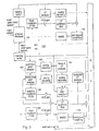
- Fig. 1 shows a schematic block diagram of a multicode coder. Audio signals are input at an audio signal input 10 of the multicode coder - called hereinafter also coder. From the input 10 the audio signals are provided to a first switch 20 and to a signal classifier 22. A bit rate input 30 which can be set to the relevant data bit rate also is connected to the signal classitier 22.
- the switch 20 can direct the input audio signals to either a time domain encoder 40 or a transform encoder 50.
- the digital output signal of the encoder 40 or the encoder 50 is then transferred over a channel depending on the position of a second switch 21.
- the switches 20, 21 are controlled by an output signal of the signal classifier 22.
- the multicode coder functions as follows:
- the input signal at signal input 10 is sampled at 16kHz and processed frame by frame based on a frame length of 320 samples (20 ms) using a lookahead of one frame.
- the coder thus has a coder delay of 40 ms, 20ms for the processed frame and 20ms for the lookahead frame, which can be stored temporarily in a buffer.
- the signal classifier 22 is used when the bandwidth input 30 indicates an available bit rate less than 32kb/sec, for example bit rates of 16 and 24kb/s, and classifies the audio signals so that the coder sends speech-type signals through the time domain encoder 40 and non-speech type signals, such as music or stationary background noise signals, through the transform encoder 50.
- the coder For a bit rate of 32kb/s or greater, the coder operates so that the coder always transfers signals through the transform encoder 50.
- the coder operates so that first the signal classifier 22 calculates a set of input parameters from the current audio frame, as shown in block 24. After that, a preliminary decision is computed using a set ofheuristically defined logical operations, as shown in block 26.
- the audio input signal which in this case may be bandwidth limited to 7kHz, i.e., to a wideband speech range, can be classified as speech or non-speech.
- the signal classifier 22 first computes two prediction gains, a first prediction gain being based on an LPC (linear prediction coefficients) analysis of the current input speech frame and a second prediction gain being based on a higher order LPC analysis of the previous input frames. Therefore the second prediction gain is similar to a backward LPC analysis based on coefficients that are derived from the input samples instead of synthesized output speech.
- LPC linear prediction coefficients
- An additional input parameter for the determining of a stationarity measure by the coder is the difference between previous and current LSF (line-spectrum frequency) coefficients, which are computed based on a LPC analysis of the current speech frame.
- the difference of the first and second prediction gains and the difference of the previous and current LSF coefficients are used to derive the stationarity measure, which is used as an indicator for the current frame being either music or speech.
- All the thresholds for the logical operations may be derived from the observation of a large amount of speech and music signals. Special conditions are checked for noisy speech.
- a final test procedure is performed in the signal classifier 22 to examine if the transition of one mode to another will lead to a smooth output signal at the decoder. In order to reduce complexity, this test procedure is performed on the input signal. If it is likely that switching will lead to an audible degradation, the decision to switch modes is delayed to the next frame.
- the transition scheme which forms the basis of the test procedure in block 28 is as follows: if the classifier 22 in block 26 decides to perform a transition from the transform mode to the time domain mode at frame n , the nth frame is the last frame to be computed by the transform scheme using a modified window function.
- the modified window function used for frames n and (n+1) is set to zero for the last 80 samples. This enables the transform coder to decode the leading 80 samples of frame (n+1). Otherwise, this would cause aliasing effects, because the overlapping of successive window functions is not possible without the transform coefficients of the next frame.
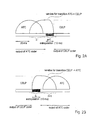
- Fig. 2a shows this transition for an ATC to a CELP mode change.
- the multicode decoder of the present invention has a digital signal input 80 for receiving the transmitted signals from the channel, an input swich 81, a time domain decoder 60, a transform decoder 70, an output switch 82 and an output 83.
- the first frame which is encoded by the transform scheme is frame number n.
- This transform encoding is done using a modified window function similar to the one used at the ATC to CELP transition shown in Fig. 2a, but reversed in time, as shown in Fig. 2b using ATC as an example of the transform scheme and CELP as an example of the time domain scheme. This enables the transform scheme to decode the last 80 samples of frame number n . The first 5 ms of this transition frame (number n ) can be decoded from the last transmitted time domain coefficients.
- Extrapolation is performed by calculating a residual signal of some of the previous synthesized output frames, which are extended according to pitch lag and then filtered using the LPC synthesis-filter.
- the LPC coefficients are computed by a backward LPC analysis of the last synthesized output frames.
- the open loop pitch calculation can be similar to that of a CELP coding scheme.
- extrapolation is performed for a length of 15 ms, where the last 5 ms of the extrapolated signal is weighted with a sine 2 -window function and added to the correspondingly weighted synthesized samples of the coding scheme used.
- the extrapolation is also applied in the test procedure in block 28 using only the input signal: If the extrapolated signal is very similar to the original input signal, the probability of a smooth transition at the decoder is high and the transition can be preformed. If not, the transition can be delayed.
- the transform and time domain coding schemes used in the encoders and decoders in Figs. 1 and 2 are modified ATC and CELP coding schemes, respectively.
- two additional mode bits are provided in the coding scheme for ATC/CELP changeover information. These two bits are taken from the bits typically used for the coding of the ATC-coefficients or from the bits for the CELP error protection, respectively.
- the four transmitted modes are: Mode 0 CELP mode (continue CELP mode) Mode 1 transition mode- ATC CELP Mode 2 transition mode: CELP ATC Mode 3 ATC mode (continue ATC mode).
- the two bits of information thus can identify the mode for the relevant frame.
- these 2 bits can be transmitted as well within those coding schemes.
- CELP and ATC is relevant as well to other time domain and transform domain coding techniques, respectively.
- the present invention also can provide error concealment for frame erasures. If a frame erasure occurs and the last frame was processed in mode 0 (for example CELP), then the CELP-mode will be kept for this frame. Otherwise, if the last frame was not processed in mode 0 , then the erased frame will be handled like an erased ATC frame.
- mode 0 for example CELP
- ATC-BFH ATC bad frame handling
- CELP-BFH bad frame handling
- the present invention preferably uses a CELP scheme as the time domain coding scheme performed by encoder 40 of Fig. 1.
- the CELP scheme can be a subband-CELP (SB-CELP) wideband source coding scheme for bit rates of 16kbit/s and 24kbit/s.
- SB-CELP subband-CELP
- Fig. 3 shows a block diagram of a SB-CELP encoder 140.
- the coding scheme is based on a split-band scheme with two unequal subbands using an ACELP (algebraic code excited linear prediction) codec in the lower subband.
- the CELP encoder 140 operates on a split-band scheme using two unequal subbands from 0-5kHz and 5-7kHz.
- the input signal is sampled at 16kHz and processed with a frame length of 320 samples (20 ms).
- a filterbank 142 performs unequal subband splitting and critical subsampling of the 2 subbands. Since the input signal typically is bandlimited to 7kHz, the sampling rate of the upper band can be reduced to 4kHz. At the output of the analysis filterbank 142, one frame of the upper band (5-7kHz) has 80 samples (20 ms). One frame of the lower band (0-5kHz) has 200 samples (20 ms), according to a sampling frequency of 10kHz. The delay of the analysis filterbank amounts to 5 ms.
- the 0-5kHz band is encoded using ACELP, taking place in lowerband subcoder 143.
- the subframe lengths used for the different parts of the codec are indicated in Table 1, being 5 ms for the LTP or adaptive codebook (ACB) and 1 ... 2.5 ms for the fixed codebook (FCB) parameters.
- a voicing mode can be switched every 10 ms.
- Linear prediction analysis within the lower band subcoder 143 occurs such that the short term (LP) synthesis filter coefficients are updated every 20 ms.
- different LP methods are used.
- N p 12
- an autocorrelation approach is applied to a windowed 30 ms segment of the signal input signal. A look-ahead of 5 ms is used.
- the quantization of the 12 forward LP parameters is performed in the LSF (Line Spectral Frequencies) domain using 33 bits.
- this backward mode need not be used, as the transform coding scheme can code stationary music passages.
- the LPC mode switch is based on the prediction gains of the forward and backward LPC filters and a stationarity indicator.
- a mode bit is transmitted to the decoder to indicate the LPC mode for the current frame.
- the synthesis filter parameters are linearly interpolated in the LSF domain.
- the backward mode is not used in the present invention, and thus the LPC mode switch always is set to choose the forward mode.
- the pitch analysis and adaptive codebook (ACB) search of the lower band coder 143 are as follows: depending on the voicing mode of the input signal, a long-term-prediction filter (LTP) is calculated by a combination of open-loop and closed-loop LTP analysis. For each 10 ms half of the frame (open-loop, or OL, frame), an open-loop pitch estimate is calculated in block 144 using a weighted correlation measure. Depending on this estimate and the input signal, a voicing decision at block 146 is taken and coded by a mode bit.
- LTP long-term-prediction filter
- a constrained closed-loop adaptive codebook search through the ACB in block 148 is performed around the open-loop estimate in the first and third ACB-subframe.
- a restricted search is performed around the pitch lag of the closed-loop analysis of the first or third ACB subframe, respectively.
- the pitch gain is nonuniformly scalar quantized with 4 bits. Therefore, the total bit rate of LTP amounts to 22 bits per OL frame.
- the following fixed codebook search through block 149 is used by the CELP scheme in subcoder 143.
- an excitation shape vector is selected from a ternary sparse codebook ("pulse codebook").
- An innovation vector contains 4 or 5 tracks with a total maximum of 10 or 12 nonzero pulses, resulting to bit rates of 25 to 34 bits to encode a shape vector.
- the FCB gain is encoded using fixed interframe MA prediction of the logarithmic energy of the scaled excitation vector.
- the prediction residual is nonuniformly scalar quantized using 4 or 5 bits, also depending on the available bit rate.
- an excitation shape vector is selected from either a sparse ternary algebraic codebook ("pulse codebook”) or a ternary algebraic codebook with constrained zero samples (“ternary codebook”).
- an innovation vector contains 2 tracks with a total maximum of 2 or 3 nonzero pulses, resulting to bit rates of 12, 14, or 16 bits to encode.
- a shape vector is encoded using 12, 14, or 16 bits, too. Both codebooks are searched for the optimum innovation and that codebook type is selected which minimizes the reconstruction error.
- the FCB mode is transmitted by a separate bit.
- the FCB gain is encoded using fixed interframe MA prediction of the logarithmic energy of the scaled excitation vector.
- the prediction residual is nonuniformly scalar quantized using 3 or 4 bits, also depending on the available bit rate.
- a perceptual weighting filter in block 150 is used during the minimization process of the ACB and FCB search (through minimum mean square error block 152).
- Different sets of weighting factors are used during the ACB and FCB search.
- the perceptual weighting filter is updated and interpolated as the LP synthesis filter.
- the weighting filter coefficients are computed from the unquantized LSF.
- the weighting filter typically is computed from the backward LP coefficients and extended by a tilt compensation section.
- Encoding of the upper band (5-7kHz) takes place in upper band subcoder 160 as follows.
- the upper band is not transmitted, and thus not encoded.
- the decimated upper subband is encoded using code-excited linear prediction (CELP) technique.
- CELP code-excited linear prediction
- the coder operates on signal frames of 20 ms (80 samples at a sampling rate of 4kHz).
- An upper band frame is divided into 5 excitation (FCB) subframes of length 16 samples (4 ms).
- FCB excitation
- LP short term
- an innovation shape vector of length 16 samples is chosen from a 10 bit stochastic Gaussian codebook.
- the FCB gain is encoded using fixed interframe MA prediction, with the residual being nonuniformly scalar quantized with 3 bits.
- Fig. 4 shows a CELP decoder 180 for decoding received CELP encoded signals.
- the decoding of the 0-5kHz band takes place in a lower band subdecoder 182 such that the total excitation is constructed from the received (adaptive and fixed) codebook indices and codeword gains, depending on the mode and the bit rate.
- This excitation is passed through the LP synthesis filter 188 and an adaptive postfilter 189.
- either the received LP coefficients are used for the LP synthesis filter during the forward modes; or, for the backward modes, a high order filter is computed from the previously synthesized signal before postfiltering.
- the adaptive postfilter 189 has a cascade of a format postfilter, a harmonic postfilter, and a tilt compensation filter. After postfiltering, an adaptive gain is performed. The postfilter is not active during backward LPC mode.
- the 5-7kHz band is decoded in upper band subdecoder 184 as follows. At 16kb/s, no upper band parameters have been transmitted. The upper band output signal is set to zero by the decoder.
- the received parameters are decoded. Every 4 ms, a vector of 16 samples is generated from the received FCB entry and a gain is computed using the received residual and the locally predicted estimate. This excitation is passed through the LP synthesis filter 185.
- a synthesis filterbank 181 After decoding the two subband signals, a synthesis filterbank 181 provides unsampling, interpolation and a delay compensated superposition of these signals, having the inverse structure as the analysis filterbank.
- the synthesis filterbank contributes 5 ms of delay.
- Bit error concealment is provided by the decoder 180. Depending on the bit rate and mode, different numbers of (parity) bits are available. Single parity bits are assigned to particular codec parameters, in order to locate errors and to take dedicated interpolative measures for concealment. Bit error protection is important especially for the LPC mode bit, the LP coefficients, pitch lags and fixed codebook gains.
- Frame erasure concealment also is provided.
- the LP synthesis filter of the previous frame is re-used.
- a pitch-synchronous or an asynchronous extrapolation of the previous excitation is constructed and used for synthesizing the signal in the current, lost frame.
- an attenuation of the excitation is performed.
- Tables 2 and 3 give the bit allocation for the 16 and 24kbit/s modes, respectively, of the CELP scheme of Fig. 3.
- Bit allocation for a 20 ms frame of the 16kbit/s mode codec 16kbit/s Parameter allocated bits lower band LPC mode 1 voicing mode 2 LP coeff. 33
- ACB lag (0 or 14) + (0 or 14)
- ACB gain (0 or 8) + (0 or 8)
- FCB shape 100, 120 or 136) + (100, 120 or 136)
- the transform coding scheme performed by the transform encoder 50 of Fig. 1 preferably is an ATC coding scheme, which operates as follows:
- Transform coding is the only mode for a 32kbit/s bit rate. For lower bit rates it is used in conjunction with the time domain coding technique in the multicode coder.
- the ATC encoder may be based on an MDCT transform, which exploits psychoacoustical results by the use of masking curves calculated in the transform domain. Those curves are employed to allocate dynamically the bit rate of the transform coefficients.
- the ATC encoder 50 is depicted in Fig. 5.
- the input signal sampled at 16kHz is divided into 20-ms frames.
- 320 MDCT coefficients of the MDCT transform are calculated, as shown in block 51, with a window overlapping two 20 ms successive frames.
- a tonality detector 52 evaluates whether the input signal is tonal or not, this binary information (t/nt) is transmitted to the decoder.
- a voiced/unvoiced detector 53 outputs the v/uv information.
- a masking curve is calculated at block 54 using the transform coefficients, and coefficients below the mask minus a given threshold are cleared.
- the spectrum envelope of the current frame is estimated at block 55, divided into 32 bands whose energies are quantized, encoded using entropy coding and transmitted to the decoder.
- the quantization of the spectrum envelope depends on the tonal/non tonal and voiced/unvoiced nature of the signal.
- a dynamic allocation of the bits for the coefficients encoding is performed at block 56.
- This allocation uses the decoded spectrum envelope and is performed both by the encoder 50 and the decoder. This avoids transmitting any information on the bit allocation.
- the transform coefficients are then quantized at block 57 using the decoded spectrum envelope to reduce the dynamic range of the quantizer. Multiplexing is provided at block 58.
- a local decoding is included.
- the local decoding scheme follows valid frame decoding, shown in block 71 in Fig. 6.
- the actual decoding of the quantization indices is generally not needed, the decoded value being a by-product of the quantization process.
- the MDCT coefficients, denoted y(k), of each frame are computed using the expression that can be found in "High-Quality Audio Transform Coding at 64Kbps," by Y. Mahieux & J.P. Petit, IEEE Trans. on Communications Vol. 42, No. 1, Nov. 1994, which is hereby incorporated by reference herein.
- the coefficients in the range [289,319] receive the value 0 and are not encoded. For a 16kb/s bit rate, because of the 5kHz low-pass limitation, this non-encoded range is extended to the coefficients [202,319].
- a conventional voiced/unvoiced detection at block 53 in Fig. 5 is performed on the current input signal x(n), using the average frame energy, the 1 st parcor value, and the number of zero crossings.
- a measure of the tonal or non-tonal nature of the input signal also is performed at block 52 on the MDCT coefficients.
- a spectrum flatness measure sfm is first evaluated as the logarithm of the ratio between the geometric mean and the arithmetic mean of the squared transform coefficients.
- a smoothing procedure is applied to the sfm to avoid abrupt changes.
- the resulting value is compared to a fixed threshold to decide whether the current frame is tonal or not.
- Masked coefficients also can be detected at block 54.
- the masking curve computation can follow the algorithm presented in "High-Quality Audio Transform Coding at 64Kbps," by Y. Mahieux & J.P. Petit cited above.
- a masking threshold is calculated for every MDCT coefficient.
- the algorithm uses a psychoacoustical model that gives a masking curve expression on the Bark scale.
- the frequency range is divided into 32 bands non-uniformly spaced along the frequency axis, as shown in Table 4. All the frequency depending parameters are assumed to be constant over each band, translated into the transform coefficients frequency grid, and stored.
- Each coefficient y(k) is considered as masked when its squared value is below the threshold.
- Definition of the MDCT 32 bands BAND Upper bound (Hz) Nb. Of coefficients BAND Upper bound (HZ) Nb. of coefficients 0 75 3 16 2375 10 1 150 3 17 2625 10 2 225 3 18 2875 10 3 300 3 19 3175 12 4 375 3 20 3475 12 5 475 4 21 3775 12 6 575 4 22 4075 12 7 675 4 23 4400 13 8 800 5 24 4725 13 9 925 5 25 5050 13 10 1050 5 26 5400 14 11 1225 7 27 5750 14 12 1425 8 28 6100 14 13 1650 9 29 6475 15 14 1875 9 30 6850 15 15 2125 10 31 7225 15
- a spectrum envelope is computed for each band at block 55.
- the quantization of the values e(j) is different for tonal and for non-tonal frames.
- the 32 decoded values of the spectrum envelope will be denoted e'(j) .
- the values e(j) are quantized in the log domain.
- the first log value is quantized using a 7 bits uniform quantizer.
- the next bands are differentially encoded using a uniform log quantizer on 32 levels.
- An entropy coding method is then employed to encode the quantized values, with the following features:
- the band with the maximum energy is first looked for, its number is encoded on 5 bits and the associated value on 7 bits.
- the other bands are differentially encoded relative to this maximum, in the log domain, on 4 bits.
- the bits of the coefficients are dynamically allocated according to their perceptual importance.
- the basis of this allocation can be for example according to the allocation described in "High-Quality Audio Transform Coding at 64Kbps," by Y. Mahieux & J.P. Petit, cited above.
- the process is performed both at the ATC encoder and the ATC decoder side.
- a masking curve is calculated on a band per band basis, using the decoded spectrum envelope.
- the bit allocation is obtained by an iterative procedure where at each iteration, for each band, the bit rate per coefficient R(f) is evaluated, then approximated to satisfy the coefficients' quantizers constraints. At the end of each iteration the global coefficients bit rate R' 0 , is calculated. The iterative procedure stops whenever this value is closed to the target R' 0 , or when a maximum number of iterations is reached.
- the bit allocation is readjusted either by adding bit rate to the most perceptually important bands or by subtracting bit rate to the less perceptually important bands.
- Quantization and encoding of the MDCT coefficients occurs in block 57.
- the value actually encoded for a coefficient k of a band j is y(k) / e'(j).
- the quantizers For the scalar quantizers, two classes of quantizers may be designed depending on the v/uv nature of the frames.
- the masked coefficients receive the null value. This is allowed by the use of quantizers having zero as reconstruction level. Since the symmetry is needed, the quantizers were chosen to have an odd number of levels. This number ranges from 3 to 31.
- the codebooks are embedded and designed for dimensions 3 to 15.
- the codebooks (corresponding to various bit rates from 5 to 32, depending of the dimension) are composed of the union of permutation codes, all sign combinations being possible.
- the quantization process may use an optimal fast algorithm (for example as described in Quantification vectorielle algébrique sphérique par le distrus de Barnes-Wall. Application au codage de la Parole , C. Lamblin, Ph.D, University of Sherbrooke, March 1988, hereby incorporated by reference herein) that takes advantage of the permutation codes structure.
- the encoding of the selected codebook entry may use Schalkwijk's algorithm (as for example in Quantification vectorielle algébrique sphérique par le distrus de Barnes-Wall. Application au codage de la Parole cited above) for the permutations the signs being separately encoded.
- Bitstream packing for the scalar codes is performed before the coefficients quantization begins.
- the numbers of levels for the coefficients belonging to the scalar quantized bands are first ordered according to decreasing perceptual importance of the bands. Those numbers of levels are iteratively multiplied together until the product reaches a value closed to a power of 2, or (2 32 -1). The corresponding coefficients quantization indices are jointly encoded. The process restarts from the first discarded number of level. At the end of the process the number of bits taken by the obtained codes is calculated. If it is greater than the allowed value, bit rate is decreased using the readjustment method mentioned above by subtracting bit rate to the less perceptually important bands. Bit rate taken to the bands encoded using vector quantizers does not affect bitstream packing.
- bitstream-packing algorithm should be restarted from the first code where a modification occurs. Since the bitstream-packing algorithm has ordered the number of levels according to decreasing importance of the bands, less important bands, that are more likely to be affected, were packed at the end of the procedure, which reduces the complexity of the bitstream packing.
- the bitstream-packing algorithm generally converges at the second iteration.
- the bits corresponding to the spectrum envelope, voiced/unvoiced and tonal/non tonal decisions are protected against isolated transmission errors using 9 protection bits.
- the global bit allocation for the ATC mode is given by Table 5.
- the spectrum envelope has a variable number of bits due to entropy coding, typically in the range [85-90].
- the number of bits allocated to the coefficients is equal to the total number of bits (depending on bit rate) minus the other numbers of bits.
- Bit allocation v/uv 1 bit t/nt 1 bit Spectrum envelope variable number of bits Coefficients variable number of bits Protection bits 9 bits
- the ATC decoder is shown in Fig. 6. Two modes of operation are run according to the bad frame indicator (BFI).
- BFI bad frame indicator
- the decoding scheme in valid frame decoder 71 follows the operation order as described with respect to Fig. 6.
- An inverse MDCT transform at block 73 is performed on the decoded MDCT coefficients and the synthesis signal is obtained in the time domain by the add-overlap of the sine-weighted samples of the previous and the current frame.
- the valid frame decoder operates first through a demultiplexor 74.
- Spectrum envelope decoding occurs at block 75 for non-tonal and tonal frames.
- the quantizer indices of the bands following the first one are obtained by comparing in decreasing probabilities order the bitstream to the Huffmann codes contained in stored tables.
- the encoding process described above is reversed. Dynamic allocation in block 76 and inverse quantification of the MDCT coefficients in block 77 also takes place as in the encoder.
- the error concealment procedure in block 72 of Fig. 6 is shown in Fig. 8.
- the missing MDCT coefficients are calculated using extrapolated values of the output signal.
- the treatment differs for the first erased frame and the following successive frames.
- the procedure is as follows:
- the LPC and the LTP coefficients calculated at the first erased frame are kept and only 320 samples of new extrapolated signal are calculated.
Landscapes
- Engineering & Computer Science (AREA)
- Computational Linguistics (AREA)
- Signal Processing (AREA)
- Health & Medical Sciences (AREA)
- Audiology, Speech & Language Pathology (AREA)
- Human Computer Interaction (AREA)
- Physics & Mathematics (AREA)
- Acoustics & Sound (AREA)
- Multimedia (AREA)
- Compression, Expansion, Code Conversion, And Decoders (AREA)
- Transmission Systems Not Characterized By The Medium Used For Transmission (AREA)
- Stereo-Broadcasting Methods (AREA)
Abstract
Description
- The present invention relates to a method and device for coding audio signals.
- Audio signals, such as speech, background noise and music, can be converted to digital data using audio coding schemes. Input audio signals typically are sampled a certain frequency, and are assigned a number of bits per sample according to the audio coding scheme used. The bits, as digital data, then can be transmitted. After transmission, a decoder can decode the digital data, and output an analog signal, to, for example, a loudspeaker.
- One coding scheme, PCM (pulse-code modulation), may sample telephone speech (typically 300-3400 Hz) at 8kHz and require 8 PCM bits per sample, resulting in a 64kb/sec digital stream. With PCM wideband speech (typically 60-7000kHz) may be sampled at 16kHz and assigned 14 PCM bits per sample, resulting in a PCM bit rate of 224kb/s. And wideband audio (typically 10-20,000 Hz) may be sampled at 48kHz and assigned 16 PCM bits per sample, resulting in a PCM bit rate of 768kb/s.
- As described in "The ISDN Studio" by Dave Immer, Audio Engineering Society 99th Convention, Oct. 8, 1995, New York City, other audio coding techniques can be used to achieve bit rates smaller than the PCM bit rates. These audio coding schemes disregard irrelevant or redundant information and fall into two basic categories: transform (frequency domain) based schemes and time domain (predictive) based schemes. A frequency domain based scheme employs bit reduction using known characteristics (contained in an on-board lookup table) of human hearing. This bit reduction process is also known as perceptual coding. Psychoacoustic waveform information is transmitted by the digital data and reconstructed at a decoder. Aliasing noise typically is masked within subbands which contain the most energy. Audio frequency response for frequency domain coding is much less bit rate dependent than a time domain process. However, more coding delay may result.
- Time domain coding techniques use predictive analysis based on look-up tables available to the encoder, and transmit differences between a prediction and an actual sample. Redundant information can be added back at the decoder. With time domain based coding techniques, audio frequency response is dependent on the bit rate. However, a very low coding delay results.
- One time domain based coding scheme is CELP (code-excited linear prediction). CELP can be used to code telephone speech signals using as low as a 16kb/s data rate. The input speech may be divided into frames at an 8kHz sampling rate. Using a codebook of excitation waveforms and a closed-loop search mechanism for identifying the best excitation waveform for each frame, the CELP algorithm can provide the equivalent of 2 bits per sample to adequately code the speech, so that a bit rate of 16kb/s is achieved. With wideband speech up to 7kHz, a 16kHz sampling may be used, also with the equivalent of 2 bits per sample, so that a bit rate of 32kb/s can be achieved.
- CELP has the advantage that speech signals can be transmitted at low bit rates, even at 16kb/sec.
- One transform coding scheme is ATC (adaptive transform coder). Audio signals are received sampled, and divided into frames. A transform, such as MDCT (modified discrete cosign transform), is performed on the frames, so that transform coefficients may be computed. The calculation of the coefficients using MDCT is explained, for example, in "High-Quality Audio Transform Coding at 64Kbps," by Y. Mahieux & J.P. Petit, IEEE Trans. on Communications. Vol. 42, No. 11, Nov. 1994, which is hereby incorporated by reference herein. The MDCT coefficients then can be bit coded, and transmitted digitally.
- ATC coding has the advantage of providing high quality audio transmission for signals such as music and background noise.
- To date, typically only one type of coding technique has been used to code input audio signals in a codec system. However, especially at low bit rates, this does not lead to an optimal transfer of audio signals due to the limitations of time domain and transform coding techniques.
- The present invention provides for the use of both frequency and time domain coding at different times, so that, depending on the available bandwidth, digital transfer of audio signals can be optimized.
- The present invention thus provide a method for signal controlled switching comprising:
- receiving input audio signals;
- classifying a first set of the input audio signals as speech or non-speech signals;
- coding the speech signals using a time domain coding scheme; and
- coding the nonspeech signals using a transform coding scheme.
-
- The time domain coding scheme preferably is a CELP coding scheme and the transform coding scheme a ATC coding scheme. The method of the present invention thus can use an ATCELP coder which is a combination of an ATC coding scheme and a CELP coding scheme.
- The time domain coding scheme is used mainly for speech signals and the transform coding scheme is used mainly for music and stationary background noise signals, thus providing advantages of both types of coding schemes.
- The present method preferably is used only when a bandwidth of less than 32kb/sec is available, for example 16kb/sec or 24kb/sec. For a bit rate of 32kb/s or higher, only the transform mode of a multicode coder then is used.
- The present invention also provides a multicode coder comprising:
- an audio signal input; and
- a switch for receiving the audio signal inputs, the switch having a time domain encoder, a transform encoder, and a signal classifier for classifying the audio signals generally as speech or non-speech, the signal classifier directing speech audio signals to the time domain encoder and non-speech audio signals to the transform encoder.
-
- The time domain encoder preferably is a CELP encoder and the transform encoder an ATC encoder. The change between these two coding techniques (CELP and ATC) is controlled by the signal classifier, which works exclusively on the audio input signal. The chosen mode (speech or non-speech) of the signal classifier can be transmitted as side information to the decoder.
- The present invention also provides a multicode decoder having a transform decoder, a time domain decoder and an output switch for switching signals between the transform and time domain decoders.
- Further improvements and variations of the invention are specified in dependent claims.
- The present invention may be understood in conjunction with the drawings, in which:
- Fig. 1 shows a multicode coder according to the present invention;
- Fig. 2 shows a multicode decoder according to the present invention;
- Figs. 2a and 2b show the functioning of a multicode decoder according to the present invention during transitions between an ATC mode and a CELP mode.
- Fig. 3 shows a block diagram of a CELP encoder of the present invention;
- Fig. 4 shows a block diagram of the CELP decoder of the present invention;
- Fig. 5 shows a block diagram of the ATC encoder of the present invention;
- Fig. 6 shows a block diagram of the ATC decoder of the present invention;
- Fig. 7 shows a block diagram of the valid frame decoder shown in Fig. 6; and
- Fig. 8 shows a block diagram of the error concealment unit shown in Fig. 6.
-
- Fig. 1 shows a schematic block diagram of a multicode coder. Audio signals are input at an
audio signal input 10 of the multicode coder - called hereinafter also coder. From theinput 10 the audio signals are provided to afirst switch 20 and to asignal classifier 22. Abit rate input 30 which can be set to the relevant data bit rate also is connected to thesignal classitier 22. - The
switch 20 can direct the input audio signals to either atime domain encoder 40 or atransform encoder 50. - The digital output signal of the
encoder 40 or theencoder 50 is then transferred over a channel depending on the position of asecond switch 21. Theswitches signal classifier 22. - The multicode coder functions as follows:
- The input signal at
signal input 10 is sampled at 16kHz and processed frame by frame based on a frame length of 320 samples (20 ms) using a lookahead of one frame. The coder thus has a coder delay of 40 ms, 20ms for the processed frame and 20ms for the lookahead frame, which can be stored temporarily in a buffer. - The
signal classifier 22 is used when thebandwidth input 30 indicates an available bit rate less than 32kb/sec, for example bit rates of 16 and 24kb/s, and classifies the audio signals so that the coder sends speech-type signals through thetime domain encoder 40 and non-speech type signals, such as music or stationary background noise signals, through thetransform encoder 50. - For a bit rate of 32kb/s or greater, the coder operates so that the coder always transfers signals through the
transform encoder 50. - For lower bit rates of 16 and 24kb/s, the coder operates so that first the
signal classifier 22 calculates a set of input parameters from the current audio frame, as shown inblock 24. After that, a preliminary decision is computed using a set ofheuristically defined logical operations, as shown inblock 26. - Finally as shown in
block 28, a postprocessing procedure is applied to guarantee that switching is performed only during frames that allow a smooth transition from one mode to another. - The audio input signal, which in this case may be bandwidth limited to 7kHz, i.e., to a wideband speech range, can be classified as speech or non-speech. At
block 24, thesignal classifier 22 first computes two prediction gains, a first prediction gain being based on an LPC (linear prediction coefficients) analysis of the current input speech frame and a second prediction gain being based on a higher order LPC analysis of the previous input frames. Therefore the second prediction gain is similar to a backward LPC analysis based on coefficients that are derived from the input samples instead of synthesized output speech. - An additional input parameter for the determining of a stationarity measure by the coder is the difference between previous and current LSF (line-spectrum frequency) coefficients, which are computed based on a LPC analysis of the current speech frame.
- As shown schematically in
block 26, the difference of the first and second prediction gains and the difference of the previous and current LSF coefficients are used to derive the stationarity measure, which is used as an indicator for the current frame being either music or speech. All the thresholds for the logical operations may be derived from the observation of a large amount of speech and music signals. Special conditions are checked for noisy speech. - As shown schematically in
block 28, before any switch between the time domain mode and the transform mode occurs, a final test procedure is performed in thesignal classifier 22 to examine if the transition of one mode to another will lead to a smooth output signal at the decoder. In order to reduce complexity, this test procedure is performed on the input signal. If it is likely that switching will lead to an audible degradation, the decision to switch modes is delayed to the next frame. - The transition scheme, which forms the basis of the test procedure in
block 28 is as follows: if theclassifier 22 inblock 26 decides to perform a transition from the transform mode to the time domain mode at frame n, the nth frame is the last frame to be computed by the transform scheme using a modified window function. The modified window function used for frames n and (n+1) is set to zero for the last 80 samples. This enables the transform coder to decode the leading 80 samples of frame (n+1). Otherwise, this would cause aliasing effects, because the overlapping of successive window functions is not possible without the transform coefficients of the next frame. In the (n+1)th frame, where the time domain mode is performed for the first time, only the last ms can be encoded by the time domain coder (caused by a filterbank delay), so that in thisframe 10 ms of the speech signal will have to be extrapolated at the decoder side. - Fig. 2a shows this transition for an ATC to a CELP mode change. As can be seen, in the (n+1)th frame, the first 5ms of the frame are ATC encoded and the last 5ms of the frame are CELP encoded. The extrapolation for the 10ms takes place in the multicode decoder. As shown in Fig. 2, the multicode decoder of the present invention has a
digital signal input 80 for receiving the transmitted signals from the channel, aninput swich 81, atime domain decoder 60, atransform decoder 70, anoutput switch 82 and an output 83. - If the
signal classifier 22 inblock 26 of Fig. 1 decides to perform a transition from the time domain mode to the transform mode at input frame n, the first frame which is encoded by the transform scheme is frame number n. This transform encoding is done using a modified window function similar to the one used at the ATC to CELP transition shown in Fig. 2a, but reversed in time, as shown in Fig. 2b using ATC as an example of the transform scheme and CELP as an example of the time domain scheme. This enables the transform scheme to decode the last 80 samples of frame number n. The first 5 ms of this transition frame (number n) can be decoded from the last transmitted time domain coefficients. - Therefore extrapolation at the decoder also is performed for a length of 10 ms, as shown in Fig. 2b.
- Extrapolation is performed by calculating a residual signal of some of the previous synthesized output frames, which are extended according to pitch lag and then filtered using the LPC synthesis-filter. The LPC coefficients are computed by a backward LPC analysis of the last synthesized output frames. The open loop pitch calculation can be similar to that of a CELP coding scheme.
- To avoid discontinuities at the end of the extrapolated signal, extrapolation is performed for a length of 15 ms, where the last 5 ms of the extrapolated signal is weighted with a sine2-window function and added to the correspondingly weighted synthesized samples of the coding scheme used.
- The extrapolation is also applied in the test procedure in
block 28 using only the input signal: If the extrapolated signal is very similar to the original input signal, the probability of a smooth transition at the decoder is high and the transition can be preformed. If not, the transition can be delayed. - Preferably, the transform and time domain coding schemes used in the encoders and decoders in Figs. 1 and 2 are modified ATC and CELP coding schemes, respectively. In these schemes two additional mode bits are provided in the coding scheme for ATC/CELP changeover information. These two bits are taken from the bits typically used for the coding of the ATC-coefficients or from the bits for the CELP error protection, respectively.
- The four transmitted modes are:
Mode 0 CELP mode (continue CELP mode) Mode 1transition mode- ATC CELP Mode 2 transition mode: CELP ATC Mode 3 ATC mode (continue ATC mode). - The two bits of information thus can identify the mode for the relevant frame. Of course, for coding schemes other than ATC and CELP, these 2 bits can be transmitted as well within those coding schemes. Thus the following description with respect to CELP and ATC is relevant as well to other time domain and transform domain coding techniques, respectively.
- The present invention also can provide error concealment for frame erasures. If a frame erasure occurs and the last frame was processed in mode 0 (for example CELP), then the CELP-mode will be kept for this frame. Otherwise, if the last frame was not processed in mode 0, then the erased frame will be handled like an erased ATC frame.
- If a frame indicating a transition from ATC to CELP (i.e., mode 1) is erased, an ATC bad frame handling (ATC-BFH) will be used, since the previous frame was an ATC (mode 3)- frame. However, since the following non-erased frame is already a CELP frame (mode 0), a signal extrapolation covering 15 ms should be performed.
- One the other hand, if a frame indicating a transition from CELP to ATC (i.e., mode 2) is erased, a CELP-BFH (bad frame handling) operation is used. Upon the detection of the following non-erased frame, which is in ATC mode (mode 3), an extra ATC-BFH has to be performed in order to enable the decoding of the non-erased ATC frame.
- The frame erasure concealments of each individual coding scheme are described further below.
- As stated above, the present invention preferably uses a CELP scheme as the time domain coding scheme performed by
encoder 40 of Fig. 1. The CELP scheme can be a subband-CELP (SB-CELP) wideband source coding scheme for bit rates of 16kbit/s and 24kbit/s. - Fig. 3 shows a block diagram of a SB-
CELP encoder 140. The coding scheme is based on a split-band scheme with two unequal subbands using an ACELP (algebraic code excited linear prediction) codec in the lower subband. TheCELP encoder 140 operates on a split-band scheme using two unequal subbands from 0-5kHz and 5-7kHz. The input signal is sampled at 16kHz and processed with a frame length of 320 samples (20 ms). - A
filterbank 142 performs unequal subband splitting and critical subsampling of the 2 subbands. Since the input signal typically is bandlimited to 7kHz, the sampling rate of the upper band can be reduced to 4kHz. At the output of theanalysis filterbank 142, one frame of the upper band (5-7kHz) has 80 samples (20 ms). One frame of the lower band (0-5kHz) has 200 samples (20 ms), according to a sampling frequency of 10kHz. The delay of the analysis filterbank amounts to 5 ms. - The 0-5kHz band is encoded using ACELP, taking place in
lowerband subcoder 143. The subframe lengths used for the different parts of the codec are indicated in Table 1, being 5 ms for the LTP or adaptive codebook (ACB) and 1 ... 2.5 ms for the fixed codebook (FCB) parameters. A voicing mode can be switched every 10 ms.Update of the lower band codec parameters (in samples, f s = 10kHz) Parameter name of update period length of update period 16kbit/s 24kbit/s LPC frame 200 (20 ms) LTP mode open-loop frame 100 (10 ms) ACB parameters ACB subframe 50 (5 ms) FCB parameters FCB subframe 25 (2.5 ms) 10 (1.0 ms) - Linear prediction analysis within the
lower band subcoder 143 occurs such that the short term (LP) synthesis filter coefficients are updated every 20 ms. Depending on tile input signal characteristics, different LP methods are used. For speech and strongly unstationary music passages, the forward mode throughblock 147 is chosen, i.e., a low order (N p = 12) LP model is computed from the current frame and the coefficients are transmitted. To obtain the LP parameters, an autocorrelation approach is applied to a windowed 30 ms segment of the signal input signal. A look-ahead of 5 ms is used. The quantization of the 12 forward LP parameters is performed in the LSF (Line Spectral Frequencies) domain using 33 bits. Particularly for rather stationary music passages, typically the backward mode, a high order LP filter (N p = 52) would be adapted from a 35 ms segment of the previously synthesized signal. Therefore, no further LP parameter information has to be transmitted. However, with the multicode coder of the present invention this backward mode need not be used, as the transform coding scheme can code stationary music passages. - The LPC mode switch is based on the prediction gains of the forward and backward LPC filters and a stationarity indicator. A mode bit is transmitted to the decoder to indicate the LPC mode for the current frame. In the forward LPC mode, the synthesis filter parameters are linearly interpolated in the LSF domain. As stated, the backward mode is not used in the present invention, and thus the LPC mode switch always is set to choose the forward mode.
- The pitch analysis and adaptive codebook (ACB) search of the
lower band coder 143 are as follows: depending on the voicing mode of the input signal, a long-term-prediction filter (LTP) is calculated by a combination of open-loop and closed-loop LTP analysis. For each 10 ms half of the frame (open-loop, or OL, frame), an open-loop pitch estimate is calculated inblock 144 using a weighted correlation measure. Depending on this estimate and the input signal, a voicing decision atblock 146 is taken and coded by a mode bit. - Provided an OL frame declared voiced, a constrained closed-loop adaptive codebook search through the ACB in
block 148 is performed around the open-loop estimate in the first and third ACB-subframe. In the second and fourth ACB-subframe a restricted search is performed around the pitch lag of the closed-loop analysis of the first or third ACB subframe, respectively. - This procedure results in a delta encoding scheme leading to 8+6=14 bits per OL frame for coding the pitch lags in the range of 25...175. A fractional pitch approach is used.
- For each ACB subframe, the pitch gain is nonuniformly scalar quantized with 4 bits. Therefore, the total bit rate of LTP amounts to 22 bits per OL frame.
- For bit rates of 16kb/s, the following fixed codebook search through
block 149 is used by the CELP scheme insubcoder 143. - Every 2.5ms (25 samples), an excitation shape vector is selected from a ternary sparse codebook ("pulse codebook").
- Depending on the bit rate available for the excitation, i.e., depending on the settings of the LPC mode and voicing mode switches, different configurations of the algebraic codebook are selected:
- An innovation vector contains 4 or 5 tracks with a total maximum of 10 or 12 nonzero pulses, resulting to bit rates of 25 to 34 bits to encode a shape vector. The FCB gain is encoded using fixed interframe MA prediction of the logarithmic energy of the scaled excitation vector. The prediction residual is nonuniformly scalar quantized using 4 or 5 bits, also depending on the available bit rate.
- At bit rates of 24kb/s, the following fixed codebook search is used:
- Every 1 ms (10 samples), an excitation shape vector is selected from either a sparse ternary algebraic codebook ("pulse codebook") or a ternary algebraic codebook with constrained zero samples ("ternary codebook").
- Depending on the bit rate available for the excitation, i.e., depending on the settings of the LPC mode and voicing mode switches, different configurations of the algebraic codebooks are selected. For the pulse codebook, an innovation vector contains 2 tracks with a total maximum of 2 or 3 nonzero pulses, resulting to bit rates of 12, 14, or 16 bits to encode. For the ternary codebook, a shape vector is encoded using 12, 14, or 16 bits, too. Both codebooks are searched for the optimum innovation and that codebook type is selected which minimizes the reconstruction error. For each FCB subframe, the FCB mode is transmitted by a separate bit. The FCB gain is encoded using fixed interframe MA prediction of the logarithmic energy of the scaled excitation vector. The prediction residual is nonuniformly scalar quantized using 3 or 4 bits, also depending on the available bit rate.
- A perceptual weighting filter in
block 150 is used during the minimization process of the ACB and FCB search (through minimum mean square error block 152). This filter has a transfer function of the form W (z) = A (z/ 1 ) / A(z/ 2), with A (z) being the LP analysis filter. Different sets of weighting factors are used during the ACB and FCB search. The perceptual weighting filter is updated and interpolated as the LP synthesis filter. In the forward LPC mode, the weighting filter coefficients are computed from the unquantized LSF. (In the backward LPC mode, the weighting filter typically is computed from the backward LP coefficients and extended by a tilt compensation section.) - Encoding of the upper band (5-7kHz) takes place in
upper band subcoder 160 as follows. - For bit rates of 16kb/s, the upper band is not transmitted, and thus not encoded.
- At 24kb/s, the decimated upper subband is encoded using code-excited linear prediction (CELP) technique.
- The coder operates on signal frames of 20 ms (80 samples at a sampling rate of 4kHz). An upper band frame is divided into 5 excitation (FCB) subframes of length 16 samples (4 ms). The short term (LP) synthesis filter coefficients for a model order of N p = 8 are computed applying a Burg covariance approach to a input segment of length 160 (40 ms) and quantized with 10 bits.
- From the LP parameters, a perceptual weighting filter (indicated at block 162) having a transfer function of the form W(z) = A (z/ 1 ) / A(z/ 2 ), with A(z) representing the inverse LP filter, is computed for the fixed codebook (FCB) search.
- In the upper band FCB search, an innovation shape vector of length 16 samples is chosen from a 10 bit stochastic Gaussian codebook. The FCB gain is encoded using fixed interframe MA prediction, with the residual being nonuniformly scalar quantized with 3 bits.
- Fig. 4 shows a CELP decoder 180 for decoding received CELP encoded signals. The decoding of the 0-5kHz band takes place in a
lower band subdecoder 182 such that the total excitation is constructed from the received (adaptive and fixed) codebook indices and codeword gains, depending on the mode and the bit rate. This excitation is passed through theLP synthesis filter 188 and anadaptive postfilter 189. - According to the encoder procedures, either the received LP coefficients are used for the LP synthesis filter during the forward modes; or, for the backward modes, a high order filter is computed from the previously synthesized signal before postfiltering.
- The
adaptive postfilter 189 has a cascade of a format postfilter, a harmonic postfilter, and a tilt compensation filter. After postfiltering, an adaptive gain is performed. The postfilter is not active during backward LPC mode. - The 5-7kHz band is decoded in
upper band subdecoder 184 as follows. At 16kb/s, no upper band parameters have been transmitted. The upper band output signal is set to zero by the decoder. - At 24kbit/s, the received parameters are decoded. Every 4 ms, a vector of 16 samples is generated from the received FCB entry and a gain is computed using the received residual and the locally predicted estimate. This excitation is passed through the
LP synthesis filter 185. - After decoding the two subband signals, a
synthesis filterbank 181 provides unsampling, interpolation and a delay compensated superposition of these signals, having the inverse structure as the analysis filterbank. The synthesis filterbank contributes 5 ms of delay. - Bit error concealment is provided by the decoder 180. Depending on the bit rate and mode, different numbers of (parity) bits are available. Single parity bits are assigned to particular codec parameters, in order to locate errors and to take dedicated interpolative measures for concealment. Bit error protection is important especially for the LPC mode bit, the LP coefficients, pitch lags and fixed codebook gains.
- Frame erasure concealment also is provided. When a frame erasure is detected, the LP synthesis filter of the previous frame is re-used. Based on a voiced/unvoiced decision of the previous frame, either a pitch-synchronous or an asynchronous extrapolation of the previous excitation is constructed and used for synthesizing the signal in the current, lost frame. For subsequent lost frames, an attenuation of the excitation is performed.
- Tables 2 and 3 give the bit allocation for the 16 and 24kbit/s modes, respectively, of the CELP scheme of Fig. 3.
Bit allocation for a 20 ms frame of the 16kbit/s mode codec 16kbit/s Parameter allocated bits lower band LPC mode 1 voicing mode 2 LP coeff. 33 ACB lag (0 or 14) + (0 or 14) ACB gain (0 or 8) + (0 or 8) FCB shape (100, 120 or 136) + (100, 120 or 136) FCB gain (16 or 18) + (16 or 18) upper band - error protection 1 ... 9 Total 320 Bit allocation for a 20 ms frame of the 24kbit/s mode codec 24kbit/s Parameter allocated bits lower band LPC mode 1 voicing mode 2 LP coeff. 33 ACB lag (0 or 14) + (0 or 14) ACB gain (0 or 8) + (0 or 8) FCB mode 20 FCB shape (120, 140 or 160) + (120, 140 or 160) FCB gain (31, 32, 33 or 34) + (31, 32, 33 or 34) upper band LP coeff. 10 FCB shape 40 FCB gain 15 error protection 4 ... 11 Total 480 - The transform coding scheme performed by the
transform encoder 50 of Fig. 1 preferably is an ATC coding scheme, which operates as follows: - Transform coding is the only mode for a 32kbit/s bit rate. For lower bit rates it is used in conjunction with the time domain coding technique in the multicode coder.
- The ATC encoder may be based on an MDCT transform, which exploits psychoacoustical results by the use of masking curves calculated in the transform domain. Those curves are employed to allocate dynamically the bit rate of the transform coefficients.
- The
ATC encoder 50 is depicted in Fig. 5. The input signal sampled at 16kHz is divided into 20-ms frames. Then for each 20 ms frame, 320 MDCT coefficients of the MDCT transform are calculated, as shown inblock 51, with a window overlapping two 20 ms successive frames. Atonality detector 52 evaluates whether the input signal is tonal or not, this binary information (t/nt) is transmitted to the decoder. Then a voiced/unvoiced detector 53 outputs the v/uv information. - A masking curve is calculated at
block 54 using the transform coefficients, and coefficients below the mask minus a given threshold are cleared. - The spectrum envelope of the current frame is estimated at block 55, divided into 32 bands whose energies are quantized, encoded using entropy coding and transmitted to the decoder. The quantization of the spectrum envelope depends on the tonal/non tonal and voiced/unvoiced nature of the signal.
- Then for the not fully masked bands a dynamic allocation of the bits for the coefficients encoding is performed at
block 56. This allocation uses the decoded spectrum envelope and is performed both by theencoder 50 and the decoder. This avoids transmitting any information on the bit allocation. - The transform coefficients are then quantized at
block 57 using the decoded spectrum envelope to reduce the dynamic range of the quantizer. Multiplexing is provided atblock 58. - For the ATCELP (combined ATC-CELP coding), a local decoding is included. The local decoding scheme follows valid frame decoding, shown in
block 71 in Fig. 6. The actual decoding of the quantization indices is generally not needed, the decoded value being a by-product of the quantization process. - The paragraphs following below present a more detailed description of the
ATC encoder 50, then thedecoder 71 is described and the blocks specific to the decoder part presented in more detail in Fig. 7. - The MDCT coefficients, denoted y(k), of each frame are computed using the expression that can be found in "High-Quality Audio Transform Coding at 64Kbps," by Y. Mahieux & J.P. Petit, IEEE Trans. on Communications Vol. 42, No. 1, Nov. 1994, which is hereby incorporated by reference herein.
- Because of ITU-T wideband characteristics (bandwidth limited to 7kHz), the coefficients in the range [289,319] receive the value 0 and are not encoded. For a 16kb/s bit rate, because of the 5kHz low-pass limitation, this non-encoded range is extended to the coefficients [202,319].
- A conventional voiced/unvoiced detection at
block 53 in Fig. 5 is performed on the current input signal x(n), using the average frame energy, the 1st parcor value, and the number of zero crossings. - A measure of the tonal or non-tonal nature of the input signal also is performed at
block 52 on the MDCT coefficients. - A spectrum flatness measure sfm is first evaluated as the logarithm of the ratio between the geometric mean and the arithmetic mean of the squared transform coefficients. A smoothing procedure is applied to the sfm to avoid abrupt changes. The resulting value is compared to a fixed threshold to decide whether the current frame is tonal or not.
- Masked coefficients also can be detected at
block 54. The masking curve computation can follow the algorithm presented in "High-Quality Audio Transform Coding at 64Kbps," by Y. Mahieux & J.P. Petit cited above. A masking threshold is calculated for every MDCT coefficient. The algorithm uses a psychoacoustical model that gives a masking curve expression on the Bark scale. The frequency range is divided into 32 bands non-uniformly spaced along the frequency axis, as shown in Table 4. All the frequency depending parameters are assumed to be constant over each band, translated into the transform coefficients frequency grid, and stored. - Each coefficient y(k) is considered as masked when its squared value is below the threshold.
Definition of the MDCT 32 bands BAND Upper bound (Hz) Nb. Of coefficients BAND Upper bound (HZ) Nb. of coefficients 0 75 3 16 2375 10 1 150 3 17 2625 10 2 225 3 18 2875 10 3 300 3 19 3175 12 4 375 3 20 3475 12 5 475 4 21 3775 12 6 575 4 22 4075 12 7 675 4 23 4400 13 8 800 5 24 4725 13 9 925 5 25 5050 13 10 1050 5 26 5400 14 11 1225 7 27 5750 14 12 1425 8 28 6100 14 13 1650 9 29 6475 15 14 1875 9 30 6850 15 15 2125 10 31 7225 15 - A spectrum envelope is computed for each band at block 55. The spectrum envelope (e(j), j=0 to 31) is defined as the square root of the average energy in each band. The quantization of the values e(j) is different for tonal and for non-tonal frames. The 32 decoded values of the spectrum envelope will be denoted e'(j). At 16kbit/s, only 26 bands are encoded, since the coefficients in the range [202,319] are not encoded and receive the value zero.
- For non tonal frames, the values e(j) are quantized in the log domain. The first log value is quantized using a 7 bits uniform quantizer. Then the next bands are differentially encoded using a uniform log quantizer on 32 levels. An entropy coding method is then employed to encode the quantized values, with the following features:
- The fully masked bands receive a given code, which is Huffman encoded.
- Bands with quantized value outside [-7, 8] are encoded using an escape sequence, Huffman encoded, followed by a 4 bits code.
- 8 types of Huffman codes are designed for the resulting 18 codewords depending on the voiced/unvoiced decision on one hand, and on a classification of the bands (as for example described in "High-Quality Audio Transform Coding at 64Kbps," by Y. Mahieux & J.P. Petit, cited above) into 4 classes.
- For tonal frames, the band with the maximum energy is first looked for, its number is encoded on 5 bits and the associated value on 7 bits. The other bands are differentially encoded relative to this maximum, in the log domain, on 4 bits.
- The bits of the coefficients are dynamically allocated according to their perceptual importance. The basis of this allocation can be for example according to the allocation described in "High-Quality Audio Transform Coding at 64Kbps," by Y. Mahieux & J.P. Petit, cited above. The process is performed both at the ATC encoder and the ATC decoder side. A masking curve is calculated on a band per band basis, using the decoded spectrum envelope.
- The bit allocation is obtained by an iterative procedure where at each iteration, for each band, the bit rate per coefficient R(f) is evaluated, then approximated to satisfy the coefficients' quantizers constraints. At the end of each iteration the global coefficients bit rate R' 0 , is calculated. The iterative procedure stops whenever this value is closed to the target R' 0 , or when a maximum number of iterations is reached.
- Since the final R' 0 is generally slightly different than R 0 , the bit allocation is readjusted either by adding bit rate to the most perceptually important bands or by subtracting bit rate to the less perceptually important bands.
- Quantization and encoding of the MDCT coefficients occurs in
block 57. The value actually encoded for a coefficient k of a band j is y(k) / e'(j). - Two kinds of quantizers have been designed for the coefficients:
- 1. Scalar quantizers with odd numbers of reconstruction levels; and
- 2. Vector quantizers using algebraic codebooks of various sizes and dimensions.
-
- For the scalar quantizers, two classes of quantizers may be designed depending on the v/uv nature of the frames. The masked coefficients receive the null value. This is allowed by the use of quantizers having zero as reconstruction level. Since the symmetry is needed, the quantizers were chosen to have an odd number of levels. This number ranges from 3 to 31.
- Because these numbers are not powers of 2, the quantization indices corresponding to the coefficients of the scalar quantized bands are jointly encoded (see packing procedure below).
- For the vector quantizers, the codebooks are embedded and designed for dimensions 3 to 15. For a given dimension, the codebooks (corresponding to various bit rates from 5 to 32, depending of the dimension) are composed of the union of permutation codes, all sign combinations being possible.
- The quantization process may use an optimal fast algorithm (for example as described in Quantification vectorielle algébrique sphérique par le réseau de Barnes-Wall. Application au codage de la Parole, C. Lamblin, Ph.D, University of Sherbrooke, March 1988, hereby incorporated by reference herein) that takes advantage of the permutation codes structure.
- The encoding of the selected codebook entry may use Schalkwijk's algorithm (as for example in Quantification vectorielle algébrique sphérique par le réseau de Barnes-Wall. Application au codage de la Parole cited above) for the permutations the signs being separately encoded.
- Bitstream packing for the scalar codes is performed before the coefficients quantization begins.
- The numbers of levels for the coefficients belonging to the scalar quantized bands are first ordered according to decreasing perceptual importance of the bands. Those numbers of levels are iteratively multiplied together until the product reaches a value closed to a power of 2, or (232-1). The corresponding coefficients quantization indices are jointly encoded. The process restarts from the first discarded number of level. At the end of the process the number of bits taken by the obtained codes is calculated. If it is greater than the allowed value, bit rate is decreased using the readjustment method mentioned above by subtracting bit rate to the less perceptually important bands. Bit rate taken to the bands encoded using vector quantizers does not affect bitstream packing. But if bit rate is taken into scalar quantized bands, the bitstream-packing algorithm should be restarted from the first code where a modification occurs. Since the bitstream-packing algorithm has ordered the number of levels according to decreasing importance of the bands, less important bands, that are more likely to be affected, were packed at the end of the procedure, which reduces the complexity of the bitstream packing.
- The bitstream-packing algorithm generally converges at the second iteration.
- The bits corresponding to the spectrum envelope, voiced/unvoiced and tonal/non tonal decisions are protected against isolated transmission errors using 9 protection bits.
- The global bit allocation for the ATC mode is given by Table 5. The spectrum envelope has a variable number of bits due to entropy coding, typically in the range [85-90]. The number of bits allocated to the coefficients is equal to the total number of bits (depending on bit rate) minus the other numbers of bits.
Bit allocation v/ uv 1 bitt/nt 1 bit Spectrum envelope variable number of bits Coefficients variable number of bits Protection bits 9 bits - The ATC decoder is shown in Fig. 6. Two modes of operation are run according to the bad frame indicator (BFI).
- When BFI=0, the decoding scheme in
valid frame decoder 71 follows the operation order as described with respect to Fig. 6. An inverse MDCT transform atblock 73 is performed on the decoded MDCT coefficients and the synthesis signal is obtained in the time domain by the add-overlap of the sine-weighted samples of the previous and the current frame. - When BFI=1, a frame erasure is detected and the error concealment procedure in
block 72 described below and illustrated by Fig. 8 is performed in order to recover the missing 320 MDCT coefficients of the current frame. - As described in Fig. 7, the valid frame decoder operates first through a
demultiplexor 74. Spectrum envelope decoding occurs at block 75 for non-tonal and tonal frames. For non-tonal frames, the quantizer indices of the bands following the first one are obtained by comparing in decreasing probabilities order the bitstream to the Huffmann codes contained in stored tables. For tonal frames, the encoding process described above is reversed. Dynamic allocation inblock 76 and inverse quantification of the MDCT coefficients inblock 77 also takes place as in the encoder. - The error concealment procedure in
block 72 of Fig. 6 is shown in Fig. 8. When an erased frame is detected by the BFI, the missing MDCT coefficients are calculated using extrapolated values of the output signal. The treatment differs for the first erased frame and the following successive frames. For the first erased frame the procedure is as follows: - 1. a 14th order LPC analysis is performed in
block 91 using a 320 samples asymmetric window on the synthesized decoded speech available up to the erased frame; - 2. if the past frame was tonal (t) or voiced (v), the pitch periodicity is computed in block 92 on the past synthesized signal by an LTP analysis. An integer lag is selected among 6 pre-selected candidates in the range [40,...276] by favoring the lowest value;
- 3. the residual signal of the past synthesized speech is computed;
- 4. 640 samples of excitation signal are generated in
block 93 from the past residual signal, using pitch periodicity in the voiced and tonal cases or a simple copy else; - 5. 640 samples of extrapolated signal are obtained in
block 94 by LPC filtering the excitation signal; and - 6. an MDCT transform is performed in
block 95 on this signal to recover the missing MDCT coefficients of the erased frame. -
- For the next successive erased frames, the LPC and the LTP coefficients calculated at the first erased frame are kept and only 320 samples of new extrapolated signal are calculated.
Claims (22)
- Method for signal controlled switching between audio coding schemes comprising:receiving input audio signals;classifying a first set of the input audio signals as speech or non-speech signals;coding the speech signals using a time domain coding scheme; andcoding the non-speech signals using a transform coding scheme.
- Method according to claim 1 further comprising switching the input audio signals between a first encoder (40) having the time domain coding scheme and a second encoder (50) having the transform coding scheme as a function of the classifying.
- Method according to claim 1 or claim 2 further comprising sampling the input audio signals so as to form a plurality of frames corresponding to the first set.
- Method according to one of the claims 1 to 3 wherein the classifying step includes computing two prediction gains and determining a difference between the two prediction gains.
- Method according to claim 4 further comprising sampling the input audio signals so as to form a plurality of frames, the plurality of frames including a current frame to be classified and a previous frame, the classifying step further including determining a difference between LSF coefficients of the current frame and the previous frame.
- Method according to one of the claims 2 to 5 wherein the classifying step further includes postprocessing, the postprocessing determining if a degradation in a decoded output will occur.
- Method according to claim 6 further comprising delaying the switching if the postprocessing determines that the degradation will occur.
- Method according to one of the preceding claims further comprising decoding the first set of signals, and when a switching between the speech signals and the non-speech signals occurs during decoding, forming an extrapolated signal
- Method according to claim 8 wherein the extrapolated signal is a function of previously decoded signals of the first set of signals.
- Method according to one of the preceding claims further comprising identifying an output bit rate, and if the output bit rate is 32kb/s or greater, coding a second set of the audio signals using solely the transform coding scheme.
- Method according to claim 10 wherein the classifying of the first set occurs only when the output bit rate is less than 32kb/s.
- Method according to one of the preceding claims wherein the input audio signals are bandwidth limited to 7kHz.
- Method according to one of the preceding claims wherein the time domain coding scheme is a CELP scheme.
- Method according to claim 13 further comprising identifying an output bit rate, and if the bit rate is 16kb/s, encoding only the input audio signals having a frequency less than 5kHz.
- Method according to one of the preceding claims wherein the transform coding scheme is an ATC scheme.
- Method according to claim 15 wherein the ATC scheme uses MDCT coefficients and further comprising identifying an output bit rate, and if the output bit rate is less than 32kb/sec, disregarding a plurality of the MDCT coefficients.
- Method according to one of the preceding further comprising sampling the input audio signals so as to form a plurality of frames, the plurality of frames including a current frame to be classified and a previous frame, the classifying step further including determining one of the following transmission modes for each frame:
a first mode time domain coding or continuing thereof, a second mode transition from transform coding to time domain coding, a third mode transition from time domain coding to transform coding, a fourth mode transform coding or continuing thereof - Method according to claim 17 providing error concealment for frame erasures by continuing processing in the first mode, if the previous frame was processed in the first mode, and by processing in the fourth mode, if the previous frame was not processed in the first mode.
- Multicode coder comprising:an audio signal input (10); anda coder for receiving the audio signal inputs, the coder having a time domain encoder (40), a transform encoder (50), and a signal classifier (22) for classifying the audio signals generally as speech or non-speech, the signal classifier (22) directing speech audio signals to the time domain encoder (40) and non-speech audio signals to the transform encoder (50).
- Multicode coder according to claim 19 wherein the time domain encoder is a CELP encoder (40).
- Multicode decoder according to claim 19 or 20 wherein the transform encoder is an ATC encoder (50).
- Multicode decoder comprising:a digital signal input (80);a time domain decoder (60) for selectively receiving data from the digital signal input (80);a transform decoder (70) for selectively receiving data from the digital signal input (81); andswitches (81, 82) for switching the digital signal input (80) and a digital output (83) between the time domain decoder (60) and the transform decoder (70).
Applications Claiming Priority (2)
| Application Number | Priority Date | Filing Date | Title |
|---|---|---|---|
| US7211698P | 1998-01-22 | 1998-01-22 | |
| US72116 | 1998-01-22 |
Publications (3)
| Publication Number | Publication Date |
|---|---|
| EP0932141A2 EP0932141A2 (en) | 1999-07-28 |
| EP0932141A3 EP0932141A3 (en) | 1999-12-29 |
| EP0932141B1 true EP0932141B1 (en) | 2005-08-24 |
Family
ID=22105686
Family Applications (1)
| Application Number | Title | Priority Date | Filing Date |
|---|---|---|---|
| EP99100790A Expired - Lifetime EP0932141B1 (en) | 1998-01-22 | 1999-01-18 | Method for signal controlled switching between different audio coding schemes |
Country Status (5)
| Country | Link |
|---|---|
| US (1) | US20030009325A1 (en) |
| EP (1) | EP0932141B1 (en) |
| AT (1) | ATE302991T1 (en) |
| DE (1) | DE69926821T2 (en) |
| ES (1) | ES2247741T3 (en) |
Cited By (4)
| Publication number | Priority date | Publication date | Assignee | Title |
|---|---|---|---|---|
| US8209190B2 (en) | 2007-10-25 | 2012-06-26 | Motorola Mobility, Inc. | Method and apparatus for generating an enhancement layer within an audio coding system |
| US8495115B2 (en) | 2006-09-12 | 2013-07-23 | Motorola Mobility Llc | Apparatus and method for low complexity combinatorial coding of signals |
| US8576096B2 (en) | 2007-10-11 | 2013-11-05 | Motorola Mobility Llc | Apparatus and method for low complexity combinatorial coding of signals |
| US11676611B2 (en) * | 2008-07-11 | 2023-06-13 | Fraunhofer-Gesellschaft Zur Foerderung Der Angewandten Forschung E.V. | Audio decoding device and method with decoding branches for decoding audio signal encoded in a plurality of domains |
Families Citing this family (146)
| Publication number | Priority date | Publication date | Assignee | Title |
|---|---|---|---|---|
| US6640209B1 (en) | 1999-02-26 | 2003-10-28 | Qualcomm Incorporated | Closed-loop multimode mixed-domain linear prediction (MDLP) speech coder |
| SE522356C2 (en) * | 1999-07-09 | 2004-02-03 | Ericsson Telefon Ab L M | Transmission of compressed information with real-time requirements in a packet-oriented information network |
| US6633841B1 (en) * | 1999-07-29 | 2003-10-14 | Mindspeed Technologies, Inc. | Voice activity detection speech coding to accommodate music signals |
| JP3586398B2 (en) * | 1999-11-29 | 2004-11-10 | 松下電器産業株式会社 | Digital signal processing device and digital signal processing method |
| US7110947B2 (en) | 1999-12-10 | 2006-09-19 | At&T Corp. | Frame erasure concealment technique for a bitstream-based feature extractor |
| JP4907826B2 (en) * | 2000-02-29 | 2012-04-04 | クゥアルコム・インコーポレイテッド | Closed-loop multimode mixed-domain linear predictive speech coder |
| EP1328922B1 (en) * | 2000-09-11 | 2006-05-17 | Matsushita Electric Industrial Co., Ltd. | Quantization of spectral sequences for audio signal coding |
| US7545849B1 (en) | 2003-03-28 | 2009-06-09 | Google Inc. | Signal spectrum spreading and combining system and method |
| US8385470B2 (en) * | 2000-12-05 | 2013-02-26 | Google Inc. | Coding a signal with a shuffled-Hadamard function |
| US6829289B1 (en) * | 2000-12-05 | 2004-12-07 | Gossett And Gunter, Inc. | Application of a pseudo-randomly shuffled hadamard function in a wireless CDMA system |
| US8374218B2 (en) | 2000-12-05 | 2013-02-12 | Google Inc. | Combining signals with a shuffled-hadamard function |
| US6982945B1 (en) | 2001-01-26 | 2006-01-03 | Google, Inc. | Baseband direct sequence spread spectrum transceiver |
| US6694293B2 (en) * | 2001-02-13 | 2004-02-17 | Mindspeed Technologies, Inc. | Speech coding system with a music classifier |
| US20040204935A1 (en) * | 2001-02-21 | 2004-10-14 | Krishnasamy Anandakumar | Adaptive voice playout in VOP |
| ATE439666T1 (en) * | 2001-02-27 | 2009-08-15 | Texas Instruments Inc | OCCASIONING PROCESS IN CASE OF LOSS OF VOICE FRAME AND DECODER |
| KR100434275B1 (en) * | 2001-07-23 | 2004-06-05 | 엘지전자 주식회사 | Apparatus for converting packet and method for converting packet using the same |
| US7453921B1 (en) * | 2001-12-11 | 2008-11-18 | Google Inc. | LPC filter for removing periodic and quasi-periodic interference from spread spectrum signals |
| US7302387B2 (en) * | 2002-06-04 | 2007-11-27 | Texas Instruments Incorporated | Modification of fixed codebook search in G.729 Annex E audio coding |
| EP1383113A1 (en) * | 2002-07-17 | 2004-01-21 | STMicroelectronics N.V. | Method and device for wide band speech coding capable of controlling independently short term and long term distortions |
| US7352833B2 (en) * | 2002-11-18 | 2008-04-01 | Google Inc. | Method and system for temporal autocorrelation filtering |
| US7876966B2 (en) | 2003-03-11 | 2011-01-25 | Spyder Navigations L.L.C. | Switching between coding schemes |
| US20050004793A1 (en) * | 2003-07-03 | 2005-01-06 | Pasi Ojala | Signal adaptation for higher band coding in a codec utilizing band split coding |
| FI118835B (en) | 2004-02-23 | 2008-03-31 | Nokia Corp | Select end of a coding model |
| FI118834B (en) * | 2004-02-23 | 2008-03-31 | Nokia Corp | Classification of audio signals |
| GB0408856D0 (en) | 2004-04-21 | 2004-05-26 | Nokia Corp | Signal encoding |
| CA2566372A1 (en) * | 2004-05-17 | 2005-11-24 | Nokia Corporation | Audio encoding with different coding models |
| US7739120B2 (en) | 2004-05-17 | 2010-06-15 | Nokia Corporation | Selection of coding models for encoding an audio signal |
| DE602004025517D1 (en) * | 2004-05-17 | 2010-03-25 | Nokia Corp | AUDIOCODING WITH DIFFERENT CODING FRAME LENGTHS |
| KR100854534B1 (en) * | 2004-05-19 | 2008-08-26 | 노키아 코포레이션 | Support switching between audio coder modes |
| US7751804B2 (en) * | 2004-07-23 | 2010-07-06 | Wideorbit, Inc. | Dynamic creation, selection, and scheduling of radio frequency communications |
| US20060224381A1 (en) * | 2005-04-04 | 2006-10-05 | Nokia Corporation | Detecting speech frames belonging to a low energy sequence |
| DE102005019863A1 (en) * | 2005-04-28 | 2006-11-02 | Siemens Ag | Noise suppression process for decoded signal comprise first and second decoded signal portion and involves determining a first energy envelope generating curve, forming an identification number, deriving amplification factor |
| WO2006126856A2 (en) * | 2005-05-26 | 2006-11-30 | Lg Electronics Inc. | Method of encoding and decoding an audio signal |
| WO2007004829A2 (en) | 2005-06-30 | 2007-01-11 | Lg Electronics Inc. | Apparatus for encoding and decoding audio signal and method thereof |
| JP2009500657A (en) * | 2005-06-30 | 2009-01-08 | エルジー エレクトロニクス インコーポレイティド | Apparatus and method for encoding and decoding audio signals |
| EP1913578B1 (en) * | 2005-06-30 | 2012-08-01 | LG Electronics Inc. | Method and apparatus for decoding an audio signal |
| FR2888699A1 (en) * | 2005-07-13 | 2007-01-19 | France Telecom | HIERACHIC ENCODING / DECODING DEVICE |
| JP4859925B2 (en) * | 2005-08-30 | 2012-01-25 | エルジー エレクトロニクス インコーポレイティド | Audio signal decoding method and apparatus |
| US7788107B2 (en) * | 2005-08-30 | 2010-08-31 | Lg Electronics Inc. | Method for decoding an audio signal |
| ATE453908T1 (en) * | 2005-08-30 | 2010-01-15 | Lg Electronics Inc | DEVICE AND METHOD FOR DECODING AN AUDIO SIGNAL |
| JP4568363B2 (en) * | 2005-08-30 | 2010-10-27 | エルジー エレクトロニクス インコーポレイティド | Audio signal decoding method and apparatus |
| EP1946063A4 (en) * | 2005-10-05 | 2009-08-12 | Lg Electronics Inc | Method and apparatus for signal processing and encoding and decoding method, and apparatus therefor |
| US7646319B2 (en) * | 2005-10-05 | 2010-01-12 | Lg Electronics Inc. | Method and apparatus for signal processing and encoding and decoding method, and apparatus therefor |
| US7751485B2 (en) * | 2005-10-05 | 2010-07-06 | Lg Electronics Inc. | Signal processing using pilot based coding |
| US7672379B2 (en) * | 2005-10-05 | 2010-03-02 | Lg Electronics Inc. | Audio signal processing, encoding, and decoding |
| KR100857118B1 (en) * | 2005-10-05 | 2008-09-05 | 엘지전자 주식회사 | Method and apparatus for signal processing and encoding and decoding method, and apparatus therefor |
| US7696907B2 (en) * | 2005-10-05 | 2010-04-13 | Lg Electronics Inc. | Method and apparatus for signal processing and encoding and decoding method, and apparatus therefor |
| US7742913B2 (en) * | 2005-10-24 | 2010-06-22 | Lg Electronics Inc. | Removing time delays in signal paths |
| US7805297B2 (en) * | 2005-11-23 | 2010-09-28 | Broadcom Corporation | Classification-based frame loss concealment for audio signals |
| US7752053B2 (en) | 2006-01-13 | 2010-07-06 | Lg Electronics Inc. | Audio signal processing using pilot based coding |
| US20110057818A1 (en) * | 2006-01-18 | 2011-03-10 | Lg Electronics, Inc. | Apparatus and Method for Encoding and Decoding Signal |
| KR20070077652A (en) * | 2006-01-24 | 2007-07-27 | 삼성전자주식회사 | Adaptive time / frequency based encoding mode determination device and encoding mode determination method therefor |
| KR101393298B1 (en) * | 2006-07-08 | 2014-05-12 | 삼성전자주식회사 | Method and Apparatus for Adaptive Encoding/Decoding |
| US7987089B2 (en) * | 2006-07-31 | 2011-07-26 | Qualcomm Incorporated | Systems and methods for modifying a zero pad region of a windowed frame of an audio signal |
| US8015000B2 (en) * | 2006-08-03 | 2011-09-06 | Broadcom Corporation | Classification-based frame loss concealment for audio signals |
| US8346546B2 (en) * | 2006-08-15 | 2013-01-01 | Broadcom Corporation | Packet loss concealment based on forced waveform alignment after packet loss |
| US7907579B2 (en) * | 2006-08-15 | 2011-03-15 | Cisco Technology, Inc. | WiFi geolocation from carrier-managed system geolocation of a dual mode device |
| KR101186133B1 (en) * | 2006-10-10 | 2012-09-27 | 퀄컴 인코포레이티드 | Method and apparatus for encoding and decoding audio signals |
| KR101434198B1 (en) * | 2006-11-17 | 2014-08-26 | 삼성전자주식회사 | Method of decoding a signal |
| KR100964402B1 (en) * | 2006-12-14 | 2010-06-17 | 삼성전자주식회사 | Method and apparatus for determining encoding mode of audio signal and method and apparatus for encoding / decoding audio signal using same |
| CN101025918B (en) * | 2007-01-19 | 2011-06-29 | 清华大学 | Voice/music dual-mode coding-decoding seamless switching method |
| CN101641968B (en) * | 2007-03-07 | 2015-01-21 | Gn瑞声达A/S | Sound enrichment for tinnitus relief |
| US9653088B2 (en) * | 2007-06-13 | 2017-05-16 | Qualcomm Incorporated | Systems, methods, and apparatus for signal encoding using pitch-regularizing and non-pitch-regularizing coding |
| MX2010003638A (en) * | 2007-10-15 | 2010-04-21 | Lg Electronics Inc | A method and an apparatus for processing a signal. |
| EP2242048B1 (en) * | 2008-01-09 | 2017-06-14 | LG Electronics Inc. | Method and apparatus for identifying frame type |
| MX2010009571A (en) * | 2008-03-03 | 2011-05-30 | Lg Electronics Inc | Method and apparatus for processing audio signal. |
| RU2452042C1 (en) * | 2008-03-04 | 2012-05-27 | ЭлДжи ЭЛЕКТРОНИКС ИНК. | Audio signal processing method and device |
| US7889103B2 (en) * | 2008-03-13 | 2011-02-15 | Motorola Mobility, Inc. | Method and apparatus for low complexity combinatorial coding of signals |
| US20090234642A1 (en) * | 2008-03-13 | 2009-09-17 | Motorola, Inc. | Method and Apparatus for Low Complexity Combinatorial Coding of Signals |
| US8639519B2 (en) | 2008-04-09 | 2014-01-28 | Motorola Mobility Llc | Method and apparatus for selective signal coding based on core encoder performance |
| US8195452B2 (en) * | 2008-06-12 | 2012-06-05 | Nokia Corporation | High-quality encoding at low-bit rates |
| US8380523B2 (en) * | 2008-07-07 | 2013-02-19 | Lg Electronics Inc. | Method and an apparatus for processing an audio signal |
| MY152252A (en) * | 2008-07-11 | 2014-09-15 | Fraunhofer Ges Forschung | Apparatus and method for encoding/decoding an audio signal using an aliasing switch scheme |
| KR101395252B1 (en) * | 2008-07-11 | 2014-05-15 | 프라운호퍼 게젤샤프트 쭈르 푀르데룽 데어 안겐반텐 포르슝 에. 베. | Apparatus and method for calculating the number of spectral envelopes |
| RU2515704C2 (en) | 2008-07-11 | 2014-05-20 | Фраунхофер-Гезелльшафт Цур Фердерунг Дер Ангевандтен Форшунг Е.Ф. | Audio encoder and audio decoder for encoding and decoding audio signal readings |
| EP3002751A1 (en) * | 2008-07-11 | 2016-04-06 | Fraunhofer-Gesellschaft zur Förderung der angewandten Forschung e.V. | Audio encoder and decoder for encoding and decoding audio samples |
| CN102105930B (en) * | 2008-07-11 | 2012-10-03 | 弗朗霍夫应用科学研究促进协会 | Audio encoder and decoder for encoding frames of a sampled audio signal |
| MY154452A (en) | 2008-07-11 | 2015-06-15 | Fraunhofer Ges Forschung | An apparatus and a method for decoding an encoded audio signal |
| KR101400588B1 (en) | 2008-07-11 | 2014-05-28 | 프라운호퍼 게젤샤프트 쭈르 푀르데룽 데어 안겐반텐 포르슝 에. 베. | Provision of a time warp activation signal and encoding of an audio signal using it |
| KR101381513B1 (en) | 2008-07-14 | 2014-04-07 | 광운대학교 산학협력단 | Apparatus for encoding and decoding of integrated voice and music |
| KR101261677B1 (en) * | 2008-07-14 | 2013-05-06 | 광운대학교 산학협력단 | Apparatus for encoding and decoding of integrated voice and music |
| CN104240713A (en) * | 2008-09-18 | 2014-12-24 | 韩国电子通信研究院 | Coding method and decoding method |
| KR20130133917A (en) * | 2008-10-08 | 2013-12-09 | 프라운호퍼 게젤샤프트 쭈르 푀르데룽 데어 안겐반텐 포르슝 에. 베. | Multi-resolution switched audio encoding/decoding scheme |
| FR2936898A1 (en) * | 2008-10-08 | 2010-04-09 | France Telecom | CRITICAL SAMPLING CODING WITH PREDICTIVE ENCODER |
| KR101649376B1 (en) * | 2008-10-13 | 2016-08-31 | 한국전자통신연구원 | Encoding and decoding apparatus for linear predictive coder residual signal of modified discrete cosine transform based unified speech and audio coding |
| US20100114568A1 (en) * | 2008-10-24 | 2010-05-06 | Lg Electronics Inc. | Apparatus for processing an audio signal and method thereof |
| KR101259120B1 (en) * | 2008-11-04 | 2013-04-26 | 엘지전자 주식회사 | Method and apparatus for processing an audio signal |
| WO2010053287A2 (en) * | 2008-11-04 | 2010-05-14 | Lg Electronics Inc. | An apparatus for processing an audio signal and method thereof |
| US8706479B2 (en) * | 2008-11-14 | 2014-04-22 | Broadcom Corporation | Packet loss concealment for sub-band codecs |
| US8200496B2 (en) | 2008-12-29 | 2012-06-12 | Motorola Mobility, Inc. | Audio signal decoder and method for producing a scaled reconstructed audio signal |
| US8219408B2 (en) | 2008-12-29 | 2012-07-10 | Motorola Mobility, Inc. | Audio signal decoder and method for producing a scaled reconstructed audio signal |
| US8175888B2 (en) | 2008-12-29 | 2012-05-08 | Motorola Mobility, Inc. | Enhanced layered gain factor balancing within a multiple-channel audio coding system |
| US8140342B2 (en) | 2008-12-29 | 2012-03-20 | Motorola Mobility, Inc. | Selective scaling mask computation based on peak detection |
| CN101609677B (en) * | 2009-03-13 | 2012-01-04 | 华为技术有限公司 | Preprocessing method, preprocessing device and preprocessing encoding equipment |
| US8892427B2 (en) | 2009-07-27 | 2014-11-18 | Industry-Academic Cooperation Foundation, Yonsei University | Method and an apparatus for processing an audio signal |
| MY167980A (en) * | 2009-10-20 | 2018-10-09 | Fraunhofer Ges Forschung | Multi- mode audio codec and celp coding adapted therefore |
| CN102081927B (en) * | 2009-11-27 | 2012-07-18 | 中兴通讯股份有限公司 | Layering audio coding and decoding method and system |
| US8428936B2 (en) * | 2010-03-05 | 2013-04-23 | Motorola Mobility Llc | Decoder for audio signal including generic audio and speech frames |
| US8423355B2 (en) | 2010-03-05 | 2013-04-16 | Motorola Mobility Llc | Encoder for audio signal including generic audio and speech frames |
| WO2011142709A2 (en) * | 2010-05-11 | 2011-11-17 | Telefonaktiebolaget Lm Ericsson (Publ) | Method and arrangement for processing of audio signals |
| FR2961937A1 (en) * | 2010-06-29 | 2011-12-30 | France Telecom | ADAPTIVE LINEAR PREDICTIVE CODING / DECODING |
| CN105261371B (en) | 2010-07-02 | 2019-12-03 | 杜比国际公司 | Selective Bass Post Filter |
| KR101456639B1 (en) * | 2010-07-08 | 2014-11-04 | 프라운호퍼 게젤샤프트 쭈르 푀르데룽 데어 안겐반텐 포르슝 에. 베. | Coder using forward aliasing cancellation |
| CA2813859C (en) * | 2010-10-06 | 2016-07-12 | Fraunhofer-Gesellschaft Zur Foerderung Der Angewandten Forschung E.V. | Apparatus and method for processing an audio signal and for providing a higher temporal granularity for a combined unified speech and audio codec (usac) |
| JP5510559B2 (en) * | 2010-12-20 | 2014-06-04 | 株式会社ニコン | Voice control device and imaging device |
| FR2969805A1 (en) * | 2010-12-23 | 2012-06-29 | France Telecom | LOW ALTERNATE CUSTOM CODING PREDICTIVE CODING AND TRANSFORMED CODING |
| TWI488176B (en) * | 2011-02-14 | 2015-06-11 | Fraunhofer Ges Forschung | Encoding and decoding of pulse positions of tracks of an audio signal |
| RU2586597C2 (en) | 2011-02-14 | 2016-06-10 | Фраунхофер-Гезелльшафт Цур Фердерунг Дер Ангевандтен Форшунг Е.Ф. | Encoding and decoding positions of pulses of audio signal tracks |
| KR101551046B1 (en) | 2011-02-14 | 2015-09-07 | 프라운호퍼 게젤샤프트 쭈르 푀르데룽 데어 안겐반텐 포르슝 에. 베. | Apparatus and method for error concealment in low-delay unified speech and audio coding |
| PL2676268T3 (en) | 2011-02-14 | 2015-05-29 | Fraunhofer Ges Forschung | Apparatus and method for processing a decoded audio signal in a spectral domain |
| CN103493129B (en) | 2011-02-14 | 2016-08-10 | 弗劳恩霍夫应用研究促进协会 | For using Transient detection and quality results by the apparatus and method of the code segment of audio signal |
| CN102959620B (en) | 2011-02-14 | 2015-05-13 | 弗兰霍菲尔运输应用研究公司 | Information signal representation using lapped transform |
| JP6110314B2 (en) * | 2011-02-14 | 2017-04-05 | フラウンホーファー−ゲゼルシャフト・ツール・フェルデルング・デル・アンゲヴァンテン・フォルシュング・アインゲトラーゲネル・フェライン | Apparatus and method for encoding and decoding audio signals using aligned look-ahead portions |
| TWI488177B (en) | 2011-02-14 | 2015-06-11 | Fraunhofer Ges Forschung | Linear prediction based coding scheme using spectral domain noise shaping |
| CN103534754B (en) | 2011-02-14 | 2015-09-30 | 弗兰霍菲尔运输应用研究公司 | The audio codec utilizing noise to synthesize during the inertia stage |
| ES2641315T3 (en) | 2011-03-04 | 2017-11-08 | Telefonaktiebolaget Lm Ericsson (Publ) | Post-quantification gain correction in audio coding |
| US9196028B2 (en) | 2011-09-23 | 2015-11-24 | Digimarc Corporation | Context-based smartphone sensor logic |
| NO2669468T3 (en) * | 2011-05-11 | 2018-06-02 | ||
| US9037456B2 (en) * | 2011-07-26 | 2015-05-19 | Google Technology Holdings LLC | Method and apparatus for audio coding and decoding |
| US9043201B2 (en) * | 2012-01-03 | 2015-05-26 | Google Technology Holdings LLC | Method and apparatus for processing audio frames to transition between different codecs |
| CN103198834B (en) * | 2012-01-04 | 2016-12-14 | 中国移动通信集团公司 | A kind of acoustic signal processing method, device and terminal |
| US9173025B2 (en) | 2012-02-08 | 2015-10-27 | Dolby Laboratories Licensing Corporation | Combined suppression of noise, echo, and out-of-location signals |
| US8712076B2 (en) | 2012-02-08 | 2014-04-29 | Dolby Laboratories Licensing Corporation | Post-processing including median filtering of noise suppression gains |
| WO2013141638A1 (en) * | 2012-03-21 | 2013-09-26 | 삼성전자 주식회사 | Method and apparatus for high-frequency encoding/decoding for bandwidth extension |
| US9053699B2 (en) | 2012-07-10 | 2015-06-09 | Google Technology Holdings LLC | Apparatus and method for audio frame loss recovery |
| WO2014030928A1 (en) * | 2012-08-21 | 2014-02-27 | 엘지전자 주식회사 | Audio signal encoding method, audio signal decoding method, and apparatus using same |
| US9589570B2 (en) * | 2012-09-18 | 2017-03-07 | Huawei Technologies Co., Ltd. | Audio classification based on perceptual quality for low or medium bit rates |
| US9129600B2 (en) * | 2012-09-26 | 2015-09-08 | Google Technology Holdings LLC | Method and apparatus for encoding an audio signal |
| US9123328B2 (en) | 2012-09-26 | 2015-09-01 | Google Technology Holdings LLC | Apparatus and method for audio frame loss recovery |
| CN103714821A (en) | 2012-09-28 | 2014-04-09 | 杜比实验室特许公司 | Mixed domain data packet loss concealment based on position |
| ES2900594T3 (en) * | 2012-11-13 | 2022-03-17 | Samsung Electronics Co Ltd | Procedure for determining an encoding mode |
| KR102148407B1 (en) * | 2013-02-27 | 2020-08-27 | 한국전자통신연구원 | System and method for processing spectrum using source filter |
| EP3011561B1 (en) * | 2013-06-21 | 2017-05-03 | Fraunhofer-Gesellschaft zur Förderung der angewandten Forschung e.V. | Apparatus and method for improved signal fade out in different domains during error concealment |
| CN106409313B (en) | 2013-08-06 | 2021-04-20 | 华为技术有限公司 | A kind of audio signal classification method and device |
| EP2980797A1 (en) * | 2014-07-28 | 2016-02-03 | Fraunhofer-Gesellschaft zur Förderung der angewandten Forschung e.V. | Audio decoder, method and computer program using a zero-input-response to obtain a smooth transition |
| CN107452390B (en) * | 2014-04-29 | 2021-10-26 | 华为技术有限公司 | Audio coding method and related device |
| FR3020732A1 (en) * | 2014-04-30 | 2015-11-06 | Orange | PERFECTED FRAME LOSS CORRECTION WITH VOICE INFORMATION |
| CN107424621B (en) * | 2014-06-24 | 2021-10-26 | 华为技术有限公司 | Audio encoding method and apparatus |
| CN104143335B (en) | 2014-07-28 | 2017-02-01 | 华为技术有限公司 | audio coding method and related device |
| FR3024581A1 (en) * | 2014-07-29 | 2016-02-05 | Orange | DETERMINING A CODING BUDGET OF A TRANSITION FRAME LPD / FD |
| CN111259919B (en) * | 2018-11-30 | 2024-01-23 | 杭州海康威视数字技术股份有限公司 | A video classification method, device and equipment, and storage medium |
| EP3751567B1 (en) | 2019-06-10 | 2022-01-26 | Axis AB | A method, a computer program, an encoder and a monitoring device |
| IL298812A (en) * | 2020-06-11 | 2023-02-01 | Dolby Int Ab | Frame loss concealment for a low-frequency effects channel |
| CN114141230A (en) * | 2020-08-14 | 2022-03-04 | 华为终端有限公司 | Electronic device, and voice recognition method and medium thereof |
| NO348822B1 (en) * | 2020-12-18 | 2025-06-16 | Pexip AS | Method and system for real time audio in multi-point video conferencing |
| CN119136107B (en) * | 2024-08-22 | 2025-04-29 | 武汉攀升鼎承科技有限公司 | A method and device for audio synchronization of wireless headphones based on Polar code |
Family Cites Families (1)
| Publication number | Priority date | Publication date | Assignee | Title |
|---|---|---|---|---|
| US5751903A (en) * | 1994-12-19 | 1998-05-12 | Hughes Electronics | Low rate multi-mode CELP codec that encodes line SPECTRAL frequencies utilizing an offset |
-
1999
- 1999-01-18 AT AT99100790T patent/ATE302991T1/en active
- 1999-01-18 ES ES99100790T patent/ES2247741T3/en not_active Expired - Lifetime
- 1999-01-18 EP EP99100790A patent/EP0932141B1/en not_active Expired - Lifetime
- 1999-01-18 DE DE69926821T patent/DE69926821T2/en not_active Expired - Lifetime
- 1999-01-22 US US09/235,962 patent/US20030009325A1/en not_active Abandoned
Cited By (5)
| Publication number | Priority date | Publication date | Assignee | Title |
|---|---|---|---|---|
| US8495115B2 (en) | 2006-09-12 | 2013-07-23 | Motorola Mobility Llc | Apparatus and method for low complexity combinatorial coding of signals |
| US9256579B2 (en) | 2006-09-12 | 2016-02-09 | Google Technology Holdings LLC | Apparatus and method for low complexity combinatorial coding of signals |
| US8576096B2 (en) | 2007-10-11 | 2013-11-05 | Motorola Mobility Llc | Apparatus and method for low complexity combinatorial coding of signals |
| US8209190B2 (en) | 2007-10-25 | 2012-06-26 | Motorola Mobility, Inc. | Method and apparatus for generating an enhancement layer within an audio coding system |
| US11676611B2 (en) * | 2008-07-11 | 2023-06-13 | Fraunhofer-Gesellschaft Zur Foerderung Der Angewandten Forschung E.V. | Audio decoding device and method with decoding branches for decoding audio signal encoded in a plurality of domains |
Also Published As
| Publication number | Publication date |
|---|---|
| EP0932141A2 (en) | 1999-07-28 |
| US20030009325A1 (en) | 2003-01-09 |
| ATE302991T1 (en) | 2005-09-15 |
| ES2247741T3 (en) | 2006-03-01 |
| DE69926821D1 (en) | 2005-09-29 |
| DE69926821T2 (en) | 2007-12-06 |
| EP0932141A3 (en) | 1999-12-29 |
Similar Documents
| Publication | Publication Date | Title |
|---|---|---|
| EP0932141A2 (en) | Method for signal controlled switching between different audio coding schemes | |
| JP5357055B2 (en) | Improved digital audio signal encoding / decoding method | |
| Gersho | Advances in speech and audio compression | |
| KR100711280B1 (en) | Methods and devices for source controlled variable bit-rate wideband speech coding | |
| US5307441A (en) | Wear-toll quality 4.8 kbps speech codec | |
| JP4166673B2 (en) | Interoperable vocoder | |
| US6714907B2 (en) | Codebook structure and search for speech coding | |
| US20050177364A1 (en) | Methods and devices for source controlled variable bit-rate wideband speech coding | |
| US20010016817A1 (en) | CELP-based to CELP-based vocoder packet translation | |
| KR20130133777A (en) | Coding generic audio signals at low bitrates and low delay | |
| KR20090073253A (en) | Method and apparatus for coding transition frame in speech signal | |
| JP2004310088A (en) | Half-rate vocoder | |
| McCree et al. | A 1.7 kb/s MELP coder with improved analysis and quantization | |
| Combescure et al. | A 16, 24, 32 kbit/s wideband speech codec based on ATCELP | |
| EP1997101B1 (en) | Method and system for reducing effects of noise producing artifacts | |
| US6980948B2 (en) | System of dynamic pulse position tracks for pulse-like excitation in speech coding | |
| Paulus | Variable bitrate wideband speech coding using perceptually motivated thresholds | |
| Paulus et al. | 16 kbit/s wideband speech coding based on unequal subbands | |
| Jelinek et al. | On the architecture of the cdma2000/spl reg/variable-rate multimode wideband (VMR-WB) speech coding standard | |
| Gerson et al. | A 5600 bps VSELP speech coder candidate for half-rate GSM | |
| Schnitzler et al. | Wideband speech coding using forward/backward adaptive prediction with mixed time/frequency domain excitation | |
| Drygajilo | Speech Coding Techniques and Standards | |
| Yu et al. | Variable bit rate MBELP speech coding via v/uv distribution dependent spectral quantization | |
| Jbira et al. | Low delay coding of wideband audio (20 Hz-15 kHz) at 64 kbps | |
| Hiwasaki et al. | Design of a robust LSP quantizer for a high-quality 4-kbit/s CELP speech coder |
Legal Events
| Date | Code | Title | Description |
|---|---|---|---|
| PUAI | Public reference made under article 153(3) epc to a published international application that has entered the european phase |
Free format text: ORIGINAL CODE: 0009012 |
|
| AK | Designated contracting states |
Kind code of ref document: A2 Designated state(s): AT BE CH CY DE DK ES FI FR GB GR IE IT LI LU MC NL PT SE |
|
| AX | Request for extension of the european patent |
Free format text: AL;LT;LV;MK;RO;SI |
|
| PUAL | Search report despatched |
Free format text: ORIGINAL CODE: 0009013 |
|
| AK | Designated contracting states |
Kind code of ref document: A3 Designated state(s): AT BE CH CY DE DK ES FI FR GB GR IE IT LI LU MC NL PT SE |
|
| AX | Request for extension of the european patent |
Free format text: AL;LT;LV;MK;RO;SI |
|
| 17P | Request for examination filed |
Effective date: 20000629 |
|
| AKX | Designation fees paid |
Free format text: AT BE CH CY DE DK ES FI FR GB GR IE IT LI LU MC NL PT SE |
|
| RIC1 | Information provided on ipc code assigned before grant |
Ipc: 7G 10L 19/14 A |
|
| GRAP | Despatch of communication of intention to grant a patent |
Free format text: ORIGINAL CODE: EPIDOSNIGR1 |
|
| GRAS | Grant fee paid |
Free format text: ORIGINAL CODE: EPIDOSNIGR3 |
|
| GRAA | (expected) grant |
Free format text: ORIGINAL CODE: 0009210 |
|
| AK | Designated contracting states |
Kind code of ref document: B1 Designated state(s): AT BE CH CY DE DK ES FI FR GB GR IE IT LI LU MC NL PT SE |
|
| PG25 | Lapsed in a contracting state [announced via postgrant information from national office to epo] |
Ref country code: NL Free format text: LAPSE BECAUSE OF FAILURE TO SUBMIT A TRANSLATION OF THE DESCRIPTION OR TO PAY THE FEE WITHIN THE PRESCRIBED TIME-LIMIT Effective date: 20050824 Ref country code: LI Free format text: LAPSE BECAUSE OF FAILURE TO SUBMIT A TRANSLATION OF THE DESCRIPTION OR TO PAY THE FEE WITHIN THE PRESCRIBED TIME-LIMIT Effective date: 20050824 Ref country code: FI Free format text: LAPSE BECAUSE OF FAILURE TO SUBMIT A TRANSLATION OF THE DESCRIPTION OR TO PAY THE FEE WITHIN THE PRESCRIBED TIME-LIMIT Effective date: 20050824 Ref country code: CH Free format text: LAPSE BECAUSE OF FAILURE TO SUBMIT A TRANSLATION OF THE DESCRIPTION OR TO PAY THE FEE WITHIN THE PRESCRIBED TIME-LIMIT Effective date: 20050824 Ref country code: BE Free format text: LAPSE BECAUSE OF FAILURE TO SUBMIT A TRANSLATION OF THE DESCRIPTION OR TO PAY THE FEE WITHIN THE PRESCRIBED TIME-LIMIT Effective date: 20050824 |
|
| REG | Reference to a national code |
Ref country code: GB Ref legal event code: FG4D |
|
| REG | Reference to a national code |
Ref country code: CH Ref legal event code: EP |
|
| REG | Reference to a national code |
Ref country code: IE Ref legal event code: FG4D |
|
| REF | Corresponds to: |
Ref document number: 69926821 Country of ref document: DE Date of ref document: 20050929 Kind code of ref document: P |
|
| PG25 | Lapsed in a contracting state [announced via postgrant information from national office to epo] |
Ref country code: SE Free format text: LAPSE BECAUSE OF FAILURE TO SUBMIT A TRANSLATION OF THE DESCRIPTION OR TO PAY THE FEE WITHIN THE PRESCRIBED TIME-LIMIT Effective date: 20051124 Ref country code: GR Free format text: LAPSE BECAUSE OF FAILURE TO SUBMIT A TRANSLATION OF THE DESCRIPTION OR TO PAY THE FEE WITHIN THE PRESCRIBED TIME-LIMIT Effective date: 20051124 Ref country code: DK Free format text: LAPSE BECAUSE OF FAILURE TO SUBMIT A TRANSLATION OF THE DESCRIPTION OR TO PAY THE FEE WITHIN THE PRESCRIBED TIME-LIMIT Effective date: 20051124 |
|
| PG25 | Lapsed in a contracting state [announced via postgrant information from national office to epo] |
Ref country code: IE Free format text: LAPSE BECAUSE OF NON-PAYMENT OF DUE FEES Effective date: 20060118 |
|
| PG25 | Lapsed in a contracting state [announced via postgrant information from national office to epo] |
Ref country code: PT Free format text: LAPSE BECAUSE OF FAILURE TO SUBMIT A TRANSLATION OF THE DESCRIPTION OR TO PAY THE FEE WITHIN THE PRESCRIBED TIME-LIMIT Effective date: 20060124 |
|
| PG25 | Lapsed in a contracting state [announced via postgrant information from national office to epo] |
Ref country code: MC Free format text: LAPSE BECAUSE OF NON-PAYMENT OF DUE FEES Effective date: 20060131 Ref country code: LU Free format text: LAPSE BECAUSE OF NON-PAYMENT OF DUE FEES Effective date: 20060131 |
|
| NLV1 | Nl: lapsed or annulled due to failure to fulfill the requirements of art. 29p and 29m of the patents act | ||
| REG | Reference to a national code |
Ref country code: CH Ref legal event code: PL |
|
| REG | Reference to a national code |
Ref country code: ES Ref legal event code: FG2A Ref document number: 2247741 Country of ref document: ES Kind code of ref document: T3 |
|
| ET | Fr: translation filed | ||
| PLBE | No opposition filed within time limit |
Free format text: ORIGINAL CODE: 0009261 |
|
| STAA | Information on the status of an ep patent application or granted ep patent |
Free format text: STATUS: NO OPPOSITION FILED WITHIN TIME LIMIT |
|
| 26N | No opposition filed |
Effective date: 20060526 |
|
| REG | Reference to a national code |
Ref country code: IE Ref legal event code: MM4A |
|
| PG25 | Lapsed in a contracting state [announced via postgrant information from national office to epo] |
Ref country code: CY Free format text: LAPSE BECAUSE OF FAILURE TO SUBMIT A TRANSLATION OF THE DESCRIPTION OR TO PAY THE FEE WITHIN THE PRESCRIBED TIME-LIMIT Effective date: 20050824 |
|
| REG | Reference to a national code |
Ref country code: FR Ref legal event code: PLFP Year of fee payment: 18 |
|
| PGFP | Annual fee paid to national office [announced via postgrant information from national office to epo] |
Ref country code: IT Payment date: 20160122 Year of fee payment: 18 Ref country code: ES Payment date: 20160122 Year of fee payment: 18 |
|
| PGFP | Annual fee paid to national office [announced via postgrant information from national office to epo] |
Ref country code: AT Payment date: 20160120 Year of fee payment: 18 |
|
| REG | Reference to a national code |
Ref country code: FR Ref legal event code: PLFP Year of fee payment: 19 |
|
| REG | Reference to a national code |
Ref country code: AT Ref legal event code: MM01 Ref document number: 302991 Country of ref document: AT Kind code of ref document: T Effective date: 20170118 |
|
| PG25 | Lapsed in a contracting state [announced via postgrant information from national office to epo] |
Ref country code: AT Free format text: LAPSE BECAUSE OF NON-PAYMENT OF DUE FEES Effective date: 20170118 |
|
| REG | Reference to a national code |
Ref country code: FR Ref legal event code: PLFP Year of fee payment: 20 |
|
| PG25 | Lapsed in a contracting state [announced via postgrant information from national office to epo] |
Ref country code: IT Free format text: LAPSE BECAUSE OF NON-PAYMENT OF DUE FEES Effective date: 20170118 |
|
| PGFP | Annual fee paid to national office [announced via postgrant information from national office to epo] |
Ref country code: GB Payment date: 20180125 Year of fee payment: 20 Ref country code: DE Payment date: 20180124 Year of fee payment: 20 |
|
| REG | Reference to a national code |
Ref country code: ES Ref legal event code: FD2A Effective date: 20180507 |
|
| PG25 | Lapsed in a contracting state [announced via postgrant information from national office to epo] |
Ref country code: ES Free format text: LAPSE BECAUSE OF NON-PAYMENT OF DUE FEES Effective date: 20170119 |
|
| PGFP | Annual fee paid to national office [announced via postgrant information from national office to epo] |
Ref country code: FR Payment date: 20180124 Year of fee payment: 20 |
|
| REG | Reference to a national code |
Ref country code: DE Ref legal event code: R071 Ref document number: 69926821 Country of ref document: DE |
|
| REG | Reference to a national code |
Ref country code: GB Ref legal event code: PE20 Expiry date: 20190117 |
|
| PG25 | Lapsed in a contracting state [announced via postgrant information from national office to epo] |
Ref country code: GB Free format text: LAPSE BECAUSE OF EXPIRATION OF PROTECTION Effective date: 20190117 |