EP0932097A1 - Bus controllers ensuring reduced power consumption and stable operation - Google Patents
Bus controllers ensuring reduced power consumption and stable operation Download PDFInfo
- Publication number
- EP0932097A1 EP0932097A1 EP98307121A EP98307121A EP0932097A1 EP 0932097 A1 EP0932097 A1 EP 0932097A1 EP 98307121 A EP98307121 A EP 98307121A EP 98307121 A EP98307121 A EP 98307121A EP 0932097 A1 EP0932097 A1 EP 0932097A1
- Authority
- EP
- European Patent Office
- Prior art keywords
- bus
- agent
- controller
- agents
- pci
- Prior art date
- Legal status (The legal status is an assumption and is not a legal conclusion. Google has not performed a legal analysis and makes no representation as to the accuracy of the status listed.)
- Withdrawn
Links
Images


Classifications
-
- G—PHYSICS
- G06—COMPUTING; CALCULATING OR COUNTING
- G06F—ELECTRIC DIGITAL DATA PROCESSING
- G06F1/00—Details not covered by groups G06F3/00 - G06F13/00 and G06F21/00
- G06F1/26—Power supply means, e.g. regulation thereof
- G06F1/32—Means for saving power
-
- G—PHYSICS
- G06—COMPUTING; CALCULATING OR COUNTING
- G06F—ELECTRIC DIGITAL DATA PROCESSING
- G06F1/00—Details not covered by groups G06F3/00 - G06F13/00 and G06F21/00
- G06F1/26—Power supply means, e.g. regulation thereof
- G06F1/32—Means for saving power
- G06F1/3203—Power management, i.e. event-based initiation of a power-saving mode
- G06F1/3206—Monitoring of events, devices or parameters that trigger a change in power modality
- G06F1/3215—Monitoring of peripheral devices
Definitions
- the present invention generally relates to bus controllers and, more particularly, to a bus controller for controlling connection of bus agents to a bus.
- a bus is provided with a plurality of connectors so that a bus agent in the form of an add-in card is connected to each of the connectors.
- the number of bus agents connected to the bus is variable.
- No bus controller for managing the bus agents connected to the bus is provided.
- Each of the bus agents connected to the bus continually decodes an address delivered on the bus so as to determine whether an access to the bus agent occurs.
- the load imposed on a driver (also provided in each of the bus agents) for driving the bus varies depending on the number of bus agents connected to the bus. For this reason, the operation of the bus with a severe requirement for electrical performance may be unstable.
- bus agents are operated such that even those bus agents connected to the bus but not accessed for a long period of time decode an address delivered on the bus, there is a problem in that an unnecessarily large power consumption may result.
- a general object of the present invention is to provide a bus controller in which the aforementioned problems are eliminated.
- Another and more specific object is to provide a bus controller in which the operation of unnecessary bus agents is stopped so that the overall power consumption is reduced.
- a bus controller for controlling connection of a plurality of bus agents to a bus, comprising a plurality of bus connectors provided in the bus so as to respectively connect the plurality of bus agents to the bus and to respectively disconnect the plurality of bus agents from the bus;
- the bus agent not accessed for a predetermined period of time and disconnected from the bus does not decode an address supplied via the bus. In this way, the power consumption is reduced.
- Each of the bus connectors may have a switch for selectively connecting one of the bus agent and a dummy load to the bus such that the dummy load is connected to the bus when the bus agent is disconnected from the bus.
- the overall electrical load on the bus is maintained at a constant level so that the stable operation of the bus is achieved.
- the bus controller may further comprise a clock controller for supplying a clock signal to each of the bus agents.
- the bus connection controller may control the clock controller to one of reduce a frequency of the clock signal supplied to the bus agent disconnected from the bus and stop supplying the clock signal to the bus agent disconnected from the bus.
- the power consumption in the disconnected bus agent is reduced.
- the bus controller may further comprise a power supply voltage controller for supplying a power supply voltage to each of the bus agents, and the bus connection controller may control the power supply voltage controller to one of reduce a level of voltage supplied to the bus agent disconnected from the bus and stop supplying the power supply voltage to the bus agent disconnected from the bus.
- the power consumption in the disconnected bus agent is reduced.
- the bus connection controller may reduce an external load driving performance of the bus agent disconnected from the bus.
- the overall electrical load on the bus is maintained at a constant level by a simulated means of reducing the external load driving performance of the bus agent.
- the bus may be a PCI bus
- the bus controller may be adapted for a bus bridge for connecting the PCI bus and a host bus
- the bus connection controller may comprise: a request monitor unit for monitoring a request from each of the plurality of bus agents to use the PCI bus and disconnecting the bus agent not issuing the request for a predetermined period of time from the bus; and a bus monitor unit for monitoring an address supplied from the PCI bus and the host bus to each of the plurality of bus agents and for disconnecting the bus agent not accessed for a predetermined period of time from the PCI bus.
- the bus agent not accessed for a predetermined period of time is disconnected from the PCI bus and the bus agent not issuing a request to use the PCI bus for a predetermined period of time is disconnected from the PCI bus.
- the bus monitor unit may monitor a signal for controlling each of the plurality of bus connectors and a signal for granting a right to use the PCI bus, and cancel a grant of the right to use the PCI bus when the grant is issued to the disconnected bus agent.
- a grant of a right to use the bus is prevented from being supplied to the disconnected bus agent, thus preventing the PCI bus from becoming unavailable.
- the bus monitor unit may monitor a signal for controlling each of the plurality of bus connectors, and, when an access to the disconnected agent is detected, request a retry of the access and cancel the disconnection.
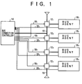
- Fig. 1 is a block diagram showing a bus controller according to a first embodiment of the present invention.
- a plurality of bus connectors 12 1 -12 4 are provided in a bus 10.
- the bus 10 is connected to a bus connection controller 14.
- Bus agents 16 1 -16 4 are connected to the bus connectors 12 1 -12 4 , respectively.
- the number of bus agents connected to the bus connectors 12 1 -12 4 may vary. Only the bus agents that are necessary may be connected to the respective bus connectors.
- the bus agents 16 1 -16 4 input and output information via the bus 10.
- the bus agents 16 1 -16 4 may be a hard disk drive, a flexible disk drive, a modem and the like.
- the bus connectors 12 1 -12 4 are connected to the bus connection controller 14 via control lines 18 1 -18 4 , respectively.
- the bus connection controller 14 supplies a bus agent connection signal or a bus agent disconnection signal to the bus connectors 12 1 -12 4 .
- the bus agents 16 1 -16 4 connected to the bus connectors 12 1 -12 4 , respectively, are also connected to the bus connection controller 14 via control lines 20 1 -20 4 , respectively.
- Each of the bus agents 16 1 -16 4 supplies a request signal requesting the use of the bus 10 to the bus connection controller 14.
- the bus connection controller 14 supplies a bus agent connection signal to the bus connector to which the requesting bus agent is connected so as to control the bus connector to connect the requesting bus agent to the bus 10.
- the bus connection controller 14 also monitors the bus 10. When the bus agent connected to the bus 10 is not involved in an access to the bus 10 for a predetermined period of time, the bus connection controller 14 supplies a bus agent disconnection signal to the associated bus connector so as to control the bus connector to disconnect the associated bus agent from the bus 10.
- the bus agent connection signal is supplied to the bus connector to which the requesting bus agent is connected so that the requesting bus agent is connected to the bus 10.
- the bus agent disconnection signal is supplied to the associated bus connector so that the bus agent is disconnected from the bus 10.
- Fig. 2 is a block diagram of the bus connectors 12 1 -12 4 according to the first embodiment.
- the bus connector 12 1 will be described as an example.
- the bus connector is composed of a switch 22 and a dummy load 24.
- the switch 22 selects one of the bus agent 16 1 and a dummy load 24 so as to connect the selected element to the bus 10. Selection is made depending on whether the bus agent connection signal or the bus agent disconnection signal is supplied by the bus connection controller 14 to the switch 22 via the control line 18 1 .
- the bus agent 16 1 is selected.
- the dummy load 24 is selected.
- the dummy load 24 has substantially the same impedance as the bus agent 16 1 . It is assumed that each of the bus agents 16 2 -16 4 has substantially the same impedance as the bus agent 16 1 .
- the load imposed on the driver (also provided in each of the bus agents) for driving the bus is maintained at a constant level even when the number of bus agents connected to the bus varies.
- the operation is stabilized even in the bus with a severe requirement for electrical performance.
- Fig. 3 is a block diagram showing the bus controller according to a second embodiment of the present invention.
- the plurality of bus connectors 12 1 -12 4 are provided in the bus 10.
- the bus 10 is connected to the bus connection controller 14.
- the bus agents 16 1 -16 4 are connected to the bus connectors 12 1 -12 4 , respectively.
- the number of bus agents connected to the bus connectors 12 1 -12 4 may vary. Only the bus agents that are necessary may be connected to the respective bus connectors.
- the bus agents 16 1 -16 4 input and output information via the bus 10.
- the bus agents 16 1 -16 4 may be a hard disk drive, a flexible disk drive, a modem and the like.
- the bus connectors 12 1 -12 4 are connected to the bus connection controller 14 via the control lines 18 1 -18 4 , respectively.
- the bus connection controller 14 supplies a bus agent connection signal or a bus agent disconnection signal to the bus connectors 12 1 -12 4 .
- the bus agents 16 1 -16 4 connected to the bus connectors 12 1 -12 4 , respectively, are also connected to the bus connection controller 14 via the control lines 20 1 -20 4 , respectively.
- Each of the bus agents 16 1 -16 4 supplies a request signal requesting the use of the bus 10 to the bus connection controller 14.
- a clock controller 30 is supplied with the bus agent connection signal or the bus agent disconnection signal from the bus connection controller 14 via the control lines 18 1 -18 4 .
- a clock signal generated by the clock controller 30 is supplied to the bus agents 16 1 -16 4 via clock lines 32 1 -32 4 , respectively.
- the bus connection controller 14 supplies a bus agent connection signal to the bus connector to which the requesting bus agent is connected so as to control the bus connector to connect the requesting bus agent to the bus 10.
- the clock controller 30 supplied with the bus agent connection signal supplies the clock signal to the bus agent connected to the bus 10.
- the bus connection controller 14 also monitors the bus 10. When the bus agent connected to the bus 10 is not involved in an access to the bus 10 for a predetermined period of time, the bus connection controller 14 supplies a bus agent disconnection signal to the associated bus connector so as to control the bus connector to disconnect the associated bus agent from the bus 10.
- the clock controller 30 supplied with the bus agent disconnection signal reduces a frequency of the clock signal supplied to the bus agent disconnected from the bus 10 or stops supplying the clock signal thereto.
- the bus agent connection signal is supplied to the bus connector to which the requesting bus agent is connected so that the requesting bus agent is connected to the bus 10 and the clock signal is supplied to the requesting bus agent.
- the bus agent disconnection signal is supplied to the associated bus connector so that the bus agent is disconnected from the bus 10 and the frequency of the clock signal supplied to the disconnected bus agent is reduced or the clock signal ceases to be supplied thereto.
- Fig. 4 is a block diagram showing the bus controller according to a third embodiment of the present invention.
- the plurality of bus connectors 12 1 -12 4 are provided in the bus 10.
- the bus 10 is connected to the bus connection controller 14.
- the bus agents 16 1 -16 4 are connected to the bus connectors 12 1 -12 4 , respectively.
- the number of bus agents connected to the bus connectors 12 1 -12 4 may vary. Only the bus agents that are necessary may be connected to the respective bus connectors.
- the bus agents 16 1 -16 4 input and output information via the bus 10.
- the bus agents 16 1 -16 4 may be a hard disk drive, a flexible disk drive, a modem and the like.
- the bus connectors 12 1 -12 4 are connected to the bus connection controller 14 via the control lines 18 1 -18 4 , respectively.
- the bus connection controller 14 supplies a bus agent connection signal or a bus agent disconnection signal to the bus connectors 12 1 -12 4 .
- the bus agents 16 1 -16 4 connected to the bus connectors 12 1 -12 4 , respectively, are also connected to the bus connection controller 14 via the control lines 20 1 -20 4 , respectively.
- Each of the bus agents 16 1 -16 4 supplies a request signal requesting the use of the bus 10 to the bus connection controller 14.
- a power supply voltage controller 36 is supplied with the bus agent connection signal or the bus agent disconnection signal from the bus connection controller 14 via the control lines 18 1 -18 4 .
- a power supply voltage V cc generated by the power supply voltage controller 36 is supplied to the bus agents 16 1 -16 4 via power lines 34 1 -34 4 , respectively.
- the bus connection controller 14 supplies a bus agent connection signal to the bus connector to which the requesting bus agent is connected so as to control the bus connector to connect the requesting bus agent to the bus 10.
- the power supply voltage controller 36 supplied with the bus agent connection signal supplies the power supply voltage V cc to the bus agent connected to the bus 10.
- the bus connection controller 14 also monitors the bus 10. When the bus agent connected to the bus 10 is not involved in an access to the bus 10 for a predetermined period of time, the bus connection controller 14 supplies a bus agent disconnection signal to the associated bus connector and the power supply voltage controller 36 so as to control the bus connector to disconnect the associated bus agent from the bus 10.
- the power supply voltage controller 36 supplied with the bus agent disconnection signal reduces a level of the power supply voltage supplied to the bus agent disconnected from the bus 10 or stops supplying the power supply voltage thereto.
- the bus agent connection signal is supplied to the bus connector to which the requesting bus agent is connected so that the requesting bus agent is connected to the bus 10 and the power supply voltage V cc is supplied to the requesting bus agent.
- the bus agent disconnection signal is supplied to the associated bus connector so that the bus agent is disconnected from the bus 10 and the level of the power supply voltage supplied to the disconnected bus agent is reduced or the power supply voltage ceases to be supplied thereto.
- Fig. 5 is a block diagram showing the bus controller according to a fourth embodiment of the present invention.
- the plurality of bus connectors 12 1 -12 4 are provided in the bus 10.
- the bus 10 is connected to the bus connection controller 14.
- the bus agents 16 1 -16 4 are connected to the bus connectors 12 1 -12 4 , respectively.
- the number of bus agents connected to the bus connectors 12 1 -12 4 may vary. Only the bus agents that are necessary may be connected to the respective bus connectors.
- the bus agents 16 1 -16 4 input and output information via the bus 10.
- the bus agents 16 1 -16 4 may be a hard disk drive, a flexible disk drive, a modem and the like.
- the bus connectors 12 1 -12 4 and the bus agents 16 1 -16 n are connected to the bus connection controller 14 via the control lines 18 1 -18 4 , respectively.
- the bus connection controller 14 supplies a bus agent connection signal or a bus agent disconnection signal to the bus connectors 12 1 -12 4 and the bus agents 16 1 -16 4 .
- the bus agents 16 1 -16 4 connected to the bus connectors 12 1 -12 4 , respectively, are also connected to the bus connection controller 14 via the control lines 20 1 -20 4 , respectively.
- Each of the bus agents 16 1 -16 4 supplies a request signal requesting the use of the bus 10 to the bus connection controller 14.
- the bus connection controller 14 supplies a bus agent connection signal to the bus connector to which the requesting bus agent is connected so as to control the bus connector to connect the requesting bus agent to the bus 10.
- the bus agent connection signal is also supplied to the associated bus agent.
- the bus agent supplied with the bus agent connection signal enhances the external load driving performance of a bus driver built into the bus agent so that the bus driver can drive the bus 10 properly.
- the bus connection controller 14 also monitors the bus 10. When the bus agent connected to the bus 10 is not involved in an access to the bus 10 for a predetermined period of time, the bus connection controller 14 supplies a bus agent disconnection signal to the associated bus connector and the associated bus agent so as to control the bus connector to disconnect the associated bus agent from the bus 10.
- the electrical load on the bus 10 is maintained at a constant level by a simulated means of lowering the external load driving performance of the bus driver built into the bus agent supplied with the bus agent disconnection signal.
- the bus agent connection signal is supplied to the bus connector to which the requesting bus agent is connected so that the requesting bus agent is connected to the bus 10 and the bus driver built into the bus agent is controlled to provide the sufficient performance for driving the bus 10.
- the bus agent disconnection signal is supplied to the associated bus connector so that the associated bus agent is disconnected from the bus 10 and the overall electrical load on the bus 10 is maintained at a constant level by a simulated means of lowering the external load driving performance of the bus driver built into the disconnected bus agent.
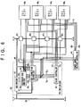
- Fig. 6 is a block diagram showing the bus controller according to a fifth embodiment of the present invention, adapted for a peripheral component interface (PCI) bus.
- PCI peripheral component interface
- a plurality of bus connectors 42 1 -42 4 are provided in a PCI bus 40.
- the PCI bus 40 is connected to a PCI bus bridge unit 52 and a bus connection controller 54 in a PCI bus bridge 50.
- PCI slots 46 1 -46 4 are connected to the bus connectors 42 1 -42 4 , respectively.
- a bus agent in the form of an addin card is inserted into one of PCI slots 46 1 -46 4 .
- the number of bus agents connected to the respective PCI slots may vary. Only the bus agents that are necessary may be connected to the respective PCI slots.
- the bus agents input and output information via the PCI bus 40.
- the bus agents may be a hard disk drive, a flexible disk drive, a modem and the like.
- the PCI bus bridge 50 is a circuit for connecting between the PCI bus 40 to which the bus agents are connected, and a host bus 60 to which a CPU, a RAM, a ROM and the like are connected.
- the PCI bus bridge 50 includes the bus bridge unit 52, the bus connection controller 54, a secondary bus arbiter 56 and a clock controller 58.
- the bus bridge unit 52 is a main unit providing a bridge connection between the PCI bus 40 and the host bus 60.
- the secondary bus arbiter 56 is connected to the PCI slots 46 1 -46 4 via control lines 62 1 -62 4 , respectively, and is also connected to the bus bridge unit 52 via a control line 62 5 .
- the secondary bus arbiter 56 arbitrates between the bus bridge unit 52 and the bus agent by examining the priority pre-assigned to the requesting bus agent and supplying a signal GNT# identifying the bus agent or the bus bridge unit 52 to which a right to use the bus is granted, to the bus connection controller 54 via a relevant one of the control lines 64 1 -64 4 .
- the bus connection controller 54 is connected to the PCI bus 40.
- the request signal is supplied from the PCI slots 46 1 -46 4 to the bus connection controller 54 via the control lines 62 1 -62 4 , respectively.
- the bus connection controller 54 is also supplied by the secondary bus arbiter 56 with the signal GNT# via the control lines 64 1 -64 4 .
- the bus connection controller 54 is connected to the host bus 60 and supplies a retry request signal to the bus bridge unit 52 via a control line 66. The retry signal is sent to the host bus 60 via the bus bridge 52 when the host bus 60 tries to access a disconnected bus agent.
- the bus connection controller 54 supplies the signal GNT#, for granting a right to use the PCI bus 40, to an associated one of the PCI slots 46 1 -46 4 via control lines 68 1 -68 4 , respectively (see Fig. 7).
- the bus connection controller 54 also supplies the bus agent connection signal or the bus agent disconnection signal to an associated one of the bus connectors 42 1 -42 4 , the clock controller 58 and a power supply voltage controller 48.
- the power supply voltage controller 48 supplies a power supply voltage V cc only to the PCI slot supplied with the bus agent connection signal, via an associated one of power lines 49 1 -49 4 .
- the clock controller 58 supplies a clock signal only to the bus PCI slot supplied with the bus agent connection signal, via an associated one of clock lines 72 1 -72 4 .
- Fig. 7 is a block diagram showing the bus connection controller 54 according to the fifth embodiment. In Fig. 7, those elements that are identical to the corresponding elements of Fig. 6 are designated by the same reference numerals.
- a request monitor unit 80 monitors the request signal (requesting the use of the PCI bus 40) supplied from the bus agent connected to a respective one of the PCI slots 46 1 -46 4 via the control lines 62 1 -62 4 , respectively.
- the request monitor unit 80 If it is determined that a time-out beyond a predetermined period of time occurs by referring to a timer 81 for measuring lapsed time for each PCI slot (bus agent), the request monitor unit 80 asserts a master disconnection enable signal (instruction for disconnecting the bus agent) supplied to a connection controller 82 so as to disconnect an associated bus agent.
- a master disconnection enable signal instruction for disconnecting the bus agent
- the request monitor unit 80 also monitors the signal GNT# via the control lines 64 1 -64 5 .
- the request monitor unit 80 masks (cancels) that signal GNT# and supplies the masked signal to the PCI slots 46 1 -46 4 via the control lines 68 1 -68 4 , respectively. Granting a right to use the bus to the disconnected bus agent is improper in that the PCI bus 40 becomes unavailable unless the masking is performed. A grant of a right to use the bus should be supplied to the disconnected bus agent after that bus agent is connected.
- a bus monitor unit 84 monitors the host bus 60 and the PCI bus 40.
- the address space available for the bus agent connected to the PCI bus 40 is assigned to each of the bus agents.
- the assigned address space is stored in an address register unit 86.
- the address space stored in the address register unit 86 is compared with the address monitored to occur on the PCI bus 40.
- a timer 85 is coupled to the bus monitor unit 84 so as to measure an access interval for each PCI slot (bus agent). When it is determined that a time-out beyond a predetermined period of time occurs by referring to the timer 85, the bus monitor unit 84 asserts a target disconnection enable signal (instruction to disconnect the bus agent) supplied to the connection controller 82 so as to disconnect an associated bus agent.
- the bus monitor unit 84 compares the address space stored in the address register unit 86 with the address monitored to occur on the host bus 60. When the address that occurs on the host bus 60 indicates an access to the disconnected bus agent, the bus monitor unit 84 asserts a retry request signal supplied to the bus bridge unit 52 via the control line 66. In addition, the bus monitor unit 84 deasserts a target disconnection enable signal for the disconnected bus agent so as to request the connection controller 82 to perform reconnection. Such an arrangement is necessary in order to access the target bus agent again after the bus agent is connected.
- the bus monitor unit 84 compares the address space stored in the address register unit 86 with the address monitored to occur on the PCI bus 40.
- the bus monitor unit 84 detects an access to the bus agent disconnected in response to the bus agent disconnection signal, delivered on control lines 70 1 -70 4 , the bus monitor unit 84 asserts the dummy target enable signal supplied to a dummy target unit 88 so that the dummy target unit 88 returns a retry request signal to the bus agent to be accessed. Further, the bus monitor unit 84 deasserts the target disconnection enable signal for that bus agent so as to demand cancellation of the disconnection and request the connection controller 82 to perform reconnection. Such an arrangement is necessary in order to access the target bus agent again after the bus agent is connected.
- Fig. 8 shows a circuit configuration of the bus connectors 42 1 -42 4 according to the fifth embodiment.
- the bus connector 42 1 will be described as an example. In Fig. 8, those components that are identical to the corresponding components of Fig. 6 are designated by the same reference numerals.
- a terminal 90 is connected to the PCI bus 40, and a terminal 92 is connected to the PCI slot 46 1 .
- An analog switch 94 is connected between the terminals 90 and 92.
- the terminal 92 is connected to a power supply (voltage V cc ) via an analog switch 96 and a pull-up resistor R1.
- the terminal 90 is grounded via an analog switch 98 and a dummy load C D .
- a terminal 100 is connected to the control line 70 1 .
- the bus agent connection signal and the bus agent disconnection signal supplied via the control line 70 1 is supplied to a positive control terminal of the analog switch 94, and to negative control terminals of the analog switches 96 and 98.
- the bus agent connection signal and the bus agent disconnection signal are inverted by an inverter 102 and supplied to a positive control terminal of the analog switches 96 and 98, and to a negative control terminal of the analog switch 94.
- the analog switch 94 When the terminal 100 is at a high level, indicating that the bus agent is to be connected to the PCI bus 40, the analog switch 94 is closed and the analog switches 96 and 98 are open so that connection is established between the PCI bus 40 and the PCI slot 46 1 .
- the analog switches 96 and 98 are closed and the analog switch 94 is open so that the PCI bus 40 is disconnected from the PCI slot 46 1 . With this, the PCI slot 46 1 is pulled up to the voltage V cc and the PCI bus 40 is terminated with the dummy load C D .
Abstract
A bus controller includes a plurality of bus
connectors (121-124) provided in a bus (10) so as to
respectively connect a plurality of bus agents
(161-164) from the bus (10); and a bus connection
controller (14) for monitoring the bus (10) and for
controlling the plurality of bus connectors (121-124)
so as to disconnect the bus agent not accessed for a
predetermined period of time.
Description
- The present invention generally relates to bus controllers and, more particularly, to a bus controller for controlling connection of bus agents to a bus.
- Recently, as the operating speed of computer systems is improved, a demand for a high-speed bus inside a system is growing. In order to facilitate improvement in the speed of a bus, the standards impose a severe requirement for electrical performance on a bus. In order to insure a stable operation in the bus constructed under the severe requirement, the electrical characteristic of the bus should be stabilized.
- Conventionally, a bus is provided with a plurality of connectors so that a bus agent in the form of an add-in card is connected to each of the connectors. The number of bus agents connected to the bus is variable. No bus controller for managing the bus agents connected to the bus is provided. Each of the bus agents connected to the bus continually decodes an address delivered on the bus so as to determine whether an access to the bus agent occurs.
- The load imposed on a driver (also provided in each of the bus agents) for driving the bus varies depending on the number of bus agents connected to the bus. For this reason, the operation of the bus with a severe requirement for electrical performance may be unstable.
- Since the bus agents are operated such that even those bus agents connected to the bus but not accessed for a long period of time decode an address delivered on the bus, there is a problem in that an unnecessarily large power consumption may result.
- Accordingly, a general object of the present invention is to provide a bus controller in which the aforementioned problems are eliminated.
- Another and more specific object is to provide a bus controller in which the operation of unnecessary bus agents is stopped so that the overall power consumption is reduced.
- The aforementioned objects can be achieved by a bus controller for controlling connection of a plurality of bus agents to a bus, comprising a plurality of bus connectors provided in the bus so as to respectively connect the plurality of bus agents to the bus and to respectively disconnect the plurality of bus agents from the bus; and
- a bus connection controller for monitoring the bus and for controlling the plurality of bus connectors so as to disconnect the bus agent not accessed for a predetermined period of time.
-
- According to the bus controller of the present invention, the bus agent not accessed for a predetermined period of time and disconnected from the bus does not decode an address supplied via the bus. In this way, the power consumption is reduced.
- Each of the bus connectors may have a switch for selectively connecting one of the bus agent and a dummy load to the bus such that the dummy load is connected to the bus when the bus agent is disconnected from the bus.
- According to this aspect of the invention, the overall electrical load on the bus is maintained at a constant level so that the stable operation of the bus is achieved.
- The bus controller may further comprise a clock controller for supplying a clock signal to each of the bus agents. The bus connection controller may control the clock controller to one of reduce a frequency of the clock signal supplied to the bus agent disconnected from the bus and stop supplying the clock signal to the bus agent disconnected from the bus.
- According to this aspect of the invention, the power consumption in the disconnected bus agent is reduced.
- The bus controller may further comprise a power supply voltage controller for supplying a power supply voltage to each of the bus agents, and the bus connection controller may control the power supply voltage controller to one of reduce a level of voltage supplied to the bus agent disconnected from the bus and stop supplying the power supply voltage to the bus agent disconnected from the bus.
- According to this aspect of the invention, the power consumption in the disconnected bus agent is reduced.
- The bus connection controller may reduce an external load driving performance of the bus agent disconnected from the bus.
- According to this aspect of the invention, the overall electrical load on the bus is maintained at a constant level by a simulated means of reducing the external load driving performance of the bus agent.
- The bus may be a PCI bus, the bus controller may be adapted for a bus bridge for connecting the PCI bus and a host bus, and the bus connection controller may comprise: a request monitor unit for monitoring a request from each of the plurality of bus agents to use the PCI bus and disconnecting the bus agent not issuing the request for a predetermined period of time from the bus; and a bus monitor unit for monitoring an address supplied from the PCI bus and the host bus to each of the plurality of bus agents and for disconnecting the bus agent not accessed for a predetermined period of time from the PCI bus.
- According to this aspect of the invention, the bus agent not accessed for a predetermined period of time is disconnected from the PCI bus and the bus agent not issuing a request to use the PCI bus for a predetermined period of time is disconnected from the PCI bus.
- The bus monitor unit may monitor a signal for controlling each of the plurality of bus connectors and a signal for granting a right to use the PCI bus, and cancel a grant of the right to use the PCI bus when the grant is issued to the disconnected bus agent.
- According to this aspect of the invention, a grant of a right to use the bus is prevented from being supplied to the disconnected bus agent, thus preventing the PCI bus from becoming unavailable.
- The bus monitor unit may monitor a signal for controlling each of the plurality of bus connectors, and, when an access to the disconnected agent is detected, request a retry of the access and cancel the disconnection.
- According to this aspect of the invention, when an access to the disconnected bus agent can occur for a second time after the requested bus agent is connected to the PCI bus again.
- Other objects and further features of the present invention will be apparent from the following detailed description when read in conjunction with the accompanying drawings, in which:
- Fig. 1 is a block diagram showing a bus controller according to a first embodiment of the present invention;
- Fig. 2 is a block diagram of the bus connectors according to the first embodiment;
- Fig. 3 is a block diagram of the bus controller according to a second embodiment of the present invention;
- Fig. 4 is a block diagram of the bus controller according to a third embodiment of the present invention;
- Fig. 5 is a block diagram of the bus controller according to a fourth embodiment of the present invention;
- Fig. 6 is a block diagram of the bus controller according to a fifth embodiment of the present invention, adapted for a PCI bus;
- Fig. 7 is a block diagram showing the bus connection controller according to the fifth embodiment; and
- Fig. 8 shows a circuit configuration of the bus connectors according to the fifth embodiment.
-
- Fig. 1 is a block diagram showing a bus controller according to a first embodiment of the present invention. A plurality of bus connectors 121-124 are provided in a
bus 10. Thebus 10 is connected to abus connection controller 14. Bus agents 161-164 are connected to the bus connectors 121-124, respectively. Of course, the number of bus agents connected to the bus connectors 121-124 may vary. Only the bus agents that are necessary may be connected to the respective bus connectors. The bus agents 161-164 input and output information via thebus 10. For example, the bus agents 161-164 may be a hard disk drive, a flexible disk drive, a modem and the like. - The bus connectors 121-124 are connected to the
bus connection controller 14 via control lines 181-184, respectively. Thebus connection controller 14 supplies a bus agent connection signal or a bus agent disconnection signal to the bus connectors 121-124. The bus agents 161-164 connected to the bus connectors 121-124, respectively, are also connected to thebus connection controller 14 via control lines 201-204, respectively. Each of the bus agents 161-164 supplies a request signal requesting the use of thebus 10 to thebus connection controller 14. - When the request signal is supplied by any of the bus agents 161-164, the
bus connection controller 14 supplies a bus agent connection signal to the bus connector to which the requesting bus agent is connected so as to control the bus connector to connect the requesting bus agent to thebus 10. Thebus connection controller 14 also monitors thebus 10. When the bus agent connected to thebus 10 is not involved in an access to thebus 10 for a predetermined period of time, thebus connection controller 14 supplies a bus agent disconnection signal to the associated bus connector so as to control the bus connector to disconnect the associated bus agent from thebus 10. - Thus, when the request signal is supplied by any of the bus agents 161-164, the bus agent connection signal is supplied to the bus connector to which the requesting bus agent is connected so that the requesting bus agent is connected to the
bus 10. When the bus agent connected to thebus 10 is not involved in an access for a predetermined period of time, the bus agent disconnection signal is supplied to the associated bus connector so that the bus agent is disconnected from thebus 10. With this arrangement, thebus connection controller 14 can control connection of the bus agents 161-164 to thebus 10. Since the bus agent disconnected from thebus 10 is not supplied with addresses from thebus 10, it is not necessary for the bus agent to decode an address. Accordingly, the power consumption is reduced. - Fig. 2 is a block diagram of the bus connectors 121-124 according to the first embodiment. The bus connector 121 will be described as an example. Referring to Fig. 2, the bus connector is composed of a
switch 22 and a dummy load 24. Theswitch 22 selects one of the bus agent 161 and a dummy load 24 so as to connect the selected element to thebus 10. Selection is made depending on whether the bus agent connection signal or the bus agent disconnection signal is supplied by thebus connection controller 14 to theswitch 22 via the control line 181. When the bus agent connection signal is supplied, the bus agent 161 is selected. When the bus agent disconnection signal is supplied, the dummy load 24 is selected. The dummy load 24 has substantially the same impedance as the bus agent 161. It is assumed that each of the bus agents 162-164 has substantially the same impedance as the bus agent 161. - Since one of the bus agent 161 and the dummy load 24 having substantially the identical impedance is connected to the
bus 10, the load imposed on the driver (also provided in each of the bus agents) for driving the bus is maintained at a constant level even when the number of bus agents connected to the bus varies. Thus, the operation is stabilized even in the bus with a severe requirement for electrical performance. - Fig. 3 is a block diagram showing the bus controller according to a second embodiment of the present invention. In Fig. 3, those elements that are identical to the corresponding elements of Fig. 1 are designated by the same reference numerals. The plurality of bus connectors 121-124 are provided in the
bus 10. Thebus 10 is connected to thebus connection controller 14. The bus agents 161-164 are connected to the bus connectors 121-124, respectively. Of course, the number of bus agents connected to the bus connectors 121-124 may vary. Only the bus agents that are necessary may be connected to the respective bus connectors. The bus agents 161-164 input and output information via thebus 10. For example, the bus agents 161-164 may be a hard disk drive, a flexible disk drive, a modem and the like. - The bus connectors 121-124 are connected to the
bus connection controller 14 via the control lines 181-184, respectively. Thebus connection controller 14 supplies a bus agent connection signal or a bus agent disconnection signal to the bus connectors 121-124. The bus agents 161-164 connected to the bus connectors 121-124, respectively, are also connected to thebus connection controller 14 via the control lines 201-204, respectively. Each of the bus agents 161-164 supplies a request signal requesting the use of thebus 10 to thebus connection controller 14. - A
clock controller 30 is supplied with the bus agent connection signal or the bus agent disconnection signal from thebus connection controller 14 via the control lines 181-184. A clock signal generated by theclock controller 30 is supplied to the bus agents 161-164 via clock lines 321-324, respectively. - When the request signal is supplied by any of the bus agents 161-164, the
bus connection controller 14 supplies a bus agent connection signal to the bus connector to which the requesting bus agent is connected so as to control the bus connector to connect the requesting bus agent to thebus 10. Theclock controller 30 supplied with the bus agent connection signal supplies the clock signal to the bus agent connected to thebus 10. - The
bus connection controller 14 also monitors thebus 10. When the bus agent connected to thebus 10 is not involved in an access to thebus 10 for a predetermined period of time, thebus connection controller 14 supplies a bus agent disconnection signal to the associated bus connector so as to control the bus connector to disconnect the associated bus agent from thebus 10. Theclock controller 30 supplied with the bus agent disconnection signal reduces a frequency of the clock signal supplied to the bus agent disconnected from thebus 10 or stops supplying the clock signal thereto. - Thus, when the request signal is supplied by any of the bus agents 161-164, the bus agent connection signal is supplied to the bus connector to which the requesting bus agent is connected so that the requesting bus agent is connected to the
bus 10 and the clock signal is supplied to the requesting bus agent. When the bus agent connected to thebus 10 is not involved in an access for a predetermined period of time, the bus agent disconnection signal is supplied to the associated bus connector so that the bus agent is disconnected from thebus 10 and the frequency of the clock signal supplied to the disconnected bus agent is reduced or the clock signal ceases to be supplied thereto. With this arrangement, the operation of the bus agent disconnected from the bus is stopped or slowed down. Accordingly, the power consumption is reduced. - Fig. 4 is a block diagram showing the bus controller according to a third embodiment of the present invention. In Fig. 4, those elements that are identical to the corresponding elements of Fig. 1 are designated by the same reference numerals. The plurality of bus connectors 121-124 are provided in the
bus 10. Thebus 10 is connected to thebus connection controller 14. The bus agents 161-164 are connected to the bus connectors 121-124, respectively. Of course, the number of bus agents connected to the bus connectors 121-124 may vary. Only the bus agents that are necessary may be connected to the respective bus connectors. The bus agents 161-164 input and output information via thebus 10. For example, the bus agents 161-164 may be a hard disk drive, a flexible disk drive, a modem and the like. - The bus connectors 121-124 are connected to the
bus connection controller 14 via the control lines 181-184, respectively. Thebus connection controller 14 supplies a bus agent connection signal or a bus agent disconnection signal to the bus connectors 121-124. The bus agents 161-164 connected to the bus connectors 121-124, respectively, are also connected to thebus connection controller 14 via the control lines 201-204, respectively. Each of the bus agents 161-164 supplies a request signal requesting the use of thebus 10 to thebus connection controller 14. - A power
supply voltage controller 36 is supplied with the bus agent connection signal or the bus agent disconnection signal from thebus connection controller 14 via the control lines 181-184. A power supply voltage Vcc generated by the powersupply voltage controller 36 is supplied to the bus agents 161-164 via power lines 341-344, respectively. - When the request signal is supplied by any of the bus agents 161-164, the
bus connection controller 14 supplies a bus agent connection signal to the bus connector to which the requesting bus agent is connected so as to control the bus connector to connect the requesting bus agent to thebus 10. The powersupply voltage controller 36 supplied with the bus agent connection signal supplies the power supply voltage Vcc to the bus agent connected to thebus 10. - The
bus connection controller 14 also monitors thebus 10. When the bus agent connected to thebus 10 is not involved in an access to thebus 10 for a predetermined period of time, thebus connection controller 14 supplies a bus agent disconnection signal to the associated bus connector and the powersupply voltage controller 36 so as to control the bus connector to disconnect the associated bus agent from thebus 10. The powersupply voltage controller 36 supplied with the bus agent disconnection signal reduces a level of the power supply voltage supplied to the bus agent disconnected from thebus 10 or stops supplying the power supply voltage thereto. - Thus, when the request signal is supplied by any of the bus agents 161-164, the bus agent connection signal is supplied to the bus connector to which the requesting bus agent is connected so that the requesting bus agent is connected to the
bus 10 and the power supply voltage Vcc is supplied to the requesting bus agent. When the bus agent connected to thebus 10 is not involved in an access for a predetermined period of time, the bus agent disconnection signal is supplied to the associated bus connector so that the bus agent is disconnected from thebus 10 and the level of the power supply voltage supplied to the disconnected bus agent is reduced or the power supply voltage ceases to be supplied thereto. With this arrangement, the operation of the bus agent disconnected from the bus is stopped or slowed down. Accordingly, the power consumption is reduced. - Fig. 5 is a block diagram showing the bus controller according to a fourth embodiment of the present invention. In Fig. 5, those elements that are identical to the corresponding elements of Fig. 1 are designated by the same reference numerals. The plurality of bus connectors 121-124 are provided in the
bus 10. Thebus 10 is connected to thebus connection controller 14. The bus agents 161-164 are connected to the bus connectors 121-124, respectively. Of course, the number of bus agents connected to the bus connectors 121-124 may vary. Only the bus agents that are necessary may be connected to the respective bus connectors. The bus agents 161-164 input and output information via thebus 10. For example, the bus agents 161-164 may be a hard disk drive, a flexible disk drive, a modem and the like. - The bus connectors 121-124 and the bus agents 161-16n are connected to the
bus connection controller 14 via the control lines 181-184, respectively. Thebus connection controller 14 supplies a bus agent connection signal or a bus agent disconnection signal to the bus connectors 121-124 and the bus agents 161-164. The bus agents 161-164 connected to the bus connectors 121-124, respectively, are also connected to thebus connection controller 14 via the control lines 201-204, respectively. Each of the bus agents 161-164 supplies a request signal requesting the use of thebus 10 to thebus connection controller 14. - When the request signal is supplied by any of the bus agents 161-164, the
bus connection controller 14 supplies a bus agent connection signal to the bus connector to which the requesting bus agent is connected so as to control the bus connector to connect the requesting bus agent to thebus 10. The bus agent connection signal is also supplied to the associated bus agent. The bus agent supplied with the bus agent connection signal enhances the external load driving performance of a bus driver built into the bus agent so that the bus driver can drive thebus 10 properly. - The
bus connection controller 14 also monitors thebus 10. When the bus agent connected to thebus 10 is not involved in an access to thebus 10 for a predetermined period of time, thebus connection controller 14 supplies a bus agent disconnection signal to the associated bus connector and the associated bus agent so as to control the bus connector to disconnect the associated bus agent from thebus 10. The electrical load on thebus 10 is maintained at a constant level by a simulated means of lowering the external load driving performance of the bus driver built into the bus agent supplied with the bus agent disconnection signal. - Thus, when the request signal is supplied by any of the bus agents 161-164, the bus agent connection signal is supplied to the bus connector to which the requesting bus agent is connected so that the requesting bus agent is connected to the
bus 10 and the bus driver built into the bus agent is controlled to provide the sufficient performance for driving thebus 10. When the bus agent connected to thebus 10 is not involved in an access for a predetermined period of time, the bus agent disconnection signal is supplied to the associated bus connector so that the associated bus agent is disconnected from thebus 10 and the overall electrical load on thebus 10 is maintained at a constant level by a simulated means of lowering the external load driving performance of the bus driver built into the disconnected bus agent. With this arrangement, the stable operation is insured even in a bus with a severe requirement for electrical performance, and the power consumption of the bus driver built into the disconnected bus agent is reduced. - Fig. 6 is a block diagram showing the bus controller according to a fifth embodiment of the present invention, adapted for a peripheral component interface (PCI) bus. A plurality of bus connectors 421-424 are provided in a
PCI bus 40. ThePCI bus 40 is connected to a PCIbus bridge unit 52 and abus connection controller 54 in aPCI bus bridge 50. PCI slots 461-464 are connected to the bus connectors 421-424, respectively. A bus agent in the form of an addin card is inserted into one of PCI slots 461-464. Of course, the number of bus agents connected to the respective PCI slots may vary. Only the bus agents that are necessary may be connected to the respective PCI slots. The bus agents input and output information via thePCI bus 40. For example, the bus agents may be a hard disk drive, a flexible disk drive, a modem and the like. - The
PCI bus bridge 50 is a circuit for connecting between thePCI bus 40 to which the bus agents are connected, and ahost bus 60 to which a CPU, a RAM, a ROM and the like are connected. ThePCI bus bridge 50 includes thebus bridge unit 52, thebus connection controller 54, asecondary bus arbiter 56 and aclock controller 58. Thebus bridge unit 52 is a main unit providing a bridge connection between thePCI bus 40 and thehost bus 60. Thesecondary bus arbiter 56 is connected to the PCI slots 461-464 via control lines 621-624, respectively, and is also connected to thebus bridge unit 52 via a control line 625. When a request signal requesting the use of thePCI bus 40 is issued by thebus bridge unit 52 and the bus agent connected to one of the PCI slots 461-464, thesecondary bus arbiter 56 arbitrates between thebus bridge unit 52 and the bus agent by examining the priority pre-assigned to the requesting bus agent and supplying a signal GNT# identifying the bus agent or thebus bridge unit 52 to which a right to use the bus is granted, to thebus connection controller 54 via a relevant one of the control lines 641-644. - The
bus connection controller 54 is connected to thePCI bus 40. The request signal is supplied from the PCI slots 461-464 to thebus connection controller 54 via the control lines 621-624, respectively. Thebus connection controller 54 is also supplied by thesecondary bus arbiter 56 with the signal GNT# via the control lines 641-644. Thebus connection controller 54 is connected to thehost bus 60 and supplies a retry request signal to thebus bridge unit 52 via acontrol line 66. The retry signal is sent to thehost bus 60 via thebus bridge 52 when thehost bus 60 tries to access a disconnected bus agent. - The
bus connection controller 54 supplies the signal GNT#, for granting a right to use thePCI bus 40, to an associated one of the PCI slots 461-464 via control lines 681-684, respectively (see Fig. 7). Thebus connection controller 54 also supplies the bus agent connection signal or the bus agent disconnection signal to an associated one of the bus connectors 421-424, theclock controller 58 and a powersupply voltage controller 48. The powersupply voltage controller 48 supplies a power supply voltage Vcc only to the PCI slot supplied with the bus agent connection signal, via an associated one of power lines 491-494. Theclock controller 58 supplies a clock signal only to the bus PCI slot supplied with the bus agent connection signal, via an associated one of clock lines 721-724. - Fig. 7 is a block diagram showing the
bus connection controller 54 according to the fifth embodiment. In Fig. 7, those elements that are identical to the corresponding elements of Fig. 6 are designated by the same reference numerals. Arequest monitor unit 80 monitors the request signal (requesting the use of the PCI bus 40) supplied from the bus agent connected to a respective one of the PCI slots 461-464 via the control lines 621-624, respectively. If it is determined that a time-out beyond a predetermined period of time occurs by referring to atimer 81 for measuring lapsed time for each PCI slot (bus agent), therequest monitor unit 80 asserts a master disconnection enable signal (instruction for disconnecting the bus agent) supplied to aconnection controller 82 so as to disconnect an associated bus agent. - The
request monitor unit 80 also monitors the signal GNT# via the control lines 641-645. When the signal GNT# indicating a grant of a right to use thePCI bus 40 to the disconnected bus agent is asserted, therequest monitor unit 80 masks (cancels) that signal GNT# and supplies the masked signal to the PCI slots 461-464 via the control lines 681-684, respectively. Granting a right to use the bus to the disconnected bus agent is improper in that thePCI bus 40 becomes unavailable unless the masking is performed. A grant of a right to use the bus should be supplied to the disconnected bus agent after that bus agent is connected. - A
bus monitor unit 84 monitors thehost bus 60 and thePCI bus 40. When thePCI bus 40 is initialised, the address space available for the bus agent connected to thePCI bus 40 is assigned to each of the bus agents. The assigned address space is stored in anaddress register unit 86. The address space stored in theaddress register unit 86 is compared with the address monitored to occur on thePCI bus 40. Atimer 85 is coupled to thebus monitor unit 84 so as to measure an access interval for each PCI slot (bus agent). When it is determined that a time-out beyond a predetermined period of time occurs by referring to thetimer 85, thebus monitor unit 84 asserts a target disconnection enable signal (instruction to disconnect the bus agent) supplied to theconnection controller 82 so as to disconnect an associated bus agent. - The
bus monitor unit 84 compares the address space stored in theaddress register unit 86 with the address monitored to occur on thehost bus 60. When the address that occurs on thehost bus 60 indicates an access to the disconnected bus agent, thebus monitor unit 84 asserts a retry request signal supplied to thebus bridge unit 52 via thecontrol line 66. In addition, thebus monitor unit 84 deasserts a target disconnection enable signal for the disconnected bus agent so as to request theconnection controller 82 to perform reconnection. Such an arrangement is necessary in order to access the target bus agent again after the bus agent is connected. - The
bus monitor unit 84 compares the address space stored in theaddress register unit 86 with the address monitored to occur on thePCI bus 40. When thebus monitor unit 84 detects an access to the bus agent disconnected in response to the bus agent disconnection signal, delivered on control lines 701-704, thebus monitor unit 84 asserts the dummy target enable signal supplied to a dummy target unit 88 so that the dummy target unit 88 returns a retry request signal to the bus agent to be accessed. Further, thebus monitor unit 84 deasserts the target disconnection enable signal for that bus agent so as to demand cancellation of the disconnection and request theconnection controller 82 to perform reconnection. Such an arrangement is necessary in order to access the target bus agent again after the bus agent is connected. - Fig. 8 shows a circuit configuration of the bus connectors 421-424 according to the fifth embodiment. The bus connector 421 will be described as an example. In Fig. 8, those components that are identical to the corresponding components of Fig. 6 are designated by the same reference numerals. Referring to Fig. 8, a terminal 90 is connected to the
PCI bus 40, and a terminal 92 is connected to the PCI slot 461. Ananalog switch 94 is connected between theterminals analog switch 96 and a pull-up resistor R1. The terminal 90 is grounded via ananalog switch 98 and a dummy load CD. - A terminal 100 is connected to the control line 701. The bus agent connection signal and the bus agent disconnection signal supplied via the control line 701 is supplied to a positive control terminal of the
analog switch 94, and to negative control terminals of the analog switches 96 and 98. The bus agent connection signal and the bus agent disconnection signal are inverted by aninverter 102 and supplied to a positive control terminal of the analog switches 96 and 98, and to a negative control terminal of theanalog switch 94. - When the terminal 100 is at a high level, indicating that the bus agent is to be connected to the
PCI bus 40, theanalog switch 94 is closed and the analog switches 96 and 98 are open so that connection is established between thePCI bus 40 and the PCI slot 461. When the terminal 100 is at a low level, indicating that the bus agent is to be disconnected from thePCI bus 40, the analog switches 96 and 98 are closed and theanalog switch 94 is open so that thePCI bus 40 is disconnected from the PCI slot 461. With this, the PCI slot 461 is pulled up to the voltage Vcc and thePCI bus 40 is terminated with the dummy load CD. - The present invention is not limited to the above-described embodiments, and variations and modifications may be made without departing from the scope of the present invention.
Claims (9)
- A bus controller for controlling connection of a plurality of bus agents (161-164) to a bus (10), comprisinga plurality of bus connectors (121-124) provided in said bus (10) so as to respectively connect said plurality of bus agents (161-164) to said bus (10) and to respectively disconnect said plurality of bus agents (161-164) from said bus (10); anda bus connection controller (14) for monitoring said bus (10) and for controlling said plurality of bus connectors (121-124) so as to disconnect the bus agent not accessed for a predetermined period of time.
- The bus controller as claimed in claim 1, wherein each of said bus connectors (121-124) has a switch (22) for selectively connecting one of the bus agent and a dummy load (24) to said bus (10) such that the dummy load (24) is connected to said bus (10) when the bus agent is disconnected from said bus (10).
- The bus controller as claimed in claim 1, further comprising a clock controller (30) for supplying a clock signal to each of said bus agents (161-164), whereinsaid bus connection controller (14) controls said clock controller (30) to one of reduce a frequency of the clock signal supplied to the bus agent disconnected from said bus (10) and stops supplying the clock signal to the bus agent disconnected from said bus (10).
- The bus controller as claimed in claim 1, further comprising a power supply voltage controller (36) for supplying a power supply voltage to each of said bus agents (161-164), whereinsaid bus connection controller (14) controls said power supply voltage controller (36) to one of reduce a level of voltage supplied to the bus agent disconnected from said bus (10) and stop supplying the power supply voltage to the bus agent disconnected from said bus (10).
- The bus controller as claimed in claim 1, wherein said bus connection controller (14) lowers an external load driving performance of the bus agent disconnected from said bus (10).
- The bus controller as claimed in claim 4, wherein said bus is a PCI bus (40) and said bus controller is adapted for a bus bridge (50) for connecting said PCI bus (40) and a host bus (60).
- The bus controller as claimed in claim 6, wherein said bus connection controller (54) comprises:a request monitor unit (80) for monitoring a request from each of said plurality of bus agents (161-164) to use said PCI bus (40) and disconnecting the bus agent not issuing the request for a predetermined period of time from said bus (40); anda bus monitor unit (84) for monitoring an address supplied from said PCI bus (40) and said host bus (60) to each of said plurality of bus agents (161-164) and for disconnecting the bus agent not accessed for a predetermined period of time from said PCI bus (40).
- The bus controller as claimed in claim 7, wherein said bus monitor unit (84) monitors a signal for controlling each of said plurality of bus connectors (121-124) and a signal for granting a right to use the PCI bus (40), and cancels a grant of the right to use the PCI bus (40) when said grant is issued to the disconnected bus agent.
- The bus controller as claimed in claim 7, wherein said bus monitor unit monitors a signal for controlling each of said plurality of bus connectors (121-124), and, when an access to the disconnected agent is detected, requests a retry of the access and cancels the disconnection.
Applications Claiming Priority (2)
| Application Number | Priority Date | Filing Date | Title |
|---|---|---|---|
| JP10012686A JPH11212687A (en) | 1998-01-26 | 1998-01-26 | Bus controller |
| JP1268698 | 1998-01-26 |
Publications (1)
| Publication Number | Publication Date |
|---|---|
| EP0932097A1 true EP0932097A1 (en) | 1999-07-28 |
Family
ID=11812272
Family Applications (1)
| Application Number | Title | Priority Date | Filing Date |
|---|---|---|---|
| EP98307121A Withdrawn EP0932097A1 (en) | 1998-01-26 | 1998-09-04 | Bus controllers ensuring reduced power consumption and stable operation |
Country Status (5)
| Country | Link |
|---|---|
| US (1) | US6073195A (en) |
| EP (1) | EP0932097A1 (en) |
| JP (1) | JPH11212687A (en) |
| KR (1) | KR100323010B1 (en) |
| TW (1) | TW469378B (en) |
Cited By (4)
| Publication number | Priority date | Publication date | Assignee | Title |
|---|---|---|---|---|
| WO2002059731A2 (en) * | 2000-11-17 | 2002-08-01 | Links Point, Inc. | Methods and systems for reducing power consumption in computer data communications |
| WO2004053705A2 (en) * | 2002-12-11 | 2004-06-24 | Intel Corporation | An apparatus and method for data bus power control |
| US7216240B2 (en) | 2002-12-11 | 2007-05-08 | Intel Corporation | Apparatus and method for address bus power control |
| US8176240B2 (en) | 2002-01-02 | 2012-05-08 | Intel Corporation | Method and apparatus for reducing power consumption in a memory bus interface by selectively disabling and enabling sense amplifiers |
Families Citing this family (25)
| Publication number | Priority date | Publication date | Assignee | Title |
|---|---|---|---|---|
| US6256689B1 (en) * | 1998-06-11 | 2001-07-03 | Adaptec, Inc. | Bus system expandable by connection of a bus bridge circuit |
| JP2000105638A (en) * | 1998-09-29 | 2000-04-11 | Nec Corp | Usb device and usb connection system |
| US7197589B1 (en) * | 1999-05-21 | 2007-03-27 | Silicon Graphics, Inc. | System and method for providing access to a bus |
| JP2002297274A (en) * | 2001-03-30 | 2002-10-11 | Toshiba Corp | Computer system and extended board and connector to be used for the same system |
| JP2009022053A (en) * | 2001-07-27 | 2009-01-29 | Sanyo Electric Co Ltd | Imaging apparatus |
| JP2009017604A (en) * | 2001-08-01 | 2009-01-22 | Sanyo Electric Co Ltd | Image signal processing device |
| US6799226B1 (en) * | 2002-07-23 | 2004-09-28 | Apple Computer, Inc. | Hot unpluggable media storage device |
| US20040128416A1 (en) * | 2002-12-11 | 2004-07-01 | Tsvika Kurts | Apparatus and method for address bus power control |
| JP4371739B2 (en) | 2003-09-02 | 2009-11-25 | 株式会社東芝 | Electronic device having serial ATA interface and power saving method of serial ATA bus |
| KR100618817B1 (en) * | 2003-12-17 | 2006-08-31 | 삼성전자주식회사 | System and method for Advanced Micro-controller Bus ArchitectureAMBA improving power consumption |
| JP4398386B2 (en) * | 2005-01-28 | 2010-01-13 | 富士通株式会社 | Device for interconnecting multiple processing nodes via serial bus |
| US20060207268A1 (en) * | 2005-03-17 | 2006-09-21 | International Business Machines Corporation | System and method for increasing the efficiency of a thermal management profile |
| US7631050B2 (en) * | 2005-10-27 | 2009-12-08 | International Business Machines Corporation | Method for confirming identity of a master node selected to control I/O fabric configuration in a multi-host environment |
| EP1830268B1 (en) * | 2006-03-03 | 2019-05-08 | STMicroelectronics (Research & Development) Limited | Multiple purpose integrated circuit |
| US8405617B2 (en) * | 2007-01-03 | 2013-03-26 | Apple Inc. | Gated power management over a system bus |
| US7730337B2 (en) * | 2007-01-24 | 2010-06-01 | Via Technologies, Inc. | Method and apparatus for asserting a hardware pin to disable a data bus connecting a processor and a chipset during power saving state |
| JP4587000B2 (en) * | 2007-07-02 | 2010-11-24 | 岩崎通信機株式会社 | Chip select circuit |
| TW200928664A (en) | 2007-12-27 | 2009-07-01 | Asustek Comp Inc | Computer system and power-saving method thereof |
| TW200939009A (en) * | 2008-03-06 | 2009-09-16 | Asustek Comp Inc | Power saving system and method |
| JP5244759B2 (en) * | 2009-10-05 | 2013-07-24 | 京セラドキュメントソリューションズ株式会社 | Information processing apparatus and image forming apparatus |
| JP5617429B2 (en) * | 2010-08-19 | 2014-11-05 | ソニー株式会社 | Bridge system for connecting the bus system and the bus system to the connected device |
| US9563841B2 (en) * | 2012-07-31 | 2017-02-07 | International Business Machines Corporation | Globally asynchronous and locally synchronous (GALS) neuromorphic network |
| US9465766B1 (en) * | 2013-10-29 | 2016-10-11 | Xilinx, Inc. | Isolation interface for master-slave communication protocols |
| US9666226B1 (en) | 2015-11-23 | 2017-05-30 | Kabushiki Kaisha Toshiba | Impedance matching for an integrated circuit of a magnetic disk device |
| JP6396352B2 (en) | 2016-03-11 | 2018-09-26 | 株式会社東芝 | Semiconductor device |
Citations (4)
| Publication number | Priority date | Publication date | Assignee | Title |
|---|---|---|---|---|
| JPH02198226A (en) * | 1988-12-26 | 1990-08-06 | Matsushita Electric Ind Co Ltd | Transmitter |
| WO1993007558A1 (en) * | 1991-10-04 | 1993-04-15 | National Research Council Of Canada | Power management system |
| JPH06161619A (en) * | 1992-11-25 | 1994-06-10 | Just Syst Corp | Intermittent controller between bus and electronic equipment |
| US5461266A (en) * | 1990-11-27 | 1995-10-24 | Hitachi, Ltd. | Power consumption control system |
Family Cites Families (6)
| Publication number | Priority date | Publication date | Assignee | Title |
|---|---|---|---|---|
| JPS6285374A (en) * | 1985-10-09 | 1987-04-18 | Nec Corp | Bus coupling device |
| US4980836A (en) * | 1988-10-14 | 1990-12-25 | Compaq Computer Corporation | Apparatus for reducing computer system power consumption |
| JP3034362B2 (en) * | 1990-11-22 | 2000-04-17 | 株式会社日立製作所 | Peripheral controller and SCSI bus controller |
| US5796992A (en) * | 1995-12-20 | 1998-08-18 | Compaq Computer Corporation | Circuit for switching between synchronous and asynchronous memory refresh cycles in low power mode |
| US5884053A (en) * | 1997-06-11 | 1999-03-16 | International Business Machines Corporation | Connector for higher performance PCI with differential signaling |
| US5896514A (en) * | 1997-08-23 | 1999-04-20 | Vlsi Technology, Inc. | Logic implementation of control signals for on-silicon multi-master data transfer bus |
-
1998
- 1998-01-26 JP JP10012686A patent/JPH11212687A/en not_active Withdrawn
- 1998-09-03 US US09/145,965 patent/US6073195A/en not_active Expired - Fee Related
- 1998-09-04 EP EP98307121A patent/EP0932097A1/en not_active Withdrawn
- 1998-09-14 TW TW087115267A patent/TW469378B/en not_active IP Right Cessation
- 1998-09-25 KR KR1019980039906A patent/KR100323010B1/en not_active IP Right Cessation
Patent Citations (4)
| Publication number | Priority date | Publication date | Assignee | Title |
|---|---|---|---|---|
| JPH02198226A (en) * | 1988-12-26 | 1990-08-06 | Matsushita Electric Ind Co Ltd | Transmitter |
| US5461266A (en) * | 1990-11-27 | 1995-10-24 | Hitachi, Ltd. | Power consumption control system |
| WO1993007558A1 (en) * | 1991-10-04 | 1993-04-15 | National Research Council Of Canada | Power management system |
| JPH06161619A (en) * | 1992-11-25 | 1994-06-10 | Just Syst Corp | Intermittent controller between bus and electronic equipment |
Non-Patent Citations (2)
| Title |
|---|
| PATENT ABSTRACTS OF JAPAN vol. 014, no. 483 (E - 0993) 22 October 1990 (1990-10-22) * |
| PATENT ABSTRACTS OF JAPAN vol. 18, no. 484 (P - 1798) 8 September 1994 (1994-09-08) * |
Cited By (8)
| Publication number | Priority date | Publication date | Assignee | Title |
|---|---|---|---|---|
| WO2002059731A2 (en) * | 2000-11-17 | 2002-08-01 | Links Point, Inc. | Methods and systems for reducing power consumption in computer data communications |
| WO2002059731A3 (en) * | 2000-11-17 | 2003-03-06 | Links Point Inc | Methods and systems for reducing power consumption in computer data communications |
| US8176240B2 (en) | 2002-01-02 | 2012-05-08 | Intel Corporation | Method and apparatus for reducing power consumption in a memory bus interface by selectively disabling and enabling sense amplifiers |
| WO2004053705A2 (en) * | 2002-12-11 | 2004-06-24 | Intel Corporation | An apparatus and method for data bus power control |
| WO2004053705A3 (en) * | 2002-12-11 | 2005-06-09 | Intel Corp | An apparatus and method for data bus power control |
| US7152167B2 (en) | 2002-12-11 | 2006-12-19 | Intel Corporation | Apparatus and method for data bus power control |
| US7216240B2 (en) | 2002-12-11 | 2007-05-08 | Intel Corporation | Apparatus and method for address bus power control |
| JP4817660B2 (en) * | 2002-12-11 | 2011-11-16 | インテル コーポレイション | Apparatus and method for data bus output control |
Also Published As
| Publication number | Publication date |
|---|---|
| JPH11212687A (en) | 1999-08-06 |
| US6073195A (en) | 2000-06-06 |
| TW469378B (en) | 2001-12-21 |
| KR100323010B1 (en) | 2002-03-08 |
| KR19990066780A (en) | 1999-08-16 |
Similar Documents
| Publication | Publication Date | Title |
|---|---|---|
| US6073195A (en) | Bus controllers ensuring reduced power consumption and stable operation | |
| US6658507B1 (en) | System and method for hot insertion of computer-related add-on cards | |
| US5619661A (en) | Dynamic arbitration system and method | |
| US6105097A (en) | Device and method for interconnecting universal serial buses including power management | |
| US5528764A (en) | Bus system with cache snooping signals having a turnaround time between agents driving the bus for keeping the bus from floating for an extended period | |
| US6772263B1 (en) | PCI arbiter with hot plug controller support | |
| US5706447A (en) | System for automatic reconfiguration termination to multi-processor bus without added expense of removable termination module | |
| KR100610151B1 (en) | Multiconfiguration backplane | |
| US6434654B1 (en) | System bus with a variable width selectivity configurable at initialization | |
| EP1011050B1 (en) | A method and system for providing hot plug of adapter cards in an expanded slot environment | |
| US5502824A (en) | Peripheral component interconnect "always on" protocol | |
| KR100385871B1 (en) | Interrupt controller | |
| US6170029B1 (en) | Voltage overshoot control in hot plug system | |
| US20030204652A1 (en) | Data transfer control device, electronic equipment and data transfer control method | |
| US20030140190A1 (en) | Auto-SCSI termination enable in a CPCI hot swap system | |
| US5077683A (en) | Expansion slot adapter with embedded data device interface | |
| EP1181638A1 (en) | Method and apparatus for maintaining load balance on a graphics bus when an upgrade device is installed | |
| US6237057B1 (en) | Method and system for PCI slot expansion via electrical isolation | |
| US6066900A (en) | Computer system with multiple switchable power zones | |
| US6202116B1 (en) | Write only bus with whole and half bus mode operation | |
| US6564279B1 (en) | Method and apparatus facilitating insertion and removal of modules in a computer system | |
| US6195723B1 (en) | Method and system for providing peer-to-peer control in an expanded slot environment using a bridge as an agent for controlling peripheral device | |
| US20020112191A1 (en) | Intelligent power module for highly available compact PCI board | |
| EP1141846B1 (en) | Method and apparatus for disabling a graphics device when an upgrade device is installed | |
| EP1769370B1 (en) | Data processing system |
Legal Events
| Date | Code | Title | Description |
|---|---|---|---|
| PUAI | Public reference made under article 153(3) epc to a published international application that has entered the european phase |
Free format text: ORIGINAL CODE: 0009012 |
|
| AK | Designated contracting states |
Kind code of ref document: A1 Designated state(s): DE FR GB |
|
| AX | Request for extension of the european patent |
Free format text: AL;LT;LV;MK;RO;SI |
|
| 17P | Request for examination filed |
Effective date: 20000119 |
|
| AKX | Designation fees paid |
Free format text: DE FR GB |
|
| STAA | Information on the status of an ep patent application or granted ep patent |
Free format text: STATUS: THE APPLICATION HAS BEEN WITHDRAWN |
|
| 18W | Application withdrawn |
Effective date: 20031218 |