EP0932032B1 - Payload monitoring for a tractor-trailer - Google Patents
Payload monitoring for a tractor-trailer Download PDFInfo
- Publication number
- EP0932032B1 EP0932032B1 EP99100353A EP99100353A EP0932032B1 EP 0932032 B1 EP0932032 B1 EP 0932032B1 EP 99100353 A EP99100353 A EP 99100353A EP 99100353 A EP99100353 A EP 99100353A EP 0932032 B1 EP0932032 B1 EP 0932032B1
- Authority
- EP
- European Patent Office
- Prior art keywords
- axle
- additional
- signal
- accelerometer
- weight
- Prior art date
- Legal status (The legal status is an assumption and is not a legal conclusion. Google has not performed a legal analysis and makes no representation as to the accuracy of the status listed.)
- Expired - Lifetime
Links
- 238000012544 monitoring process Methods 0.000 title description 2
- 230000001133 acceleration Effects 0.000 claims description 86
- 238000000034 method Methods 0.000 claims description 14
- 238000005259 measurement Methods 0.000 description 14
- 230000000694 effects Effects 0.000 description 3
- 238000012423 maintenance Methods 0.000 description 2
- 230000003068 static effect Effects 0.000 description 2
- 239000000725 suspension Substances 0.000 description 2
- 238000012360 testing method Methods 0.000 description 2
- 238000005452 bending Methods 0.000 description 1
- 230000001419 dependent effect Effects 0.000 description 1
- 238000009795 derivation Methods 0.000 description 1
- 238000001514 detection method Methods 0.000 description 1
- 238000006073 displacement reaction Methods 0.000 description 1
- 230000002028 premature Effects 0.000 description 1
- 238000012546 transfer Methods 0.000 description 1
Images
Classifications
-
- G—PHYSICS
- G01—MEASURING; TESTING
- G01G—WEIGHING
- G01G19/00—Weighing apparatus or methods adapted for special purposes not provided for in the preceding groups
- G01G19/08—Weighing apparatus or methods adapted for special purposes not provided for in the preceding groups for incorporation in vehicles
- G01G19/12—Weighing apparatus or methods adapted for special purposes not provided for in the preceding groups for incorporation in vehicles having electrical weight-sensitive devices
-
- G—PHYSICS
- G01—MEASURING; TESTING
- G01G—WEIGHING
- G01G19/00—Weighing apparatus or methods adapted for special purposes not provided for in the preceding groups
- G01G19/02—Weighing apparatus or methods adapted for special purposes not provided for in the preceding groups for weighing wheeled or rolling bodies, e.g. vehicles
- G01G19/03—Weighing apparatus or methods adapted for special purposes not provided for in the preceding groups for weighing wheeled or rolling bodies, e.g. vehicles for weighing during motion
- G01G19/035—Weighing apparatus or methods adapted for special purposes not provided for in the preceding groups for weighing wheeled or rolling bodies, e.g. vehicles for weighing during motion using electrical weight-sensitive devices
Definitions
- This application relates to a unique system for determining the weight of a vehicle by using accelerometers to measure the accelerations of the vehicle axles as the vehicle is moving.
- Vehicles usually have maximum weight ratings which represent how much weight the vehicle can carry. Thus, it is important to know the weight of a vehicle during its operation. Overloading a vehicle can cause premature component wear resulting in high maintenance costs.
- Vehicles carry various types of cargo or payload in varying amounts. During a single day, a vehicle may transfer any of these different types of loads to various locations where a new load may be picked up and the original load removed. This loading and unloading of cargo can take place several times a day. Thus, it is important for a vehicle operator to know the vehicle weight at all times during the operation of the vehicle.
- scales are located at the various sites where the vehicles are loaded or unloaded. The vehicle is driven onto the scale and the weight of the vehicle is measured while the vehicle is stationary. There are several drawbacks with this method. First, the scales are expensive and require continual maintenance to ensure proper calibration. Second, use of scales can be time consuming as there is usually only one scale per location with many vehicles waiting to be weighed. Finally, scales are not available at every location where a vehicle may be picking up a load, possibly due to the remoteness of the location or because the location is temporary. Thus, when the vehicle is loaded at such a location, an operator may not know exactly what the vehicle weight is and risks overloading the vehicle.
- Another method to monitor the payload of a vehicle uses a force sensor, such as a load cell or pressure transducer. This method is expensive because it requires the vehicle to be retrofitted to include pressure sensing airbags and load cells throughout the vehicle to measure pressure and determine weight under certain known or fixed height conditions.
- US-A-4,506,328 discloses a static low tire pressure detection system for an aircraft.
- the respective tire is mounted to a structural member which is subject to a bending load.
- An inclinometer is mounted at the structural member to sense the bend thereof. The bend can be used to determine whether or not the pressure of the respective tire is correct. It is indicated that an accelerometer can be used as an inclinometer. It is further indicated that the signals derived from the accelerometer can be used to determine the weight acting on the structural member.
- the invention provides a method for determining the weight of a vehicle as defined in claim 1, and a system for determining the weight of a vehicle as defined in claim 6.
- the system for determining the weight of a vehicle includes a first axle subject to a known axle weight.
- the front steering axle for a tractor-trailer combination vehicle is used as the first axle.
- the load on this axle may be considered known as the load does not vary significantly throughout the operation of the vehicle.
- a first accelerometer is supported on the first axle and measures the acceleration of the first axle producing a first signal.
- Each additional axle on the vehicle, including any single rear or tandem drive axles and any trailer axles, is provided with an accelerometer.
- the accelerometers measure vertical accelerations for each respective axle.
- Each of these additional accelerometers produces a signal representative of its respective axle accelerations and these signals are combined to produce a second signal.
- a processor determines the vehicle weight by comparing the second signal to the first signal.
- the preferred inventive method for determining the weight of a vehicle the provides a first axle subject to a known axle weight and having a first accelerometer. At least one additional axle is provided with an additional accelerometer. A first signal is produced in response to measuring the acceleration of the first axle with the first accelerometer, and a second signal is produced in response to measuring the acceleration of the additional axle with the additional accelerometer. The vehicle weight is determined by comparing the second signal to the first signal. The vehicle weight may then be indicated to a vehicle operator.
- the present invention allows the vehicle operator to continually monitor the weight of the vehicle once some initial samples have been collected. Moreover, the system is easily installed, easily maintained and is relatively inexpensive.
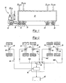
- Heavy vehicle 10 illustrated in Figure 1, includes a tractor 12 with a front steering axle 14 and a rear tandem drive axle 16.
- the front steering axle 14 can be either a non-driving axle or a driving axle.
- the tandem drive axle 16 is comprised of a front drive axle 18 and a rear drive axle 20.
- the tractor 12 pulls a trailer 22 which has a first trailer axle 24 and a second trailer axle 26.
- the trailer axles 24, 26 are typically non-drive axles.
- the invention also extends to vehicles and trailers with even more axles.
- each axle 14, 18, 20, 24, 26 are subject to a vertical downward force F.
- the front steering axle 14 is subject to a force F F.A. ;
- the front drive axle 18 is subject to a force F A.D.1
- the rear drive axle 20 is subject to a force F A.D.2
- the first trailer axle 24 is subject to a force F A.D.3
- the second trailer axle 26 is subject to a force F A.D.4 .
- the designation F.A. refers to a first axle while the designation A.D. refers to an additional axle.
- the load on the front axle 14 is comprised of the weight of the engine and other engine compartment components, the weight of the vehicle cab, and the weight of the driver. Once the vehicle is built this weight does not change except for small variations due to the different weights of different drivers. However, driver weight variation is usually less than one percent for the axle 14.
- the front axle 14 is preferably considered to be subject to a known or fixed load. For the case where the load changes due to the forward positioning of the attachment point between the tractor 12 and the trailer 22, the distribution of the acceleration experienced in the steering axle is compared to an expected distribution and the assumed steering axle weight is adjusted accordingly. This will be discussed in further detail below.
- a first accelerometer 28 is supported on the front steering axle 14 and measures the vertical acceleration of the front axle 14 as the vehicle 10 is moving.
- the accelerometer 28 is an instrument that measures vertical acceleration or the rate of change of velocity with respect to time and is well known in the art.
- Each additional axle 18, 20, 24, 26 on the vehicle 10 also supports an accelerometer 30, 32, 34, 36.
- the front drive axle 18 has a front drive accelerometer 30, the rear drive axle 20 has a rear drive accelerometer 32, the first trailer axle 24 has a first trailer accelerometer 34, and the second trailer axle 26 has a second trailer accelerometer 36.
- all of the accelerometers 28, 30, 32, 34, 36 are placed near or at the center 38 of their respective axle 14, 18, 20, 24, 26.
- Each of the additional accelerometers 30, 32, 34, 36 measures the vertical acceleration of its respective axle 18, 20, 24, 26.
- All of the accelerometers 28, 30, 32, 34, 36 are electrically linked to a central processor 40 or electronic control unit by means well known in the art.
- the central processor 40 is also well known in the art and is linked to an indicator 42 which displays the vehicle weight.
- the system operates in the following manner.
- One axle weight for the vehicle 10 must be known. Since weight on the front steering axle 14 remains relatively constant when the vehicle 10 is in the loaded or unloaded condition, this is the axle that is preferably used to satisfy this requirement, however, other axles could be used.
- the accelerometer 28 for the front steering axle 14 (the known axle) produces a first signal 44 based on these measured accelerations.
- the accelerometers for each of the additional axles also produce signals 46A, 46B, 46C, 46D based on their respective measured accelerations. These signals are combined by the processor 40 to form a second signal 46.
- the processor 40 determines the vehicle weight by comparing the second signal 46 to the first signal 44.
- the first accelerometer 28 measures a plurality of vertical accelerations for the front axle 14 and produces a plurality of first acceleration signals.
- the processor 40 bases the first signal 44 on the plurality of first acceleration signals by deriving the first signal 44 from a standard deviation calculated based on the plurality of first acceleration signals.
- the first signal 44 is comprised of a plurality of measured acceleration signals that are compiled together in the form of a standard deviation.
- Each of the additional accelerometers 30, 32, 34, 36 measures a plurality of accelerations for its respective additional axle 18, 20, 24, 26 and produces a plurality of acceleration signals for each of the additional axles 18, 20, 24, 26.
- signal 46A is comprised of a plurality of measured acceleration signals from front drive axle
- signal 46B is comprised of a plurality of measured acceleration signals from rear drive axle
- 46C is comprised of a plurality of measured acceleration signals from the first trailer axle
- 46D is comprised of a plurality of measured acceleration signals from the second trailer axle 26.
- the second signal 46 is comprised of a summation of the standard deviations calculated for each of the signals 46A, 46B, 46C, 46D based on their respective measured plurality of accelerations.
- the processor 40 first calculates a standard deviation for each of the additional axles 18, 20, 24, 26 based on the plurality of acceleration signals for the respective additional axle 18, 20, 24, 26. Then the processor 40 determines the second signal 46 based on summing the standard deviations for each of the additional axles 18, 20, 24, 26.
- This formula is based on physical observations that have been converted to mathematics., i.e., it has been observed that the behavior of the axles on the vehicle is load dependent.
- the vertical displacement experienced by an axle is much smaller when the axle has a heavy load than when it has a light load, thus the vertical accelerations are different for heavy loads and light loads.
- a Gaussian or normal curve comprised of a population of acceleration measurements made for each axle, is narrower for a heavy load than for a light load.
- a Gaussian curve is the bell-shaped curve corresponding to a population which has a normal distribution.
- the determination of a normal distribution is well known in the art and is based on the mean and variance of the population in relation to the specific data point in the population.
- a single data point in the population corresponds to a single acceleration measurement for an axle.
- An entire population is representative of a multitude of acceleration measurements. Enough data points need to be collected for each axle to be able to properly fit a Guassian curve for that axle.
- the number of data points needed can vary. For testing purposes an accelerometer took one hundred (100) measurements per second for ten (10) to twenty (20) minutes. This testing criteria resulted in the collection of a significant amount of data. It should be understood that the criteria discussed above is only one set of criteria and that many other sets of criteria could be used to determine the Guassian curve such as taking more or less than one hundred (100) acceleration measurements per second and for more than twenty minutes or less than 10 minutes.
- the standard deviation for that axle is determined.
- the standard deviation represents the positive square root of the expected value of the square of the difference between a random variable, in this case the vertical accelerations, and its mean.
- the weight of the vehicle is proportional to the standard deviations: W v ⁇ total ⁇ W F . A . ⁇ F . A . ⁇ W A . D .1 ⁇ A . D .1 ⁇ W A . D .2 ⁇ A . D .2 ⁇ W A . D .3 ⁇ A . D .3 ⁇ W A . D .4 ⁇ A . D .4 .
- W v In order to determine the-total vehicle weight, W v , based on the standard deviations, one of the axle weights needs to be known.
- the weight on the front steering axle In a tractor-trailer combination, typically the weight on the front steering axle is known because the weight is based on the weight of the engine and other engine compartment components, the weight of the cab, and the weight of the driver. This weight is determined when the vehicle is built and can be pre-programmed into the central processor 40. This weight on the front axle does not vary significantly during loaded and unloaded conditions and any weight variation due to the different weights of the drivers is typically less than one percent.
- the distribution of the acceleration experienced in the steering axle is compared to an expected distribution and the assumed steering axle weight is adjusted accordingly.
- the front steering axle vertical accelerations can be measured for the tractor 12 alone (no trailer 22 attached) for a typical interstate duty cycle at a given vehicle speed, for example, fifty miles per hour. These measurements become reference measurements, W F.A.ref and ⁇ F.A.ref .
- the front axle weigh, W F.A.ref is known, as discussed above, and the vertical acceleration measurements in this situation are taken so that a baseline standard deviation can be determined for comaprison to a front steering axle 14 with a trailer 22 attached to the tractor 12.
- a trailer 22 is hitched to the tractor 12 and the same interstate duty cycle is run at the same speed.
- W F.A. ⁇ F.A. / ⁇ F.A.ref .
- tractors 12 equipped with air suspension do have air bags in the drive axle 16 to make the driver's ride as comfortable as possible.
- the effect on the air bag pressure will can be measured to determine the weight of the drive axle.
- any axle weight can be determined if it includes an air suspension air bag. This means that axles other than the front steering axle 14 can be used as the known axle weight.
- the formula used to calculate the total vehicle weight was determined by trying various ratios between the weight and the standard deviations. A one to one ratio was found to be typical, i.e., if there was ten times the weight on an axle then the Gaussian curve was ten times narrower, as shown by the ratios between the axle weights and the standard deviation discussed above. Specifically, the following derivation was used.
- W v ( ⁇ total / ⁇ F .
- This formula, W v W F . A . ⁇ 1 + ⁇ ⁇ n ⁇ A . D . l + ... + ⁇ A . D . n ⁇ / ⁇ F . A . ⁇ , has been experimentally tested and proven to be accurate within one percent.
- the inventive method for determining the weight of the vehicle 10 is comprised of the following steps: (1) providing the first axle 14 subject to a known axle weight and having a first-accelerometer 28 and providing at least one additional axle 18, 20, 24, or 26 having an additional accelerometer 30, 32, 34, or 36, (2) producing a first signal 44 in response to measuring the acceleration of the first axle 14 with the first accelerometer 28, (3) producing a second signal 46 in response to measuring the acceleration of the additional axle 18, 20, 24, or 26 with the additional accelerometer 30, 32, 34, or 36, (4) determining the vehicle weight by comparing the second signal 46 to the first signal 44, and (5) indicating the vehicle weight to the vehicle operator.
- Additional steps include placing the first accelerometer 28 adjacent to a center 38 of the first axle 14 and placing the additional accelerometer 30, 32, ,34, or 36 adjacent to the center 38 of the additional axle 18, 20, 24, or 26.
- a plurality of additional axles 18, 20, 24, and 26 can be provided instead of having just one additional axle 18, 20, 24, or 26, with each additional axle 18, 20, 24, and 26 having a respective accelerometer 30, 32, 34, and 36 placed near the center 38 of the axle 18, 20, 24, and 26.
- An additional signal 46A, 46B, 46C, 46D is respectively produced for each additional axle 18, 20, 24, 26 in response to measuring the acceleration of each additional axle 18, 20, 24, 26 and the second signal 46 is determined by summing the additional signals 46A, 46B, 46C, 46D for each additional axle 18, 20, 24, 26.
- the method further includes the steps of: producing a plurality of first acceleration signals by measuring a plurality of accelerations of the first axle 14, determining the first signal 44 based on a standard deviation calculated from the plurality of first acceleration signals, producing a plurality of acceleration signals for each additional axle by measuring a plurality of accelerations for each additional axle 18, 20, 24, 26, determining a standard deviation for each additional axle 18, 20, 24, 26 based on the plurality of accelerations signals for each additional axle 18, 20, 24, 26, and determining the second signal 46 based on summing the standard deviations for each additional axle 18, 20, 24, 26.
- the present invention provides a system which continuously monitors the weight of a vehicle 10 while the vehicle 10 is in motion. This system is easily installed and maintained and is inexpensive.
Landscapes
- Physics & Mathematics (AREA)
- General Physics & Mathematics (AREA)
- Vehicle Body Suspensions (AREA)
Description
- This application relates to a unique system for determining the weight of a vehicle by using accelerometers to measure the accelerations of the vehicle axles as the vehicle is moving.
- Vehicles usually have maximum weight ratings which represent how much weight the vehicle can carry. Thus, it is important to know the weight of a vehicle during its operation. Overloading a vehicle can cause premature component wear resulting in high maintenance costs.
- Often it is difficult to tell how much weight has been loaded onto a vehicle. Vehicles carry various types of cargo or payload in varying amounts. During a single day, a vehicle may transfer any of these different types of loads to various locations where a new load may be picked up and the original load removed. This loading and unloading of cargo can take place several times a day. Thus, it is important for a vehicle operator to know the vehicle weight at all times during the operation of the vehicle.
- The most common method used for monitoring the weight of a vehicle is a scale. Typically, scales are located at the various sites where the vehicles are loaded or unloaded. The vehicle is driven onto the scale and the weight of the vehicle is measured while the vehicle is stationary. There are several drawbacks with this method. First, the scales are expensive and require continual maintenance to ensure proper calibration. Second, use of scales can be time consuming as there is usually only one scale per location with many vehicles waiting to be weighed. Finally, scales are not available at every location where a vehicle may be picking up a load, possibly due to the remoteness of the location or because the location is temporary. Thus, when the vehicle is loaded at such a location, an operator may not know exactly what the vehicle weight is and risks overloading the vehicle.
- Another method to monitor the payload of a vehicle uses a force sensor, such as a load cell or pressure transducer. This method is expensive because it requires the vehicle to be retrofitted to include pressure sensing airbags and load cells throughout the vehicle to measure pressure and determine weight under certain known or fixed height conditions.
- US-A-4,506,328 discloses a static low tire pressure detection system for an aircraft. The respective tire is mounted to a structural member which is subject to a bending load. An inclinometer is mounted at the structural member to sense the bend thereof. The bend can be used to determine whether or not the pressure of the respective tire is correct. It is indicated that an accelerometer can be used as an inclinometer. It is further indicated that the signals derived from the accelerometer can be used to determine the weight acting on the structural member.
- Thus, it is desirable to have an inexpensive system for determining the weight of a vehicle that continually monitors the vehicle weight and which is easily installed, maintained.
- The invention provides a method for determining the weight of a vehicle as defined in claim 1, and a system for determining the weight of a vehicle as defined in claim 6.
- Generally speaking, the system for determining the weight of a vehicle according to the invention includes a first axle subject to a known axle weight. Typically, the front steering axle for a tractor-trailer combination vehicle is used as the first axle. The load on this axle may be considered known as the load does not vary significantly throughout the operation of the vehicle. A first accelerometer is supported on the first axle and measures the acceleration of the first axle producing a first signal. Each additional axle on the vehicle, including any single rear or tandem drive axles and any trailer axles, is provided with an accelerometer. The accelerometers measure vertical accelerations for each respective axle. Each of these additional accelerometers produces a signal representative of its respective axle accelerations and these signals are combined to produce a second signal. A processor determines the vehicle weight by comparing the second signal to the first signal.
- The preferred inventive method for determining the weight of a vehicle the provides a first axle subject to a known axle weight and having a first accelerometer. At least one additional axle is provided with an additional accelerometer. A first signal is produced in response to measuring the acceleration of the first axle with the first accelerometer, and a second signal is produced in response to measuring the acceleration of the additional axle with the additional accelerometer. The vehicle weight is determined by comparing the second signal to the first signal. The vehicle weight may then be indicated to a vehicle operator.
- By providing accelerometers on each axle, the present invention allows the vehicle operator to continually monitor the weight of the vehicle once some initial samples have been collected. Moreover, the system is easily installed, easily maintained and is relatively inexpensive.
-
- Figure 1 is a side view of a vehicle using the inventive system.
- Figure 2 is a schematic overhead view of the present invention.
-
Heavy vehicle 10, illustrated in Figure 1, includes a tractor 12 with afront steering axle 14 and a reartandem drive axle 16. Thefront steering axle 14 can be either a non-driving axle or a driving axle. Thetandem drive axle 16 is comprised of afront drive axle 18 and arear drive axle 20. The tractor 12 pulls atrailer 22 which has afirst trailer axle 24 and asecond trailer axle 26. Thetrailer axles - When tha
vehicle 10 is in the unloaded condition, eachaxle front steering axle 14 is subject to a force FF.A.; thefront drive axle 18 is subject to a force FA.D.1, therear drive axle 20 is subject to a force FA.D.2, thefirst trailer axle 24 is subject to a force FA.D.3, and thesecond trailer axle 26 is subject to a force FA.D.4. The designation F.A. refers to a first axle while the designation A.D. refers to an additional axle. These designations are used to exemplify that the inventive system, discussed in detail below, can be utilized with a minimum of two axles, a first axle and one additional axle. The system can also be used on avehicle 10 with more than two axles, in other words the system can be used on avehicle 10 with a first axle and a plurality of additional axles. - When the
vehicle 10 is loaded such that the overall weight on eachadditional axle axles front steering axle 14. The weight on thisaxle 14 remains relatively constant in the unloaded and loaded conditions, however, the weight can vary depending on the point of attachment between the tractor 12 and thetrailer 22. If the point of attachment is moved forward enough, it can affect the weight being carried by thefront steering axle 14. The load on thefront axle 14 is comprised of the weight of the engine and other engine compartment components, the weight of the vehicle cab, and the weight of the driver. Once the vehicle is built this weight does not change except for small variations due to the different weights of different drivers. However, driver weight variation is usually less than one percent for theaxle 14. Thus, for the purposes of this invention thefront axle 14 is preferably considered to be subject to a known or fixed load. For the case where the load changes due to the forward positioning of the attachment point between the tractor 12 and thetrailer 22, the distribution of the acceleration experienced in the steering axle is compared to an expected distribution and the assumed steering axle weight is adjusted accordingly. This will be discussed in further detail below. - As shown in Figure 2, a
first accelerometer 28 is supported on thefront steering axle 14 and measures the vertical acceleration of thefront axle 14 as thevehicle 10 is moving. Theaccelerometer 28 is an instrument that measures vertical acceleration or the rate of change of velocity with respect to time and is well known in the art. - Each
additional axle vehicle 10 also supports anaccelerometer front drive axle 18 has afront drive accelerometer 30, therear drive axle 20 has arear drive accelerometer 32, thefirst trailer axle 24 has afirst trailer accelerometer 34, and thesecond trailer axle 26 has asecond trailer accelerometer 36. In the preferred embodiment, all of theaccelerometers center 38 of theirrespective axle additional accelerometers respective axle - All of the
accelerometers central processor 40 or electronic control unit by means well known in the art. Thecentral processor 40 is also well known in the art and is linked to anindicator 42 which displays the vehicle weight. - The system operates in the following manner. One axle weight for the
vehicle 10 must be known. Since weight on thefront steering axle 14 remains relatively constant when thevehicle 10 is in the loaded or unloaded condition, this is the axle that is preferably used to satisfy this requirement, however, other axles could be used. Once thevehicle 10 is moving theaccelerometers respective axles accelerometer 28 for the front steering axle 14 (the known axle) produces afirst signal 44 based on these measured accelerations. The accelerometers for each of the additional axles also producesignals processor 40 to form asecond signal 46. Theprocessor 40 determines the vehicle weight by comparing thesecond signal 46 to thefirst signal 44. - Specifically, the
first accelerometer 28 measures a plurality of vertical accelerations for thefront axle 14 and produces a plurality of first acceleration signals. Theprocessor 40 bases thefirst signal 44 on the plurality of first acceleration signals by deriving thefirst signal 44 from a standard deviation calculated based on the plurality of first acceleration signals. Thus, thefirst signal 44 is comprised of a plurality of measured acceleration signals that are compiled together in the form of a standard deviation. - Each of the
additional accelerometers additional axle additional axles front drive axle 18, signal 46B is comprised of a plurality of measured acceleration signals fromrear drive axle first trailer axle second trailer axle 26. - The
second signal 46 is comprised of a summation of the standard deviations calculated for each of thesignals processor 40 first calculates a standard deviation for each of theadditional axles additional axle processor 40 determines thesecond signal 46 based on summing the standard deviations for each of theadditional axles - The
processor 40 compares thefirst signal 44, representing the standard deviation for thefront axle 14 accelerations, to thesecond signal 46, representing the sum of the standard deviations for theadditional axle 
- This formula is based on physical observations that have been converted to mathematics., i.e., it has been observed that the behavior of the axles on the vehicle is load dependent. The vertical displacement experienced by an axle is much smaller when the axle has a heavy load than when it has a light load, thus the vertical accelerations are different for heavy loads and light loads. This means that a Gaussian or normal curve, comprised of a population of acceleration measurements made for each axle, is narrower for a heavy load than for a light load.
- As is well known in the art, a Gaussian curve is the bell-shaped curve corresponding to a population which has a normal distribution. The determination of a normal distribution is well known in the art and is based on the mean and variance of the population in relation to the specific data point in the population.
- Other factors such as speed and road conditions can affect the acceleration measurements. However, because the measurements are taken continuously while the vehicle is moving, the road conditions are the same for every axle. Also, the speed for each wheel will be the same, taking into account the possibility of having different tire sizes on the same vehicle.
- A single data point in the population corresponds to a single acceleration measurement for an axle. An entire population is representative of a multitude of acceleration measurements. Enough data points need to be collected for each axle to be able to properly fit a Guassian curve for that axle. The number of data points needed can vary. For testing purposes an accelerometer took one hundred (100) measurements per second for ten (10) to twenty (20) minutes. This testing criteria resulted in the collection of a significant amount of data. It should be understood that the criteria discussed above is only one set of criteria and that many other sets of criteria could be used to determine the Guassian curve such as taking more or less than one hundred (100) acceleration measurements per second and for more than twenty minutes or less than 10 minutes.
- Once a population has been collected for each axle, the standard deviation for that axle is determined. As it is well known in the art, the standard deviation represents the positive square root of the expected value of the square of the difference between a random variable, in this case the vertical accelerations, and its mean.
- Thus, based on the observations discussed above, there is a relationship between the weight of the vehicle and the standard deviations determined for each axle, i.e., the weight of the vehicle is proportional to the standard deviations:

- In order to determine the-total vehicle weight, Wv, based on the standard deviations, one of the axle weights needs to be known. In a tractor-trailer combination, typically the weight on the front steering axle is known because the weight is based on the weight of the engine and other engine compartment components, the weight of the cab, and the weight of the driver. This weight is determined when the vehicle is built and can be pre-programmed into the
central processor 40. This weight on the front axle does not vary significantly during loaded and unloaded conditions and any weight variation due to the different weights of the drivers is typically less than one percent. - As previously mentioned, for the case where the load changes due to the forward positioning of the attachment point between the tractor 12 and the
trailer 22, the distribution of the acceleration experienced in the steering axle is compared to an expected distribution and the assumed steering axle weight is adjusted accordingly. Specifically, the front steering axle vertical accelerations can be measured for the tractor 12 alone (notrailer 22 attached) for a typical interstate duty cycle at a given vehicle speed, for example, fifty miles per hour. These measurements become reference measurements, WF.A.ref and σF.A.ref. The front axle weigh, WF.A.ref is known, as discussed above, and the vertical acceleration measurements in this situation are taken so that a baseline standard deviation can be determined for comaprison to afront steering axle 14 with atrailer 22 attached to the tractor 12. Next, atrailer 22 is hitched to the tractor 12 and the same interstate duty cycle is run at the same speed. Vertical accelerations are measured and the axle weight is estimated based on comparing the vertical acceleration measurements for the front axle without atrailer 22 attached, to the vertical acceleration measurements for the front axle with thetrailer 22 attached, WF.A.ref/σF.A.ref = WF.A./σF.A.. Thus, the weight effect on thefront steering axle 14 due to the forward attachment of thetrailer 22 on the tractor 12 is estimated according to the formula: WF.A. = σF.A./σF.A.ref. - This is just one possible way to estimate the weight effect on the
front steering axle 14 of a forward attachment of thetrailer 22 to the tractor 12. Another possible way would be to measure the weight of the front steering axle 14 (on a tractor 12 with atrailer 22 attached) on a scale. This weight measurement would then be programmed into thecentral processor 40 and would become the known axle weight. Only this one axle would have to be measured on the scale, the additional axle weight and the total vehicle weight would then be determined according to the inventive method. - Finally, tractors 12 equipped with air suspension do have air bags in the
drive axle 16 to make the driver's ride as comfortable as possible. The effect on the air bag pressure will can be measured to determine the weight of the drive axle. Thus, any axle weight can be determined if it includes an air suspension air bag. This means that axles other than thefront steering axle 14 can be used as the known axle weight. - The formula used to calculate the total vehicle weight, was determined by trying various ratios between the weight and the standard deviations. A one to one ratio was found to be typical, i.e., if there was ten times the weight on an axle then the Gaussian curve was ten times narrower, as shown by the ratios between the axle weights and the standard deviation discussed above. Specifically, the following derivation was used. The total vehicle weight, is equal to the sum of the weights on each axle: Wv = WF.A. + WA.D.1 + WA.D.2 + WA.D.3 + WA.D.4. Thus, using this formula along with the proportional relations shown above, the following formula is derived:


- One advantage of determining the axle weights based on acceleration measurements taken while the vehicle is moving is that the dynamic axle load is measured for each axle. As long as the weight of one axle is known, all of the additional axle weights are known. In general, Wv = Wi [1 + {Σn σAi, /σAi}], where Wi is the weight on axle "i" and σAi is the standard deviation of the vertical accelerations measured on axle "i." Thus, individual axle weights can be continuously monitored throughout the operation of the vehicle to determine whether loads are shifting. While these dynamic axle loads measured as the vehicle moves can vary, the total dynamic vehicle weight will be equal to the total static vehicle weight.
- The inventive method for determining the weight of the
vehicle 10 is comprised of the following steps: (1) providing thefirst axle 14 subject to a known axle weight and having a first-accelerometer 28 and providing at least oneadditional axle additional accelerometer first signal 44 in response to measuring the acceleration of thefirst axle 14 with thefirst accelerometer 28, (3) producing asecond signal 46 in response to measuring the acceleration of theadditional axle additional accelerometer second signal 46 to thefirst signal 44, and (5) indicating the vehicle weight to the vehicle operator. - Additional steps include placing the
first accelerometer 28 adjacent to acenter 38 of thefirst axle 14 and placing theadditional accelerometer center 38 of theadditional axle additional axles additional axle additional axle respective accelerometer center 38 of theaxle - An
additional signal additional axle additional axle second signal 46 is determined by summing theadditional signals additional axle - Specifically, the method further includes the steps of: producing a plurality of first acceleration signals by measuring a plurality of accelerations of the
first axle 14, determining thefirst signal 44 based on a standard deviation calculated from the plurality of first acceleration signals, producing a plurality of acceleration signals for each additional axle by measuring a plurality of accelerations for eachadditional axle additional axle additional axle second signal 46 based on summing the standard deviations for eachadditional axle - In summary, the present invention provides a system which continuously monitors the weight of a
vehicle 10 while thevehicle 10 is in motion. This system is easily installed and maintained and is inexpensive. - While a preferred vehicle configuration has been disclosed, it should be understood that the inventive system can be used with a minimum of two axles and can also be used with any number of additional axles.
Claims (20)
- A method for determining the weight of a vehicle comprising the steps of:1) providing a first axle (14) subject to a known axle weight and having a first accelerometer (28) and providing at least one additional axle (18, 20, 24, 26) having an additional accelerometer (30, 32, 34, 36);2) producing a first signal (44) in response to measuring the acceleration of the first axle (14) with the first accelerometer (28);3) producing a second signal (46) in response to measuring the acceleration of the additional axle (18, 20, 24, 26) with the additional accelerometer (30, 32, 34, 36);4) determining the vehicle weight by comparing the second signal (46A, 46B, 46C, 46D) to the first signal (44); and5) indicating the vehicle weight to a vehicle operator.
- A method as recited in Claim 1 further including the steps of placing the first accelerometer (28) adjacent to a center of the first axle (14) and placing the additional accelerometer (30, 32, 34, 36) adjacent to the center of the additional axle (18, 20, 24, 26).
- A method as recited in Claim 1 further including the steps of providing a plurality of additional axles (18, 20, 24, 26) such that the at least one additional axle (18, 20, 24, 26) is comprised of a plurality of additional axles (18, 20, 24, 26), each additional axle (18, 20, 24, 26) having a respective accelerometer (30, 32, 34, 36);
placing the first accelerometer (28) adjacent to a center of the first axle (14);
placing the accelerometers (30, 32, 34, 36) of each additional axle (18, 20, 24, 26) adjacent to a center of the respective additional axle (18, 20, 24, 26);
producing an additional signal (46A, 46B, 46C, 46D) for each additional axle (18, 20, 24, 26) in response to measuring the acceleration of each additional axle (18, 20, 24, 26) with its respective accelerometer (30, 32, 34, 36); and
determining the second signal (46) by summing the additional signals for each additional axle (18, 20, 24, 26). - A method as recited in Claim 3 further including the steps of producing a plurality of first acceleration signals by measuring a plurality of accelerations of the first axle (14);
determining the first signal (44) based on a standard deviation determined from the plurality of first acceleration signals;
producing a plurality of acceleration signals for each additional axle (18, 20, 24, 26) by measuring a plurality of accelerations for each additional axle (18, 20, 24, 26);
determining a standard deviation for each additional axle (18, 20, 24, 26) based on the plurality of accelerations signals (46A, 46B, 46C, 46D) for each additional axle (18, 20, 24, 26); and
determining the second signal (46) based on summing the standard deviations for each additional axle (18, 20, 24, 26). - A method as recited in Claim 4 wherein the determination of the vehicle weight is according to the following formula

- A system for determining the weight of a vehicle comprising
a first axle (14) subject to a known axle weight;
at least one additional axle (18, 20, 24, 26);
a first accelerometer (28) for measuring the acceleration of the first axle (14) and producing a first signal (44);
at least one additional accelerometer (30, 32, 34, 36) for measuring the acceleration of the additional axle (18, 20, 24, 26) and producing a second signal (46); and
a processor (40) for determining the vehicle weight by comparing the second signal (46) to the first signal (44). - A system as recited in Claim 6 including an indicator (42) for indicating the vehicle weight to a vehicle operator.
- A system as recited in Claim 6 wherein said first axle (14) includes a first axle (14) center and said additional axle (18, 20, 24, 26) includes an additional axle center, said first accelerometer (28) being supported on said first axle (14) adjacent said first axle center and said additional accelerator (30, 32, 34, 36) being supported on said additional axle (18, 20, 24, 26) adjacent said additional axle center.
- A system as recited in Claim 6 wherein said at least one additional axle (18, 20, 24, 26) is comprised of a plurality of additional axles (18, 20, 24, 26) and said at least one additional accelerometer (30, 32, 34, 36) is comprised of a plurality of additional accelerometers (30, 32, 34, 36) whereby each additional axle (18, 20, 24, 26) supports one of said additional accelerometers (30, 32, 34, 36) for measuring the acceleration of said additional axle (18, 20, 24, 26).
- A system as recited in Claim 9 wherein each additional accelerometer (30, 32, 34, 36) is supported adjacent to a center of its respective additional axle (18, 20, 24, 26).
- A system as recited in Claim 10 wherein each of said additional accelerometers (30, 32, 34, 36) produces an additional signal (46A, 46B, 46C, 46D) for its respective additional axle (18, 20, 24, 26) in response to measuring the acceleration of said additional axle (18, 20, 24, 26) and said processor (40) determines said second signal (46) by summing the additional signals (46A, 46B, 46C, 46D) for each additional axle (18, 20, 24, 26).
- A system as recited in Claim 11 wherein said first accelerometer (28) measures a plurality of accelerations for said first axle (14) and produces a plurality of first acceleration signals;
each of said additional accelerometers (30, 32, 34, 36) measures a plurality of accelerations for its respective additional axle (18, 20, 24, 26) and produces a plurality of additional accelerations signals (46A, 46B, 46C, 46D) for each of said additional axles (18, 20, 24, 26); and
said processor (40) determines said first signal (44) based on said plurality of first acceleration signals and determines said second signal (46) based on said plurality of said additional acceleration signals (46A, 46B, 46C, 46D). - A system as recited in Claim 12 wherein said processor (40) determines the first signal (44) based on a standard deviation derived from the plurality of first acceleration signals, determines a standard deviation for each of said additional axles (18, 20, 24, 26) based on said plurality of acceleration signals (46A, 46B, 46C, 46D) for said respective additional axle (18, 20, 24, 26), and determines the second signal (46) based on summing the standard deviations for each of said additional axles (18, 20, 24, 26).
- A system as recited in Claim 13 wherein said processor (40) determines the vehicle weight is according to the following formula

wherein Wv is the vehicle weight, WF.A. is the known axle weight of the first axle (14), σF.A. is the standard deviation calculated for the first axle (14), and Σn (σA.D.1 + ... + σA.D.n represents the summation of the standard deviations determined for each additional axle (18, 20, 24, 26) in which n represents an integer of the series n = 1, 2, 3, ... , and n is equal to the number of additional axles (18, 20, 24, 26). - A system as recited in Claim 6 wherein said first axle (14) is a steering axle.
- A system as recited in Claim 15 wherein said at least one additional axle (18, 20, 24, 26) is a driving axle.
- A system as recited in Claim 16 wherein said at least one additional axle (18, 20, 24, 26) is comprised of a plurality of additional axles (18, 20, 24, 26) including at least one drive axle and at least one trailer axle.
- A system as recited in Claim 17 wherein said at least one additional accelerometer (30, 32, 34, 36) is comprised of a plurality of additional accelerometers (30, 32, 34, 36) including a drive axle accelerometer for measuring the acceleration of said drive axle (30, 32) and a trailer axle accelerometer (34, 36) for measuring the acceleration of said trailer axle.
- A system as recited in Claim 18 wherein said first accelerometer (28) measures a plurality of accelerations for said steering axle (14) and produces a plurality of first acceleration signals and said processor (40) determines said first signal (44) based on the standard deviation derived from said plurality of first acceleration signals;
said drive axle accelerometer (30, 32) measures a plurality of accelerations for said drive axle and produces a plurality of drive axle acceleration signals (46A, 46B);
said trailer axle accelerometer (34, 36) measures a plurality of accelerations for said trailer axle and produces a plurality of trailer axle accelerations signals (46C, 46D);
said processor (40) determines a drive axle standard deviation derived from said plurality of drive axle accelerations signals (46A, 46B) and determines a trailer axle standard deviation derived from said plurality of trailer axle accelerations signals (46C, 46D), said processor (40) determining said second signal (46A, 46B, 46C, 46D) based on a summation of said drive axle and trailer axle standard deviations; and
said processor (40) determines the weight of said vehicle by dividing said second signal (46) by said first signal (44) thereby producing a signal ratio, adding said signal ratio to a constant, and multiplying this quantity by the known axle weight of said steering axle (14) . - A system as recited in claim 6 wherein the vehicle has
at least one drive axle (18, 20) having a second accelerometer (30, 32) for measuring the acceleration of said drive axle and producing a drive axle signal (46A, 46B);
a least one trailer axle (24, 26) having a third accelerometer (34, 36) for measuring the acceleration of said trailer axle (24, 26) and producing a trailer axle signal (46C, 46D); and
the processor (40) combining said drive axle signal (46A, 46B) and said trailer axle signal (46C, 46D) to form said second signal (46), said processor (40) determining the vehicle weight by comparing said second signal (46) to said first signal (44).
Applications Claiming Priority (2)
| Application Number | Priority Date | Filing Date | Title |
|---|---|---|---|
| US10107 | 1993-01-28 | ||
| US09/010,107 US5877455A (en) | 1998-01-21 | 1998-01-21 | Payload monitoring for a tractor-trailer |
Publications (2)
| Publication Number | Publication Date |
|---|---|
| EP0932032A1 EP0932032A1 (en) | 1999-07-28 |
| EP0932032B1 true EP0932032B1 (en) | 2006-05-31 |
Family
ID=21743914
Family Applications (1)
| Application Number | Title | Priority Date | Filing Date |
|---|---|---|---|
| EP99100353A Expired - Lifetime EP0932032B1 (en) | 1998-01-21 | 1999-01-14 | Payload monitoring for a tractor-trailer |
Country Status (3)
| Country | Link |
|---|---|
| US (1) | US5877455A (en) |
| EP (1) | EP0932032B1 (en) |
| DE (1) | DE69931535T2 (en) |
Cited By (5)
| Publication number | Priority date | Publication date | Assignee | Title |
|---|---|---|---|---|
| US10696109B2 (en) | 2017-03-22 | 2020-06-30 | Methode Electronics Malta Ltd. | Magnetolastic based sensor assembly |
| US11084342B2 (en) | 2018-02-27 | 2021-08-10 | Methode Electronics, Inc. | Towing systems and methods using magnetic field sensing |
| US11135882B2 (en) | 2018-02-27 | 2021-10-05 | Methode Electronics, Inc. | Towing systems and methods using magnetic field sensing |
| US11221262B2 (en) | 2018-02-27 | 2022-01-11 | Methode Electronics, Inc. | Towing systems and methods using magnetic field sensing |
| US11491832B2 (en) | 2018-02-27 | 2022-11-08 | Methode Electronics, Inc. | Towing systems and methods using magnetic field sensing |
Families Citing this family (30)
| Publication number | Priority date | Publication date | Assignee | Title |
|---|---|---|---|---|
| DE19827268A1 (en) * | 1998-06-19 | 1999-12-30 | Pfreundt Gmbh & Co Kg | Weight measurement of useful load of lorry with vertical sensors applicable to different vehicles |
| US6363331B1 (en) * | 1998-12-09 | 2002-03-26 | Meritor Heavy Vehicle Systems, Llc | Weight distribution monitor |
| US6692567B1 (en) * | 1999-10-06 | 2004-02-17 | Vortek Llc | Seismic weigh-in-motion system |
| US7206775B2 (en) * | 2000-07-06 | 2007-04-17 | Microsoft Corporation | System and methods for the automatic transmission of new, high affinity media |
| US7035873B2 (en) * | 2001-08-20 | 2006-04-25 | Microsoft Corporation | System and methods for providing adaptive media property classification |
| US6863149B2 (en) * | 2000-12-12 | 2005-03-08 | Japan Science And Technology Corporation | Steering mechanism of electric car |
| US6499552B2 (en) | 2001-06-01 | 2002-12-31 | Meritor Heavy Vehicle Technology, L.L.C. | Drive axle control system |
| US20040084226A1 (en) * | 2002-10-31 | 2004-05-06 | Alfred Wright | Auto weight |
| DE10337212B4 (en) * | 2003-08-13 | 2015-10-01 | Volkswagen Ag | System and method for determining a loading state of a vehicle or a trailer |
| SE527692C2 (en) * | 2004-05-12 | 2006-05-09 | Hans Ekdahl Med Hg Ekdahl Kons | Procedure in a communication network to distribute driving information for vehicles and systems implementing the procedure |
| US7472002B2 (en) * | 2005-06-28 | 2008-12-30 | Dana Heavy Vehicle Systems, Llc | Method of estimating vehicle weight by determining vertical oscillation frequency |
| US9120493B2 (en) * | 2007-04-30 | 2015-09-01 | General Electric Company | Method and apparatus for determining track features and controlling a railroad train responsive thereto |
| US20090095194A1 (en) * | 2007-10-12 | 2009-04-16 | Ajith Kuttannair Kumar | System and method for dynamically affecting a force applied through a rail vehicle axle |
| US20090099714A1 (en) * | 2007-10-12 | 2009-04-16 | Ajith Kuttannair Kumar | System and method for dynamically determining a force applied through a rail vehicle axle |
| US7818140B2 (en) * | 2008-01-29 | 2010-10-19 | Zf Friedrichshafen Ag | System for estimating a vehicle mass |
| US20140000969A1 (en) * | 2009-05-29 | 2014-01-02 | David Carruthers | Vehicle load sensing system |
| US8957770B2 (en) | 2010-03-31 | 2015-02-17 | Shanghai Baolong Automotive Corporation | Automatic networking apparatus and system for vehicles |
| DE102012216306A1 (en) * | 2012-09-13 | 2014-03-13 | Zf Friedrichshafen Ag | Method for determining load of working machine e.g. agricultural machine, involves determining loading of work machine based on comparison of detected force and unloaded state of work machine corresponding to reference value |
| US10831859B2 (en) * | 2012-11-07 | 2020-11-10 | Ford Global Technologies, Llc | Hardware and controls for personal vehicle rental |
| US9109942B2 (en) * | 2013-04-15 | 2015-08-18 | Caterpillar Inc. | Method of calculating payload material weight and machine using same |
| CN104457937B (en) * | 2014-10-11 | 2017-01-18 | 中国第一汽车股份有限公司 | Method for calculating gross vehicle weight and fuel-saving control method |
| DE18907724T1 (en) | 2018-02-27 | 2021-03-25 | Methode Electronics, Inc. | Towing systems and methods using magnetic field measurement |
| US11014417B2 (en) | 2018-02-27 | 2021-05-25 | Methode Electronics, Inc. | Towing systems and methods using magnetic field sensing |
| US10207866B1 (en) * | 2018-03-22 | 2019-02-19 | Rubicon Global Holdings, Llc | Load monitoring system using acceleration of the vehicle for waste service vehicle |
| US10782179B2 (en) * | 2018-10-22 | 2020-09-22 | Goodrich Corporation | On-board unit load device weight estimation |
| US11519776B2 (en) | 2019-06-13 | 2022-12-06 | Dana Heavy Vehicle Systems Group, Llc | System and method for determining axle load |
| US11333547B2 (en) * | 2019-10-25 | 2022-05-17 | Blackberry Limited | Method and system for shipping container loading and unloading estimation |
| US11796380B2 (en) | 2021-07-09 | 2023-10-24 | Ford Global Technologies, Llc | Methods and apparatus to calibrate a weight estimation |
| US12158369B2 (en) * | 2021-10-29 | 2024-12-03 | Cistant, LLC | Systems and methods for determining a weight rating of a transporter |
| US12529589B2 (en) * | 2022-09-19 | 2026-01-20 | Ford Global Technologies, Llc | Methods and apparatus to detect loads lost from vehicles during transit |
Citations (1)
| Publication number | Priority date | Publication date | Assignee | Title |
|---|---|---|---|---|
| US4506328A (en) * | 1982-07-30 | 1985-03-19 | Sundstrand Data Control, Inc. | Static low tire pressure detection system for aircraft |
Family Cites Families (10)
| Publication number | Priority date | Publication date | Assignee | Title |
|---|---|---|---|---|
| US3428139A (en) * | 1968-06-10 | 1969-02-18 | Earl C Nolan | Ultrasonic type net weight load indicator for vehicles |
| US4391338A (en) * | 1980-04-04 | 1983-07-05 | Harvey Patashnick | Microbalance and method for measuring the mass of matter suspended within a fluid medium |
| JPS5855719A (en) * | 1981-09-29 | 1983-04-02 | Mitsubishi Motors Corp | Detector for live load for vehicle |
| DE3246201A1 (en) * | 1982-12-14 | 1984-06-14 | Wabco Westinghouse Fahrzeugbremsen GmbH, 3000 Hannover | METHOD AND DEVICE FOR DETERMINING THE WEIGHT OF A VEHICLE |
| US4651838A (en) * | 1984-10-15 | 1987-03-24 | Hamilton James M | Air spring control system and method |
| EP0285689A1 (en) * | 1987-04-08 | 1988-10-12 | Franz Kirchberger | Method for the determination of the weight of a load transported by an agricultural tractor, and device for carrying out this method |
| US5215154A (en) * | 1988-08-23 | 1993-06-01 | John Kirby | Method and apparatus for measuring vehicle weight or engine power or both |
| GB8819937D0 (en) * | 1988-08-23 | 1988-09-21 | Kirby J | Weighing vehicles |
| US4854407A (en) * | 1988-08-30 | 1989-08-08 | Wagner William C | System for measuring air pressure on drive axles of road tractor trailers and load distribution |
| DE3843818C1 (en) * | 1988-12-24 | 1990-05-10 | Daimler-Benz Aktiengesellschaft, 7000 Stuttgart, De |
-
1998
- 1998-01-21 US US09/010,107 patent/US5877455A/en not_active Expired - Lifetime
-
1999
- 1999-01-14 EP EP99100353A patent/EP0932032B1/en not_active Expired - Lifetime
- 1999-01-14 DE DE69931535T patent/DE69931535T2/en not_active Expired - Lifetime
Patent Citations (1)
| Publication number | Priority date | Publication date | Assignee | Title |
|---|---|---|---|---|
| US4506328A (en) * | 1982-07-30 | 1985-03-19 | Sundstrand Data Control, Inc. | Static low tire pressure detection system for aircraft |
Cited By (6)
| Publication number | Priority date | Publication date | Assignee | Title |
|---|---|---|---|---|
| US10696109B2 (en) | 2017-03-22 | 2020-06-30 | Methode Electronics Malta Ltd. | Magnetolastic based sensor assembly |
| US10940726B2 (en) | 2017-03-22 | 2021-03-09 | Methode Electronics Malta Ltd. | Magnetoelastic based sensor assembly |
| US11084342B2 (en) | 2018-02-27 | 2021-08-10 | Methode Electronics, Inc. | Towing systems and methods using magnetic field sensing |
| US11135882B2 (en) | 2018-02-27 | 2021-10-05 | Methode Electronics, Inc. | Towing systems and methods using magnetic field sensing |
| US11221262B2 (en) | 2018-02-27 | 2022-01-11 | Methode Electronics, Inc. | Towing systems and methods using magnetic field sensing |
| US11491832B2 (en) | 2018-02-27 | 2022-11-08 | Methode Electronics, Inc. | Towing systems and methods using magnetic field sensing |
Also Published As
| Publication number | Publication date |
|---|---|
| EP0932032A1 (en) | 1999-07-28 |
| US5877455A (en) | 1999-03-02 |
| DE69931535D1 (en) | 2006-07-06 |
| DE69931535T2 (en) | 2007-06-06 |
Similar Documents
| Publication | Publication Date | Title |
|---|---|---|
| US5877455A (en) | Payload monitoring for a tractor-trailer | |
| US6363331B1 (en) | Weight distribution monitor | |
| US6339749B1 (en) | Device for determining the weight of a motor vehicle | |
| US6526334B1 (en) | Method of controlling vehicle handling | |
| US5610372A (en) | System for measuring total weight and weight distribution of a vehicle | |
| US6426694B1 (en) | Method and apparatus for determining vehicle speed | |
| US6202020B1 (en) | Method and system for determining condition of road | |
| US6601013B2 (en) | Method and apparatus configured to determine the weight of a machine payload | |
| US8380390B2 (en) | Method and system of determining load characteristics of a trailer | |
| US5182712A (en) | Dynamic payload monitor | |
| EP1604179B1 (en) | System for vehicle axle load measurement with hysteresis compensation and acceleration filter | |
| US6449582B1 (en) | Vehicle weight and cargo load determination using tire pressure | |
| EP2215438B1 (en) | Estimation of the load of a vehicle | |
| US8630753B2 (en) | Method for dynamic determination of the true mass of a non rigid body subject to low frequency noise | |
| EP0489562B1 (en) | Method of detecting a deflated tyre on a vehicle | |
| CN205607509U (en) | Vehicle dynamic real -time monitoring system | |
| JP2686843B2 (en) | Vehicle loading weight measurement device | |
| CN108896149A (en) | Vehicle weighing method and vehicle | |
| US5215154A (en) | Method and apparatus for measuring vehicle weight or engine power or both | |
| US6405109B1 (en) | Axle misalignment method for a vehicle | |
| CN105865598A (en) | Dynamic real-time monitoring system and method of car | |
| JP2019113373A (en) | Wheel load estimation device | |
| EP4086595A1 (en) | A computer implemented method for controlling a vehicle | |
| US7142102B2 (en) | Weight overload warning system | |
| CN112270828A (en) | Vehicle early warning method and device, electronic equipment and vehicle |
Legal Events
| Date | Code | Title | Description |
|---|---|---|---|
| PUAI | Public reference made under article 153(3) epc to a published international application that has entered the european phase |
Free format text: ORIGINAL CODE: 0009012 |
|
| AK | Designated contracting states |
Kind code of ref document: A1 Designated state(s): DE GB |
|
| AX | Request for extension of the european patent |
Free format text: AL;LT;LV;MK;RO;SI |
|
| 17P | Request for examination filed |
Effective date: 20000125 |
|
| AKX | Designation fees paid |
Free format text: DE GB |
|
| 17Q | First examination report despatched |
Effective date: 20050426 |
|
| GRAP | Despatch of communication of intention to grant a patent |
Free format text: ORIGINAL CODE: EPIDOSNIGR1 |
|
| GRAS | Grant fee paid |
Free format text: ORIGINAL CODE: EPIDOSNIGR3 |
|
| GRAA | (expected) grant |
Free format text: ORIGINAL CODE: 0009210 |
|
| AK | Designated contracting states |
Kind code of ref document: B1 Designated state(s): DE GB |
|
| REG | Reference to a national code |
Ref country code: GB Ref legal event code: FG4D |
|
| REF | Corresponds to: |
Ref document number: 69931535 Country of ref document: DE Date of ref document: 20060706 Kind code of ref document: P |
|
| PLBE | No opposition filed within time limit |
Free format text: ORIGINAL CODE: 0009261 |
|
| STAA | Information on the status of an ep patent application or granted ep patent |
Free format text: STATUS: NO OPPOSITION FILED WITHIN TIME LIMIT |
|
| 26N | No opposition filed |
Effective date: 20070301 |
|
| PGFP | Annual fee paid to national office [announced via postgrant information from national office to epo] |
Ref country code: GB Payment date: 20100113 Year of fee payment: 12 Ref country code: DE Payment date: 20100107 Year of fee payment: 12 |
|
| GBPC | Gb: european patent ceased through non-payment of renewal fee |
Effective date: 20110114 |
|
| PG25 | Lapsed in a contracting state [announced via postgrant information from national office to epo] |
Ref country code: GB Free format text: LAPSE BECAUSE OF NON-PAYMENT OF DUE FEES Effective date: 20110114 |
|
| REG | Reference to a national code |
Ref country code: DE Ref legal event code: R119 Ref document number: 69931535 Country of ref document: DE Effective date: 20110802 |
|
| PG25 | Lapsed in a contracting state [announced via postgrant information from national office to epo] |
Ref country code: DE Free format text: LAPSE BECAUSE OF NON-PAYMENT OF DUE FEES Effective date: 20110802 |