EP0932025B1 - Actuator of a paper or board machine - Google Patents
Actuator of a paper or board machine Download PDFInfo
- Publication number
- EP0932025B1 EP0932025B1 EP99660011A EP99660011A EP0932025B1 EP 0932025 B1 EP0932025 B1 EP 0932025B1 EP 99660011 A EP99660011 A EP 99660011A EP 99660011 A EP99660011 A EP 99660011A EP 0932025 B1 EP0932025 B1 EP 0932025B1
- Authority
- EP
- European Patent Office
- Prior art keywords
- shaft
- actuator
- motor
- detection point
- hall sensor
- Prior art date
- Legal status (The legal status is an assumption and is not a legal conclusion. Google has not performed a legal analysis and makes no representation as to the accuracy of the status listed.)
- Expired - Lifetime
Links
Images
Classifications
-
- G—PHYSICS
- G01—MEASURING; TESTING
- G01D—MEASURING NOT SPECIALLY ADAPTED FOR A SPECIFIC VARIABLE; ARRANGEMENTS FOR MEASURING TWO OR MORE VARIABLES NOT COVERED IN A SINGLE OTHER SUBCLASS; TARIFF METERING APPARATUS; MEASURING OR TESTING NOT OTHERWISE PROVIDED FOR
- G01D5/00—Mechanical means for transferring the output of a sensing member; Means for converting the output of a sensing member to another variable where the form or nature of the sensing member does not constrain the means for converting; Transducers not specially adapted for a specific variable
- G01D5/12—Mechanical means for transferring the output of a sensing member; Means for converting the output of a sensing member to another variable where the form or nature of the sensing member does not constrain the means for converting; Transducers not specially adapted for a specific variable using electric or magnetic means
- G01D5/14—Mechanical means for transferring the output of a sensing member; Means for converting the output of a sensing member to another variable where the form or nature of the sensing member does not constrain the means for converting; Transducers not specially adapted for a specific variable using electric or magnetic means influencing the magnitude of a current or voltage
- G01D5/142—Mechanical means for transferring the output of a sensing member; Means for converting the output of a sensing member to another variable where the form or nature of the sensing member does not constrain the means for converting; Transducers not specially adapted for a specific variable using electric or magnetic means influencing the magnitude of a current or voltage using Hall-effect devices
- G01D5/145—Mechanical means for transferring the output of a sensing member; Means for converting the output of a sensing member to another variable where the form or nature of the sensing member does not constrain the means for converting; Transducers not specially adapted for a specific variable using electric or magnetic means influencing the magnitude of a current or voltage using Hall-effect devices influenced by the relative movement between the Hall device and magnetic fields
-
- G—PHYSICS
- G05—CONTROLLING; REGULATING
- G05B—CONTROL OR REGULATING SYSTEMS IN GENERAL; FUNCTIONAL ELEMENTS OF SUCH SYSTEMS; MONITORING OR TESTING ARRANGEMENTS FOR SUCH SYSTEMS OR ELEMENTS
- G05B19/00—Program-control systems
- G05B19/02—Program-control systems electric
- G05B19/18—Numerical control [NC], i.e. automatically operating machines, in particular machine tools, e.g. in a manufacturing environment, so as to execute positioning, movement or co-ordinated operations by means of program data in numerical form
- G05B19/19—Numerical control [NC], i.e. automatically operating machines, in particular machine tools, e.g. in a manufacturing environment, so as to execute positioning, movement or co-ordinated operations by means of program data in numerical form characterised by positioning or contouring control systems, e.g. to control position from one programmed point to another or to control movement along a programmed continuous path
- G05B19/21—Numerical control [NC], i.e. automatically operating machines, in particular machine tools, e.g. in a manufacturing environment, so as to execute positioning, movement or co-ordinated operations by means of program data in numerical form characterised by positioning or contouring control systems, e.g. to control position from one programmed point to another or to control movement along a programmed continuous path using an incremental digital measuring device
- G05B19/23—Numerical control [NC], i.e. automatically operating machines, in particular machine tools, e.g. in a manufacturing environment, so as to execute positioning, movement or co-ordinated operations by means of program data in numerical form characterised by positioning or contouring control systems, e.g. to control position from one programmed point to another or to control movement along a programmed continuous path using an incremental digital measuring device for point-to-point control
- G05B19/231—Numerical control [NC], i.e. automatically operating machines, in particular machine tools, e.g. in a manufacturing environment, so as to execute positioning, movement or co-ordinated operations by means of program data in numerical form characterised by positioning or contouring control systems, e.g. to control position from one programmed point to another or to control movement along a programmed continuous path using an incremental digital measuring device for point-to-point control the positional error is used to control continuously the servomotor according to its magnitude
- G05B19/232—Numerical control [NC], i.e. automatically operating machines, in particular machine tools, e.g. in a manufacturing environment, so as to execute positioning, movement or co-ordinated operations by means of program data in numerical form characterised by positioning or contouring control systems, e.g. to control position from one programmed point to another or to control movement along a programmed continuous path using an incremental digital measuring device for point-to-point control the positional error is used to control continuously the servomotor according to its magnitude with speed feedback only
-
- Y—GENERAL TAGGING OF NEW TECHNOLOGICAL DEVELOPMENTS; GENERAL TAGGING OF CROSS-SECTIONAL TECHNOLOGIES SPANNING OVER SEVERAL SECTIONS OF THE IPC; TECHNICAL SUBJECTS COVERED BY FORMER USPC CROSS-REFERENCE ART COLLECTIONS [XRACs] AND DIGESTS
- Y10—TECHNICAL SUBJECTS COVERED BY FORMER USPC
- Y10T—TECHNICAL SUBJECTS COVERED BY FORMER US CLASSIFICATION
- Y10T137/00—Fluid handling
- Y10T137/8158—With indicator, register, recorder, alarm or inspection means
- Y10T137/8225—Position or extent of motion indicator
- Y10T137/8242—Electrical
Definitions
- the invention relates to an actuator for a paper or board machine in accordance with the preamble of claims 1 and 2.
- Actuators are used, for example, to control the flow of different media, such as water and steam, in different processes.
- the actuators control a valve, nozzle or the like supplying the medium.
- the actuator can be a motor, cylinder or the like, which can be controlled in many different ways, for example mechanically, electrically, hydraulically or pneumatically.
- US Patent 4 662 398 discloses a valve controlling the flow of steam and air to the steam box of an apparatus for drying a fiber web.
- the valve is controlled by a stepping motor.
- the control arrangement of the stepping motor is very complicated, and it is uncertain whether the motor will operate reliably in the very difficult process conditions of a paper machine. Further, the positioning data of the valve, defined solely on the basis of the control of the stepping motor, is rather unreliable.
- DE Utility Model 29 701 674 discloses an actuator comprising a valve that is controlled by a brushless electrical motor.
- the position of the rotor of the brushless motor is measured by means of Hall sensors, and so the position of the actuator is also defined on the basis of the pulses generated by the Hall sensor.
- the publication teaches that the Hall sensor is also particularly used to effect the rotating motion of the motor.
- the control system of the brushless motor is complicated, and the rotation of the rotor is also difficult and complicated to measure. It is thus out of the question to use the sensor defining the position of the rotor and the brushless motor in the processing conditions of a paper machine.
- FI Patent 85 731 discloses actuators whose spindles are adjusted by stepping motors.
- the position of the spindles is measured by LVDT sensors.
- the control arrangement of the stepping motor is complicated and cumbersome.
- the LVDT sensor endures the process conditions of a paper machine rather poorly, and it is susceptible to malfunction.
- the signal generated by the LVDT sensor is also very weak, and for example due to great temperature dependence, the accuracy of the sensor is rather poor.
- GB Patent Application 2 225 415 discloses a fluid flow valve controlled by a stepping motor.
- the position of the valve can be measured by an optical shaft encoder.
- the optical encoder requires a complicated and sensitive electronic arrangement, which is difficult to arrange in conjunction with a paper machine: the optical encoders do not endure the process conditions of a paper machine.
- Document DE 37 26 885 A discloses an actuator comprising a motor which drives a shaft when the position of the actuator in the linear direction is adjusted by rotating the shaft.
- a sensor is used for measuring the rotation of the shaft, to generate a pulse output proportional to the rotation of the shaft, and for defining the position of the actuator in the linear direction, a sensor is used comprising a Hall sensor which generates a pulse when a detection point of the shaft revolves past the Hall sensor.
- Document DE 195 06 938 A1 discloses a device for measuring the rotating angle of a rotating member.
- This device comprises two detection point wheels in engagement with a cogwheel wherein the rim of the cogwheel is larger than the rim of the detection point wheels wherein the detection point wheels cooperate with sensors detecting the rotation of the detection point wheels to measure the rotating angle of the rotating member with high accuracy.
- the object underlying the invention is to provide an actuator of a paper or board machine ensuring a high accuracy of the actuator by means of a reliable measurement of the linear position of the actuator and allowing a compact design of the actuator.
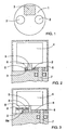
- Fig. 1 shows a shaft 1 of the actuator.
- the shaft 1 of the actuator can be either the control shaft of the actuator or the shaft of the motor.
- Magnets 2 are arranged on the shaft 1.
- the apparatus further comprises a Hall sensor 3, which is arranged at the front of the end of the shaft 1.
- the motor of the actuator is driven, the shaft 1 rotates, whereby the magnets 2 revolve past the Hall sensor 3.
- the Hall sensor 3 generates a pulse.
- the positioning of the actuator is proportional to the rotating motion of the shaft 1: the interval between the pulses corresponds to a certain change in the positioning of the actuator.
- the position of the actuator can thus be defined on the basis of the pulses.
- Fig. 2 shows an actuator in which the magnets 2 are arranged at a shaft 5 of a motor 4.
- the shaft 5 of the motor is provided with a cogwheel 6, in which the magnets 2 are arranged.
- the cogwheels 6 transmit the rotating motion of the shaft 5 of the motor, turning it into the rotating motion of a control shaft 7 of the actuator.
- the rotation of the control shaft 7 adjusts the position of the valve or another actuator in the linear direction, and the adjustment can be effected, for example, by cogwheels or gearing or other shafts.
- the attached drawings do not show the valve nor the gearing nor the other shafts.
- the actuator of the invention can be an actuator known per se, used, for example, in a steam box, head box or moisturizer or some other part of a paper or board machine. It is previously known to use controllable profiling equipment to improve the cross profile variables of the paper web, the equipment being usually divided into control sections crosswise of the web. Each valve, nozzle, etc. that is in the control section of the profiling equipment and affects the variables of paper is controlled by actuators arranged in the section. Any changes effected by the actuators and elements, for example a motion, force, flow, or the like, have an indirect effect on the cross profile characteristics of paper, which include basis weight, moisture, thickness and gloss. The motion, force or some other change mentioned above can be effected in the element by the actuators.
- the actuator of the invention is particularly useful in the control of the steam supply of the steam box of a paper machine.
- the amount of steam supplied from the steam box onto the surface of the web is currently adjusted by the pressure of the supplied steam.
- the pressure is difficult to adjust accurately, and the amount of steam flowing through individual steam nozzles cannot be defined.
- the pressure is defined by an analogue gauge, which is expensive.
- the solution of the invention is cheap and very accurate, since the precise position of the steam control shaft is known.
- the amount of steam is calculated on the basis of pulse data, whereby no separate gauges are needed.
- the amount of steam is adjusted quickly and accurately by means of the pulse data and the control shaft. The invention thus makes it possible to replace expensive gauges, and thereby save money.
- the motor 4 is preferably a synchronous motor with a simple control arrangement.
- the actuator can thus be rendered simple and reliable.
- the Hall sensor 3 and the magnets 2 and the entire actuator can be encased in a housing, whereby they resist wear and also endure well the processing conditions of a paper machine.
- Fig. 3 shows a solution in which the cogwheel 6 of the shaft 5 is also arranged to rotate a detection point wheel 8.
- the magnets 2 are arranged in the detection point wheel 8.
- the cogwheel 6 and the detection point wheel 8 have preferably toothed edges.
- the rim of the cogwheel 6 of the shaft 5 is larger than the rim of a shaft 8a of the detection point wheel 8, and so when shaft 5 rotates, the detection point wheel 8 rotates faster than shaft 5. If the ratio of the rim of the shaft 8a of the detection point wheel 8 to the rim of the cogwheel 6 is 1/20, one turn of shaft 5 corresponds to twenty turns of the detection point wheel 8.
- the motion corresponding to one pulse is 1 micrometer, i.e. the pulses are very frequent, whereby the position of the actuator can be defined very accurately on the basis of the pulses.
- the Hall sensors and magnets can thus vary according to the need.
- a magnet need not necessarily be arranged in conjunction with the shaft, but the Hall sensor can also detect another kind of detection point in the shaft, such as a notch or protrusion or some other asymmetrical point in the shaft, and thereby generate a pulse as the detection point passes the sensor.
- the detection point can consist of non-magnetic material: the Hall sensor detects the passing of such material if the rest of shaft is made of magnetic material.
Landscapes
- Physics & Mathematics (AREA)
- General Physics & Mathematics (AREA)
- Engineering & Computer Science (AREA)
- Human Computer Interaction (AREA)
- Manufacturing & Machinery (AREA)
- Automation & Control Theory (AREA)
- Paper (AREA)
- Linear Motors (AREA)
- Steroid Compounds (AREA)
- Measurement Of Length, Angles, Or The Like Using Electric Or Magnetic Means (AREA)
Abstract
Description
Claims (4)
- An actuator for a paper or board machine and an apparatus for adjusting the position of the actuator in the linear direction comprising a motor (4); a shaft (1, 5, 7) driven by the motor (4), the position of the actuator in the linear direction being adjusted by rotating the shaft (1, 5, 7) by the motor (4); and a sensor which is arranged to measure the rotation of the shaft (1, 5, 7) and to generate a pulse output proportional to the rotation of the shaft (1, 5, 7) to define the position of the actuator in the linear direction, wherein at least one detection point comprising at least one magnet (2) is arranged in conjunction with the shaft (1, 5, 7) and that the apparatus comprises at least one Hall sensor (3), which generates a pulse when the detection point of'the shaft (1, 5, 7) revolves past the Hall sensor (3),
characterized in that said
shaft (5) of the motor (4) is provided with a cogwheel (6) in which magnets (2) are arranged, wherein said cogwheel (6) transmits the rotating motion of the shaft (5) of the motor (4) to a control shaft (7) of the actuator. - An actuator for a paper or board machine and an apparatus for adjusting the position of the actuator in the linear direction comprising a motor (4); a shaft (1, 5, 7) driven by the motor (4), the position of the actuator in the linear direction being adjusted by rotating the shaft (1, 5, 7) by the motor (4); and a sensor which is arranged to measure the rotation of the shaft (1, 5, 7) and to generate a pulse output proportional to the rotation of the shaft (1, 5, 7) to define the position of the actuator in the linear direction, wherein at least one detection point comprising at least one magnet (2) is arranged in conjunction with the shaft (1, 5, 7) and that the apparatus comprises at least one Hall sensor (3), which generates a pulse when the detection point of the shaft (1, 5, 7) revolves past the Hall sensor (3),
characterized in that
said shaft (5) of the motor (4) is provided with a cogwheel (6), which transmits the rotating motion of the shaft (5) of the motor (4) to a control shaft (7) of the actuator, wherein magnets (2) are arranged at a detection point wheel (8) engaged with said cogwheel (6), wherein the rim of said cogwheel (6) is larger than the rim of that part of said detection point wheel (8) which comes into contact with said cogwheel (6) . - An actuator as claimed in claim 1 or 2, characterized in that the Hall sensor (3) is arranged in conjunction with the shaft (5) of the motor (4).
- An actuator as claimed in any one of the preceding claims, characterized in that the motor (4) is a synchronous motor.
Applications Claiming Priority (2)
| Application Number | Priority Date | Filing Date | Title |
|---|---|---|---|
| FI980153A FI108887B (en) | 1998-01-23 | 1998-01-23 | actuator |
| FI980153 | 1998-01-23 |
Publications (2)
| Publication Number | Publication Date |
|---|---|
| EP0932025A1 EP0932025A1 (en) | 1999-07-28 |
| EP0932025B1 true EP0932025B1 (en) | 2004-03-17 |
Family
ID=8550528
Family Applications (1)
| Application Number | Title | Priority Date | Filing Date |
|---|---|---|---|
| EP99660011A Expired - Lifetime EP0932025B1 (en) | 1998-01-23 | 1999-01-20 | Actuator of a paper or board machine |
Country Status (6)
| Country | Link |
|---|---|
| US (1) | US6563305B1 (en) |
| EP (1) | EP0932025B1 (en) |
| AT (1) | ATE262162T1 (en) |
| CA (1) | CA2259859C (en) |
| DE (1) | DE69915525T2 (en) |
| FI (1) | FI108887B (en) |
Families Citing this family (12)
| Publication number | Priority date | Publication date | Assignee | Title |
|---|---|---|---|---|
| EP1275938A3 (en) * | 2001-07-10 | 2003-03-05 | Nidec Corporation | Non-contact type potentiometer |
| DE10134937A1 (en) * | 2001-07-18 | 2003-02-06 | Bosch Gmbh Robert | Gear drive unit with speed detection |
| US6788048B2 (en) * | 2001-10-10 | 2004-09-07 | Stoneridge Control Devices Inc. | Position sensor with reduction gear train |
| DE10321653B3 (en) | 2003-05-14 | 2004-04-29 | Pierburg Gmbh | Final control device, e.g. for combustion engine choke flap, has 2 different polarity magnets in defined positions relative to final control element shaft, functionally connected to contactless switch |
| US20050223832A1 (en) * | 2004-04-02 | 2005-10-13 | Zhihang Li | Actuator using spur gears |
| US20070008063A1 (en) * | 2004-08-13 | 2007-01-11 | Cts Corporation | Rotary actuator with non-contacting position sensor |
| DE102004060714A1 (en) * | 2004-12-17 | 2006-07-06 | Pierburg Gmbh | The switching flap means |
| DE102007062381A1 (en) * | 2007-12-22 | 2009-06-25 | Robert Bosch Gmbh | Hollow shaft motor |
| DE112010000835B4 (en) * | 2009-02-17 | 2014-05-15 | Cts Corporation | Rotary position sensor |
| DE202009006227U1 (en) | 2009-04-30 | 2010-10-21 | Dr. Fritz Faulhaber Gmbh & Co. Kg | Electric actuator |
| DE112014005093T5 (en) * | 2013-11-08 | 2016-08-11 | Ksr Ip Holdings Llc | linear sensor |
| FI127970B (en) * | 2016-03-31 | 2019-06-28 | Tasowheel Systems Oy | METHOD AND EQUIPMENT FOR DETERMINING THE POSITION OF THE DESTINATION AND MEASUREMENT AND CONTROL DEVICE |
Family Cites Families (23)
| Publication number | Priority date | Publication date | Assignee | Title |
|---|---|---|---|---|
| NL254347A (en) * | 1959-09-23 | |||
| US3342070A (en) * | 1964-10-01 | 1967-09-19 | Rockwell Mfg Co | Fluid meter |
| US3981767A (en) * | 1969-12-29 | 1976-09-21 | Westvaco Corporation | Apparatus and method for controlling the stock flow to a paper machine headbox |
| JPS5413919A (en) * | 1977-07-04 | 1979-02-01 | Hitachi Ltd | Preventive controller for torque pulsation |
| JPS6045804B2 (en) * | 1978-02-28 | 1985-10-12 | 日本電気株式会社 | angle detector |
| GB2039079A (en) * | 1978-12-28 | 1980-07-30 | Tlv Co Ltd | Electric motor driving-gear |
| DE3138323A1 (en) * | 1981-09-25 | 1983-04-14 | Siemens AG, 1000 Berlin und 8000 München | Electric motor, especially a DC motor without a commutator |
| US4719419A (en) * | 1985-07-15 | 1988-01-12 | Harris Graphics Corporation | Apparatus for detecting a rotary position of a shaft |
| MX160230A (en) | 1986-02-04 | 1990-01-10 | Beloit Corp | IMPROVEMENTS TO CONTROL VALVE FOR A STEAM BOX OF A PAPER DRYING MACHINE |
| KR910004034B1 (en) * | 1986-09-18 | 1991-06-22 | 미쓰비시전기 주식회사 | Cruise control apparatus |
| DE3726885C2 (en) | 1987-08-12 | 1995-07-13 | Siemens Ag | Actuator |
| US5004981A (en) * | 1988-11-18 | 1991-04-02 | Mitsubishi Jidosha Kogyo Kabushiki Kaisha | Detector device for simultaneously detecting both the direction and number of rotations of rotating member |
| GB2225415A (en) | 1988-11-21 | 1990-05-30 | Aisin Seiki | Fluid control valve |
| DE3903359A1 (en) | 1989-02-05 | 1990-08-09 | Bayerische Motoren Werke Ag | DEVICE FOR DETERMINING THE STEERING WHEEL ANGLE OF A MOTOR VEHICLE |
| FI85731C (en) | 1989-06-01 | 1997-08-20 | Valmet Paper Machinery Inc | Control system in a paper or cardboard machine |
| DE3932177A1 (en) | 1989-09-27 | 1991-04-04 | Philips Patentverwaltung | PRINTING DEVICE |
| JPH0686883B2 (en) | 1990-02-20 | 1994-11-02 | 日機装株式会社 | Bearing monitoring device |
| US5159268A (en) * | 1991-02-21 | 1992-10-27 | Honeywell Inc. | Rotational position sensor with a Hall effect device and shaped magnet |
| US5602472A (en) * | 1993-01-15 | 1997-02-11 | Hughes Electronics | Apparatus and method for determining angular position and rotational speed using a rotating magnet and a directional magnetometer |
| EP0741879B1 (en) * | 1994-01-27 | 1999-08-11 | Hr Textron Inc. | Direct drive servovalve having motor position sensor |
| DE19506938A1 (en) | 1995-02-28 | 1996-08-29 | Bosch Gmbh Robert | Method and device for measuring the angle of a rotatable body |
| US5634373A (en) * | 1995-07-24 | 1997-06-03 | Measurex Devron Inc. | Rotational to linear movement actuator with limiter |
| DE29701674U1 (en) | 1997-01-31 | 1997-04-17 | Werner Riester GmbH & Co. KG Armaturen- und Maschinenantriebe, 79379 Müllheim | Actuator |
-
1998
- 1998-01-23 FI FI980153A patent/FI108887B/en not_active IP Right Cessation
-
1999
- 1999-01-20 US US09/233,544 patent/US6563305B1/en not_active Expired - Lifetime
- 1999-01-20 AT AT99660011T patent/ATE262162T1/en not_active IP Right Cessation
- 1999-01-20 EP EP99660011A patent/EP0932025B1/en not_active Expired - Lifetime
- 1999-01-20 DE DE69915525T patent/DE69915525T2/en not_active Expired - Lifetime
- 1999-01-22 CA CA002259859A patent/CA2259859C/en not_active Expired - Lifetime
Also Published As
| Publication number | Publication date |
|---|---|
| FI980153A0 (en) | 1998-01-23 |
| EP0932025A1 (en) | 1999-07-28 |
| DE69915525D1 (en) | 2004-04-22 |
| ATE262162T1 (en) | 2004-04-15 |
| FI980153L (en) | 1999-07-24 |
| CA2259859A1 (en) | 1999-07-23 |
| FI108887B (en) | 2002-04-15 |
| DE69915525T2 (en) | 2005-03-03 |
| CA2259859C (en) | 2009-05-05 |
| US6563305B1 (en) | 2003-05-13 |
Similar Documents
| Publication | Publication Date | Title |
|---|---|---|
| CA2259859C (en) | Actuator of a paper or board machine | |
| US4719419A (en) | Apparatus for detecting a rotary position of a shaft | |
| CN101263281B (en) | Piston internal combustion engine and method for determining wear of a transmission element arranged between a crankshaft and a camshaft | |
| SE532739C2 (en) | Sensor for touch-free detection of the wear of a brake pad in a vehicle | |
| CA1228412A (en) | Procedure for determining the operating status of an actuating drive of a printing machine and device for implementing the procedure | |
| EP1192408B1 (en) | Method and arrangement for distance measurement | |
| EP1615722B1 (en) | A method and a sensor device for measuring the distance between a stator and an opposing rotor | |
| FI121152B (en) | Method and arrangement for determining rotational motion | |
| CA2259856C (en) | Method and apparatus for defining the position of an actuator | |
| EP0932089B1 (en) | Method for positioning an actuator | |
| US6220158B1 (en) | Rotation-angle measurement for printing presses | |
| US20060011002A1 (en) | Machine tool with dimensional change compensation | |
| US20080030188A1 (en) | Non-contact position sensor | |
| WO2012013857A1 (en) | Arrangement, apparatus and method for determining blade pressure | |
| EP0458899A1 (en) | Two-speed stepper actuator | |
| SU480790A1 (en) | A device for regulating the moisture of the paper web | |
| FI104997B (en) | Device for controlling the position of a control organ | |
| WO2003031297A1 (en) | Method and measuring equipment for determining angular speed difference | |
| WO2011055338A1 (en) | Alignment device for run out measurement apparatus | |
| WO1996022504A1 (en) | Unit equipped with measuring and indicating devices for adjusting position of an actuator | |
| JPH0514854Y2 (en) | ||
| JP2007523329A (en) | Rotary member of a printing press having an encoder and a synthesizer | |
| SU269168A1 (en) | DEVICE FOR REMOTE REGULATION OF PAINT SUPPLY ON A PRINTING MACHINE | |
| SU1475828A1 (en) | Arrangement for adjusting carriage position in case-making machine | |
| SU157886A1 (en) |
Legal Events
| Date | Code | Title | Description |
|---|---|---|---|
| PUAI | Public reference made under article 153(3) epc to a published international application that has entered the european phase |
Free format text: ORIGINAL CODE: 0009012 |
|
| AK | Designated contracting states |
Kind code of ref document: A1 Designated state(s): AT DE FR GB IT SE |
|
| AX | Request for extension of the european patent |
Free format text: AL;LT;LV;MK;RO;SI |
|
| 17P | Request for examination filed |
Effective date: 20000119 |
|
| AKX | Designation fees paid |
Free format text: AT DE FR GB IT SE |
|
| RAP1 | Party data changed (applicant data changed or rights of an application transferred) |
Owner name: NELES PAPER AUTOMATION OY |
|
| RAP1 | Party data changed (applicant data changed or rights of an application transferred) |
Owner name: METSO PAPER AUTOMATION OY |
|
| 17Q | First examination report despatched |
Effective date: 20021008 |
|
| GRAP | Despatch of communication of intention to grant a patent |
Free format text: ORIGINAL CODE: EPIDOSNIGR1 |
|
| GRAS | Grant fee paid |
Free format text: ORIGINAL CODE: EPIDOSNIGR3 |
|
| RAP1 | Party data changed (applicant data changed or rights of an application transferred) |
Owner name: METSO AUTOMATION OY |
|
| GRAA | (expected) grant |
Free format text: ORIGINAL CODE: 0009210 |
|
| AK | Designated contracting states |
Kind code of ref document: B1 Designated state(s): AT DE FR GB IT SE |
|
| PG25 | Lapsed in a contracting state [announced via postgrant information from national office to epo] |
Ref country code: IT Free format text: LAPSE BECAUSE OF FAILURE TO SUBMIT A TRANSLATION OF THE DESCRIPTION OR TO PAY THE FEE WITHIN THE PRESCRIBED TIME-LIMIT;WARNING: LAPSES OF ITALIAN PATENTS WITH EFFECTIVE DATE BEFORE 2007 MAY HAVE OCCURRED AT ANY TIME BEFORE 2007. THE CORRECT EFFECTIVE DATE MAY BE DIFFERENT FROM THE ONE RECORDED. Effective date: 20040317 Ref country code: FR Free format text: LAPSE BECAUSE OF FAILURE TO SUBMIT A TRANSLATION OF THE DESCRIPTION OR TO PAY THE FEE WITHIN THE PRESCRIBED TIME-LIMIT Effective date: 20040317 Ref country code: AT Free format text: LAPSE BECAUSE OF FAILURE TO SUBMIT A TRANSLATION OF THE DESCRIPTION OR TO PAY THE FEE WITHIN THE PRESCRIBED TIME-LIMIT Effective date: 20040317 |
|
| REG | Reference to a national code |
Ref country code: GB Ref legal event code: FG4D |
|
| REF | Corresponds to: |
Ref document number: 69915525 Country of ref document: DE Date of ref document: 20040422 Kind code of ref document: P |
|
| REG | Reference to a national code |
Ref country code: SE Ref legal event code: TRGR |
|
| PLBE | No opposition filed within time limit |
Free format text: ORIGINAL CODE: 0009261 |
|
| STAA | Information on the status of an ep patent application or granted ep patent |
Free format text: STATUS: NO OPPOSITION FILED WITHIN TIME LIMIT |
|
| EN | Fr: translation not filed | ||
| 26N | No opposition filed |
Effective date: 20041220 |
|
| PGFP | Annual fee paid to national office [announced via postgrant information from national office to epo] |
Ref country code: GB Payment date: 20180119 Year of fee payment: 20 Ref country code: DE Payment date: 20180122 Year of fee payment: 20 |
|
| PGFP | Annual fee paid to national office [announced via postgrant information from national office to epo] |
Ref country code: SE Payment date: 20180119 Year of fee payment: 20 |
|
| REG | Reference to a national code |
Ref country code: DE Ref legal event code: R071 Ref document number: 69915525 Country of ref document: DE |
|
| REG | Reference to a national code |
Ref country code: GB Ref legal event code: PE20 Expiry date: 20190119 |
|
| PG25 | Lapsed in a contracting state [announced via postgrant information from national office to epo] |
Ref country code: GB Free format text: LAPSE BECAUSE OF EXPIRATION OF PROTECTION Effective date: 20190119 |