EP0930558A2 - Electronic device and display system employing the same - Google Patents
Electronic device and display system employing the same Download PDFInfo
- Publication number
- EP0930558A2 EP0930558A2 EP99300211A EP99300211A EP0930558A2 EP 0930558 A2 EP0930558 A2 EP 0930558A2 EP 99300211 A EP99300211 A EP 99300211A EP 99300211 A EP99300211 A EP 99300211A EP 0930558 A2 EP0930558 A2 EP 0930558A2
- Authority
- EP
- European Patent Office
- Prior art keywords
- display
- key
- section
- data
- electronic device
- Prior art date
- Legal status (The legal status is an assumption and is not a legal conclusion. Google has not performed a legal analysis and makes no representation as to the accuracy of the status listed.)
- Withdrawn
Links
Images


Classifications
-
- G—PHYSICS
- G06—COMPUTING; CALCULATING OR COUNTING
- G06F—ELECTRIC DIGITAL DATA PROCESSING
- G06F3/00—Input arrangements for transferring data to be processed into a form capable of being handled by the computer; Output arrangements for transferring data from processing unit to output unit, e.g. interface arrangements
- G06F3/01—Input arrangements or combined input and output arrangements for interaction between user and computer
- G06F3/048—Interaction techniques based on graphical user interfaces [GUI]
- G06F3/0487—Interaction techniques based on graphical user interfaces [GUI] using specific features provided by the input device, e.g. functions controlled by the rotation of a mouse with dual sensing arrangements, or of the nature of the input device, e.g. tap gestures based on pressure sensed by a digitiser
- G06F3/0489—Interaction techniques based on graphical user interfaces [GUI] using specific features provided by the input device, e.g. functions controlled by the rotation of a mouse with dual sensing arrangements, or of the nature of the input device, e.g. tap gestures based on pressure sensed by a digitiser using dedicated keyboard keys or combinations thereof
Definitions
- the present invention relates to an electronic device and a display system employing the same, and more particularly to an electronic device capable of being connected to a display device, such as an overhead projector (hereafter referred to as "OHP"), which is utilized for displaying data and explaining operation procedures of the electronic device, and a display system employing the same.
- a display device such as an overhead projector (hereafter referred to as "OHP"
- OHP overhead projector
- the electronic device may be, for example, an electronic function calculator, an electronic notebook, or a personal computer, capable of performing a function-calculating operation.
- the second display device such as a projector often has a large screen because it is used for presentations, and the operator (presenter) operates the personal computer or the like to allow desired images to be displayed.
- Japanese Unexamined Patent Publication No. HEI 08(1996)-275251 discloses a method for transmitting and receiving, at a higher speed and with improved reliability, key data and calculated data by means of infrared communication (serial communication) between an electronic device and a transparency-type display device capable of being connected thereto in displaying on the transparency-type display device the same data as the one displayed on the display section of the electronic device, and a method for processing these data.
- infrared communication serial communication
- Japanese Unexamined Patent Publication No. HEI 06(1994)-35640 discloses a method for transmitting key codes from an electronic device to a display device capable of being connected thereto via a cable (serial communication) in displaying on the display device the same data as the one displayed on the display section of the electronic device.
- the present invention has been made in order to solve these problems, and the purpose thereof is to provide an electronic device, such as a personal computer, that allows a person other than the operator to confirm the operator's operation by displaying, on a display screen of a display device such as a projector connected to the electronic device, an operation data showing how the operator is operating the electronic device, together with an image data displayed on the electronic device.
- an electronic device such as a personal computer
- the present invention provides an electronic device including: a key input section having a plurality of keys; a first display section for displaying a display data; a first display control section for controlling the first display section; a communication section for transmitting the display data to a display device, the display device being separable from the electronic device and including a second display section for displaying the display data and a second display control section for controlling the second display section; a main data memory for storing a main data; a table memory for storing a table of key names in association with the keys; a key name memory for storing, as a key name data, a key name retrieved from the table memory when a key corresponding to the key name is pressed; and a main control section for allowing the first display section and the second display section to display data which are stored in the main data memory and in the key name memory, via the first display control section and the second display control section.
- the present invention provides a display system including an electronic device and a display device, the electronic device including a key input section having a plurality of keys, a first display section for displaying a display data, and a first display control section for controlling the first display section, the display device being separable from the electronic device and including a second display section for displaying the display data and a second display control section for controlling the second display section, the electronic device further including: a communication section for transmitting the display data to the display device; a main data memory for storing a main data; a table memory for storing a table of key names in association with the keys; a key name memory for storing, as a key name data, a key name retrieved from the table memory when a key corresponding to the key name is pressed; and a main control section for allowing the first display section and the second display section to display data which are stored in the main data memory and in the key name memory, via the first display control section and the second display control section.
- the main control section may be capable of selecting whether or not the key name data is to be displayed in the first display section and whether or not the key name data is to be displayed in the second display section.
- the key name memory may store name data of a predetermined number of recently-input keys successively as key name data.
- the main control section may allow at least one of the first display section and the second display section to display, by a scrolling operation, the key name data stored in the key name memory.
- the electronic device may be, for example, an electronic notebook or a personal computer.
- the display device may be, for example, an overhead projector (a display device for overhead projection, hereafter referred to as "OHP") or a plasma display device.
- the first display section may include a liquid crystal display device, a CRT, or the like.
- the second display section may include a liquid crystal panel for OHP, a plasma display panel, or the like.
- the electronic device and the display device may be formed either as an integral body or as separate bodies.
- the key input section may be, for example, a keyboard, a tablet switch, a touch panel, or the like.
- the communication section for transmitting the display data to the display device may be any known wired, wireless, or optical communication device.
- the display data memory for storing the main data and the key name memory for storing key name data may be formed of a RAM.
- the table memory for pre-storing the table of key names in association with the keys may be formed of a ROM.
- the main control section may be formed of a CPU.
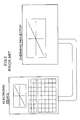
- Fig. 1 is a view schematically illustrating a first embodiment of the present invention.
- the electronic device is a small portable information terminal
- the display device is a projector (OHP) capable of displaying data on a large screen by projection.
- OHP projector
- the present invention should not be limited to this embodiment alone.
- the results corresponding to key operations input from a key input section 14 of the electronic device 11 are displayed on a display section 12 of the electronic device 11 and, at the same time, displayed on a display section 16 of the display device 15.
- key names are also displayed on a key name display area 13 of the display section 12 of the electronic device 11 and, at the same time, displayed on a key name display area 17 of the display section 16 of the display device 15.
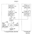
- Fig. 3 is a view showing a circuit construction of the electronic device 11 and the display device 15.
- the electronic device 11 includes a CPU 31, a ROM 32 connected to the CPU 31, a RAM 33, a key input section 14, an I/O port 35, a display control section 36, and a display section 12.
- the display device 15 includes a display control section 38 and a display section 16.
- the RAM 33 is backed up so that the data stored therein are held even if the power supply is turned off.
- the RAM 33 includes a display content storing area 41, a display key name storing area 42, a key code storing area 43, a mode flag storing area 44, a key display position storing area 45, a key code address storing area 46, an area 47 for various calculations, and a user's area 48.
- the display content storing area 41 is an area for storing display contents in order to display the results obtained when the data input from the key input section 34 by the user are processed by the CPU 31.
- the display key name storing area 42 is an area for storing key codes obtained by converting the names of the keys that are operated by the user. These storing areas are in one-to-one correspondence with the display section 12 of the electronic device 11, and also in one-to-one correspondence with the display section 16 of the display device 15.
- the key code storing area 43 is a queue-type area and successively stores the input key codes one after another.
- the mode flag storing area 44 is an area for storing display modes.
- the key display position storing area 45 is an area for storing pointers that indicate the display positions in the key name display areas 13, 17.
- the key code address storing area 46 is an area for storing pointers of the addresses of the key codes that are stored in the key code storing area 43.
- the area 47 for various calculations is an area for performing calculations in response to the user's operations on the key input section 34.
- the user's area 48 is an area for storing user's data, for example, graphs or formulas.
- the ROM 32 is an area that stores various programs for processing data in response to user's key operations and programs for controlling peripheral circuits.
- the ROM 32 includes a font/data 51 for display, a table 52 for converting key codes into display data, a key input program 53, and a display program 54.
- the table 52 stores display data corresponding to key codes. For example, a key X (key code : 0001) 551 corresponds to display bit data 555 "[X]". Also, special keys such as second keys are stored as bit data in the table 52 (554, 558).
- the I/O port 35 (Fig. 3) can switch the display output destination to the display control section 36 of the electronic device 11 or to the display control section 38 of the display device 15.
- the display sections 12, 16 each may be, for example, a transparency-type liquid crystal display.
- Figs. 6 to 9(b) show the mode in which the key names are displayed on the display section 12
- Main the mode in which the key names are displayed on the display section 16
- OHP the mode in which the key names are displayed on the display section 16
- Fig. 6 shows a setting screen for setting the key name display mode from the key input section 14.
- the setting screen is displayed on a portion of the display section 12, where the reverse display portion shows the current state.
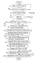
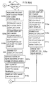
- Figs. 9(a) and 9(b) are flowcharts showing procedures after the mode setting. After a mode change is executed, the mode flag after the change is checked (S22).
- the CPU 31 acquires recent key codes from the key code storing area 43 (S23), and converts the key codes into display data (S20). These display data are expanded in the display key name storing area 42 of the RAM 33 (S21) and, after the output destination of the I/O port 35 is set to the main display (S11), the key names are displayed on the main body (area 13 in the display section 12) (S12). After the output destination of the I/O port 35 is set to the OHP display (S13), the key names are displayed on the OHP (area 17 of the display section 16) (S14), and the mode flag is renewed (S27).
- the CPU 31 acquires recent key codes from the key code storing area 43 (S23a), and converts the key codes into display data (S20a).
- the display key name storing area 42 is cleared (S24).
- the key name display in the area 13 of the main body (display section 12) is cleared (S25).
- the display data converted in S20a are expanded in the display key name storing area 42 of the RAM 33 (S21a).
- the output destination of the I/O port 35 is set to the OHP display (S13a)
- the key names are displayed on the OHP (area 17 in the display section 16) (S14a), and the mode flag is renewed (S27).
- the CPU 31 acquires recent key codes from the key code storing area 43 (S23b), and converts the key codes into display data (S20b) .
- the display key name storing area 42 is cleared (S24a).
- the key name display in the area 17 of the OHP (display section 16) is cleared (S26).
- the display data converted in S20b are expanded in the display key name storing area 42 of the RAM 33 (S21b).
- the output destination of the I/O port 35 is set to the main display (S11b)
- the key names are displayed on the main body (area 13 in the display section 12) (S12a), and the mode flag is renewed (S27).
- the CPU 31 clears the display key name storing area 42 (S24b) in order to clear the key name display in the main body (display section 12) and the OHP (display section 16). Then, after the output destination of the I/O port 35 is set to the OHP display (S13c), the key name display in the area 17 of the OHP (display section 16) is cleared (S26a) . Then, after the output destination of the I/O port 35 is set to the main display (S11c), the key name display in the area 13 of the main body (display section 12) is cleared (S25a), and the mode flag is renewed (S27).
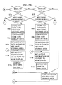
- the CPU 31 waits for key inputs from the key input section 14 (S1). If a key input is present, the CPU 31 checks the mode flag (S3). If the set mode is "Main : ON and OHP : ON" (S4), the CPU 31 checks whether the input key is a key name display scroll key or not (S7). If the input key is not a scroll key, the key code is stored in the key code storing area 43 (S8). In order to display the key code, the CPU 31 converts the key code into a display data (S9) and expands the display data in the display key name storing area 42 (S10).
- the CPU 31 sets the output destination of the I/O port 35 to the main display (S11), and displays the key name on the main body (display section 12) (S12). Then, the CPU 31 sets the output destination of the I/O port 35 to the OHP display (S13), and displays the key name on the OHP (display section 16) (S14). Thereafter, the key display position is renewed (S15), and the key code storage position is renewed (S16). These operations are repeated to display the most recent three key names on the display sections 12, 16, as shown in Fig. 1. The key names are successively renewed.
- the CPU 31 checks whether the input key is a key name display scroll key or not (S7a). If the input key is not a scroll key, the key code is stored in the key code storing area 43 (S8a). In order to display the key code, the CPU 31 converts the key code into a display data (S9a) and expands the display data in the display key name storing area 42 (S10a). Then, the CPU 31 sets the output destination of the I/O port 35 to the OHP display (S13a), and displays the key name on the OHP (display section 16) (S14a). Thereafter, the key display position is renewed (S15), and the key code storage position is renewed (S16).
- the CPU 31 checks whether the input key is a key name display scroll key or not (S7b). If the input key is not a scroll key, the key code is stored in the key code storing area 43 (S8b). In order to display the key code, the CPU 31 converts the key code into a display data (S9b) and expands the display data in the display key name storing area 42 (S10b). Then, the CPU 31 sets the output destination of the I/O port 35 to the main display (S11a), and displays the key name on the main body (display section 12) (S12a). Thereafter, the key display position is renewed (S15), and the key code storage position is renewed (S16).
- the CPU 31 stores the key code in the key code storing area 43 (S8c), and renews the key code storage position (S16). Then, if it is determined in the step S7 that the input key is a key name display scroll key (key for scrolling the key name display), the CPU 31 checks whether the input key is an up-scroll key or not (S17). If the input key is an up-scroll key, the CPU 31 calculates a key code storage position to be obtained by up-scroll of the present key code storage position (S18).
- the CPU 31 calculates a key code storage position to be obtained by down-scroll of the present key code storage position (S19). Thereafter, the CPU 31 converts each key code into a display data (S20), and expands each display data in the display key name storing area 42 (S21). Then, the mode flag is checked (S3) to determine the location to which the flow is to return for each case.
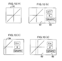
- Figs. 10(a) to 10(d) the display section 12 of the electronic device 11 does not include the key name display area 13 and/or the display section 16 of the display device 15 does not include the key name display area 17.
- the display section 12 and/or the display section 16 can display the portion on the right side of the dotted line of Fig. 10(d) including the key names, as shown by 94 of Fig. 10(c). Also, since the contents in the display content storing area 41 and the contents in the display key name storing area 42 of the RAM 33 are not changed (92, 93), the original display (91) can be restored by a left scroll key of the key input section 14 for displaying an ordinary screen, as shown in Fig. 10(a).
- the electronic device lla is obtained by removing the I/O port 35 from the electronic device 11 shown in Fig. 3 and adding a communication section (105) thereto.
- the display device 15a is obtained by adding a CPU (108), a ROM (109), a RAM (110), and a communication port (111) to the display device 15 shown in Fig. 3.
- the other structures of the electronic device 11a are the same as those shown in Fig. 3.
- the ROM (109) and the RAM (110) of the display device have the same structures as those of the ROM 32 and the RAM 33 of the electronic device 11.
- the communication sections (105, 111) can communicate with each other via cable communication, optical communication, or wireless communication.
- the participants in the lecture meeting can confirm the key operations performed by the presenter without the oral explanation of the presenter. Also, the presenter can confirm his/her own key operations even if the presenter is at a position where it is difficult to see the screen of the display device. Therefore, the presenter can perform a smooth presentation. Also, by successively displaying the key operations, the participants can confirm the key operations without the oral explanation of the presenter, so that the participants can more fully understand the contents of the presentation.
Abstract
Description
Claims (9)
- An electronic device comprising:a key input section having a plurality of keys;a first display section for displaying a display data;a first display control section for controlling the first display section;a communication section for transmitting the display data to a display device, the display device being separable from the electronic device and comprising a second display section for displaying the display data and a second display control section for controlling the second display section;a main data memory for storing a main data;a table memory for storing a table of key names in association with the keys;a key name memory for storing, as a key name data, a key name retrieved from the table memory when a key corresponding to the key name is pressed; anda main control section for allowing the first display section and the second display section to display data which are stored in the main data memory and in the key name memory, via the first display control section and the second display control section.
- The electronic device of claim 1, wherein the main control section selects whether the key name data is to be displayed in the first display section and whether the key name data is to be displayed in the second display section.
- The electronic device of claim 1, wherein the key name memory stores name data of a predetermined number of recently-input keys successively as key name data.
- The electronic device of claim 1, wherein the main control section allows at least one of the first display section and the second display section to display, by a scrolling operation, the key name data stored in the key name memory.
- The electronic device of claim 1, wherein the key name memory stores name data of a predetermined number of recently-input keys successively as key name data, and the main control section successively renews the key name data and allows the first display section and the second display section to display the key name data by a scrolling operation.
- A display system comprising an electronic device and a display device,the electronic device comprising a key input section having a plurality of keys, a first display section for displaying a display data, and a first display control section for controlling the first display section,the display device being separable from the electronic device and comprising a second display section for displaying the display data and a second display control section for controlling the second display section,the electronic device further comprising:a communication section for transmitting the display data to the display device;a main data memory for storing a main data;a table memory for storing a table of key names in association with the keys;a key name memory for storing, as a key name data, a key name retrieved from the table memory when a key corresponding to the key name is pressed; anda main control section for allowing the first display section and the second display section to display data which are stored in the main data memory and in the key name memory, via the first display control section and the second display control section.
- The display system of claim 6, wherein the communication section transmits the display data to the display device via cable communication, optical communication, or wireless communication.
- An electronic device comprisinga key input section having a plurality of keys;a display section for displaying display data;a display control section for controlling said display section, anda data communication section for transmitting the display data to a separate external display device; the device further including means for generating key data identifying a key which has been operated in the key input section, the data communication means being operable to transmit said key data to the external display device for display on a display section thereof.
- An electronic device with its own keyboard and display, the device being operable in conjunction with an external display so that key operation of the device can be shown on the external display.
Applications Claiming Priority (2)
| Application Number | Priority Date | Filing Date | Title |
|---|---|---|---|
| JP712098A JPH11203005A (en) | 1998-01-19 | 1998-01-19 | Electronic equipment |
| JP712098 | 1998-01-19 |
Publications (2)
| Publication Number | Publication Date |
|---|---|
| EP0930558A2 true EP0930558A2 (en) | 1999-07-21 |
| EP0930558A3 EP0930558A3 (en) | 2000-11-15 |
Family
ID=11657231
Family Applications (1)
| Application Number | Title | Priority Date | Filing Date |
|---|---|---|---|
| EP99300211A Withdrawn EP0930558A3 (en) | 1998-01-19 | 1999-01-12 | Electronic device and display system employing the same |
Country Status (3)
| Country | Link |
|---|---|
| US (1) | US6362812B2 (en) |
| EP (1) | EP0930558A3 (en) |
| JP (1) | JPH11203005A (en) |
Families Citing this family (4)
| Publication number | Priority date | Publication date | Assignee | Title |
|---|---|---|---|---|
| US6918768B2 (en) * | 2003-01-31 | 2005-07-19 | Enablearning, Inc. | Computerized system and method for visually based education |
| US7624218B2 (en) * | 2003-10-20 | 2009-11-24 | Dell Products L.P. | System and method for DVI native and docking support |
| JP2008108132A (en) * | 2006-10-26 | 2008-05-08 | Casio Comput Co Ltd | Electronic equipment, projector, electronic equipment control program, projector control program |
| JP6782016B2 (en) * | 2017-08-17 | 2020-11-11 | 有限会社野村環境設計 | Input support device and input support program |
Citations (4)
| Publication number | Priority date | Publication date | Assignee | Title |
|---|---|---|---|---|
| JPS5852737A (en) * | 1981-09-25 | 1983-03-29 | Fuji Facom Corp | Screen information output system |
| JPS63298236A (en) * | 1987-05-28 | 1988-12-06 | Ricoh Co Ltd | Enlarging and projecting device |
| US5250929A (en) * | 1991-07-29 | 1993-10-05 | Conference Communications, Inc. | Interactive overlay-driven computer display system |
| EP0735495A1 (en) * | 1995-03-31 | 1996-10-02 | Casio Computer Co., Ltd. | Display arrangement for electronic calculating apparatus |
Family Cites Families (4)
| Publication number | Priority date | Publication date | Assignee | Title |
|---|---|---|---|---|
| JPH0635640A (en) * | 1992-07-13 | 1994-02-10 | Sharp Corp | Electronic equipment being connectable with dedicated display equipment |
| US5392081A (en) * | 1993-09-29 | 1995-02-21 | Texas Instruments Incorporated | Calculator projection display |
| US5836666A (en) * | 1995-03-31 | 1998-11-17 | Casio Computer Co., Ltd. | Electronic calculating apparatus |
| JP3344641B2 (en) * | 1996-03-07 | 2002-11-11 | シャープ株式会社 | Electronic desk calculator |
-
1998
- 1998-01-19 JP JP712098A patent/JPH11203005A/en active Pending
- 1998-12-16 US US09/212,215 patent/US6362812B2/en not_active Expired - Lifetime
-
1999
- 1999-01-12 EP EP99300211A patent/EP0930558A3/en not_active Withdrawn
Patent Citations (4)
| Publication number | Priority date | Publication date | Assignee | Title |
|---|---|---|---|---|
| JPS5852737A (en) * | 1981-09-25 | 1983-03-29 | Fuji Facom Corp | Screen information output system |
| JPS63298236A (en) * | 1987-05-28 | 1988-12-06 | Ricoh Co Ltd | Enlarging and projecting device |
| US5250929A (en) * | 1991-07-29 | 1993-10-05 | Conference Communications, Inc. | Interactive overlay-driven computer display system |
| EP0735495A1 (en) * | 1995-03-31 | 1996-10-02 | Casio Computer Co., Ltd. | Display arrangement for electronic calculating apparatus |
Non-Patent Citations (2)
| Title |
|---|
| PATENT ABSTRACTS OF JAPAN vol. 007, no. 138 (P-204), 16 June 1983 (1983-06-16) & JP 58 052737 A (FUJI FUAKOMU SEIGIYO KK), 29 March 1983 (1983-03-29) * |
| PATENT ABSTRACTS OF JAPAN vol. 013, no. 127 (P-848), 29 March 1989 (1989-03-29) & JP 63 298236 A (RICOH CO LTD), 6 December 1988 (1988-12-06) * |
Also Published As
| Publication number | Publication date |
|---|---|
| US20010043193A1 (en) | 2001-11-22 |
| JPH11203005A (en) | 1999-07-30 |
| EP0930558A3 (en) | 2000-11-15 |
| US6362812B2 (en) | 2002-03-26 |
Similar Documents
| Publication | Publication Date | Title |
|---|---|---|
| US6411275B1 (en) | Hand-held display device and a method of displaying screen images | |
| US6473006B1 (en) | Method and apparatus for zoomed display of characters entered from a telephone keypad | |
| US20050017946A1 (en) | Portable wireless display device capable of setting operation modes and operation method therefor | |
| JP2000517445A (en) | Touch screen device and method | |
| JP2006155327A (en) | Remote operation system for computer | |
| EP1108241A2 (en) | A hand-held display device and a method of displaying screen images | |
| JPH10260666A (en) | Display controller and recording medium recorded with display control program | |
| JP2000035847A (en) | Multiple screen controllable information processor | |
| EP0930558A2 (en) | Electronic device and display system employing the same | |
| US5757369A (en) | Display system having plurality of display areas | |
| WO2023226842A1 (en) | Information display method and apparatus, electronic device, and readable storage medium | |
| JPH06222867A (en) | Electronic equipment | |
| US8788633B2 (en) | Low bandwidth remote control of an electronic device | |
| JPH02127714A (en) | Information processor | |
| JP2004287169A (en) | Display system, display control method, and display control program | |
| JPH08235119A (en) | Input device | |
| JP2000235447A (en) | Display controller and storage medium | |
| KR20050015897A (en) | Character display method of mobile terminal | |
| JP3467799B2 (en) | Window display system and method | |
| JP2003296029A (en) | Input device | |
| JP3016459B2 (en) | Display device | |
| JPH07162826A (en) | Communication conference system and image display system | |
| JPS58105340A (en) | Character display | |
| JPH10240213A (en) | Video display device | |
| JPH02129689A (en) | Information processor |
Legal Events
| Date | Code | Title | Description |
|---|---|---|---|
| PUAI | Public reference made under article 153(3) epc to a published international application that has entered the european phase |
Free format text: ORIGINAL CODE: 0009012 |
|
| AK | Designated contracting states |
Kind code of ref document: A2 Designated state(s): DE FR GB |
|
| AX | Request for extension of the european patent |
Free format text: AL;LT;LV;MK;RO;SI |
|
| PUAL | Search report despatched |
Free format text: ORIGINAL CODE: 0009013 |
|
| AK | Designated contracting states |
Kind code of ref document: A3 Designated state(s): AT BE CH CY DE DK ES FI FR GB GR IE IT LI LU MC NL PT SE |
|
| AX | Request for extension of the european patent |
Free format text: AL;LT;LV;MK;RO;SI |
|
| RIC1 | Information provided on ipc code assigned before grant |
Free format text: 7G 06F 3/00 A, 7G 06F 3/023 B |
|
| 17P | Request for examination filed |
Effective date: 20010223 |
|
| AKX | Designation fees paid |
Free format text: DE FR GB |
|
| 17Q | First examination report despatched |
Effective date: 20040518 |
|
| STAA | Information on the status of an ep patent application or granted ep patent |
Free format text: STATUS: THE APPLICATION IS DEEMED TO BE WITHDRAWN |
|
| 18D | Application deemed to be withdrawn |
Effective date: 20040929 |