EP0927794B1 - Turning excavator comprising a hydraulic circuit - Google Patents
Turning excavator comprising a hydraulic circuit Download PDFInfo
- Publication number
- EP0927794B1 EP0927794B1 EP97940406A EP97940406A EP0927794B1 EP 0927794 B1 EP0927794 B1 EP 0927794B1 EP 97940406 A EP97940406 A EP 97940406A EP 97940406 A EP97940406 A EP 97940406A EP 0927794 B1 EP0927794 B1 EP 0927794B1
- Authority
- EP
- European Patent Office
- Prior art keywords
- hydraulic
- pump
- boom
- pressure oil
- dipper
- Prior art date
- Legal status (The legal status is an assumption and is not a legal conclusion. Google has not performed a legal analysis and makes no representation as to the accuracy of the status listed.)
- Expired - Lifetime
Links
- 238000010586 diagram Methods 0.000 description 10
- 230000001133 acceleration Effects 0.000 description 9
- 230000007935 neutral effect Effects 0.000 description 4
- 238000009412 basement excavation Methods 0.000 description 2
- 238000010276 construction Methods 0.000 description 2
- 238000004519 manufacturing process Methods 0.000 description 2
- 239000004576 sand Substances 0.000 description 2
- 230000001419 dependent effect Effects 0.000 description 1
- 238000000034 method Methods 0.000 description 1
Images

Classifications
-
- E—FIXED CONSTRUCTIONS
- E02—HYDRAULIC ENGINEERING; FOUNDATIONS; SOIL SHIFTING
- E02F—DREDGING; SOIL-SHIFTING
- E02F9/00—Component parts of dredgers or soil-shifting machines, not restricted to one of the kinds covered by groups E02F3/00 - E02F7/00
- E02F9/20—Drives; Control devices
- E02F9/22—Hydraulic or pneumatic drives
- E02F9/2278—Hydraulic circuits
- E02F9/2282—Systems using center bypass type changeover valves
-
- E—FIXED CONSTRUCTIONS
- E02—HYDRAULIC ENGINEERING; FOUNDATIONS; SOIL SHIFTING
- E02F—DREDGING; SOIL-SHIFTING
- E02F9/00—Component parts of dredgers or soil-shifting machines, not restricted to one of the kinds covered by groups E02F3/00 - E02F7/00
- E02F9/20—Drives; Control devices
- E02F9/22—Hydraulic or pneumatic drives
- E02F9/2221—Control of flow rate; Load sensing arrangements
- E02F9/2239—Control of flow rate; Load sensing arrangements using two or more pumps with cross-assistance
-
- E—FIXED CONSTRUCTIONS
- E02—HYDRAULIC ENGINEERING; FOUNDATIONS; SOIL SHIFTING
- E02F—DREDGING; SOIL-SHIFTING
- E02F9/00—Component parts of dredgers or soil-shifting machines, not restricted to one of the kinds covered by groups E02F3/00 - E02F7/00
- E02F9/20—Drives; Control devices
- E02F9/22—Hydraulic or pneumatic drives
- E02F9/2278—Hydraulic circuits
- E02F9/2292—Systems with two or more pumps
Definitions
- the present invention relates to a turning excavator with a hydraulic circuit system having at least three hydraulic pumps for supplying hydraulic actuators of a turning excavator with pressure oil, wherein working arms consisting of a boom, an arm (a dipper-stick) and a bucket are operated and a turning excavator body is turned by the respective hydraulic actuators.
- Japanese Laid Open Gazette No. Hei 8-134960 discloses a conventional turning excavator provided with a purpose-built hydraulic circuit having a hydraulic pump for it, wherein the circuit can be joined with chosen one of hydraulic circuits for the respective hydraulic actuators like a boom cylinder. Furthermore, Japanese Laid Open Gazette No. Hei 8-113961 discloses a joining circuit including a check valve interposed between a hydraulic circuit for turning the main body and a hydraulic circuit for driving the boom, thereby making the erecting operation of the boom faster than the turning operation of the main body when they are driven simultaneously.
- each hydraulic actuator is supplied with pressure oil from a single hydraulic pump, thereby being too low in quantity of pressure oil to be operated at such a hopeful speed.
- the hydraulic circuit system disclosed in Japanese Laid Open Gazette No. Hei 8-134960 is further provided with such purpose-built circuit for increasing the operation speed, thereby being complicated and expensive.
- the check valve in the joining circuit cannot limit the amount of joined oil flow for restricting the increase of the operation speed.
- more than one of the main body and the working arms are driven simultaneously.
- a horizontal motion of the bucket for horizontal excavation requires the simultaneous erecting operation of the boom and pulling operation of the dipper-stick.
- making the pulling operation of the dipper-stick faster than the erecting operation of the boom is effective.
- JP-A-57205638 describes a hydraulic circuit system for a turning excavator comprising three hydraulic pumps.
- a valve arrangement of this hydraulic circuit system is such that oil delivered from a third pump for driving a turning motor can be supplied to a hydraulic valve for second speed driving of a boom. If the valve for second speed driving of the boom is not switched to a position where the boom is driven in the upward or downward direction, the oil passes the valve and is drained. No acceleration of the operation of the dipper-stick is provided in this prior art valve arrangement.
- JP-A-64090325 discloses another hydraulic circuit system for a turning excavator including three hydraulic pumps, wherein oil supplied from a third pump can be selectively supplied to any of a turning motor, a boom cylinder and a dipper-stick cylinder.
- the oil supply is selectively switched on or off by way of electromagnetic valves positioned within the hydraulic circuit lines to each of the above mentioned elements.
- a hydraulic circuit for a turning excavator according to the present invention is provided with first, second and third hydraulic pumps for supplying pressure oil to respective hydraulic actuators for driving a boom, a dipper-stick, a bucket and a turning main body of the turning excavator.
- an actuator for the boom is supplied with pressure oil from the first and third pumps, an actuator for the dipper-stick from the second and third pumps, an actuator for the bucket from the first pump, and an actuator for the main body from the third pump.
- the third pump's supply of pressure oil to the actuator for the dipper-stick has priority over that for the boom.
- the hydraulic circuit which makes the above mentioned pressure oil supplying patterns by the first, second and third hydraulic pumps thereof, preferentially supplies the actuator for the dipper-stick with pressure oil from the third pump.
- the boom and the main body When the boom and the main body are operated simultaneously, it additionally supplies the actuator for the boom with a part of the pressure oil to the actuator for the main body from the third pump through a branching circuit.
- a main body 4 is rotatably mounted over a crawler type travelling device 5.
- a boom 1 is pivoted at the basic end thereof onto the front end of, the main body 4.
- a dipper-stick 2 is pivoted at the basic end thereof onto the utmost end of the boom 1.
- a bucket 3 is pivoted at the basic end thereof onto the utmost end of the dipper-stick 2.
- the boom 1, dipper-stick 2 and bucket 3, serving as working arms, are driven by hydraulic actuators of a boom cylinder CY1, a dipper-stick cylinder CY2 and a bucket cylinder CY3, respectively.
- the main body 4 is turned about the travelling device 5 by a turning motor M serving as a hydraulic actuator.
- the travelling device 5 is provided with left and right hydraulic travelling motors ML and MR, which can be driven independently to each other.
- a blade 6 is provided on the travelling device 5.
- the blade 6 is vertically moved by a hydraulic cylinder CY4.
- a boom bracket 4a which is disposed on the front end of the main body 4 for pivotally supporting the basic end of the boom 1, is laterally rotated by a hydraulic swinging cylinder CY5 connected to the bottom of the main body 4.
- the boom 1 or dipper-stick 2 is provided with an oil extracting portion for PTO, to which a separate hydraulic driving means can be attached.
- the hydraulic motors ML and MR and cylinders CY4 and CY5 are shown in Fig. 10 .
- the hydraulic circuit system is basically provided with a first hydraulic main pump P1 and a second hydraulic main pump (a second pump) P2 , and a hydraulic auxiliary pump (a third pump) P3, occasionally more than one.
- the first, second and third pumps P1, P2 and P3 are driven by an engine E.
- the first pump P1 is connected to the boom and bucket cylinders CY1 and CY3, the second pump P2 to the dipper-stick cylinder CY2, and the third pump P3 to the turning motor M, through respective hydraulic circuits for supplying the hydraulic actuators with pressure oil.
- the first or third pump P1 or P3 supplies pressure oil as shown in Figs. 3 and 4 .
- joining circuits are extended from the third pump P3 to the boom cylinder CY1 and the dipper-stick cylinder CY2, respectively.
- the pressure oil from the third pump P3 joins that from the first pump P1 as shown in Fig. 1 , thereby supplying the boom cylinder CY1 with the joined increased pressure oil, thereby enabling the erecting motion of the boom 1 to be accelerated.
- the pressure oil from the third pump P3 joins that from the second pump P2 as shown in Fig. 2 , so that the dipper stick cylinder CY2 is supplied with the joined increased pressure oil, thereby moving the dipper-stick 2 swiftly.
- the third pump 3 supplies pressure oil for acceleration of the boom 1 and the dipper-stick 2 unless it is not used for turning the main body 4.
- the boom 1 and the dipper-stick 2 can be accelerated by such simple and low cost hydraulic circuit system which uses the unused hydraulic pump P3 as a pressure oil source for the accelerating operation thereof without an additional hydraulic pump or hydraulic circuit.
- the pressure oil from the third pump P3 is joined to the hydraulic circuit from the second pump P2 to the dipper-stick cylinder CY2 for supplying the dipper-stick cylinder CY2 with the joined pressure oil, thereby accelerating the dipper-stick 2.
- the bucket cylinder CY3 is supplied with pressure oil from the first pump P1
- the dipper-stick cylinder CY2 is supplied with joined pressure oil from the second pump P2 and the third pump P3 in consideration that the operating range of the dipper-stick 2 is larger than that of the bucket 3, thereby accelerating the dipper-stick 2.
- the third pump P3 supplies pressure oil into the turning motor M, which is an original object to be supplied by the third pump P3.
- the pressure oil is supplied from the first pump P1 to the boom cylinder CY1, from the second pump P2 to the dipper-stick cylinder CY2, and from the third pump P3 to the turning motor M, respectively.
- a slow turning of the main body 4 is allowed or preferred, and the boom 1 is desired to be erected as soon as possible.
- the hydraulic circuit between the third pump P3 and the turning motor M is throttled and branches toward the boom cylinder CY1 so as to join the pressure oil from the third pump P3 with the original pressure oil flow from the first pump P1 to the boom cylinder CY1. Due to the addition of the slight pressure oil from the third pump P3 to that for the boom cylinder CY1, the acting speed of the boom 1 is increased so much.
- the turning speed of the main body 4 is reduced because of the throttling of the pressure oil flow for the turning motor M.
- each of hydraulic valves V1 through V8 is neutral and not a pilot pressure Pa for accelerating the boom 1 but a pilot pressure Pb is applied onto a hydraulic accelerating valve V.
- a hydraulic left travelling valve V5L is supplied with the pressure oil from the first pump P1 for driving the left travelling motor ML, and a hydraulic right travelling valve V5R from the second pump P2 for driving the right travelling motor MR.
- the pressure oil from the first pump P1 passing the left travelling valve V5L is supplied to a hydraulic boom valve V1 for controlling the boom cylinder CY1, and further to a hydraulic bucket valve V3 for controlling the bucket cylinder CY3.
- the pressure oil from the second pump P2 passing the right travelling valve V5R is supplied to a hydraulic dipper-stick valve V2 for controlling the dipper-stick cylinder CY2 through a hydraulic swinging valve V7 for controlling the lateral rotation of the boom bracket 4a supporting the basic end of the boom 1, and a hydraulic PTO valve V8.
- the pressure oil from the third pump P3 is supplied to a hydraulic turning valve V4 through a hydraulic blade valve V6 for controlling the hydraulic cylinder for vertical motion of the blade 6, and the accelerating valve V.
- a boom accelerating circuit R1 to the boom valve V1, and a throttling circuit R2 to the turning valve V4.
- the pressure oil from the third pump P3 passing the accelerating valve V (through the blade valve V6) is divided into the boom accelerating circuit R1 and the throttling circuit R2.
- the boom accelerating circuit R1 joins the hydraulic circuit to the boom cylinder CY1.
- the throttling circuit R2 joins the hydraulic circuit to the turning motor M.
- the turning valve V4 is neutral, so that the hydraulic circuit to the boom cylinder CY1 is supplied with the formal quantity of pressure oil from the third pump P3 through the boom accelerating circuit R1 without flowing to the turning valve V4 through the throttling circuit R2, thereby accelerating the boom 1, or making the condition shown in Fig. 1 .
- the pilot pressure Pa is applied only when the boom 1 is accelerated during the individual driving of the boom 1 or during the simultaneous driving of the boom 1 and the main body 4. At all other times, the pilot pressure Pa is not applied so that the pressure oil from the third pump P3 does not flow into either the boom accelerating circuit R1 or the throttling circuit R2. In case of driving the boom cylinder CY1 together with another hydraulic driving means as shown in Fig. 5 or 7 , the boom cylinder CY1 is supplied with only the pressure oil from the first pump P1.
- the turning valve V4 is set in the acting position, thereby shutting off the pressure oil flow to the dipper-stick accelerating circuit R3.
- the dipper-stick cylinder CY2 is supplied with only the pressure oil from the second pump P2, so that the dipper-stick 2 is driven without being accelerated.
- the hydraulic circuit system shown in Fig. 9 such constructed as the above mentioned can make every hydraulic driving pattern of them shown in Figs. 1 through 8 .
- a small excavator employing the system occasionally requires no acceleration or requires the reduction of the increased operation speed.
- the hydraulic circuit system shown in Fig. 10 answers to such requirements.
- the boom accelerating circuit R1 extended from the accelerating valve V can constitute a bleed-off-circuit R1' without joining the hydraulic circuit between the first pump P1 and the boom valve V1, so that the boom 1 is not accelerated, thereby preventing the erecting of the boom 1 from being badly operated at excessive high speed.
- the hydraulic circuit shown in Fig. 10 also limits the increasing speed of the dipper-stick 2.
- the increasing speed of the dipper-stick 2 is limited so as to prevent the dipper-stick 2 from being badly operated at excessive high speed.
- the hydraulic circuit for PTO as shown in Fig. 9 is provided in the hydraulic circuit shown in Fig. 10 , the whole of pressure oil toward the dipper-stick accelerating circuit R3 flows through the PTO accelerating circuit R4.
- the providing of the cut-off circuit R3a enables the the increasing of the PTO operation speed to be limited.
- the above various pressure oil supplying patterns are made by the first and second main pumps P1 and P2 and the third pump P3 without another additional hydraulic pump for acceleration.
- the pressure oil for acceleration thereof can be supplied from the third pump P3, which is not used for turning of the main body, so that the boom or dipper-stick can be operated at an increased speed by such simple and low-cost system, thereby improving the efficiency of working.
- the pressure oil for acceleration of the individual driving of the boom or dipper-stick can be increased, thereby driving it more swiftly.
- the horizontally excavating motion of the bucket for example, can be swift and smooth, and when folding the working arms, the dipper-stick expanded apart from the main body can be pulled swiftly so as to be firstly placed in the safe range of the excavator.
- the dipper-stick can be pulled swiftly into the safe range when the dipper-stick and bucket are folded toward the dipper-stick or in other cases.
- the turning speed of the main body is limited while the operation speed of the boon is increased because of the actuator for the boom additionally supplied with a part of pressure oil flowing between the third pump P3 and the actuator for the main body, so that, when the excavator raises sand and move it to a truck, the erecting motion of the boom is relatively faster than the turning speed of the main body, whereby the excavator can do it swiftly and smoothly.
- the branching circuit to the hydraulic actuator for the boom can communicate with the draining circuit, if the acceleration of the boom is unnecessary in such a case that the hydraulic system is applied on a small turning excavator or so on, the branching circuit is made to be a bleed-off-circuit, so that the actuator for the boom is always supplied with only pressure oil from the first pump P1 without additional pressure oil from the third pump P3, thereby preventing the boom from being badly operated too fast. It means that the hydraulic circuit system can be applied on either of small and large excavators, thereby reducing the manufacturing cost thereof.
- the hydraulic circuit system of the present invention is suitable to a turning excavator having respective hydraulic actuators for driving working arms and turning a main body, the hydraulic actuators being supplied with pressure oil from at least three hydraulic pumps, which has the capacity of accelerating a boom or a dipper-stick for improving efficiency of works.
Landscapes
- Engineering & Computer Science (AREA)
- Mining & Mineral Resources (AREA)
- Civil Engineering (AREA)
- General Engineering & Computer Science (AREA)
- Structural Engineering (AREA)
- Physics & Mathematics (AREA)
- Fluid Mechanics (AREA)
- Operation Control Of Excavators (AREA)
- Fluid-Pressure Circuits (AREA)
Abstract
Description
- The present invention relates to a turning excavator with a hydraulic circuit system having at least three hydraulic pumps for supplying hydraulic actuators of a turning excavator with pressure oil, wherein working arms consisting of a boom, an arm (a dipper-stick) and a bucket are operated and a turning excavator body is turned by the respective hydraulic actuators.
- Conventionally, it is a well-known technique for a turning excavator having a turning excavator body (a main body) and working arms consisting of a boom, a dipper-stick and a bucket to provide the hydraulic circuit system thereof with three hydraulic pumps for supplying hydraulic actuators for respectively driving the boom, the arm, the bucket and the main body with pressure oil, wherein each actuator is supplied with pressure oil by one of the pumps whether the actuators are driven one by one at different times (individually) or more than one of those are driven simultaneously.
- For increasing the operation speed of each of the working arms like the boom, Japanese Laid Open Gazette No.
Hei 8-134960 Hei 8-113961 - Especially in various operations of the boom, the dipper-stick and the bucket of the working arms for excavation, the erecting operation of the boom and the pulling operation of the dipper-stick are hoped to be as swift as possible. However, with respect to the conventional hydraulic system, each hydraulic actuator is supplied with pressure oil from a single hydraulic pump, thereby being too low in quantity of pressure oil to be operated at such a hopeful speed. The hydraulic circuit system disclosed in Japanese Laid Open Gazette No.
Hei 8-134960 - In some working conditions, more than one of the main body and the working arms are driven simultaneously. For example, a horizontal motion of the bucket for horizontal excavation requires the simultaneous erecting operation of the boom and pulling operation of the dipper-stick. In this case, making the pulling operation of the dipper-stick faster than the erecting operation of the boom is effective. However, there is no conventional hydraulic circuit system designed with said case in mind so as to give the dipper-stick priority over the boom when the both are operated simultaneously.
- Supposing the turning excavator raises sand and moves it to a truck, the erecting operation of the boom must be prior to the turning of the main body. The above said conventional hydraulic circuit system of Japanese Laid Open Gazette No.
Hei 8-113961 -
JP-A-57205638 -
JP-A-64090325 - According to the present invention there is provided a turning excavator provided with a hydraulic circuit system as defined in claim 1. Preferred embodiments are defined in the dependent claims.
- A hydraulic circuit for a turning excavator according to the present invention is provided with first, second and third hydraulic pumps for supplying pressure oil to respective hydraulic actuators for driving a boom, a dipper-stick, a bucket and a turning main body of the turning excavator.
- During the individual driving of them, an actuator for the boom is supplied with pressure oil from the first and third pumps, an actuator for the dipper-stick from the second and third pumps, an actuator for the bucket from the first pump, and an actuator for the main body from the third pump.
- For simultaneously driving the boom and the arm, the third pump's supply of pressure oil to the actuator for the dipper-stick has priority over that for the boom.
- During the simultaneous driving of the boom and the dipper-stick, the hydraulic circuit, which makes the above mentioned pressure oil supplying patterns by the first, second and third hydraulic pumps thereof, preferentially supplies the actuator for the dipper-stick with pressure oil from the third pump. When the boom and the main body are operated simultaneously, it additionally supplies the actuator for the boom with a part of the pressure oil to the actuator for the main body from the third pump through a branching circuit.
-
-
Fig. 1 is a diagram showing a pressure oil supplying pattern in a turning excavator having a three pump type hydraulic circuit system according to the present invention, during the individual driving of a boom; -
Fig. 2 is a similar diagram during the individual driving of an arm; -
Fig. 3 is a similar diagram during the individual driving of a bucket; -
Fig. 4 is a similar diagram during the individual driving of a turning main body; -
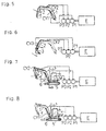
Fig. 5 is a similar diagram during the simultaneous driving of the boom and the dipper-stick; -
Fig. 6 is a similar diagram during the simultaneous driving of the dipper-stick and the bucket; -
Fig. 7 is a similar diagram during the simultaneous driving of the boom, the dipper-stick and the turning main body; -
Fig. 8 is a similar diagram during the simultaneous driving of the boom and the turning main body; -
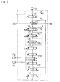
Fig. 9 is a hydraulic circuit diagram of the turning excavator for making the pressure oil supplying patterns shown inFigs. 1 through 8 , and -
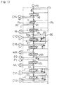
Fig. 10 is a similar hydraulic circuit diagram, wherein a boom accelerating circuit shown inFig. 9 can bleed off and a dipper-stick accelerating circuit shown in the same bleeds off a part of the pressure oil flowing therethrough. - At first, explanation will be given on a general construction of a turning excavator of the present invention. As shown in
Figs. 1 through 8 , a main body 4 is rotatably mounted over a crawlertype travelling device 5. A boom 1 is pivoted at the basic end thereof onto the front end of, the main body 4. A dipper-stick 2 is pivoted at the basic end thereof onto the utmost end of the boom 1. A bucket 3 is pivoted at the basic end thereof onto the utmost end of the dipper-stick 2. The boom 1, dipper-stick 2 and bucket 3, serving as working arms, are driven by hydraulic actuators of a boom cylinder CY1, a dipper-stick cylinder CY2 and a bucket cylinder CY3, respectively. The main body 4 is turned about thetravelling device 5 by a turning motor M serving as a hydraulic actuator. - In addition to the above mentioned hydraulic driving means, the
travelling device 5 is provided with left and right hydraulic travelling motors ML and MR, which can be driven independently to each other. As shown inFig. 4 or others, ablade 6 is provided on thetravelling device 5. Theblade 6 is vertically moved by a hydraulic cylinder CY4. Aboom bracket 4a, which is disposed on the front end of the main body 4 for pivotally supporting the basic end of the boom 1, is laterally rotated by a hydraulic swinging cylinder CY5 connected to the bottom of the main body 4. The boom 1 or dipper-stick 2 is provided with an oil extracting portion for PTO, to which a separate hydraulic driving means can be attached. The hydraulic motors ML and MR and cylinders CY4 and CY5 are shown inFig. 10 . - Next, explanation will be given on a series of pressure oil supplying patterns made by a three pump type hydraulic circuit system in the turning excavator of the present invention having the above various hydraulic driving means in accordance with
Figs. 1 through 8 . At first, the hydraulic circuit system is basically provided with a first hydraulic main pump P1 and a second hydraulic main pump (a second pump) P2 , and a hydraulic auxiliary pump (a third pump) P3, occasionally more than one. The first, second and third pumps P1, P2 and P3 are driven by an engine E. Fundamentally, the first pump P1 is connected to the boom and bucket cylinders CY1 and CY3, the second pump P2 to the dipper-stick cylinder CY2, and the third pump P3 to the turning motor M, through respective hydraulic circuits for supplying the hydraulic actuators with pressure oil. During the individual driving of the bucket 3 or the individual turning of the main body 4, only the first or third pump P1 or P3 supplies pressure oil as shown inFigs. 3 and 4 . - Additionally, joining circuits are extended from the third pump P3 to the boom cylinder CY1 and the dipper-stick cylinder CY2, respectively. During the individual operation of the boom cylinder CY1, the pressure oil from the third pump P3 joins that from the first pump P1 as shown in
Fig. 1 , thereby supplying the boom cylinder CY1 with the joined increased pressure oil, thereby enabling the erecting motion of the boom 1 to be accelerated. During the individual operation of the dipper-stick cylinder CY2, the pressure oil from the third pump P3 joins that from the second pump P2 as shown inFig. 2 , so that the dipper stick cylinder CY2 is supplied with the joined increased pressure oil, thereby moving the dipper-stick 2 swiftly. Thus, the third pump 3 supplies pressure oil for acceleration of the boom 1 and the dipper-stick 2 unless it is not used for turning the main body 4. The boom 1 and the dipper-stick 2 can be accelerated by such simple and low cost hydraulic circuit system which uses the unused hydraulic pump P3 as a pressure oil source for the accelerating operation thereof without an additional hydraulic pump or hydraulic circuit. - In the same construction which supplies pressure oil as the above during the individual driving of the hydraulic actuators, the cases of simultaneous driving of more than one of the hydraulic actuators will be described in accordance with
Figs. 5 through 8 . At first, during the simultaneous driving of the boom 1 and dipper-stick 2 as shown inFig. 5 , while the boom cylinder CY1 is supplied with the pressure oil from the first pump P1, and the dipper-stick cylinder CY2 from the second pump P2, there is such a problem that which cylinder CY1 or CY2 is additionally supplied with the pressure oil from the unused third pump 3. The simultaneous driving of the boom 1 and dipper-stick 2 is required when the working arms are folded. In this situation, the foremost desired operation is that the dipper-stick 2, which has been expanded apart from the main body 4, is pulled swiftly into a safe range, so that priority should be given to the operation of the dipper-stick 2. Accordingly, the pressure oil from the third pump P3 is joined to the hydraulic circuit from the second pump P2 to the dipper-stick cylinder CY2 for supplying the dipper-stick cylinder CY2 with the joined pressure oil, thereby accelerating the dipper-stick 2. - As shown in
Fig. 6 , during the simultaneous driving of the dipper-stick 2 and bucket 3, the bucket cylinder CY3 is supplied with pressure oil from the first pump P1, and the dipper-stick cylinder CY2 is supplied with joined pressure oil from the second pump P2 and the third pump P3 in consideration that the operating range of the dipper-stick 2 is larger than that of the bucket 3, thereby accelerating the dipper-stick 2. - When the main body 4 is turned during the simultaneous driving of the boom 1 and dipper-stick 2, the third pump P3 supplies pressure oil into the turning motor M, which is an original object to be supplied by the third pump P3. In other words, the pressure oil is supplied from the first pump P1 to the boom cylinder CY1, from the second pump P2 to the dipper-stick cylinder CY2, and from the third pump P3 to the turning motor M, respectively.
- During the simultaneous driving of the boom 1 and turning of the main body 4, a slow turning of the main body 4 is allowed or preferred, and the boom 1 is desired to be erected as soon as possible. Then, as shown in
Fig. 8 , the hydraulic circuit between the third pump P3 and the turning motor M is throttled and branches toward the boom cylinder CY1 so as to join the pressure oil from the third pump P3 with the original pressure oil flow from the first pump P1 to the boom cylinder CY1. Due to the addition of the slight pressure oil from the third pump P3 to that for the boom cylinder CY1, the acting speed of the boom 1 is increased so much. The turning speed of the main body 4 is reduced because of the throttling of the pressure oil flow for the turning motor M. - Next, explanation will be given on the hydraulic circuit system shown in
Fig. 9 , which makes the above mentioned various patterns of pressure oil supplying to the hydraulic actuators (the hydraulic cylinders CY1 through CY3 and turning motor M) for driving the working arms (the boom 1, dipper-stick 2 and bucket 3) and for turning the main body 4. In this regard, it is assumed that each of hydraulic valves V1 through V8 is neutral and not a pilot pressure Pa for accelerating the boom 1 but a pilot pressure Pb is applied onto a hydraulic accelerating valve V. - A hydraulic left travelling valve V5L is supplied with the pressure oil from the first pump P1 for driving the left travelling motor ML, and a hydraulic right travelling valve V5R from the second pump P2 for driving the right travelling motor MR. The pressure oil from the first pump P1 passing the left travelling valve V5L is supplied to a hydraulic boom valve V1 for controlling the boom cylinder CY1, and further to a hydraulic bucket valve V3 for controlling the bucket cylinder CY3. The pressure oil from the second pump P2 passing the right travelling valve V5R is supplied to a hydraulic dipper-stick valve V2 for controlling the dipper-stick cylinder CY2 through a hydraulic swinging valve V7 for controlling the lateral rotation of the
boom bracket 4a supporting the basic end of the boom 1, and a hydraulic PTO valve V8. The pressure oil from the third pump P3 is supplied to a hydraulic turning valve V4 through a hydraulic blade valve V6 for controlling the hydraulic cylinder for vertical motion of theblade 6, and the accelerating valve V. - From the accelerating valve V is extended a boom accelerating circuit R1 to the boom valve V1, and a throttling circuit R2 to the turning valve V4. When the pilot pressure Pa is applied onto the accelerating valve V, the pressure oil from the third pump P3 passing the accelerating valve V (through the blade valve V6) is divided into the boom accelerating circuit R1 and the throttling circuit R2. The boom accelerating circuit R1 joins the hydraulic circuit to the boom cylinder CY1. The throttling circuit R2 joins the hydraulic circuit to the turning motor M. Unless the main body 4 is turned, the turning valve V4 is neutral, so that the hydraulic circuit to the boom cylinder CY1 is supplied with the formal quantity of pressure oil from the third pump P3 through the boom accelerating circuit R1 without flowing to the turning valve V4 through the throttling circuit R2, thereby accelerating the boom 1, or making the condition shown in
Fig. 1 . - When the boom 1 is driven and the main body 4 is turned simultaneously, the turning valve V4 is supplied with the reduced pressure oil through the throttling circuit R2, thereby turning the main body 4 slowly. The remaining pressure oil from the third pump P3 flows into the boom accelerating circuit R1. This condition is shown in
Fig. 8 . - The pilot pressure Pa is applied only when the boom 1 is accelerated during the individual driving of the boom 1 or during the simultaneous driving of the boom 1 and the main body 4. At all other times, the pilot pressure Pa is not applied so that the pressure oil from the third pump P3 does not flow into either the boom accelerating circuit R1 or the throttling circuit R2. In case of driving the boom cylinder CY1 together with another hydraulic driving means as shown in
Fig. 5 or 7 , the boom cylinder CY1 is supplied with only the pressure oil from the first pump P1. - During the simultaneous driving of the boom 1 and dipper-stick 2 as shown in
Fig. 5 in the condition that not the pilot pressure Pa but the pilot pressure Pb is applied onto the accelerating valve V, the acceleration of the dipper-stick 2 is prior to that of the boom 1, so that the pressure oil from the third pump P3 through the accelerating valve V passes the neutral turning valve V4 and an dipper-stick accelerating circuit R3 joining the hydraulic circuit between the second pump P2 and the dipper-stick valve V2, whereby the dipper-stick cylinder CY2 is supplied with the joined pressure oil, thereby accelerating the dipper-stick 2. Additionally, a PTO accelerating circuit R4 is interposed between the dipper-stick accelerating circuit R3 and the PTO valve V8. Unless the dipper-stick 2 is driven (when the dipper-stick valve V2 is in neutral), the pressure oil through the dipper-stick accelerating circuit R3 flows into the PTO accelerating circuit R4, thereby enabling a PTO driving device to be driven. - As shown in
Fig. 7 , when the main body 4 is rotated simultaneously with the driving of the boom 1 and dipper-stick 2, the turning valve V4 is set in the acting position, thereby shutting off the pressure oil flow to the dipper-stick accelerating circuit R3. Thus, the dipper-stick cylinder CY2 is supplied with only the pressure oil from the second pump P2, so that the dipper-stick 2 is driven without being accelerated. - The hydraulic circuit system shown in
Fig. 9 such constructed as the above mentioned can make every hydraulic driving pattern of them shown inFigs. 1 through 8 . However, a small excavator employing the system occasionally requires no acceleration or requires the reduction of the increased operation speed. The hydraulic circuit system shown inFig. 10 answers to such requirements. In this case, the boom accelerating circuit R1 extended from the accelerating valve V can constitute a bleed-off-circuit R1' without joining the hydraulic circuit between the first pump P1 and the boom valve V1, so that the boom 1 is not accelerated, thereby preventing the erecting of the boom 1 from being badly operated at excessive high speed. - The hydraulic circuit shown in
Fig. 10 also limits the increasing speed of the dipper-stick 2. In this regard, the dipper-stick accelerating circuit R3, through which the pressure oil from the third pump P3 flows, branches so as to constitute a cut-off circuit R3a having an orifice toward a bleed-off (draining) circuit R5 extended from the dipper-stick valve V2. Accordingly, a part of the pressure oil from the third pump P3 flows into the bleed-off circuit R5 through the cut-off circuit R3a, thereby being bled off. The remaining discharged pressure oil therefrom enters the dipper-stick accelerating circuit R3, so that the dipper-stick cylinder CY2 is supplied with pressure oil less than that in the case shown inFig. 9 . Thus, the increasing speed of the dipper-stick 2 is limited so as to prevent the dipper-stick 2 from being badly operated at excessive high speed. Additionally, when the hydraulic circuit for PTO as shown inFig. 9 is provided in the hydraulic circuit shown inFig. 10 , the whole of pressure oil toward the dipper-stick accelerating circuit R3 flows through the PTO accelerating circuit R4. Thus, the providing of the cut-off circuit R3a enables the the increasing of the PTO operation speed to be limited. - The hydraulic circuit system for a turning excavator such constructed as the above according to the present invention is advantageous as follows:
- The above various pressure oil supplying patterns are made by the first and second main pumps P1 and P2 and the third pump P3 without another additional hydraulic pump for acceleration. Particularly, during the individual driving of the hydraulic actuator for the boom or dipper-stick, the pressure oil for acceleration thereof can be supplied from the third pump P3, which is not used for turning of the main body, so that the boom or dipper-stick can be operated at an increased speed by such simple and low-cost system, thereby improving the efficiency of working.
- When the system is provided with a plurality of the third pumps P3, the pressure oil for acceleration of the individual driving of the boom or dipper-stick can be increased, thereby driving it more swiftly.
- Referring to the simultaneous driving of the boom and arm, since the operation speed of the dipper-stick is higher than that of the boom because of the preferential supplying of the hydraulic actuator for the dipper-stick with pressure oil from the third pump P3, the horizontally excavating motion of the bucket, for example, can be swift and smooth, and when folding the working arms, the dipper-stick expanded apart from the main body can be pulled swiftly so as to be firstly placed in the safe range of the excavator.
- Referring to the simultaneous driving of the bucket and dipper-stick, since the operation speed of the dipper-stick is higher than that of the bucket because of the preferential supplying of the hydraulic actuator for the dipper-stick with pressure oil from the third pump P3, the dipper-stick can be pulled swiftly into the safe range when the dipper-stick and bucket are folded toward the dipper-stick or in other cases.
- Referring to the simultaneous driving of the boom and turning of the main body, the turning speed of the main body is limited while the operation speed of the boon is increased because of the actuator for the boom additionally supplied with a part of pressure oil flowing between the third pump P3 and the actuator for the main body, so that, when the excavator raises sand and move it to a truck, the erecting motion of the boom is relatively faster than the turning speed of the main body, whereby the excavator can do it swiftly and smoothly.
- On the precondition that the branching circuit to the hydraulic actuator for the boom can communicate with the draining circuit, if the acceleration of the boom is unnecessary in such a case that the hydraulic system is applied on a small turning excavator or so on, the branching circuit is made to be a bleed-off-circuit, so that the actuator for the boom is always supplied with only pressure oil from the first pump P1 without additional pressure oil from the third pump P3, thereby preventing the boom from being badly operated too fast. It means that the hydraulic circuit system can be applied on either of small and large excavators, thereby reducing the manufacturing cost thereof.
- Additionally, on the precondition that a part of pressure oil between the third pump P3 and the hydraulic actuator for the dipper-stick is introduced into the draining circuit, even if the acceleration of the dipper-stick is not necessary so much, the amount of pressure oil from the third pump P3 to the actuator for the dipper-stick is limited because of the partly bleeding-off of pressure oil between the third pump P3 and the actuator for the dipper-stick is bled off, so that the increased operation speed of the dipper-stick is limited, thereby thereby preventing the dipper-stick from being badly operated too fast. It means that the hydraulic circuit system can be applied on either of small and large excavators, thereby reducing the manufacturing cost thereof.
- The hydraulic circuit system of the present invention is suitable to a turning excavator having respective hydraulic actuators for driving working arms and turning a main body, the hydraulic actuators being supplied with pressure oil from at least three hydraulic pumps, which has the capacity of accelerating a boom or a dipper-stick for improving efficiency of works.
Claims (5)
- A turning excavator provided with a hydraulic circuit system comprising
a first hydraulic pump (P1), a second hydraulic pump (P2), and a third hydraulic pump (P3); and
a valve arrangement that is operable so that
the first hydraulic pump (P1) supplies pressure oil to hydraulic circuits for driving one of left and right hydraulic travelling motors (ML,MR) and a boom (1),
the second hydraulic pump (P2) supplies pressure oil to hydraulic circuits for driving the other of the left and right hydraulic travelling motors (ML,MR) and a dipper-stick (2),
the third hydraulic pump (P3) supplies pressure oil via a hydraulic valve (V4) to a hydraulic circuit for driving a turning motor (M) for turning an excavator body (4);
wherein said valve arrangement comprises a hydraulic accelerating valve (V) that is switchable between a first position and a second position, wherein,
when said hydraulic accelerating valve (V) is in the first position, the third hydraulic pump (P3) is connected to the hydraulic circuit for driving the dipper-stick (2) via said hydraulic valve (V4) for driving the turning motor (M) and via a hydraulic valve (V2) for driving the dipper-stick (2), for supplying additional pressure oil to the hydraulic circuit for driving the dipper-stick (2), and
when said hydraulic accelerating valve (V) is in the second position, the third hydraulic pump (P3) is connected in parallel to the hydraulic circuit for driving the boom (1) via a boom driving hydraulic circuit (R1) and a hydraulic valve (V1) for driving the boom (1), for supplying additional pressure oil to the hydraulic circuit for driving the boom (1), and to the hydraulic circuit for driving the turning motor (M) via a throttling circuit (R2) and the hydraulic valve (V4) for driving the turning motor (M), for supplying restricted additional pressure oil to the hydraulic circuit for driving the turning motor (M). - The turning excavator according to claim 1, wherein, when only the boom (1) is driven, the hydraulic accelerating valve (V) is in the second position and the hydraulic valve (V1) for driving the boom (1) is operated such that the hydraulic circuit for driving the boom (1) is supplied with pressure oil from the first pump (P1) and with the additional pressure oil from the third pump (P3).
- The turning excavator according to claim 1 or 2, wherein, when only the dipper-stick (2) is driven, the hydraulic accelerating valve (V) is in the first position and the hydraulic valve (V2) for driving the dipper-stick (2) is operated such that the hydraulic circuit for driving the dipper-stick (2) is supplied with pressure oil from the second pump (P2) and with the additional pressure oil from the third pump (P3).
- The turning excavator according to claim 1, 2 or 3, wherein, when the boom (1) and the dipper-stick (2) are simultaneously driven, the hydraulic accelerating valve (V) is in the first position, thereby supplying the hydraulic circuit for driving the boom (1) with pressure oil from the first pump (P1), and the hydraulic circuit for driving the dipper-stick (2) with pressure oil from the second pump (P2) and with the additional pressure oil from the third pump (P3).
- The turning excavator according to any one of claims 1 to 4, wherein, when the bucket (3) and the dipper-stick (2) are simultaneously driven, the hydraulic accelerating valve (V) is in the first position, thereby supplying the hydraulic circuit for driving said bucket (3) with pressure oil from the first hydraulic pump (P1), and the hydraulic circuit for driving the dipper-stick (2) with pressure oil from the second pump (P2) and with the additional pressure oil from the third pump (P3).
Applications Claiming Priority (3)
| Application Number | Priority Date | Filing Date | Title |
|---|---|---|---|
| JP24788396 | 1996-09-19 | ||
| JP24788396A JP3681833B2 (en) | 1996-09-19 | 1996-09-19 | Hydraulic circuit of excavating and turning work machine |
| PCT/JP1997/003288 WO1998012391A1 (en) | 1996-09-19 | 1997-09-18 | Hydraulic circuit for turning excavator |
Publications (3)
| Publication Number | Publication Date |
|---|---|
| EP0927794A1 EP0927794A1 (en) | 1999-07-07 |
| EP0927794A4 EP0927794A4 (en) | 2000-03-22 |
| EP0927794B1 true EP0927794B1 (en) | 2010-11-17 |
Family
ID=17170024
Family Applications (1)
| Application Number | Title | Priority Date | Filing Date |
|---|---|---|---|
| EP97940406A Expired - Lifetime EP0927794B1 (en) | 1996-09-19 | 1997-09-18 | Turning excavator comprising a hydraulic circuit |
Country Status (5)
| Country | Link |
|---|---|
| US (1) | US6330797B1 (en) |
| EP (1) | EP0927794B1 (en) |
| JP (1) | JP3681833B2 (en) |
| DE (1) | DE69740055D1 (en) |
| WO (1) | WO1998012391A1 (en) |
Families Citing this family (43)
| Publication number | Priority date | Publication date | Assignee | Title |
|---|---|---|---|---|
| JPH11287791A (en) | 1998-04-01 | 1999-10-19 | Naohiro Soga | Capillary column |
| ES2178939B1 (en) * | 2000-11-15 | 2004-10-01 | Jose Alfonso Mendoza Aleson | PERFECTED CONCRETE PUMP. |
| JP2002195206A (en) * | 2000-12-28 | 2002-07-10 | Shin Caterpillar Mitsubishi Ltd | Hydraulic circuit for slewing system in working machine |
| KR100518770B1 (en) * | 2003-02-12 | 2005-10-05 | 볼보 컨스트럭션 이키프먼트 홀딩 스웨덴 에이비 | hydraulic system of heavy equipment option device |
| KR100800080B1 (en) * | 2006-08-11 | 2008-02-01 | 볼보 컨스트럭션 이키프먼트 홀딩 스웨덴 에이비 | Hydraulic circuit of construction machinery |
| JP2008115989A (en) * | 2006-11-07 | 2008-05-22 | Hitachi Constr Mach Co Ltd | Hydraulic drive unit for construction machinery |
| JP2008115990A (en) * | 2006-11-07 | 2008-05-22 | Hitachi Constr Mach Co Ltd | Hydraulic drive unit for construction machinery |
| KR100886476B1 (en) * | 2007-03-12 | 2009-03-05 | 볼보 컨스트럭션 이키프먼트 홀딩 스웨덴 에이비 | Hydraulic Circuit for Construction Machinery |
| EP2157245B1 (en) * | 2008-08-21 | 2021-03-17 | Volvo Construction Equipment AB | Hydraulic system for construction equipment |
| JP6015157B2 (en) | 2011-07-01 | 2016-10-26 | コベルコ建機株式会社 | Construction machinery |
| US8966892B2 (en) | 2011-08-31 | 2015-03-03 | Caterpillar Inc. | Meterless hydraulic system having restricted primary makeup |
| US8944103B2 (en) | 2011-08-31 | 2015-02-03 | Caterpillar Inc. | Meterless hydraulic system having displacement control valve |
| US8863509B2 (en) | 2011-08-31 | 2014-10-21 | Caterpillar Inc. | Meterless hydraulic system having load-holding bypass |
| US9057389B2 (en) | 2011-09-30 | 2015-06-16 | Caterpillar Inc. | Meterless hydraulic system having multi-actuator circuit |
| US8966891B2 (en) | 2011-09-30 | 2015-03-03 | Caterpillar Inc. | Meterless hydraulic system having pump protection |
| US9151018B2 (en) | 2011-09-30 | 2015-10-06 | Caterpillar Inc. | Closed-loop hydraulic system having energy recovery |
| US9051714B2 (en) | 2011-09-30 | 2015-06-09 | Caterpillar Inc. | Meterless hydraulic system having multi-actuator circuit |
| US8978374B2 (en) | 2011-10-21 | 2015-03-17 | Caterpillar Inc. | Meterless hydraulic system having flow sharing and combining functionality |
| US8984873B2 (en) | 2011-10-21 | 2015-03-24 | Caterpillar Inc. | Meterless hydraulic system having flow sharing and combining functionality |
| US9068578B2 (en) | 2011-10-21 | 2015-06-30 | Caterpillar Inc. | Hydraulic system having flow combining capabilities |
| US8910474B2 (en) | 2011-10-21 | 2014-12-16 | Caterpillar Inc. | Hydraulic system |
| US8919114B2 (en) | 2011-10-21 | 2014-12-30 | Caterpillar Inc. | Closed-loop hydraulic system having priority-based sharing |
| US8978373B2 (en) | 2011-10-21 | 2015-03-17 | Caterpillar Inc. | Meterless hydraulic system having flow sharing and combining functionality |
| US8893490B2 (en) | 2011-10-21 | 2014-11-25 | Caterpillar Inc. | Hydraulic system |
| US9080310B2 (en) | 2011-10-21 | 2015-07-14 | Caterpillar Inc. | Closed-loop hydraulic system having regeneration configuration |
| US8943819B2 (en) | 2011-10-21 | 2015-02-03 | Caterpillar Inc. | Hydraulic system |
| US8973358B2 (en) | 2011-10-21 | 2015-03-10 | Caterpillar Inc. | Closed-loop hydraulic system having force modulation |
| JP5803587B2 (en) | 2011-11-09 | 2015-11-04 | コベルコ建機株式会社 | Hydraulic circuit for construction machinery |
| JP5859857B2 (en) * | 2012-01-20 | 2016-02-16 | コベルコ建機株式会社 | Hydraulic circuit for construction machinery |
| CN102677734B (en) * | 2012-05-25 | 2015-07-15 | 浙江苏强格液压股份有限公司 | Hydraulic system of excavating machine |
| US9279236B2 (en) | 2012-06-04 | 2016-03-08 | Caterpillar Inc. | Electro-hydraulic system for recovering and reusing potential energy |
| US9290912B2 (en) | 2012-10-31 | 2016-03-22 | Caterpillar Inc. | Energy recovery system having integrated boom/swing circuits |
| JP6004900B2 (en) * | 2012-11-07 | 2016-10-12 | Kyb株式会社 | Hydraulic pressure control device for power shovel |
| JP6012021B2 (en) | 2012-11-07 | 2016-10-25 | Kyb株式会社 | Hydraulic pressure control device for power shovel |
| US9290911B2 (en) | 2013-02-19 | 2016-03-22 | Caterpillar Inc. | Energy recovery system for hydraulic machine |
| JP6196499B2 (en) * | 2013-08-20 | 2017-09-13 | ナブテスコ株式会社 | Multiple directional valve for construction machinery |
| JP6194259B2 (en) | 2014-01-31 | 2017-09-06 | Kyb株式会社 | Work machine control system |
| JP6307292B2 (en) | 2014-01-31 | 2018-04-04 | Kyb株式会社 | Work machine control system |
| JP6286216B2 (en) | 2014-01-31 | 2018-02-28 | Kyb株式会社 | Work machine control system and low pressure selection circuit |
| DE102015211704A1 (en) * | 2015-06-24 | 2016-12-29 | Robert Bosch Gmbh | Valve assembly with at least two pump lines for one pump |
| JP6569852B2 (en) | 2015-06-25 | 2019-09-04 | ヤンマー株式会社 | Hydraulic device |
| JP7121531B2 (en) * | 2018-04-27 | 2022-08-18 | 株式会社小松製作所 | Loading machine control device and control method |
| CN117881857A (en) | 2021-10-29 | 2024-04-12 | 住友建机株式会社 | Excavator |
Family Cites Families (25)
| Publication number | Priority date | Publication date | Assignee | Title |
|---|---|---|---|---|
| NO124443B (en) * | 1970-04-22 | 1972-04-17 | Ingebret Soeyland | |
| US3686862A (en) * | 1971-04-14 | 1972-08-29 | Bucyrus Erie Co | Hydraulic system for single engine truck crane or the like |
| US3922855A (en) * | 1971-12-13 | 1975-12-02 | Caterpillar Tractor Co | Hydraulic circuitry for an excavator |
| US3998053A (en) * | 1976-03-15 | 1976-12-21 | Caterpillar Tractor Co. | Three-pump - three-circuit fluid system of a work vehicle having controlled fluid-combining means |
| US4000616A (en) * | 1976-03-15 | 1977-01-04 | J. I. Case Company | Multi-engine multi-pump hydraulic summating system |
| FR2357764A1 (en) * | 1976-07-06 | 1978-02-03 | Poclain Sa | AT LEAST TWO FLUID MOTOR UNITS |
| US4210061A (en) * | 1976-12-02 | 1980-07-01 | Caterpillar Tractor Co. | Three-circuit fluid system having controlled fluid combining |
| JPS5614607A (en) * | 1979-07-13 | 1981-02-12 | Hitachi Constr Mach Co Ltd | Hydraulic circuit for hydraulic shovel |
| JPS5616736A (en) * | 1979-07-19 | 1981-02-18 | Kobe Steel Ltd | Hydraulic circuit for hydraulic power shovel |
| JPS57134007A (en) * | 1981-02-09 | 1982-08-19 | Ishikawajima Harima Heavy Ind Co Ltd | Fluid pressure circuit of three pumps |
| JPS57140434A (en) * | 1981-02-20 | 1982-08-31 | Kobe Steel Ltd | Oil-pressure circuit for oil-pressure shovel |
| JPS57197336A (en) * | 1981-05-29 | 1982-12-03 | Komatsu Ltd | Oil-pressure circuit for turning excavator |
| JPS57205638A (en) * | 1981-06-09 | 1982-12-16 | Kobe Steel Ltd | Oil-pressure circuit for oil-pressure shovel |
| JPS5815262U (en) * | 1981-07-21 | 1983-01-31 | 城野 晴夫 | Character wheel for counter |
| JPS58118306A (en) * | 1981-12-28 | 1983-07-14 | Daikin Ind Ltd | Hydraulic circuit |
| US4649705A (en) * | 1985-05-14 | 1987-03-17 | Clark Equipment Company | Composite hydraulic system |
| DE3730071A1 (en) * | 1987-09-08 | 1989-03-16 | Walter Hunger | HYDRAULICALLY OPERABLE SUPPORT DEVICE FOR SEMI-TRAILER |
| JPH0745744B2 (en) * | 1987-09-29 | 1995-05-17 | 日立建機株式会社 | Hydraulic drive |
| JPH078601Y2 (en) * | 1987-11-10 | 1995-03-01 | 株式会社クボタ | Backhoe hydraulic circuit |
| US4986075A (en) * | 1988-07-26 | 1991-01-22 | Kubota, Ltd. | Hydraulic circuit for backhoe |
| JPH0751796B2 (en) * | 1989-04-18 | 1995-06-05 | 株式会社クボタ | Backhoe hydraulic circuit |
| JP2564727Y2 (en) * | 1991-03-01 | 1998-03-09 | 油谷重工株式会社 | Hydraulic circuit of small excavator |
| JPH08113961A (en) * | 1994-10-18 | 1996-05-07 | Shin Caterpillar Mitsubishi Ltd | Hydraulic circuit in hydraulic type construction equipment |
| GB9425273D0 (en) * | 1994-12-14 | 1995-02-08 | Trinova Ltd | Hydraulic control system |
| JP3076210B2 (en) * | 1995-02-17 | 2000-08-14 | 日立建機株式会社 | Hydraulic drive for construction machinery |
-
1996
- 1996-09-19 JP JP24788396A patent/JP3681833B2/en not_active Expired - Lifetime
-
1997
- 1997-09-18 EP EP97940406A patent/EP0927794B1/en not_active Expired - Lifetime
- 1997-09-18 DE DE69740055T patent/DE69740055D1/en not_active Expired - Lifetime
- 1997-09-18 WO PCT/JP1997/003288 patent/WO1998012391A1/en not_active Ceased
- 1997-09-18 US US09/254,514 patent/US6330797B1/en not_active Expired - Lifetime
Also Published As
| Publication number | Publication date |
|---|---|
| US6330797B1 (en) | 2001-12-18 |
| JPH1088627A (en) | 1998-04-07 |
| JP3681833B2 (en) | 2005-08-10 |
| DE69740055D1 (en) | 2010-12-30 |
| EP0927794A1 (en) | 1999-07-07 |
| EP0927794A4 (en) | 2000-03-22 |
| WO1998012391A1 (en) | 1998-03-26 |
Similar Documents
| Publication | Publication Date | Title |
|---|---|---|
| US6330797B1 (en) | Hydraulic circuit for turning excavator | |
| KR101932304B1 (en) | Hydraulic drive device for working machine | |
| US4528892A (en) | Hydraulic circuit system for construction machine | |
| WO2005031172A1 (en) | Hydraulic control device of industrial machinery | |
| JP2003148407A (en) | Oil pressure circuit | |
| JPH08240206A (en) | Equipment and method of controlling fluid | |
| CN109563695B (en) | Control valve for excavator and excavator | |
| KR20030008069A (en) | Hydraulic apparatus for controlling complex work mode of travel and front works | |
| US4614475A (en) | Hydraulic circuit system for civil engineering and architectural machinery | |
| JPH0216416B2 (en) | ||
| JP3751973B2 (en) | Hydraulic circuit of excavating and turning work machine | |
| JP3244257B2 (en) | Work machine control circuit of work machine | |
| KR20130057947A (en) | Hydraulic circuit of construction equipment | |
| JP2004324208A (en) | Hydraulic circuit for excavating revolving work machine | |
| JP2635206B2 (en) | Hydraulic circuit structure of excavator | |
| JP3061529B2 (en) | Hydraulic drive for hydraulic excavator with loader front | |
| JP2766365B2 (en) | Hydraulic circuit of excavator | |
| JP3119293B2 (en) | Hydraulic circuit of work machine | |
| KR950005291Y1 (en) | Hydrauric moving system for porclain | |
| JPH09165791A (en) | Hydraulic circuit of work machine | |
| JP6801440B2 (en) | Hydraulic system for construction machinery | |
| KR100188885B1 (en) | Straight driving apparatus for heavy equipment | |
| JP6949783B2 (en) | Work machine hydraulic system | |
| JP4118893B2 (en) | Hydraulic circuit | |
| JPH0637091Y2 (en) | Hydraulic drive for civil engineering and construction machinery |
Legal Events
| Date | Code | Title | Description |
|---|---|---|---|
| PUAI | Public reference made under article 153(3) epc to a published international application that has entered the european phase |
Free format text: ORIGINAL CODE: 0009012 |
|
| 17P | Request for examination filed |
Effective date: 19990211 |
|
| AK | Designated contracting states |
Kind code of ref document: A1 Designated state(s): CH DE FR GB IT LI |
|
| A4 | Supplementary search report drawn up and despatched |
Effective date: 20000203 |
|
| AK | Designated contracting states |
Kind code of ref document: A4 Designated state(s): CH DE FR GB IT LI |
|
| 17Q | First examination report despatched |
Effective date: 20030919 |
|
| 17Q | First examination report despatched |
Effective date: 20030919 |
|
| RAP1 | Party data changed (applicant data changed or rights of an application transferred) |
Owner name: YANMAR CO., LTD. |
|
| GRAP | Despatch of communication of intention to grant a patent |
Free format text: ORIGINAL CODE: EPIDOSNIGR1 |
|
| RTI1 | Title (correction) |
Free format text: TURNING EXCAVATOR COMPRISING A HYDRAULIC CIRCUIT |
|
| GRAS | Grant fee paid |
Free format text: ORIGINAL CODE: EPIDOSNIGR3 |
|
| GRAA | (expected) grant |
Free format text: ORIGINAL CODE: 0009210 |
|
| AK | Designated contracting states |
Kind code of ref document: B1 Designated state(s): CH DE FR GB IT LI |
|
| REG | Reference to a national code |
Ref country code: GB Ref legal event code: FG4D |
|
| REG | Reference to a national code |
Ref country code: CH Ref legal event code: EP |
|
| REF | Corresponds to: |
Ref document number: 69740055 Country of ref document: DE Date of ref document: 20101230 Kind code of ref document: P |
|
| PLBE | No opposition filed within time limit |
Free format text: ORIGINAL CODE: 0009261 |
|
| STAA | Information on the status of an ep patent application or granted ep patent |
Free format text: STATUS: NO OPPOSITION FILED WITHIN TIME LIMIT |
|
| 26N | No opposition filed |
Effective date: 20110818 |
|
| REG | Reference to a national code |
Ref country code: DE Ref legal event code: R097 Ref document number: 69740055 Country of ref document: DE Effective date: 20110818 |
|
| REG | Reference to a national code |
Ref country code: CH Ref legal event code: PL |
|
| PG25 | Lapsed in a contracting state [announced via postgrant information from national office to epo] |
Ref country code: CH Free format text: LAPSE BECAUSE OF NON-PAYMENT OF DUE FEES Effective date: 20110930 Ref country code: LI Free format text: LAPSE BECAUSE OF NON-PAYMENT OF DUE FEES Effective date: 20110930 |
|
| PGFP | Annual fee paid to national office [announced via postgrant information from national office to epo] |
Ref country code: DE Payment date: 20140911 Year of fee payment: 18 |
|
| PGFP | Annual fee paid to national office [announced via postgrant information from national office to epo] |
Ref country code: GB Payment date: 20140917 Year of fee payment: 18 |
|
| PGFP | Annual fee paid to national office [announced via postgrant information from national office to epo] |
Ref country code: IT Payment date: 20140918 Year of fee payment: 18 |
|
| PGFP | Annual fee paid to national office [announced via postgrant information from national office to epo] |
Ref country code: FR Payment date: 20140906 Year of fee payment: 18 |
|
| REG | Reference to a national code |
Ref country code: DE Ref legal event code: R119 Ref document number: 69740055 Country of ref document: DE |
|
| PG25 | Lapsed in a contracting state [announced via postgrant information from national office to epo] |
Ref country code: IT Free format text: LAPSE BECAUSE OF NON-PAYMENT OF DUE FEES Effective date: 20150918 |
|
| GBPC | Gb: european patent ceased through non-payment of renewal fee |
Effective date: 20150918 |
|
| REG | Reference to a national code |
Ref country code: FR Ref legal event code: ST Effective date: 20160531 |
|
| PG25 | Lapsed in a contracting state [announced via postgrant information from national office to epo] |
Ref country code: DE Free format text: LAPSE BECAUSE OF NON-PAYMENT OF DUE FEES Effective date: 20160401 Ref country code: GB Free format text: LAPSE BECAUSE OF NON-PAYMENT OF DUE FEES Effective date: 20150918 |
|
| PG25 | Lapsed in a contracting state [announced via postgrant information from national office to epo] |
Ref country code: FR Free format text: LAPSE BECAUSE OF NON-PAYMENT OF DUE FEES Effective date: 20150930 |