EP0927653B1 - Integral internal reinforcement for a door - Google Patents
Integral internal reinforcement for a door Download PDFInfo
- Publication number
- EP0927653B1 EP0927653B1 EP98119970A EP98119970A EP0927653B1 EP 0927653 B1 EP0927653 B1 EP 0927653B1 EP 98119970 A EP98119970 A EP 98119970A EP 98119970 A EP98119970 A EP 98119970A EP 0927653 B1 EP0927653 B1 EP 0927653B1
- Authority
- EP
- European Patent Office
- Prior art keywords
- door
- integral
- cup
- shaped section
- panel
- Prior art date
- Legal status (The legal status is an assumption and is not a legal conclusion. Google has not performed a legal analysis and makes no representation as to the accuracy of the status listed.)
- Expired - Lifetime
Links
Images

Classifications
-
- B—PERFORMING OPERATIONS; TRANSPORTING
- B60—VEHICLES IN GENERAL
- B60J—WINDOWS, WINDSCREENS, NON-FIXED ROOFS, DOORS, OR SIMILAR DEVICES FOR VEHICLES; REMOVABLE EXTERNAL PROTECTIVE COVERINGS SPECIALLY ADAPTED FOR VEHICLES
- B60J5/00—Doors
- B60J5/04—Doors arranged at the vehicle sides
- B60J5/042—Reinforcement elements
- B60J5/0422—Elongated type elements, e.g. beams, cables, belts or wires
- B60J5/0438—Elongated type elements, e.g. beams, cables, belts or wires characterised by the type of elongated elements
- B60J5/0443—Beams
Definitions
- the invention relates to a vehicle door with integral inner door reinforcement.
- the integral door reinforcement serves to increase the safety of the passengers. She should Prevent door deformation in both frontal and side collisions. In particular, it must be ensured that the door remains open even after an accident can be opened properly. At the same time, the door must not be so stiff that the inertia-related impact of the passenger against the inside of the door the permissible loads and deformation paths are exceeded.
- the object of the invention was to achieve the stated opposite directions in to fulfill optimally.
- the integral door reinforcement is usually an elongated profile with a suitable cross section. Different cross-sectional shapes are used. A such integral door inner reinforcement is for the necessary absorption of the forces Usually connected to the inner door panel, in particular spot welding be used. These reinforcements serve to stiffen the door below the Side window sill.
- No. 4,948,196 describes an inner door reinforcement with its longitudinal axis between the A and B pillars clearly below the window opening on the door hinge has.
- the reinforcement is formed by a rib profile and consists of Ribbed sheets placed in mirror image, the rib axis parallel to Longitudinal axis of the reinforcement runs. In a medium one.
- the area of reinforcement is one Reinforcement plate, bridging the space between the ribs, attached.
- the vehicle door has the features of claim 1.
- a vehicle door has at least one outer, inner and door end plate and an integral door reinforcement, which is designed as an elongated profile and is provided with at least one pot-shaped section.
- the elongated section of the profile into the cup-shaped section.
- the axis of the pot stands approximately perpendicular to the longitudinal axis of the profile.
- the cup-shaped section and its Transition to the elongated profile form a relatively rigid box profile. The arrangement and Geometry of this cup-shaped section between the ends of the elongated integral Interior door reinforcements are adjusted so that the required rigidity is achieved.
- the Form also forms the basis for achieving a defined bending of the belt line, so that the door is not wedged to the frame.
- the door can also be opened Frontal collision can still be opened without tools under normal conditions.
- the integral door interior reinforcement is both connected to the inner panel of the door as well as to the outer panel of the door. Together with the top-shaped section, this connection forms a torsionally rigid load path, which further improves the load distribution in the head-on collision.
- the cup-shaped section is in the area of the in Driving direction seen arranged front door section. This will make the Load distribution in frontal collision further improved.
- the cup-shaped section is at least on one of its sides, which is approximately perpendicular to the floor and on the floor itself Door panels connected.
- the bottom can pass through with the inner panel several spot welds are connected and the front in the direction of travel lying side of the pot-shaped section fastened by several spot welds his. Due to the composite formed by means of several connection points, Area of the cup-shaped section reduces the membrane loads.
- the Pot side surfaces act as tension struts and absorb a large part of the loads. The Conversion of membrane to tensile stresses leads to reduced stresses and Deformations.
- An integral internal door reinforcement is preferred in which a connection is made to the inner panel at the opposite end of an elongated profile and to the outer panel in an intermediate part. This results in an improved power transmission.
- This connection in particular in cooperation with a pot geometry, creates a load path - a diagonal stiffening of the door box in the plan view - which reduces the moment in the door that kinks towards the outside of the vehicle.
- the inner plate can be made relatively soft by the diagonal reinforcement.
- a pot-shaped section can also be considered if e.g. in a substantially U-shaped Cross section of the elongated section at the end of the hinge facing is an end plate running perpendicular to the longitudinal axis e.g. is welded in or if e.g. sections of the U-shaped cross section is processed.
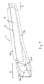
- the invention is illustrated by the embodiment shown schematically in FIG. 1 explained in more detail.
- the integral inner door reinforcement is designed as an elongated profile 1 with a cup-shaped section 2.
- the profile consists essentially of a base surface 3 to which a beveled side surfaces 3a and 3b are connected.
- the cup-shaped section 2 consists essentially of the bottom 2a and the side surfaces 2b (in the Drawing only 2 of the side surfaces are provided with reference symbols).
- the object of the invention is basically achieved by any type of stiffening of the elongated profile.
- the pot-shaped section 2 could also be formed by one or more webs, these webs being connected, for example, to the base surface 3 (for example welded or riveted).
- Such webs would be approximately perpendicular to the base surface 3 and, for example, also substantially perpendicular to the folded side surfaces 3a, 3b, in particular a connection can also be provided with these bent side surfaces.
- the integral inner door reinforcement is connected to the outer sheet approximately at the height of the window cutout.
- a fastening 5 is provided for the door hinge in the front side surface 2b (web) as seen in the direction of travel.
- the integral door interior reinforcement is connected to a sheet facing the occupant (inner sheet).
- the integral door inner reinforcement is fastened to the front door end plate, which is usually designed as an integral part of the inner plate bent from it.
- Fig. 2 shows the hinge area in a horizontal section.
- the integral Inner door reinforcement 1 is with the inner panel 10 or its section 11, which as Door end plate can be seen, connected.
- the inner door reinforcement 5 is provided for the hinge.
- the integral door reinforcement as a direct connection to the hinge is considered special viewed advantageous because this causes the forces acting on the hinge directly into the correspondingly rigid structure. This creates a multiple function for the frontal and side impact, as well as the stiffening with vertical load on the door.
- the integral door reinforcement can be connected to the hinge in done in different ways.
- Fig. 2 is an example with the Section 2b connected nut for receiving a hinge mounting bolt shown.
Description
Die Erfindung betrifft eine Fahrzeugtür mit integraler Türinnenverstärkung.The invention relates to a vehicle door with integral inner door reinforcement.
Die Integrale Türinnenverstärkung dient der erhöhten Sicherheit der Fahrgäste. Sie soll sowohl bei Frontal- als bei seitlichem Zusammenstoß eine Verformung der Tür verhindern. Insbesondere muß dafür gesorgt werden, dass die Tür auch nach einem Unfall noch vorschriftsmäßig geöffnet werden kann. Gleichzeitig darf die Tür nicht so steif gestaltet werden, dass bei dem trägheitsbedingten Aufprall des Fahrgastes gegen die Türinnenseite die zulässigen Lasten und Verformungswege überschritten werden.The integral door reinforcement serves to increase the safety of the passengers. she should Prevent door deformation in both frontal and side collisions. In particular, it must be ensured that the door remains open even after an accident can be opened properly. At the same time, the door must not be so stiff that the inertia-related impact of the passenger against the inside of the door the permissible loads and deformation paths are exceeded.
Aufgabe der Erfindung war es, die genannten an sich gegenläufigen Zielrichtungen in optimaler Weise zu erfüllen.The object of the invention was to achieve the stated opposite directions in to fulfill optimally.
Üblicherweise ist die integrale Türinnenverstärkung ein längliches Profil mit einem geeigneten Querschnitt. Es werden unterschiedliche Querschnittsformen verwendet. Eine derartige integrale Türinnenverstärkung ist für die erforderliche Aufnahme der Kräfte üblicherweise mit dem Türinnenblech verbunden, wobei insbesondere Punktschweißungen verwendet werden. Diese Verstärkungen dienen der Knickaussteifung der Tür unterhalb der Seitenscheibenbrüstung.The integral door reinforcement is usually an elongated profile with a suitable cross section. Different cross-sectional shapes are used. A such integral door inner reinforcement is for the necessary absorption of the forces Usually connected to the inner door panel, in particular spot welding be used. These reinforcements serve to stiffen the door below the Side window sill.
In US 4,948,196 ist eine Türinnenverstärkung beschrieben, die mit ihrer Längsachse zwischen A- und B-Säule deutlich unterhalb des Fensterausschnittes auf das Türscharnier weist. Die Verstärkung wird durch ein Rippenprofil gebildet und besteht aus spiegelbildlich aufeinandergesetzten Rippenblechen, wobei die Rippenachse parallel zur Längsachse der Verstärkung verläuft. In einem mittleren. Bereich der Verstärkung ist eine Verstärkungsplatte, den Zwischenraum zwischen den Rippen überbrückend, angebracht. No. 4,948,196 describes an inner door reinforcement with its longitudinal axis between the A and B pillars clearly below the window opening on the door hinge has. The reinforcement is formed by a rib profile and consists of Ribbed sheets placed in mirror image, the rib axis parallel to Longitudinal axis of the reinforcement runs. In a medium one. The area of reinforcement is one Reinforcement plate, bridging the space between the ribs, attached.
Hierdurch bildet sich in diesem Bereich ein topfförmiger Abschnitt. Dabei bleibt gerade der A-Säulen nahe Bereich im wesentlichen unverstärkt.This creates a pot-shaped section in this area. It stays straight the A-pillars near area essentially unreinforced.
Erfindungsgemäß weist die Fahrzeugtür die Merkmale des Anspruchs 1 auf. Eine solche Fahrzeugtür weist wenigstens ein Außen-, Innen- und Türabschlußblech und eine integrale Türinnenverstärkung auf, die als längliches Profil ausgebildet und mit wenigstens einem topfförmigen Abschnitt versehen ist. Insbesondere mündet der längliche Abschnitt des Profils in den topfförmigen Abschnitt ein. Die Achse des Topfes steht etwa senkrecht auf der Profillängsachse. Der topfförmige Abschnitt und dessen Übergang in das längliche Profil bilden ein relativ steifes Kastenprofil. Die Anordnung und Geometrie dieses topfförmigen Abschnittes zwischen den Enden der länglichen integralen Türinnenverstärkung werden so angepasst, dass die erforderliche Steifigkeit erreicht wird. According to the invention, the vehicle door has the features of claim 1. Such a vehicle door has at least one outer, inner and door end plate and an integral door reinforcement, which is designed as an elongated profile and is provided with at least one pot-shaped section. In particular, the elongated section of the profile into the cup-shaped section. The axis of the pot stands approximately perpendicular to the longitudinal axis of the profile. The cup-shaped section and its Transition to the elongated profile form a relatively rigid box profile. The arrangement and Geometry of this cup-shaped section between the ends of the elongated integral Interior door reinforcements are adjusted so that the required rigidity is achieved.
Grundlage für eine definierte Übertragung von Lasten von der A- auf die B-Säule. Die Form bildet außerdem die Grundlage eine definierte Biegung der Gürtellinie zu erreichen, so daß die Tür nicht mit dem Rahmen verkeilt wird. Die Tür kann auch nach einem Frontalzusammenstoß unter üblichen Bedingen noch ohne Werkzeug geöffnet werden.Basis for a defined transfer of loads from the A to the B pillar. The Form also forms the basis for achieving a defined bending of the belt line, so that the door is not wedged to the frame. The door can also be opened Frontal collision can still be opened without tools under normal conditions.
Nach einer weiter bevorzugten Ausführung wird die integrale Türinnenverstärkung sowohl mit dem Innenblech der Tür als auch mit dem Außenblech der Tür verbunden. Zusammen mit dem toppförmigen Abschnitt bildet diese Verbindung einen torsionssteifen Lastpfad, der die Lastverteilung beim Frontalzusammenstoß weiter verbessert.According to a further preferred embodiment, the integral door interior reinforcement is both connected to the inner panel of the door as well as to the outer panel of the door. Together with the top-shaped section, this connection forms a torsionally rigid load path, which further improves the load distribution in the head-on collision.
Nach einer weiter bevorzugten Ausführung ist der topfförmige Abschnitt im Bereich des in Fahrtrichtung gesehen vorderen Türabschnittes angeordnet. Hierdurch wird die Lastverteilung beim Frontalzusammenstoß weiter verbessert.According to a further preferred embodiment, the cup-shaped section is in the area of the in Driving direction seen arranged front door section. This will make the Load distribution in frontal collision further improved.
Nach einer weiter bevorzugten Ausführung ist der topfförmige Abschnitt wenigstens an einer seiner Seiten, welche etwa senkrecht zum Boden verlaufen und am Boden selber mit Türblechen verbunden. Hierbei kann insbesondere der Boden mit dem Innenblech durch mehrere Punktschweißungen verbunden sein und die in Fahrtrichtung gesehen vorne liegende Seite des topfförmigen Abschnittes durch mehrere Punktschweißungen befestigt sein. Durch den mittels mehrerer Verbindungspunkte gebildeten Verbund werden im Bereich des topfförmigen Abschnittes die Membranbelastungen reduziert. Die Topfseitenflächen wirken als Zugstreben und nehmen einen Großteil der Lasten auf. Die Überführung von Membran- in Zugspannungen führt zu reduzierten Spannungen und Verformungen.According to a further preferred embodiment, the cup-shaped section is at least on one of its sides, which is approximately perpendicular to the floor and on the floor itself Door panels connected. In particular, the bottom can pass through with the inner panel several spot welds are connected and the front in the direction of travel lying side of the pot-shaped section fastened by several spot welds his. Due to the composite formed by means of several connection points, Area of the cup-shaped section reduces the membrane loads. The Pot side surfaces act as tension struts and absorb a large part of the loads. The Conversion of membrane to tensile stresses leads to reduced stresses and Deformations.
Bevorzugt ist eine integrale Türinnenverstärkung bei der an entgegengetzten Ende eines
länglichen Profils eine Verbindung mit dem Innenblech und in einem dazwischenliegenden
Teil mit dem Außenblech erfolgt. Hierdurch wird eine verbesserte Kraftübertragung
erreicht.
Diese Anbindung, insbesondere im Zusammenwirken mit einer Topfgeometrie, bewirkt
einen Lastpfad - in der Draufsicht eine Diagonalversteifung des Türkasten - der das nach
fahrzeugaußen knickende Moment in der Tür reduziert. Bei einer sonst relativ steifen
Gestaltung des Innbleches im Bereich der Rippen eines Insassen kann durch die
Diagonalversteifung das Innblech relativ weich gestaltet werden.An integral internal door reinforcement is preferred in which a connection is made to the inner panel at the opposite end of an elongated profile and to the outer panel in an intermediate part. This results in an improved power transmission.
This connection, in particular in cooperation with a pot geometry, creates a load path - a diagonal stiffening of the door box in the plan view - which reduces the moment in the door that kinks towards the outside of the vehicle. In the case of an otherwise relatively rigid design of the inner plate in the area of the ribs of an occupant, the inner plate can be made relatively soft by the diagonal reinforcement.
Als topfförmiger Abschnitt ist auch anzusehen, wenn z.B. bei einem im wesentlichen U-förmigen Querschnitt des länglichen Abschnittes an dem Ende das dem Scharnier zugewandt ist ein senkrecht zur Längsachse verlaufendes Abschlußblech z.B. eingeschweißt ist oder wenn z.B. abschnittsweise der U-förmige Querschnitt verbeitert ist.A pot-shaped section can also be considered if e.g. in a substantially U-shaped Cross section of the elongated section at the end of the hinge facing is an end plate running perpendicular to the longitudinal axis e.g. is welded in or if e.g. sections of the U-shaped cross section is processed.
Die Erfindung wird anhand des in Fig. 1 schematisch dargestellten Ausführungsbeispieles näher erläutert.The invention is illustrated by the embodiment shown schematically in FIG. 1 explained in more detail.
Die integrale Türinnenverstärkung ist als längliches Profil 1 mit einem topfförmigen
Abschnitt 2 ausgebildet. Im übrigen besteht das Profil im wesentlichen aus einer
Basisfläche 3 an die sich eine abgekantete Seitenflächen 3a und 3b anschließen. Der
topfförmige Abschnitt 2 besteht im wesentlichen aus Boden 2a und den Seitenflächen 2b
(in der
Zeichnung sind nur 2 der Seitenflächen mit Bezugszeichen versehen). Die Aufgabe der
Erfindung wird grundsätzlich durch jede Art der Versteifung des länglichen Profils gelöst.
So könnte der topfförmige Abschnitt 2 z.B. auch durch einen oder mehrere Stege gebildet
werden, wobei diese Stege z.B. mit der Basisfläche 3 verbunden sind (z.B. verschweißt
oder vernietet). Derartige Stege würden in etwa senkrecht zur Basisfläche 3 stehen und z.B.
auch im wesentlichen senkrecht zu den abgekanteten Seitenflächen 3a, 3b wobei
insbesondere eine Verbindung auch mit diesen abgekanteten Seitenflächen vorgesehen sein
kann. Im Bereich der abgekanteten Seitenfläche 3a ist die integrale Türinnenverstärkung
etwa in Höhe des Fensterausschnittes mit dem Außenblech verbunden. Unterhalb der
Flucht der Linie 4 ist in der in Fahrtrichtung gesehen vorderen Seitenfläche 2b (Steg) eine
Befestigung 5 für das Türscharnier vorgesehen.. Im Bereich des Bodens 2a, sowie am
entgegen gesetzten Ende 7 (bei einem Steg wäre dies entsprechend die Basisfläche 3) ist
die integrale Türinnenverstärkung mit einem dem Insassen zugewandten Blech verbunden
(Innenblech). Im Bereich der Scharnierbefestigung 5 (vordere Seitenfläche 2b bzw. Steg)
ist die integrale Türinnenverstärkung an dem vorderen Türabschlußblech, welches
üblicherweise als ein integraler Bestandteil des Innenbleches von diesem abgekantet
ausgebildet ist, befestigt. The integral inner door reinforcement is designed as an elongated profile 1 with a cup-
Drawing only 2 of the side surfaces are provided with reference symbols). The object of the invention is basically achieved by any type of stiffening of the elongated profile. For example, the pot-
Fig. 2 zeigt den Scharnierbereich in einem Horizontalschnitt. Die integrale
Türinnenverstärkung 1 ist mit dem Innenblech 10 bzw. dessen Abschnitt 11, welcher als
Türabschlußblech zu sehen ist, verbunden. Im Bereich der Stegfläche 2b der integralen
Türinnenverstärkung ist die Befestigung 5 für das Scharnier vorgesehen. Die Verwendung
der intergralen Tütverstärkung als direkte Anbindung an das Scharnier wird als besonders
vorteilhaft angesehen weil hierdurch die am Scharnier wirkenden Kräfte direkt in die
entsprechend steife Struktur eingeleitet werden. Hierdurch wird eine Mehrfachfunktion für
den Frontal- und Seitenstoß, sowie die Versteifung bei vertikaler Last auf die Tür erreicht.
Die Anbindung der integralen Türinnenverstärkung an das Scharnier kann in
unterschiedlichster Weise erfolgen. In Fig. 2 ist lediglich beispielhaft eine mit dem
Abschnitt 2b verbundene Mutter zur Aufnahme eines Scharnierbefestigungsbolzens
dargestellt.Fig. 2 shows the hinge area in a horizontal section. The integral
Inner door reinforcement 1 is with the inner panel 10 or its
Claims (7)
- Vehicle door having an integral inside door reinforcement for a defined transmission of loads from the A-pillar to the B-pillar, and having door panels which have at least one outside panel, at least one inside panel and at least one door end panel which runs essentially perpendicularly with respect to the outside panel and inside panel, and the integral inside door reinforcement being designed as an elongated profile (1) and being provided with at least one cup-shaped section (2), characterized in that a cup-shaped section (2) is arranged in the region of the front door section, as seen in the direction of travel, and the inside door reinforcement points with its longitudinal direction towards the door hinge approximately level with the window cutout.
- Vehicle door having an integral door reinforcement according to Claim 1, characterized in that there is a first connection (2a, 7) to the inside panel and a second connection (3a) to the outside panel.
- Vehicle door having an integral inside door reinforcement according to Claim 1 or 2, characterized in that a connection to a door panel takes place in the form of a plurality of connecting points in the region of the cup-shaped section (2).
- Vehicle door having an integral inside door reinforcement according to one of Claims 1 to 3, characterized in that the cup-shaped section is connected at at least one side section and at the bottom to one or more of the door panels.
- Vehicle door having an integral inside door reinforcement according to one of Claims 1 to 4, characterized in that the bottom (2a) of the cup-shaped section (2) and that end (7) of the elongated profile (1) which is opposite thereto are connected to the inside door panel.
- Vehicle door having an integral inside door reinforcement according to one of Claims 1 to 5, characterized in that a hinge fastening (5) is connected to the cup-shaped section (2).
- Vehicle door having an integral inside door reinforcement according to Claim 6, characterized in that the hinge fastening (5) is arranged on that end surface (2b) of the cup-shaped section (2) which is approximately perpendicular with respect to the longitudinal axis.
Applications Claiming Priority (2)
| Application Number | Priority Date | Filing Date | Title |
|---|---|---|---|
| DE19748970 | 1997-11-06 | ||
| DE19748970A DE19748970B4 (en) | 1997-11-06 | 1997-11-06 | Integral door interior reinforcement |
Publications (2)
| Publication Number | Publication Date |
|---|---|
| EP0927653A1 EP0927653A1 (en) | 1999-07-07 |
| EP0927653B1 true EP0927653B1 (en) | 2002-09-11 |
Family
ID=7847747
Family Applications (2)
| Application Number | Title | Priority Date | Filing Date |
|---|---|---|---|
| EP98119970A Expired - Lifetime EP0927653B1 (en) | 1997-11-06 | 1998-10-22 | Integral internal reinforcement for a door |
| EP98961072A Expired - Lifetime EP1027223B1 (en) | 1997-11-06 | 1998-11-06 | Integral inside door reinforcement |
Family Applications After (1)
| Application Number | Title | Priority Date | Filing Date |
|---|---|---|---|
| EP98961072A Expired - Lifetime EP1027223B1 (en) | 1997-11-06 | 1998-11-06 | Integral inside door reinforcement |
Country Status (7)
| Country | Link |
|---|---|
| US (1) | US6302473B1 (en) |
| EP (2) | EP0927653B1 (en) |
| CN (1) | CN1105044C (en) |
| DE (2) | DE19748970B4 (en) |
| ES (1) | ES2207017T3 (en) |
| RU (1) | RU2226468C2 (en) |
| WO (1) | WO1999024278A1 (en) |
Families Citing this family (41)
| Publication number | Priority date | Publication date | Assignee | Title |
|---|---|---|---|---|
| DE19950656A1 (en) * | 1999-10-21 | 2001-05-10 | Porsche Ag | Vehicle door, in particular motor vehicle door |
| JP2001334955A (en) * | 2000-05-29 | 2001-12-04 | Toyota Motor Corp | Reinforcing structure of vehilce door |
| US6508035B1 (en) * | 2000-07-25 | 2003-01-21 | Alcoa Inc. | Ultra-lightweight thin sliding door for a vehicle |
| ATE230684T1 (en) * | 2000-08-19 | 2003-01-15 | Benteler Werke Ag | SIDE IMPACT SUPPORT |
| DE10042409A1 (en) * | 2000-08-30 | 2002-03-28 | Porsche Ag | Structure for a motor vehicle |
| US6398289B1 (en) * | 2000-10-19 | 2002-06-04 | Benteler Automobiltechnik Gmbh & Co. Kg | Side impact beam |
| DE10063417A1 (en) * | 2000-12-19 | 2002-07-04 | Wagon Automotive Gmbh | Lightweight door for motor vehicles |
| SE0100356L (en) * | 2001-02-02 | 2002-01-29 | Ssab Hardtech Ab | Inner panel for a vehicle door |
| US8434230B2 (en) * | 2001-02-09 | 2013-05-07 | Gestamp Hardtech Ab | Method to make a vehicle door |
| SE518503C2 (en) * | 2001-02-09 | 2002-10-15 | Ssab Hardtech Ab | Vehicle door with seat belt and side impact protection beam made in one piece with the door frame, as well as ways to manufacture such a |
| DE10114384B4 (en) * | 2001-03-23 | 2008-04-10 | Audi Ag | Motor vehicle door |
| SE523371C2 (en) | 2001-08-31 | 2004-04-13 | Accra Teknik Ab | Beam |
| JP3632850B2 (en) * | 2002-01-16 | 2005-03-23 | 本田技研工業株式会社 | Automotive door |
| SE523365C2 (en) * | 2002-08-08 | 2004-04-13 | Ssab Hardtech Ab | Vehicle |
| FR2846924B1 (en) * | 2002-11-12 | 2006-12-15 | Arvinmeritor Light Vehicle Sys | ANTI-INTRUSION ASSEMBLY |
| DE102004018745B4 (en) * | 2004-04-17 | 2008-05-08 | Dr.Ing.H.C. F. Porsche Ag | Body structure of a passenger car, especially a convertible |
| DE102004057222B4 (en) * | 2004-11-26 | 2008-03-20 | Audi Ag | Door hinge for motor vehicle and vehicle door |
| US20070084130A1 (en) * | 2005-10-19 | 2007-04-19 | Gaustad Mark D | Channel Assembly for a Vehicle Window |
| JP4640127B2 (en) * | 2005-11-15 | 2011-03-02 | 日産自動車株式会社 | Door waist structure |
| US20070119101A1 (en) * | 2005-11-29 | 2007-05-31 | Ford Global Technologies, Llc | Internal reinforcement structure for automotive vehicle door panels |
| JP4240064B2 (en) * | 2006-06-09 | 2009-03-18 | トヨタ自動車株式会社 | Vehicle door structure |
| CN101121419B (en) * | 2006-08-11 | 2010-10-27 | 上海华普汽车有限公司 | Automobile threshold |
| JP4355958B2 (en) * | 2006-11-21 | 2009-11-04 | いすゞ自動車株式会社 | Vehicle door structure |
| JP4265660B2 (en) * | 2007-02-01 | 2009-05-20 | トヨタ自動車株式会社 | Vehicle door structure |
| DE102007032651A1 (en) * | 2007-07-13 | 2009-01-15 | Dr. Ing. H.C. F. Porsche Aktiengesellschaft | Motor vehicle door |
| DE102007052618A1 (en) * | 2007-11-05 | 2009-05-07 | GM Global Technology Operations, Inc., Detroit | Device for guiding a fall washer |
| DE102008038845A1 (en) * | 2008-08-13 | 2010-02-18 | Daimler Ag | Mirror reinforcement element for reinforcing support part in e.g. driver door of passenger car, has component region provided with fastening region connectable with side impact protection carrier of door of passenger car |
| CN101812959B (en) * | 2010-05-06 | 2012-10-24 | 江苏大红成莱宝驰机车制造有限公司 | Reinforced type glass steel automobile door plate |
| JP5692776B2 (en) * | 2010-06-11 | 2015-04-01 | シロキ工業株式会社 | Vehicle door frame |
| KR101338775B1 (en) * | 2011-12-07 | 2013-12-06 | 현대자동차주식회사 | Door Impact Beam Unit for 2 - Door Vehicle |
| US8640427B2 (en) | 2012-03-30 | 2014-02-04 | Door Components, Inc. | Sound insulating door |
| JP5949479B2 (en) * | 2012-11-14 | 2016-07-06 | マツダ株式会社 | Door mirror mounting structure |
| DE102012025392B3 (en) * | 2012-12-24 | 2014-02-20 | Audi Ag | Covering device for a with a locking wedge module in a connection of a vehicle door with a side wall frame of a vehicle body causing releasable coupling bringable holding jaw module |
| JP6137146B2 (en) * | 2014-11-27 | 2017-05-31 | トヨタ自動車株式会社 | Vehicle side structure |
| FR3035033B1 (en) * | 2015-04-16 | 2017-04-07 | Renault Sas | DOOR STRUCTURE WITH A LOCAL CLOSURE MEMBER OF THE BANDEAU REINFORCEMENT PROFILE SECTION |
| JP6373938B2 (en) * | 2016-11-17 | 2018-08-15 | 本田技研工業株式会社 | Door structure |
| KR20180068108A (en) * | 2016-12-13 | 2018-06-21 | 현대자동차주식회사 | Door structure for vehicle |
| US10479411B2 (en) * | 2018-01-31 | 2019-11-19 | Toyota Motor Engineering & Manufacturing North America, Inc. | Structurally reinforced vehicle body |
| JP7234523B2 (en) * | 2018-07-20 | 2023-03-08 | スズキ株式会社 | vehicle side structure |
| KR20210029433A (en) | 2019-09-06 | 2021-03-16 | 현대자동차주식회사 | variable type back beam and, method for varying of variable type back beam by the inflator at impact time |
| WO2022010826A1 (en) * | 2020-07-06 | 2022-01-13 | Magna International Inc. | Automotive side door structure |
Family Cites Families (20)
| Publication number | Priority date | Publication date | Assignee | Title |
|---|---|---|---|---|
| DE2127724C3 (en) * | 1971-06-04 | 1975-06-05 | Ford-Werke Ag, 5000 Koeln | Vehicle door, in particular for passenger vehicles |
| US3882970A (en) * | 1973-10-15 | 1975-05-13 | Dow Chemical Co | Impact absorbing structure |
| GB1453353A (en) * | 1974-01-10 | 1976-10-20 | Chrysler Uk | Vehicle doors |
| JPS5688885U (en) * | 1979-12-10 | 1981-07-16 | ||
| US4306381A (en) * | 1980-02-11 | 1981-12-22 | The Budd Company | Plastic door for an automobile |
| EP0208188B1 (en) * | 1985-06-25 | 1989-10-11 | Mazda Motor Corporation | Vehicle door structure having plastic door panel |
| CA1319266C (en) * | 1986-04-24 | 1993-06-22 | Pacifico V. Manalastas | Coatings with sulfonated polymers |
| US4850636A (en) * | 1986-09-19 | 1989-07-25 | The Dow Chemical Company | Cartridge assmebly for a vehicle door, a vehicle door shell and a door assembly |
| JPS641116U (en) * | 1987-06-23 | 1989-01-06 | ||
| US4845894A (en) * | 1987-08-25 | 1989-07-11 | The Budd Company | Method of mounting an outer skin to an inner panel of a vehicle door |
| SE501812C2 (en) * | 1992-09-25 | 1995-05-22 | Plannja Hardtech Ab | Safety bar in vehicle |
| DE4234799B4 (en) * | 1992-10-15 | 2005-06-30 | Adam Opel Ag | To be arranged on a vehicle longitudinal side between two supporting, vertical pillars motor vehicle door |
| US5314228A (en) * | 1993-03-16 | 1994-05-24 | Atlantic Research Corporation | Vehicle side impact intrusion barrier |
| US5505024A (en) * | 1993-11-22 | 1996-04-09 | Chrysler Corporation | Vehicle door assembly |
| US5364157A (en) * | 1993-12-27 | 1994-11-15 | Ford Motor Company | Reinforced cargo door assembly |
| DE4421934A1 (en) * | 1994-06-23 | 1996-01-04 | Ford Werke Ag | Metallic profile to reinforce a motor vehicle door |
| US5536060A (en) * | 1995-02-17 | 1996-07-16 | General Motors Corporation | Reinforced vehicle door |
| US5908216A (en) * | 1995-12-22 | 1999-06-01 | Joalto Design, Inc. | Side intrusion beam with four points of connection |
| DE19647334B4 (en) * | 1996-11-15 | 2004-07-15 | Benteler Ag | Side impact beam for a passenger car |
| DE19654376B4 (en) * | 1996-12-24 | 2005-08-04 | Thyssen Krupp Automotive Gmbh | Side impact beams for vehicle doors |
-
1997
- 1997-11-06 DE DE19748970A patent/DE19748970B4/en not_active Expired - Lifetime
-
1998
- 1998-10-22 DE DE59805501T patent/DE59805501D1/en not_active Expired - Lifetime
- 1998-10-22 EP EP98119970A patent/EP0927653B1/en not_active Expired - Lifetime
- 1998-11-06 US US09/530,922 patent/US6302473B1/en not_active Expired - Fee Related
- 1998-11-06 ES ES98961072T patent/ES2207017T3/en not_active Expired - Lifetime
- 1998-11-06 RU RU2000114820/11A patent/RU2226468C2/en not_active IP Right Cessation
- 1998-11-06 WO PCT/DE1998/003252 patent/WO1999024278A1/en active IP Right Grant
- 1998-11-06 EP EP98961072A patent/EP1027223B1/en not_active Expired - Lifetime
- 1998-11-06 CN CN98810817A patent/CN1105044C/en not_active Expired - Fee Related
Also Published As
| Publication number | Publication date |
|---|---|
| ES2207017T3 (en) | 2004-05-16 |
| DE59805501D1 (en) | 2002-10-17 |
| DE19748970B4 (en) | 2005-12-08 |
| EP0927653A1 (en) | 1999-07-07 |
| WO1999024278A1 (en) | 1999-05-20 |
| EP1027223A1 (en) | 2000-08-16 |
| US6302473B1 (en) | 2001-10-16 |
| RU2226468C2 (en) | 2004-04-10 |
| EP1027223B1 (en) | 2003-10-22 |
| CN1278216A (en) | 2000-12-27 |
| CN1105044C (en) | 2003-04-09 |
| DE19748970A1 (en) | 1999-05-20 |
Similar Documents
| Publication | Publication Date | Title |
|---|---|---|
| EP0927653B1 (en) | Integral internal reinforcement for a door | |
| EP1525132B1 (en) | Floor-supporting arrangement in motor vehicles | |
| DE19531982B4 (en) | Body structure for a motor vehicle | |
| EP2547574B1 (en) | Front end of a vehicle | |
| DE102013215793A1 (en) | vehicle body | |
| DE102016209186B3 (en) | Body structure for a motor vehicle | |
| DE102009004886B4 (en) | body structure | |
| EP1840006B1 (en) | Vehicle body with cross member structure for the seating area in the vehicle | |
| EP2042408B1 (en) | Roll-over device | |
| EP1525133B1 (en) | Floor-stiffening structure in motor vehicles | |
| DE19853338B4 (en) | Arrangement with a front pillar for a body frame of a motor vehicle | |
| DE102006015416A1 (en) | Chassis especially for roadster has a reinforcing box section above and across the rear chassis linking the side sills and linked to the rear of the chassis | |
| WO1992011166A1 (en) | Bearing structure for the bodywork of a passenger car | |
| EP3959117B1 (en) | Body front-end structure for a vehicle | |
| DE102006008669B4 (en) | Body for a motor vehicle | |
| DE102010001231B4 (en) | Structural device for a vehicle | |
| EP0580605B1 (en) | Bearing structure for the coachwork of a passenger car | |
| DE19706225C2 (en) | Motor vehicle with a support between the cross member and splash guard | |
| DE102018008894A1 (en) | Energy absorption unit for a motor vehicle and energy absorption element and reinforcing element therefor | |
| DE10032663B4 (en) | Car with a self-supporting body | |
| WO2021089775A1 (en) | Floor assembly for an electrically operable motor vehicle | |
| DE102018215364B4 (en) | Body structure for a vehicle | |
| DE10260795B4 (en) | Body pillar of a passenger car | |
| DE10227706C1 (en) | Door hinge connection for motor vehicle with deformation element forming transition area between hinge connection areas | |
| DE102006039032B4 (en) | Support arrangement for a motor vehicle body |
Legal Events
| Date | Code | Title | Description |
|---|---|---|---|
| PUAI | Public reference made under article 153(3) epc to a published international application that has entered the european phase |
Free format text: ORIGINAL CODE: 0009012 |
|
| AK | Designated contracting states |
Kind code of ref document: A1 Designated state(s): DE FR GB IT SE |
|
| AX | Request for extension of the european patent |
Free format text: AL;LT;LV;MK;RO;SI |
|
| 17P | Request for examination filed |
Effective date: 19990505 |
|
| AKX | Designation fees paid |
Free format text: DE FR GB IT SE |
|
| 17Q | First examination report despatched |
Effective date: 20001019 |
|
| GRAG | Despatch of communication of intention to grant |
Free format text: ORIGINAL CODE: EPIDOS AGRA |
|
| GRAG | Despatch of communication of intention to grant |
Free format text: ORIGINAL CODE: EPIDOS AGRA |
|
| GRAH | Despatch of communication of intention to grant a patent |
Free format text: ORIGINAL CODE: EPIDOS IGRA |
|
| GRAH | Despatch of communication of intention to grant a patent |
Free format text: ORIGINAL CODE: EPIDOS IGRA |
|
| GRAA | (expected) grant |
Free format text: ORIGINAL CODE: 0009210 |
|
| AK | Designated contracting states |
Kind code of ref document: B1 Designated state(s): DE FR GB IT SE |
|
| REG | Reference to a national code |
Ref country code: GB Ref legal event code: FG4D Free format text: NOT ENGLISH |
|
| REF | Corresponds to: |
Ref document number: 59805501 Country of ref document: DE Date of ref document: 20021017 |
|
| GBT | Gb: translation of ep patent filed (gb section 77(6)(a)/1977) |
Effective date: 20021203 |
|
| ET | Fr: translation filed | ||
| PLBE | No opposition filed within time limit |
Free format text: ORIGINAL CODE: 0009261 |
|
| STAA | Information on the status of an ep patent application or granted ep patent |
Free format text: STATUS: NO OPPOSITION FILED WITHIN TIME LIMIT |
|
| REG | Reference to a national code |
Ref country code: SE Ref legal event code: TRGR |
|
| 26N | No opposition filed |
Effective date: 20030612 |
|
| REG | Reference to a national code |
Ref country code: FR Ref legal event code: PLFP Year of fee payment: 18 |
|
| PG25 | Lapsed in a contracting state [announced via postgrant information from national office to epo] |
Ref country code: IT Free format text: LAPSE BECAUSE OF NON-PAYMENT OF DUE FEES Effective date: 20151022 |
|
| REG | Reference to a national code |
Ref country code: FR Ref legal event code: PLFP Year of fee payment: 19 |
|
| PG25 | Lapsed in a contracting state [announced via postgrant information from national office to epo] |
Ref country code: IT Free format text: LAPSE BECAUSE OF NON-PAYMENT OF DUE FEES Effective date: 20151022 |
|
| PGRI | Patent reinstated in contracting state [announced from national office to epo] |
Ref country code: IT Effective date: 20161125 |
|
| REG | Reference to a national code |
Ref country code: FR Ref legal event code: PLFP Year of fee payment: 20 |
|
| PGFP | Annual fee paid to national office [announced via postgrant information from national office to epo] |
Ref country code: GB Payment date: 20170925 Year of fee payment: 20 Ref country code: FR Payment date: 20170922 Year of fee payment: 20 |
|
| PGFP | Annual fee paid to national office [announced via postgrant information from national office to epo] |
Ref country code: DE Payment date: 20171027 Year of fee payment: 20 |
|
| PGFP | Annual fee paid to national office [announced via postgrant information from national office to epo] |
Ref country code: SE Payment date: 20171009 Year of fee payment: 20 Ref country code: IT Payment date: 20171016 Year of fee payment: 20 |
|
| REG | Reference to a national code |
Ref country code: DE Ref legal event code: R071 Ref document number: 59805501 Country of ref document: DE |
|
| REG | Reference to a national code |
Ref country code: GB Ref legal event code: PE20 Expiry date: 20181021 |
|
| REG | Reference to a national code |
Ref country code: SE Ref legal event code: EUG |
|
| PG25 | Lapsed in a contracting state [announced via postgrant information from national office to epo] |
Ref country code: GB Free format text: LAPSE BECAUSE OF EXPIRATION OF PROTECTION Effective date: 20181021 |