EP0926760A1 - Electronic part having non-radiative dielectric waveguide and integrated circuit using the same - Google Patents
Electronic part having non-radiative dielectric waveguide and integrated circuit using the same Download PDFInfo
- Publication number
- EP0926760A1 EP0926760A1 EP98124041A EP98124041A EP0926760A1 EP 0926760 A1 EP0926760 A1 EP 0926760A1 EP 98124041 A EP98124041 A EP 98124041A EP 98124041 A EP98124041 A EP 98124041A EP 0926760 A1 EP0926760 A1 EP 0926760A1
- Authority
- EP
- European Patent Office
- Prior art keywords
- radiative dielectric
- non radiative
- dielectric
- dielectric line
- line
- Prior art date
- Legal status (The legal status is an assumption and is not a legal conclusion. Google has not performed a legal analysis and makes no representation as to the accuracy of the status listed.)
- Granted
Links
- 230000005540 biological transmission Effects 0.000 claims description 15
- 239000004020 conductor Substances 0.000 description 32
- 230000009466 transformation Effects 0.000 description 20
- 230000008878 coupling Effects 0.000 description 8
- 238000010168 coupling process Methods 0.000 description 8
- 238000005859 coupling reaction Methods 0.000 description 8
- 239000000758 substrate Substances 0.000 description 7
- 230000015556 catabolic process Effects 0.000 description 4
- 230000008859 change Effects 0.000 description 4
- 238000006731 degradation reaction Methods 0.000 description 4
- 238000010586 diagram Methods 0.000 description 4
- 238000003780 insertion Methods 0.000 description 4
- 230000037431 insertion Effects 0.000 description 4
- 229910000859 α-Fe Inorganic materials 0.000 description 4
- 238000006073 displacement reaction Methods 0.000 description 3
- 238000009826 distribution Methods 0.000 description 3
- 230000005684 electric field Effects 0.000 description 3
- 239000003990 capacitor Substances 0.000 description 2
- 230000005284 excitation Effects 0.000 description 2
- 238000004519 manufacturing process Methods 0.000 description 2
- 239000002184 metal Substances 0.000 description 2
- 230000005855 radiation Effects 0.000 description 2
- 239000000523 sample Substances 0.000 description 2
- 230000004888 barrier function Effects 0.000 description 1
- 230000008901 benefit Effects 0.000 description 1
- 230000009467 reduction Effects 0.000 description 1
- 230000001131 transforming effect Effects 0.000 description 1
Images



Classifications
-
- H—ELECTRICITY
- H01—ELECTRIC ELEMENTS
- H01P—WAVEGUIDES; RESONATORS, LINES, OR OTHER DEVICES OF THE WAVEGUIDE TYPE
- H01P3/00—Waveguides; Transmission lines of the waveguide type
- H01P3/16—Dielectric waveguides, i.e. without a longitudinal conductor
- H01P3/165—Non-radiating dielectric waveguides
-
- H—ELECTRICITY
- H01—ELECTRIC ELEMENTS
- H01P—WAVEGUIDES; RESONATORS, LINES, OR OTHER DEVICES OF THE WAVEGUIDE TYPE
- H01P5/00—Coupling devices of the waveguide type
- H01P5/08—Coupling devices of the waveguide type for linking dissimilar lines or devices
- H01P5/087—Transitions to a dielectric waveguide
-
- H—ELECTRICITY
- H01—ELECTRIC ELEMENTS
- H01P—WAVEGUIDES; RESONATORS, LINES, OR OTHER DEVICES OF THE WAVEGUIDE TYPE
- H01P5/00—Coupling devices of the waveguide type
- H01P5/12—Coupling devices having more than two ports
- H01P5/16—Conjugate devices, i.e. devices having at least one port decoupled from one other port
- H01P5/18—Conjugate devices, i.e. devices having at least one port decoupled from one other port consisting of two coupled guides, e.g. directional couplers
-
- H—ELECTRICITY
- H01—ELECTRIC ELEMENTS
- H01P—WAVEGUIDES; RESONATORS, LINES, OR OTHER DEVICES OF THE WAVEGUIDE TYPE
- H01P7/00—Resonators of the waveguide type
- H01P7/10—Dielectric resonators
Definitions
- a conventional transmission line for a millimeter wave or a micrometer wave has two parallely opposing conductive plates 1, 2 and a dielectric strip 3 disposed between the conductive plates.
- a normal type non radiative dielectric waveguide (“normal NRD”) is a kind of transmission line.
- the distance a2 between the conductive plates is adjusted to be equal to or less than a half wavelength of a wavelength of an electromagnetic wave so that the electromagnetic wave propagates only in the strip line 3.
- an excellent characteristics may be obtained without requiring a high dimensional accuracy since using the normal NRD guides as two NRD guides placed with a predetermined space the electric field energy distribution spreads wider than the case of using the hyper NRD guide.
- a configuration of the circular part in the component 102 shown in Fig. 4 is almost the same as the isolator in the component 101, and is constituted of a dielectric strip 40 that is continuous from the coupler part, a dielectric strip 45 that is continuous from the mixer part, another dielectric strip 44, a ferrite resonator 43 and a magnet as being not shown.
- Fig. 11A to 11C are views showing the configurations of one of the dielectric lines and the primary radiator of the rotational unit
- Fig. 11A is a top view
- Fig. 11B is a cross-sectional view.
- 61 indicates a dielectric resonator of the HE111 mode in a cylindrical shape, and is provided at a place where it is apart from the end part of the dielectric strip 60 with a predetermined distance.
- a window unit that is opened in a conical shape is provided in one part of the conductor plate 5, so that a radiation and an incidence of the electromagnetic waves are to be made from the upper part in the figure of this dielectric resonator 61.
- a propagation of its LSE01 mode can be prevented without using the LSE01 mode suppresser in the multipointed circulator, and as a result a reduction of the number of parts can be made, thereby no translation loss is generated by the mode transformation of the LSM01 mode and the LSE01 mode.
- the coupling with its LSE01 mode can be prevented, without using the LSE01 mode suppresser in the mixer, the number of parts can be reduced.
- the non radiative dielectric line part of the present invention by drawing the first type of non radiative dielectric lines closer, a coupler that couples them each other is formed. As a result, the non radiative dielectric lines can be strongly coupled in a short distance, thereby the coupler can be miniaturized.
Landscapes
- Waveguides (AREA)
- Waveguide Connection Structure (AREA)
- Waveguide Switches, Polarizers, And Phase Shifters (AREA)
Abstract
Description
- The present invention relates to an electronic part. More particularly, the present invention relates to an electronic part having a non radiative dielectric waveguide and integrated circuit using the same which are used in a microwave or millimeter-wave radar for example.
- As shown in Fig.2, a conventional transmission line for a millimeter wave or a micrometer wave, has two parallely opposing
conductive plates dielectric strip 3 disposed between the conductive plates. A normal type non radiative dielectric waveguide ("normal NRD") is a kind of transmission line. The distance a2 between the conductive plates is adjusted to be equal to or less than a half wavelength of a wavelength of an electromagnetic wave so that the electromagnetic wave propagates only in thestrip line 3. - A millimeter wave module that uses the NRD guide is constituted by integrating each of the components, such as an oscillator, a mixer, and a coupler, but originally, the normal NRD guide has been used as the NRD guide of each component.
- On one hand, in the normal NRD guide as mentioned above, there has been a problem such that since a transmission loss is occurred by a mode transformation of the LSM01 mode and the LSE01 mode in a bend part, it makes impossible to design a bend having an arbitrary radius of curvature, and for preventing the transmission loss by the above mentioned mode transformation, the radius of curvature in the bend part can not be made smaller, thereby the module as a whole can not be miniatuarized. Accordingly, as shown in Fig. 1, it has been developed a NRD guide (hereinafter, it refers to as a hyper NRD guide) that is configured to form the respective grooves in the facing planes of the
conductive plates dielectric strip 3 between the grooves, thereby transmitting a single mode of the LSM01, and it is disclosed in laid-open Japanese Patent Application No. 9-102706. - It makes possible to design a bend with a little transmission loss and having an arbitrary radius of curvature according to the above mentioned hyper NRD guide, thereby resulting in an advantage of miniaturizing the module as a whole. However, in general, the transmission loss is less in the normal NRD guide if not considering the transmission loss with the above mentioned mode transformation in the bend part.
- Further, when constituting a single millimeter wave module by combining the above mentioned components, a positional displacement is inevitably occurred in either a propagation direction of the electromagnetic wave or a direction perpendicular to the propagation direction of the electromagnetic wave, at the connection plane of the conductive plate and the dielectric strip, according to a dimensional accuracy for each of the respective components and an assemble accuracy of the respective components, and also an amount of that positional display varies. In a normal NRD guide, the reflection loss is lower at the connecting portion in comparison with a hyper NRD guide. Similarly, transmittivity of electromagnetic wave is high at the connecting portion.
- Also, in the coupler for example, an excellent characteristics may be obtained without requiring a high dimensional accuracy since using the normal NRD guides as two NRD guides placed with a predetermined space the electric field energy distribution spreads wider than the case of using the hyper NRD guide.
- Further, when constituting an oscillator by coupling the dielectric resonator with the non radiative dielectric line, in general, the normal NRD guide is more appropriate since the normal NRD guide can easily and strongly couple the dielectric resonator and the non radiative dielectric line.
- It is an object of the present invention to provide a non radiative dielectric line part that is miniaturized as a whole and having an excellent characteristics, with utilizing the respective characteristics of the normal NRD guide and the hyper NRD guide.
- The object of the present invention can be achieved by a non radiative dielectric line part, providing a dielectric strip between two conductive planes in approximately parallel, using a non radiative dielectric line with an area of the dielectric strip as a propagation area of an electromagnetic wave and with an area other than the area of the dielectric strip as a non-propagation area, including a first type of non radiative dielectric line in which a space between the conductive planes is made to be approximately equal to a height of the dielectric strip; and a second type of non radiative dielectric line in which the space between the conductive planes in the non-propagation area is made smaller than a space of the conductive planes in the propagation area, in which a cut-off frequency of a LSM01 mode that propagates in the propagation area is lower than a cut-off frequency of a LSE01 mode, and in which only LSM01 mode propagates with a usage frequency.
- Preferably, the first type of non radiative dielectric line is provided in a part that couples to a dielectric resonator.
- More preferably, the second type of non radiative dielectric line is used for a transmission line of a multipointed circulator.
- Further it is preferable that, by drawing said first type of non radiative dielectric lines closer, a coupler that couples them each other is formed.
- It is preferable that by placing two of said second type of non radiative dielectric lines in alignment with an approximately at right angle, a mixer is formed.
- The non radiative dielectric line switch that switches a propagation/non propagation of an electromagnetic wave on a line by varying a facing alignment of two of said first type of non radiative dielectric lines, is provided, preferably.
- Preferably, the first type of non radiative dielectric line is provided in a connection part with neighboring other non radiative dielectric line part.
- It is another object of the present invention to provide an integrated circuit of a non radiative dielectric line part having an excellent characteristic, with utilizing the respective characteristics of the normal NRD guide and the hyper NRD guide.
- Another object of the present invention can be achieved by the non radiative dielectric line integrated circuit that is constituted by combining the non radiative dielectric line parts.
-
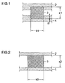
- Fig. 1 is a view showing a cross-sectional structure of the hyper NRD guide in an embodiment;
- Fig. 2 is a view showing a cross-sectional structure the normal NRD guide in the same;
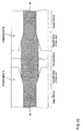
- Figs. 3A to 3C are views showing a structure of the line transforming part of the hyper NRD guide and the normal NRD guide;
- Fig. 4 is a view showing a configuration of a millimeter wave radar module;
- Fig. 5 is an exploded perspective view of the components including an oscillator and an isolator;
- Fig. 6 is a view showing a configuration of a coupler part;
- Fig. 7 is a view showing a cross-sectional structure of a hyper NRD guide in a mixer part;
- Fig. 8 is a plane view showing a configuration of a mixer part;
- Fig. 9 is a cross-sectional view showing a whole structure of the millimeter wave radar module;
- Fig. 10 is a perspective view showing a configuration of a rotational unit;
- Figs. 11A and 11B are views showing a configuration of a primary radiator part;
- Fig. 12 is a view showing the structures of the connection units of the respective NRD guides on the rotational unit side and on the circuit unit side;
- Fig. 13 is an equivalent circuit diagram of the rotational unit in the radar module;
- Fig. 14 is a partial perspective view showing a configuration of the connection unit between the components;
- Fig. 15 is a view showing a configuration of the connection unit between the components;
- Fig. 16A and 16B are diagrams showing the examples of electric field energy distributions in the normal NRD guide and in the hyper NRD guide; and
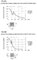
- Fig. 17A to 17C are diagrams showing the examples of characteristics variations according to the switch operations in the normal NRD guide and in the hyper NRD guide.
-
- Referring to Figs. 1 to 13, a configuration of a millimeter radar module that is an embodiment of the present invention will be described in detail.
- As already described above, Fig. 1 is a cross-sectional view of the hyper NRD guide part, Fig. 2 is a cross-sectional view of the normal NRD guide part. In either NRD guide, a
dielectric strip 3 is placed between twoconductor plates dielectric strip 3 is equal to a space between theconductor plates conductor plates conductor plates dielectric strip 3 is made shorter than the height dimension a1 of thedielectric strip 3, thereby the area where there is the dielectric strip is set to be a propagation area where a single mode of the LSM01 propagates. - Figs. 3A to 3C are views showing a structure of the line transformation unit of the normal NRD guide and the hyper NRD guide, and Fig. 3A is a plane view in a state that the upper conductor plate is removed, Fig. 3B is a cross-sectional view of the A-A' part in Fig. 3A, and Fig. 3C is a cross-sectional view of the B-B' part in Fig. 3A. As shown in the figures, in the middle part of the hyper NRD guide and the normal NRD guide, the first transformation unit varies the width b1 of the
dielectric strip 3 in the hyper NRD guide part up to the width b2 in the normal NRD guide, over the distance L1. In association with varying a width of a dielectric strip to a taper form, the widths of the grooves provided in the upper andlower conductor plates dielectric strip 3 has the same width 2b as the dielectric strip in the normal NRD guide part. In the third transformation unit, the widths of the grooves in the upper andlower conductor plates conductor plates - With the structure as described above, by defining the length L2 of the second transformation unit in such a manner that a reflected wave in the first transformation unit and a reflected wave in the third transformation unit are combined in the reversed phase, a different kind of a non radiative dielectric line transformation unit structure with a low reflection in a predetermined frequency band can be obtained.
- Fig. 4 is a view showing a state in which the dielectric lens part in an upper plane (a plane that implements of transmitting and receiving a millimeter wave) of a millimeter wave radar module is removed, and the upper conductor plate is also removed. This millimeter radar module is constituted of the
components rotation unit 103, amotor 104, acasing 105 which accommodates them, and a dielectric lens as not being shown, etc. In thecomponent 101 an oscillator, an isolator and a terminator are provided. In thecomponent 102, a coupler, circulator and a mixer are provided. - Fig. 5 is an exploded perspective view showing a configuration of the above mentioned
component 101. In the figure, 1 indicates the lower conductor plate, and even though they are omitted in the figure, the dielectric strips 31, 32, 33, 46 are placed between the upper conductor plate. 38 indicates a dielectric plate, and various kinds of conductor patterns such as anexcitation probe 39 and the like on a surface thereof. Thisdielectric substrate 38 is placed as sandwiching it between thedielectric strips 31 and 31'. Further, 37 indicates a dielectric resonator, and is placed at where it couples with the predetermined parts of thedielectric strips 31' and 31. 36 indicates a Gunn diode block, and connects one of the electrodes in the Gunn diode to theexcitation probe 39 on thedielectric substrate 38. 35 indicates a ferrite resonator, and a circulator is constituted of this ferrite resonator, three dielectric strips, and a magnet as not being shown. Further, theterminator 34 is provided at the end part of thedielectric strip 33, so as to configure an isolator as a whole. When configuring an oscillator using the dielectric resonator as described above, by letting the NRD guide in the part that couples to thedielectric resonator 37 to be as the normal NRD guide, enabling to make the coupling of them much stronger. Further, thedielectric strip 46 is the one to be connected to one of the dielectric strips that constitute the coupler of thecomponent 102, and theterminator 42 is provided at the end part thereof. - Here, the electric field energy distribution that spread in the transverse direction of the line cross-section from the center of the dielectric strip, for the normal NRD guide and for the hyper NRD guide is shown in Figs. 16A and 16B. As apparent from comparing them, much stronger coupling can be obtained in the normal NRD guide comparing with the hyper NRD guide when placing the dielectric strips as being spaced with the same distance, and thus a variation of the coupling strength for a variation of the distance becomes smooth, thereby the required dimensional accuracy of the relative alignment between the
dielectric resonator 37 and thedielectric strips 31, 31' shown in Fig. 5 becomes lower. - In Fig. 5 the circular part sets, in order to avoid a problem caused by the mode transformation to the LSE01, and also since it is necessary to provide a bend, the dielectric line thereof to be as the hyper NRD guide. Further, in the neighboring parts to this
component 101 the above mentionedcomponent 102 is placed, and thedielectric strip 32 implements a connection of the line as facing to the dielectric strip of thecomponent 102 thereof. Accordingly, this part is to be as a configuration of the normal NRD guide. As shown in the figure, the line transformation units of the normal NRD guide and the hyper NRD guide are provided in these two parts. - Fig. 6 is a view showing a configuration of the coupler part shown in Fig. 4, and is a plane view in a state that the upper conductor plate is removed. As shown in the figure, the coupler is configured by coupling two lines in the parts at where a space g between the
dielectric strips - Fig. 7 is a cross-sectional view showing a configuration of the mixer part shown in Fig. 4. In the figure, 47 indicates a substrate made of a dielectric, and is placed in alignment of sandwiching this
substrate 47 with thedielectric strips lower conductor plates lower conductor plates dielectric strips substrate 47, and the relative permittivities of thedielectric strips substrate 47 are defined in such a manner that the cut-off frequencies of the LSM01 mode in thedielectric strips - Fig. 8 is a plane view in a state that the upper conductor plate in the above mentioned mixer part is removed. 6a, 6b, 7a, 7b, 9a, and 9b indicate, respectively, an open stub with an approximately λ/4, and a space between 6a - 6b, a space between 7a - 7b and a space between 9a - 9b is respectively set as an approximately λ/4. The part in which the open stub of λ/4 is provided with a space of λ/4 apart acts as a band ejection filter (BEF) that ejects a frequency signal with a wavelength λ. Further, by respectively setting the electrical lengths of the spaces L11, L12 from the center of the
filter circuits dielectric strips filter circuits open stub 9a is set in a relation as being an integer multiplicity of an approximately 1/2 wavelength in the frequency of the millimeter wave that propagates on thedielectric strips filter circuits Schottcky barrier diodes conductor pattern 51, in the resonant circuit by theconductor pattern 51 and thefilter circuits dielectric strips diodes dielectric strips diodes conductor pattern 52 is magnetic fieldly coupled with the NRD guide constituted of thedielectric strips diodes conductor pattern 51, the bias voltage supply circuits indicated by Lb, Rb, and Vb are connected, and the end part of thisconductor pattern 51 is high frequencially grounded with a capacitor Cg. With this structure, the frequency components of difference between the RF signal and the Lo signal are combined in phase, and is extracted as an IF signal through a capacitor Ci. Further, the NRD guide by the above mentioneddielectric strips conductor pattern 52 are never coupled in the LSE01 mode. - A configuration of the circular part in the
component 102 shown in Fig. 4 is almost the same as the isolator in thecomponent 101, and is constituted of adielectric strip 40 that is continuous from the coupler part, adielectric strip 45 that is continuous from the mixer part, anotherdielectric strip 44, a ferrite resonator 43 and a magnet as being not shown. - Fig. 9 is a view showing an alignment of the dielectric lens and the rotation unit shown in Fig. 4, and shows a vertical cross-sectional view of a whole millimeter radar module. Fig. 10 is a perspective view showing a configuration of the above mentioned rotation unit.
- In this example, the normal NRD guide is configured by placing the dielectric strips between the respective side planes of the
metal block 14 in a regular pentagon shape and the conductor plates that are in parallel therewith. Further, providing a dielectric resonator between the respective side planes of themetal block 14 and the conductor plates that are in parallel therewith configures a primary radiator. A position of this dielectric resonator is respectively provided in displaced positions in a direction of a rotational axis of the rotation unit, and as the motor rotates the rotation unit it is configured that the position of the primary radiator at the focal position of the dielectric lens switches sequentially in a direction parallel to the rotational axis. - Fig. 11A to 11C are views showing the configurations of one of the dielectric lines and the primary radiator of the rotational unit, Fig. 11A is a top view, and Fig. 11B is a cross-sectional view. Here, 61 indicates a dielectric resonator of the HE111 mode in a cylindrical shape, and is provided at a place where it is apart from the end part of the
dielectric strip 60 with a predetermined distance. A window unit that is opened in a conical shape is provided in one part of theconductor plate 5, so that a radiation and an incidence of the electromagnetic waves are to be made from the upper part in the figure of thisdielectric resonator 61. Providing aslit plate 62 between thedielectric resonator 61 and theconductor plate 5, a radiation pattern is controlled by aslit 63 of thisslit plate 62. - Fig. 12 is a view respectively showing the structures of the connection units of the NRD guides on the above-mentioned rotation unit side and on the circuit part side. Such as this, the NRD guides on the rotation unit side and the NRD guide in the part that selectively connects to these are set to be as the normal NRD guide, and a hyper NRD guide, and a line transformation unit of the hyper NRD guide and the normal NRD guide are provided on the circuit side.
- Fig. 13 is an equivalent circuit diagram of the above-mentioned rotation unit part. As such, a gap between the
rotation unit 103 shown in Fig. 4 and thecomponent 102 acts as a dielectric line switch, and by providing a plurality of dielectric lines and a primary radiator in the rotation unit and then by rotating, switching the primary radiator sequentially, and by varying a relative position for the dielectric lens, a directivity of a beam is varied sequentially. - Here, the characteristics examples of the dielectric line switch according to the hyper NRD guide and of the dielectric line switch according to the normal NRD guide are shown in Figs. 17A to 17C. Fig. 17A in the figure is a view showing a rotational alignment of one of the NRD guides and the other one of the NRD guides, for the dielectric line switch according to the normal NRD guides. Further, Fig. 17B is a view showing the insertion loss characteristics of the dielectric line switch according to the hyper NRD guide and of the dielectric line switch according to the normal NRD guide, and Fig. 17C is a view showing the reflection characteristics of both the dielectric line switches described above. In this example, there are shown the cases that the dimensions of the hyper NRD guide are set to be as a1 = 2.2mm, b1 = 1.8 mm, g=0.5 mm in Fig. 1, and the dimensions of the normal NRD guide are set to be as a2 = 2.2 mm, b2 = 3.0 mm in Fig. 2, and the rotational radius r is set to be 6.1 mm. As such, the insertion loss in the same rotational angle is less and the reflection is also less in the normal NRD guide than the hyper NRD guide, thereby making it possible to implement a switching, while maintaining a connection state over wider rotational angles.
- Fig. 14 is a perspective view showing a structure of the connection unit of the NRD guides in-between two components according to the second embodiment, Fig. 15 is a plane view of the same connection unit. In either case, it is shown in a state that the upper conductor plate is removed. In the first embodiment, an example of two dielectric strips having been faced at the single connection plane, but as shown in Figs. 14 and 15, by providing the connection planes of the dielectric strips at two places, and the distance of the connection planes is set to be an odd number multiplicity of a quarter (1/4) of the in-tube wavelength in the frequencies to be used. With this structure, even though a gap occurred in the connection planes according to a temperature change would vary, it becomes that the reflected waves respectively generated at two planes are combined in the reversed phase, the transmission characteristics will not deteriorate regardless the temperature change. Further, since the transmission characteristics will not deteriorate even though the dimensions of the
dielectric strips - In the present invention, using the respective non radiative dielectric lines to the places suitable for the respective characteristics of the first type of the non radiative dielectric line (the normal NRD guide) and the second type of the non radiative dielectric line (the hyper NRD guide), a non radiative dielectric line part miniaturized as a whole and having an excellent characteristics is obtained.
- In the present invention, the dielectric resonator can be strongly coupled to the non radiative dielectric line, and the manufacturing may be facilitated since the positional accuracy of the non radiative dielectric line and the dielectric resonator is not required so highly.
- In the present invention, a propagation of its LSE01 mode can be prevented without using the LSE01 mode suppresser in the multipointed circulator, and as a result a reduction of the number of parts can be made, thereby no translation loss is generated by the mode transformation of the LSM01 mode and the LSE01 mode.
- In the present invention, the non radiative dielectric lines can be strongly coupled in a short distance, thereby the coupler can be miniaturized.
- In the present invention, since the coupling with its LSE01 mode can be prevented, without using the LSE01 mode suppresser in the mixer, the number of parts can be reduced.
- In the present invention, a degradation of the transmission characteristics caused by a change of the facing alignment of the non radiative dielectric lines is small, thereby the excellent characteristics can be obtained in the insertion loss and the reflection characteristics.
- In the present invention, the problems of the degradation of the characteristics and the unevenness caused by the positional displacement in the connection unit of the non radiative dielectric line parts can be resolved.
- In the present invention, the integrated circuit in which the respective characteristics of the first type of the non radiative dielectric line and the second type of the non radiative dielectric line are utilized is obtained.
- The non radiative dielectric line part of the present invention, providing a dielectric strip between two conductive planes in approximately parallel, using a non radiative dielectric line with an area of the dielectric strip as a propagation area of an electromagnetic wave and with an area other than the area of the dielectric strip as a non-propagation area, includes a first type of non radiative dielectric line in which a space between the conductive planes is made to be approximately equal to a height of the dielectric strip; and a second type of non radiative dielectric line in which the space between the conductive planes in said non-propagation area is made smaller than a space of the conductive planes in the propagation area, in which a cut-off frequency of a LSM01 mode that propagates in the propagation area is lower than a cut-off frequency of a LSE01 mode, and in which only LSM01 mode propagates with a usage frequency.
- With this configuration, by using the respective non radiative dielectric lines to the places suitable for the respective characteristics of the first type of the non radiative dielectric line (the normal NRD guide) and the second type of the non radiative dielectric line (the hyper NRD guide), a non radiative dielectric line part miniaturized as a whole and having an excellent characteristics is obtained.
- In the non radiative dielectric line part of the present invention, the first type of non radiative dielectric line is provided in a part that couples to a dielectric resonator. As a result, the dielectric resonator can be strongly coupled to the non radiative dielectric line, and the manufacturing may be facilitated since the positional accuracy of the non radiative dielectric line and the dielectric resonator is not required so highly.
- In the non radiative dielectric line part of the present invention, the second type of non radiative dielectric line is used for a transmission line of a multipointed circulator. When configuring the multipointed circulator, the end parts of the dielectric line are placed so as to face to the parts of ferrite resonator from different directions (usually, three directions each separating from each other with 120 degrees), and thus even if a propagation mode to be used is the LSM01 mode, it has a tendency to transform to the LSE01 mode as a direction of the dielectric strip changes, at a time when being outputted from one port to other port, but by using the second type of the non radiative dielectric line as a dielectric line, so that a propagation of its LSE01 mode can be prevented without using the LSE01 mode suppresser.
- Further, when connecting the dielectric line in which several dielectric lines are placed in parallel, to the multipointed circulator, the bend part is inevitably generated in the dielectric line part that is input/output for the respective ports of the circulator, by setting this part to be as the second type of non radiative dielectric line continuous from the circulator, no translation loss is generated by the mode transformation of the LSM01 mode and the LSE01 mode in the bend part.
- In the non radiative dielectric line part of the present invention, by drawing the first type of non radiative dielectric lines closer, a coupler that couples them each other is formed. As a result, the non radiative dielectric lines can be strongly coupled in a short distance, thereby the coupler can be miniaturized.
- The non radiative dielectric line part in the present invention forms a mixer by placing two of the second type of non radiative dielectric lines in alignment with an approximately at right angle. For the case of the mixer in which two non radiative dielectric lines are placed in alignment with an approximately at right angle, a conductor pattern that couples to one of the dielectric strips is provided along with a direction of a length of the other one of the dielectric strips, so that it tends to couple with the LSE01 mode in that part, but as a result of using the second type of non radiative dielectric line as a non radiative dielectric line thereof, there is no propagation of the LSE01 mode, thereby it is not necessary to provide the dielectric strip with the mode suppresser of the LSE01 mode.
- The non radiative dielectric line part of the present invention provides the non radiative dielectric line switch that switches a propagation/non propagation of an electromagnetic wave on a line by varying a facing alignment of two of said first type of non radiative dielectric lines is provided. By varying the facing alignment of the non radiative dielectric lines as such, the propagation/non propagation of the electromagnetic wave on the dielectric line can be switched, but since in the first type of the non radiative dielectric line, no electric current flow on a conductor surface in the propagation direction of the electromagnetic wave, so that a degradation of the transmission characteristics caused by a change of the facing alignment of the non radiative dielectric lines is small, thereby the excellent characteristics can be obtained in the insertion loss and the reflection characteristics.
- The non radiative dielectric line part of the present invention provides the first type of non radiative dielectric line in a connection part with neighboring other non radiative dielectric line part. As a result, in the connection part of the non radiative dielectric line parts, as similar to the case in the above mentioned dielectric line switch, the problems of the degradation of the characteristics and the unevenness caused by the positional displacement can be resolved.
- Combining the non radiative dielectric line parts constitutes the non radiative dielectric line integrated circuit of the present invention. With this configuration, the integrated circuit in which the respective characteristics of the first type of the non radiative dielectric line and the second type of the non radiative dielectric line are utilized, is to be obtained.
Claims (8)
- In a non radiative dielectric line part, providing a dielectric strip (3) between two conductive planes (1, 2) in approximately parallel, using a non radiative dielectric line with an area of said dielectric strip (3) as a propagation area of an electromagnetic wave and with an area other than said area of said dielectric strip (3) as a non-propagation area, said non radiative dielectric line part, comprising:a first type of non radiative dielectric line in which a space between said conductive planes (1, 2) is made to be approximately equal to a height (a2) of said dielectric strip (3); anda second type of non radiative dielectric line in which said space between said conductive planes (1, 2) in said non-propagation area is made smaller than a space (a1) of said conductive planes (1, 2) in said propagation area, in which a cut-off frequency of a LSM01 mode that propagates in the propagation area is lower than a cut-off frequency of a LSE01 mode, and in which only LSM01 mode propagates with a usage frequency.
- A non radiative dielectric line part according to claim 1, wherein said first type of non radiative dielectric line is provided in a part that couples to a dielectric resonator (37).
- A non radiative dielectric line part according to claim 1, wherein said second type of non radiative dielectric line is used for a transmission line of a multipointed circulator (40, 43, 44, 45).
- A non radiative dielectric line part according to claim 1, wherein by drawing said first type of non radiative dielectric lines closer, a coupler (40, 41) that couples them each other is formed.
- A non radiative dielectric line part according to claim 1, wherein by placing two of said second type of non radiative dielectric lines in alignment with an approximately at right angle, a mixer (41, 45, 47) is formed.
- A non radiative dielectric line part according to claim 1, wherein a non radiative dielectric line switch that switches a propagation/non propagation of an electromagnetic wave on a line by varying a facing alignment of two (60, 44) of said first type of non radiative dielectric lines is provided.
- A non radiative dielectric line part according to claim 1, wherein said first type of non radiative dielectric line is provided in a connection part (1a, 3a, 1b, 3b) with neighboring other non radiative dielectric line part.
- A non radiative dielectric line integrated circuit that is constituted by combining said non radiative dielectric line parts according to claim 1.
Applications Claiming Priority (2)
| Application Number | Priority Date | Filing Date | Title |
|---|---|---|---|
| JP35737397 | 1997-12-25 | ||
| JP35737397A JP3303757B2 (en) | 1997-12-25 | 1997-12-25 | Non-radiative dielectric line component and integrated circuit thereof |
Publications (2)
| Publication Number | Publication Date |
|---|---|
| EP0926760A1 true EP0926760A1 (en) | 1999-06-30 |
| EP0926760B1 EP0926760B1 (en) | 2003-10-01 |
Family
ID=18453805
Family Applications (1)
| Application Number | Title | Priority Date | Filing Date |
|---|---|---|---|
| EP98124041A Expired - Lifetime EP0926760B1 (en) | 1997-12-25 | 1998-12-17 | Electronic part having non-radiative dielectric waveguide and integrated circuit using the same |
Country Status (7)
| Country | Link |
|---|---|
| US (1) | US6144267A (en) |
| EP (1) | EP0926760B1 (en) |
| JP (1) | JP3303757B2 (en) |
| KR (1) | KR100291767B1 (en) |
| CN (1) | CN1222076C (en) |
| CA (1) | CA2256279C (en) |
| DE (1) | DE69818625T2 (en) |
Cited By (2)
| Publication number | Priority date | Publication date | Assignee | Title |
|---|---|---|---|---|
| WO2002067362A1 (en) * | 2001-02-20 | 2002-08-29 | Nrdtech Co., Ltd. | Ask transceiver |
| EP1324422A3 (en) * | 2001-12-18 | 2003-08-27 | Murata Manufacturing Co., Ltd. | Line coupling structure, mixer, and receiving/transmitting apparatus |
Families Citing this family (14)
| Publication number | Priority date | Publication date | Assignee | Title |
|---|---|---|---|---|
| JP3485054B2 (en) * | 1999-12-28 | 2004-01-13 | 株式会社村田製作所 | Different type non-radiative dielectric line converter structure and device |
| JP3735510B2 (en) * | 2000-04-18 | 2006-01-18 | 株式会社村田製作所 | Transmission line connection structure, high-frequency module, and communication device |
| AU2000261885A1 (en) * | 2000-08-02 | 2002-02-13 | Sensing Tech. Corp. | The multi-space structure amplifier |
| JP2002232212A (en) * | 2001-01-31 | 2002-08-16 | Kyocera Corp | Pulse modulator for non-radiative dielectric line and millimeter wave transceiver using the same |
| KR100572114B1 (en) * | 2002-06-15 | 2006-04-18 | 엔알디테크 주식회사 | Transceiver for Millimeter Wave Band Using NRD Guide |
| JP4095470B2 (en) | 2003-02-26 | 2008-06-04 | 株式会社インテリジェント・コスモス研究機構 | NRD guide bend |
| US20050143017A1 (en) * | 2003-12-31 | 2005-06-30 | Lopp Carl G. | Docking station for enabling landline telephones to send/receive calls via a docked walkie-talkie-type mobile telephone |
| DE102004031355A1 (en) * | 2004-03-31 | 2005-10-27 | Schleifring Und Apparatebau Gmbh | Rotary transformer with dielectric waveguide |
| US7109823B1 (en) | 2005-01-07 | 2006-09-19 | Hrl Lab Llc | Image guide coupler switch |
| KR101136519B1 (en) * | 2010-03-09 | 2012-04-17 | (주)파트론 | Intergrated coupler-circulator and power amplifier compring the same |
| CN104064852A (en) * | 2013-03-19 | 2014-09-24 | 德克萨斯仪器股份有限公司 | Horn antenna for launching electromagnetic signals from a microstrip line into a dielectric waveguide |
| US9270000B2 (en) * | 2013-03-21 | 2016-02-23 | Honeywell International Inc. | Waveguide circulator with improved transition to other transmission line media |
| JP2017011561A (en) * | 2015-06-24 | 2017-01-12 | 京セラ株式会社 | Waveguide structure, and manufacturing method therefor |
| IL292207B2 (en) * | 2019-10-17 | 2026-03-01 | Thruvision Ltd | High frequency heterodyne mixer |
Citations (1)
| Publication number | Priority date | Publication date | Assignee | Title |
|---|---|---|---|---|
| EP0767507A1 (en) * | 1995-10-04 | 1997-04-09 | Murata Manufacturing Co., Ltd. | Dielectric waveguide |
Family Cites Families (4)
| Publication number | Priority date | Publication date | Assignee | Title |
|---|---|---|---|---|
| JP3123293B2 (en) * | 1993-03-05 | 2001-01-09 | 株式会社村田製作所 | Non-radiative dielectric line and method of manufacturing the same |
| JP2846278B2 (en) * | 1996-02-19 | 1999-01-13 | 和歌山県 | Recycling of cured unsaturated polyester resin waste |
| JP3106972B2 (en) * | 1996-08-29 | 2000-11-06 | 株式会社村田製作所 | Diode mount structure, detector and mixer in dielectric line |
| JP3119176B2 (en) * | 1996-10-23 | 2000-12-18 | 株式会社村田製作所 | Antenna shared distributor and transmitter / receiver for dielectric line |
-
1997
- 1997-12-25 JP JP35737397A patent/JP3303757B2/en not_active Expired - Fee Related
-
1998
- 1998-12-17 EP EP98124041A patent/EP0926760B1/en not_active Expired - Lifetime
- 1998-12-17 CA CA002256279A patent/CA2256279C/en not_active Expired - Fee Related
- 1998-12-17 DE DE69818625T patent/DE69818625T2/en not_active Expired - Lifetime
- 1998-12-18 US US09/216,109 patent/US6144267A/en not_active Expired - Lifetime
- 1998-12-24 KR KR1019980058186A patent/KR100291767B1/en not_active Expired - Fee Related
- 1998-12-25 CN CNB981262252A patent/CN1222076C/en not_active Expired - Fee Related
Patent Citations (1)
| Publication number | Priority date | Publication date | Assignee | Title |
|---|---|---|---|---|
| EP0767507A1 (en) * | 1995-10-04 | 1997-04-09 | Murata Manufacturing Co., Ltd. | Dielectric waveguide |
Non-Patent Citations (2)
| Title |
|---|
| TSUKASA YONEYAMA: "MILLIMETER-WAVE INTEGRATED CIRCUITS USING NONRADIATIVE DIELECTRIC WAVEGUIDE", ELECTRONICS & COMMUNICATIONS IN JAPAN, PART II - ELECTRONICS, vol. 74, no. 2, 1 February 1991 (1991-02-01), pages 20 - 28, XP000240840 * |
| XIAO L -L ET AL: "ANALYSIS OF GROOVE NRD WAVEGUIDE BEND USING THE COUPLED-MODE THEORY", INTERNATIONAL JOURNAL OF INFRARED AND MILLIMETER WAVES, vol. 13, no. 7, July 1992 (1992-07-01), pages 971 - 980, XP002022046 * |
Cited By (3)
| Publication number | Priority date | Publication date | Assignee | Title |
|---|---|---|---|---|
| WO2002067362A1 (en) * | 2001-02-20 | 2002-08-29 | Nrdtech Co., Ltd. | Ask transceiver |
| EP1324422A3 (en) * | 2001-12-18 | 2003-08-27 | Murata Manufacturing Co., Ltd. | Line coupling structure, mixer, and receiving/transmitting apparatus |
| US6931246B2 (en) | 2001-12-18 | 2005-08-16 | Murata Manufacturing Co., Ltd. | Line coupling structure, mixer, and receiving/transmitting apparatus comprised of suspended line and dielectric waveguide |
Also Published As
| Publication number | Publication date |
|---|---|
| JP3303757B2 (en) | 2002-07-22 |
| DE69818625D1 (en) | 2003-11-06 |
| CA2256279C (en) | 2002-09-24 |
| KR100291767B1 (en) | 2001-06-01 |
| JPH11191706A (en) | 1999-07-13 |
| US6144267A (en) | 2000-11-07 |
| CN1222076C (en) | 2005-10-05 |
| DE69818625T2 (en) | 2004-08-19 |
| CA2256279A1 (en) | 1999-06-25 |
| KR19990063422A (en) | 1999-07-26 |
| CN1221230A (en) | 1999-06-30 |
| EP0926760B1 (en) | 2003-10-01 |
Similar Documents
| Publication | Publication Date | Title |
|---|---|---|
| EP0926760B1 (en) | Electronic part having non-radiative dielectric waveguide and integrated circuit using the same | |
| EP1473796B1 (en) | Dielectric waveguide | |
| US7142165B2 (en) | Waveguide and slotted antenna array with moveable rows of spaced posts | |
| EP1398848B1 (en) | Laminated aperture antenna and multi-layered wiring board comprising the same | |
| EP0871239B1 (en) | Antenna device and radar module | |
| US5943005A (en) | Multilayer dielectric line circuit | |
| EP1450433B1 (en) | Circuit for suppression of spurious modes on planar transmission lines | |
| KR100326958B1 (en) | Non Radiative Dielectric Waveguide Having A Portion For Line Converstion Between Different Types Of Non Radiative Dielectric Waveguides | |
| JP3013798B2 (en) | Crossing track | |
| EP1324422B1 (en) | Line coupling structure, mixer, and receiving/transmitting apparatus | |
| EP0869573B1 (en) | Dielectric filter and communication apparatus using same | |
| US6342863B2 (en) | Antenna apparatus and antenna and tranceiver using the same | |
| JP3617397B2 (en) | Dielectric line waveguide converter, dielectric line connection structure, primary radiator, oscillator, and transmitter |
Legal Events
| Date | Code | Title | Description |
|---|---|---|---|
| PUAI | Public reference made under article 153(3) epc to a published international application that has entered the european phase |
Free format text: ORIGINAL CODE: 0009012 |
|
| 17P | Request for examination filed |
Effective date: 19981217 |
|
| AK | Designated contracting states |
Kind code of ref document: A1 Designated state(s): DE FI FR GB IT SE |
|
| AX | Request for extension of the european patent |
Free format text: AL;LT;LV;MK;RO;SI |
|
| AKX | Designation fees paid |
Free format text: DE FI FR GB IT SE |
|
| GRAH | Despatch of communication of intention to grant a patent |
Free format text: ORIGINAL CODE: EPIDOS IGRA |
|
| GRAS | Grant fee paid |
Free format text: ORIGINAL CODE: EPIDOSNIGR3 |
|
| GRAA | (expected) grant |
Free format text: ORIGINAL CODE: 0009210 |
|
| AK | Designated contracting states |
Kind code of ref document: B1 Designated state(s): DE FI FR GB IT SE |
|
| PG25 | Lapsed in a contracting state [announced via postgrant information from national office to epo] |
Ref country code: IT Free format text: LAPSE BECAUSE OF FAILURE TO SUBMIT A TRANSLATION OF THE DESCRIPTION OR TO PAY THE FEE WITHIN THE PRESCRIBED TIME-LIMIT;WARNING: LAPSES OF ITALIAN PATENTS WITH EFFECTIVE DATE BEFORE 2007 MAY HAVE OCCURRED AT ANY TIME BEFORE 2007. THE CORRECT EFFECTIVE DATE MAY BE DIFFERENT FROM THE ONE RECORDED. Effective date: 20031001 Ref country code: FI Free format text: LAPSE BECAUSE OF FAILURE TO SUBMIT A TRANSLATION OF THE DESCRIPTION OR TO PAY THE FEE WITHIN THE PRESCRIBED TIME-LIMIT Effective date: 20031001 |
|
| REG | Reference to a national code |
Ref country code: GB Ref legal event code: FG4D |
|
| REF | Corresponds to: |
Ref document number: 69818625 Country of ref document: DE Date of ref document: 20031106 Kind code of ref document: P |
|
| PG25 | Lapsed in a contracting state [announced via postgrant information from national office to epo] |
Ref country code: SE Free format text: LAPSE BECAUSE OF FAILURE TO SUBMIT A TRANSLATION OF THE DESCRIPTION OR TO PAY THE FEE WITHIN THE PRESCRIBED TIME-LIMIT Effective date: 20040101 |
|
| ET | Fr: translation filed | ||
| PLBE | No opposition filed within time limit |
Free format text: ORIGINAL CODE: 0009261 |
|
| STAA | Information on the status of an ep patent application or granted ep patent |
Free format text: STATUS: NO OPPOSITION FILED WITHIN TIME LIMIT |
|
| 26N | No opposition filed |
Effective date: 20040702 |
|
| PGFP | Annual fee paid to national office [announced via postgrant information from national office to epo] |
Ref country code: DE Payment date: 20121213 Year of fee payment: 15 |
|
| PGFP | Annual fee paid to national office [announced via postgrant information from national office to epo] |
Ref country code: GB Payment date: 20121212 Year of fee payment: 15 |
|
| PGFP | Annual fee paid to national office [announced via postgrant information from national office to epo] |
Ref country code: FR Payment date: 20130107 Year of fee payment: 15 |
|
| REG | Reference to a national code |
Ref country code: DE Ref legal event code: R119 Ref document number: 69818625 Country of ref document: DE |
|
| GBPC | Gb: european patent ceased through non-payment of renewal fee |
Effective date: 20131217 |
|
| REG | Reference to a national code |
Ref country code: FR Ref legal event code: ST Effective date: 20140829 |
|
| REG | Reference to a national code |
Ref country code: DE Ref legal event code: R119 Ref document number: 69818625 Country of ref document: DE Effective date: 20140701 |
|
| PG25 | Lapsed in a contracting state [announced via postgrant information from national office to epo] |
Ref country code: DE Free format text: LAPSE BECAUSE OF NON-PAYMENT OF DUE FEES Effective date: 20140701 |
|
| PG25 | Lapsed in a contracting state [announced via postgrant information from national office to epo] |
Ref country code: FR Free format text: LAPSE BECAUSE OF NON-PAYMENT OF DUE FEES Effective date: 20131231 Ref country code: GB Free format text: LAPSE BECAUSE OF NON-PAYMENT OF DUE FEES Effective date: 20131217 |