EP0924881A2 - Feed line connecting circuit and optical transmission system - Google Patents
Feed line connecting circuit and optical transmission system Download PDFInfo
- Publication number
- EP0924881A2 EP0924881A2 EP98123930A EP98123930A EP0924881A2 EP 0924881 A2 EP0924881 A2 EP 0924881A2 EP 98123930 A EP98123930 A EP 98123930A EP 98123930 A EP98123930 A EP 98123930A EP 0924881 A2 EP0924881 A2 EP 0924881A2
- Authority
- EP
- European Patent Office
- Prior art keywords
- feed line
- line connecting
- switch
- connecting terminal
- current
- Prior art date
- Legal status (The legal status is an assumption and is not a legal conclusion. Google has not performed a legal analysis and makes no representation as to the accuracy of the status listed.)
- Granted
Links
Images




Classifications
-
- H—ELECTRICITY
- H04—ELECTRIC COMMUNICATION TECHNIQUE
- H04B—TRANSMISSION
- H04B10/00—Transmission systems employing electromagnetic waves other than radio-waves, e.g. infrared, visible or ultraviolet light, or employing corpuscular radiation, e.g. quantum communication
- H04B10/80—Optical aspects relating to the use of optical transmission for specific applications, not provided for in groups H04B10/03 - H04B10/70, e.g. optical power feeding or optical transmission through water
- H04B10/806—Arrangements for feeding power
- H04B10/808—Electrical power feeding of an optical transmission system
Definitions
- This invention relates to a feed line connecting circuit, more particularly to a circuit for connecting power feeding lines, especially suitable for use in a branching unit of an optical fiber transmission system.
- the invention also relates to an optical transmission system of a double branching type using the feed line connecting circuit.
- Branching units of optical fiber transmission systems use a feed line, which has three connection terminals A, B and C, and can connect the power feeding lines between trunks or between a trunk and a branch as desired by connecting two terminals. Since power can be supplied to other power feeding lines connected to the last terminal independently from power feeding lines connected to the former two of terminals by connecting the last terminal to ground, the circuit typically has a circuit arrangement that can selectively connect terminals B and C to ground.
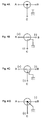
- Figs. 4A through 4D show aspects of connection of a conventional feed line connecting circuit.
- Fig. 4A shows an unpowered condition
- Fig. 4B shows the condition where the terminal A and the terminal B are connected
- Fig. 4C shows the condition where the terminal A and the terminal C are connected
- Fig. 4D shows the condition where the terminals B and C are connected to ground.
- sings (+) and (-) show relative potentials. By establishing any of these potential conditions, a desired configuration of connection is selected.
- terminals A, B and C are usually connected to each other and float from ground to permit an insulation electric test. Due to a current flowing from the terminal A to the terminal B, which applies a plus potential to the terminal A and a minus potential to the terminal B, the terminal C is disconnected from the terminals A and B and connected to ground as shown in Fig. 4B, and this state of connection is maintained. When a plus potential is applied to the terminal A while a minus potential is applied to the terminal C, the terminal B is disconnected from the terminals A and C and connected to ground as shown in Fig. 4C, and this state of connection is maintained. When a minus potential is applied to both terminals B and C, all terminals A, B and C result in being connected to ground as shown in Fig. 4D.
- the conventional feed line connecting circuit is configured to always connect one or more of out-of-use feed line connecting terminals to ground.
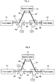
- FIG. 5 is a block diagram schematically showing the construction of a double branching type of power feeding system.
- Reference numerals 10 and 12 denote trunk stations, 14 is a branch station, and 16a and 16b are (feed line connecting circuits of) branching units.
- a power feeding line 20 connects the trunk station 10 to the feed line connecting terminal A of the branching unit 16a, and a power feeding line 22 connects the feed line connecting terminal C of the branching unit 16a to the branch station 14.
- the power feeding line 24 connects the branch station 14 to the feed line connecting terminal C of the branching unit 16b, and the feed line 26 connects the feed line connecting terminal B of the branching unit 16b to the trunk station 12.
- a power feeding line 28 connects the feed line connecting terminal B of the branching unit 16a to the feed line connecting terminal A of the branching unit 16b.
- the branching units 16a, 16b are installed in relatively short distances around 20 km, the trunk cables used there are usually configured for non-repeated transmission, and need no power source.
- the feed line connecting circuit of the branching unit 16a is in the condition of Fig. 4B where the feed line connecting terminals A and C are connected, rendering the trunk station 10 in a plus potential and the branch station 14 in a minus potential, and power is supplied to the power feeding lines 20 and 22 between the trunk station 10 and the branch station 14.
- the feed line connecting circuit of the branching unit 16b is in the state of Fig.
- the feed line connecting circuit of the branching unit 16a changes to the configuration shown in Fig. 4B where the feed line connecting terminals A and B are connected to each other, and the power feeding system exhibits the configuration shown in Fig. 6. That is, the power feeding line 20 connects to the power feeding line 28, and falls to the earth at the feed line connecting terminal A of the branching unit 16b.
- the feed line connecting circuit of the branching unit 16a a large current flows when connection of the feed line connecting terminal B changes from the earth to the feed line connecting terminal A, and may damage the relay circuit in which the current flows.
- Another object of the invention is to provide a feed line connecting circuit not inviting the above-explained problems even in a double branching system.
- a further object of the invention is to provide a feed line connecting circuit capable of holding an out-of-use feed line connecting terminal floating from ground or terminated at a resistor in a specific state of connection.
- a feed line connecting circuit connected between one of first and second feed line connecting terminals and a central node are a first current detector for detecting a current above a predetermined value and a first switch for connecting one of the first and second feed line connecting terminals to the central node in the unpowered condition.
- a selective switch for connecting to a first selective contact when the first current detector does not detect any current above the predetermined value, and for connecting to a second selective contact when the first current detector detects a current above the predetermined value.
- a common contact of the selective switch connects to a third feed line connecting terminal.
- a second current detector for switching the first switch so as to disconnect said one of the first and second feed line connecting terminals from the central node when detecting a current above the predetermined value.
- the first, second and third feed line connecting terminals are connected in the unpowered condition.
- the first switch is switched by the second current detector, and the second (or first) feed line connecting terminal is disconnected from the central node.
- the second (or first) feed line connecting terminal can be floated from ground by floating the contact of the first switch, and it can be terminated in a resistor by connecting the contact of the first switch to ground via the resistor.
- the third feed line connecting terminal is disconnected from the central node by the selective switching means.
- the second selective contact of the selective switching means is connected to ground directly or via a resistor, power can be supplied to a power feeding line connected to the third feed line connecting terminal independently from power feeding lines connected to the first and second feed line connecting terminals.
- the first feed line connecting terminal can be disconnected from the central node when a current flows between the second feed line connecting terminal and the third feed line connecting terminal.
- the second feed line connecting terminal can be disconnected from the central node when a current flows between the first feed line connecting terminal and the third feed line connecting terminal.
- a third current detector is connected between the second selective contact of the selective switch and ground; a normally closed second switch, which is open when the third current detector detects a current above a predetermined value, is connected between the first selective contact of the selective switch and the central node; and a normally open third switch, which is closed when the third current detector detects a current above the predetermined value, is connected between the common contact and the second selective contact of the selective switch.
- the first feed line connecting terminal and the second feed line connecting terminal can be connected reliably even if any short-circuiting trouble occurs at the third feed line connecting terminal.
- the bypass circuit may comprise a Zener diode, for example.
- opposite ends of a power feeding line between the first and second branching units are held floating from the earth or connected to the earth via a resistor. Then, it is prevented that a large current flows in the power feeding line between the branching units even when breakage of any power feeding line, for example, causes unintentional changes in connected configuration of power feeding lines in the first or second branching unit which may cause the power feeding line between the first and second branch unit to be incorporated into the power feeding system. Additionally, by maintaining the opposite ends of the power feeding line between the branching units, a loop current does not flow in the power feeding line between the first and second branching units in the normal status, and therefore, corrosion of the electrode by loop current can be prevented.
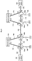
- Fig. 1 is a schematic block diagram showing a general arrangement of a double branching optical transmission system employing an embodiment of the invention.
- Numerals 30, 32 denote trunk stations, 34 is a branch station, and 36a and 36b are (feed line connecting circuits of) branching units which connects the branch station 34 to a trunk cable between the trunk stations 30 and 32.
- a power feeding line 40 connects the trunk station 30 to a feed line connecting terminal A1 of the branching unit 36a, and a power feeding line 42 connects a feed line connecting terminal C1 of the branching unit 36a to the branch station 34.
- a power feeding line 44 connects the branch station 34 to a feed ling connecting terminal C2 of the branching unit 36b, and a power feeding line 46 connects a feed line connecting terminal B2 of the branching unit 36b to the trunk station 32.
- a power feeding line 48 connects a feed line connecting terminal B1 of the branching unit 36a to a feed line connecting terminal A2 of the branching unit 36b.
- the feed line connecting terminal A1 is in direct connection to a central node O1, and the feed line connecting terminal B1 connects to the central node O1 via a relay circuit 50a and a normally closed switch 52a.
- a Zener diode 54a is connected in parallel with the relay circuit 50a to bypass a current flowing in the direction from the feed line connecting terminal B1 toward the central node O1.
- the central node O1 is connected also to the feed line connecting terminal C1 via a resistor 56a for preventing damage due to short circuit, a relay circuit 58a, a normally closed switch 60a, and a selective contact a and a common contact c of a switch 62a.
- a normally open switch 64a is connected in parallel with the resistor 56a.
- a Zener diode 66a is connected in parallel with the relay circuit 58a to bypass a current in the direction from the terminal C1 toward the central node O1.
- the switch 62a has two selective contacts a and b and a common contact c, and the common contact c normally connects to the selective contact a .
- the selective contact a of the switch 62a connects to the switch 60a whereas the common contact c connects to the feed line connecting terminal C1.
- the selective contact b of the switch 62a is connected to ground through the relay circuit 68a.
- a Zener diode 70a is connected in parallel with the relay circuit 68a to bypass a current flowing from the selective contact b of the switch 62a toward the earth. Further connected between the common contact c (i.e., the feed line connecting terminal C1) and the selective contact b of the switch 62a is a normally open switch 72a.
- the switch 62a is controlled by the relay circuit 50a to change its connection. More specifically, the relay circuit 50a connects the switch 62 to the selective contact a during no substantial flow of current, and changes connection of the switch 62a to the selective contact b when a current above a predetermined value flows.
- the relay circuit 58a is configured to open a switch 52a and close a switch 64a when a current above a predetermined value flows.
- the relay circuit 68a is configured to open a normally closed switch 60a and close a normally open switch 72 when a current over a predetermined value flows.
- a resistor is connected between the feed line connecting terminal A1 and the central node O1 to generate a source voltage from a voltage drop of the resistor and to supply power to the circuit required.
- FIG. 2A shows an unpowered condition
- Fig. 2B shows A-B connecting condition where the feed line connecting terminals A1 and B1 are connected to each other
- Fig. 2C shows A-C connecting conditions where the feed line connecting terminal A1 and C1 are connected to each other.
- the embodiment shown here cannot realize the status corresponding to Fig. 4D where all of the feed line connecting terminals A1, B1 and C1 are connected to ground.
- a plus potential is applied to the feed line connecting terminal A1 whereas a minus potential is applied to the feed line connecting terminal B1. Then, a current flows from the feed line connecting terminal A1 toward the feed line connecting terminal B1. Since this direction is the reverse direction for the Zener diode 54a, an amply large current flows in the relay circuit 50a, and the relay circuit 50a changes connection of the switch 62a to the selective contact b. However, the current flowing in the relay circuit 50a is limited by the breakdown voltage of the Zener diode 54a. As a result, the feed line connecting terminal C1 is disconnected from the central node O1, and connected to the earth through the selective contact b of the switch 62a and the relay circuit 68a. This is just the status shown in Fig. 2B.
- the feed line connecting terminal C1 exhibits a minus potential relative to the earth, then a current flows in the relay circuit 68a, and the relay circuit 68a opens the switch 60a and closes the switch 72a.
- the feed line connecting terminal C1 is connected to ground via the switch 72a and the relay circuit 68a and self-maintained in the connection to ground, being unrelated to the connectiong status of the swithc 62a.
- the feed line connecting terminal C1 exhibits a plus potential relative to the earth, then a current from the feed line connecting terminal C1 toward the earth flows in the Zener diode 70a, and a current required does not flow in the relay circuit 68a. As a result, the switch 72a is held open, and the switch 60a is held closed. Even then, as long as the a current flows in the relay circuit 50a, the switch 62a connects to the selective contact b, and the feed line connecting terminal C1 is disconnected from the central node O1 and connects to ground.
- a source current can be flown in the power feeding line connected to the feed line connecting terminal C1 independently from power feeding lines connected to feed line connecting terminals A1 and B1.
- connection of the switch 62a changes to the selective contact a, and results in the feed line connecting terminal C1 being connected to the central node O1.
- connection configuration shown in Fig. 2B can be established by applying a potential of the above-mentioned polarity between the feed line connecting terminals A1 and B1.
- a plus potential is applied to the feed line connecting terminal A1 and a minus potential is applied to the feed line connecting terminal C1 from the unpowered condition.
- the switch 60a closes, and the switch 62a connects at the selective contact a. Therefore, a current flows from the feed line connecting terminal A1 to the feed line connecting terminal C1 through the resistor 56a, relay circuit 58a, switch 60a, selective contact a and common contact c of the switch 62a. Because a current over a predetermined value flows in the relay circuit 58a, the switch 64a closes and the switch 52a opens. Because the switch 52a opens, the feed line connecting terminal B1 is disconnected from the central node O1. Because the switch 64a closes, the resistor 56a is bypassed, and useless voltage drop does not occur.
- the feed line connecting circuit is basically similar to that of the branching unit 36a, and its components 50b through 72b correspond to the components 50a through 72a of the branching unit 36a, and they are different in the following points. That is, in the branching unit 36a, the relay circuit 50a, switch 52a and Zener diode 54a are connected between the feed line connecting terminal B1 and the central node O1. In the branching unit 36b, similar relay circuit 50b, switch 52b and Zener diode 54b are connected between the feed line connecting terminal A2 and the central node O2, and the feed line connecting terminal B2 directly connects to the central node O2.
- the Zener diode is connected in orientation to bypass the relay circuit 50b in the direction from the central node O2 to the feed line connecting terminal A2.
- the Zener diode 66b is connected in orientation to make a current from the central node O2 toward the feed line connecting terminal C2 to bypass the relay circuit 58b.
- functions of the Zener diodes 54b, 66b and 70b are like those of the Zener diodes 54a, 66b and 70a, and they prevent that any excessive current flows into the relay circuits 50b, 58b and 68b.
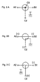
- FIG. 3A shows an unpowered condition
- Fig. 3B shows A-B connecting condition where the feed line connecting terminals A2 and B2 are connected to each other
- Fig. 3C shows A-C connecting condition where the feed line connecting terminal A2 and C2 are connected to each other.
- the embodiment shown here cannot realize the status corresponding to Fig. 4D where all of the feed line connecting terminals A2, B2 and C2 are connected to ground.
- a plus potential is applied to the feed line connecting terminal A2 whereas a minus potential is applied to the feed line connecting terminal B2. Then, a current flows from the feed line connecting terminal A2 toward the feed line connecting terminal B2. Since this direction is the opposite direction for the Zener diode 54b, an amply large current flows in the relay circuit 50b, and the relay circuit 50b changes connection of the switch 62b to the selective contact b. However, the current flowing in the relay circuit 50b is limited by the breakdown voltage of the Zener diode 54b. As a result, the feed line connecting terminal C2 is disconnected from the central node O2, and connected to the earth through the selective contact b of the switch 62a and the relay circuit 68b. This is just the status shown in Fig. 3B.
- the feed line connecting terminal C2 exhibits a minus potential relative to the earth, then a current flows in the relay circuit 68b, and the relay circuit 68b opens the switch 60b and closes the switch 72b.
- the feed line connecting terminal C2 is connected to ground via the switch 72b and the relay circuit 68b and self-maintained in the connection to ground, being unrelated to the connecting status of the switch 62b.
- the feed line connecting terminal C2 exhibits a plus potential relative to the earth, then a current from the feed line connecting terminal C2 toward the earth flows in the Zener diode 70b, and a current required does not flow in the relay circuit 68b. As a result, the switch 72b is held open, and also the switch 60b is held closed. Even then, as long as the a current flows in the relay circuit 50b, the switch 62b connects to the selective contact b, and the feed line connecting terminal C2 is disconnected from the central node O2 and connects to ground.
- a source current can be flown in the power feeding line connected to the feed line connecting terminal C2 independently from power feeding lines connected to feed line connecting terminals A2 and B2.
- connection of the switch 62b changes to the selective contact a , and results in the feed line connecting terminal C2 being connected to the central node O2.
- connection configuration shown in Fig. 3B can be established by applying a potential of the above-mentioned polarity between the feed line connecting terminals A2 and B2.
- a plus potential is applied to the feed line connecting terminal C2 and a minus potential is applied to the feed line connecting terminal B2 from the unpowered condition.
- the switch 60b closes, and the switch 62b connects at the selective contact a. Therefore, a current flows from the feed line connecting terminal C2 to the feed line connecting terminal B2 through the common contact c and selective contact a of the switch 62b, switch 60b, relay circuit 58b and resistor 56b. Because a current over a predetermined value flows in the relay circuit 58b, the switch 64b closes and the switch 52b opens. Because the switch 52b opens, the feed line connecting terminal A2 is disconnected from the central node O2. Because the switch 64b closes, the resistor 56b is bypassed, and useless voltage drop does not occur.
- the feed line connecting terminal B1 of the branching unit 36a and the feed line connecting terminal A2 of the branching unit 36b can be disconnected from the central nodes O1 and O2 under floating from ground.
- the branching unit 36a has been explained as connecting the selective contact b of the switch 62a to the earth via the parallel circuits of the relay circuit 68a and the Zener diode 70a; however, the selective contact b may be directly connected to the earth. In this case, the switch 60a always maintains connection, and it becomes substantially useless. The same applies also to the switch 62b, relay circuit 68b, Zener diode 70b and switch 60b of the branching unit 36b.
- the switch 52a has been explained as being opened by the relay circuit 58a; however, equivalent effects can be obtained also by replacing it with a switch which connects the feed line connecting terminal B1 to the central node O1 in the normal state (when no current flows in the relay circuit 58a) and connects the feed line connecting terminal B1 to ground via a large resistor when a current over a predetermined value flows in the relay circuit 58a. That is, when the feed line connecting terminals A1 and C1 are connected to each other, the problems involved in the conventional circuit can be removed even by connecting the feed line connecting terminal B1 to ground via a large resistor. The same applies also to the branching unit 36b.
- Fig. 7 is a schematic block diagram showing a general construction of a power feeding system according to the second embodiment.
- Numerals 110 and 112 denote trunk stations
- 114 is a branch station
- 116a and 116b are (feed line connecting circuits of) branching units which connect the branch station 114 to a trunk cable between the trunk stations 110 and 112.
- a power feeding line 120 connects the trunk station 110 to a feed line connecting terminal A1 of the branching unit 116a
- a power feeding line 122 connects a feed line connecting terminal C1 of the branch unit 116a to the branch station 114.
- a power feeding line 124 connects the branch station 114 to a feed line connecting terminal C2, and a power feeding line 126 connects a feed line connecting terminal B2 of the branch unit 116b to the trunk station 112.
- a power feeding line 128 connects a feed line connecting terminal B1 of the branching unit 116a to a feed line connecting terminal A2 of the branching unit 116b.
- the feed line connecting terminal A1 directly connects to a central node O1 which connects to a selective contact a of a selective switch 130a.
- a selective contact b of the selective switch 130a connects to ground through a resistor 132a, and a common contact c of the selective switch 130a connects to the feed line connecting terminal B1 via parallel circuits of a relay circuit 134a and a Zener diode 136a.
- the selective switch 130a normally contacts at the selective contact a.
- the Zener diode 136a is so connected that the direction from the feed line connecting terminal B1 toward the central node O1 be forward.
- the central node O1 also connects to a selective contact a of a selective switch 142a via parallel circuits of a relay circuit 138a and a Zener diode 140a.
- a selective contact b of the selective switch 142a connects to ground through a resistor 144a, and a common contact c of the selective switch 142a connects to the feed line connecting terminal C1.
- the selective switch 142a normally connects at the selective contact a .
- the Zener diode 140a is so connected that the direction from the feed line connecting terminal C1 toward the central node O1 be forward.
- the relay circuit 134a changes connection of the selective switch 142a to the selective contact b when a current above a predetermined value flows.
- the relay circuit 138a changes connection of the selective switch 132a to the selective contact b when a current above the predetermined value flows.
- the potential difference in the relay circuits 134a and 138a is limited by breakdown voltages of the Zener diodes 136a and 140a connected in parallel. That is, the Zener diodes 136a and 140a prevent that excessive current flows in the relay circuits 134a and 138a.
- the feed line connecting circuit of the branching unit 116a is largely different from that of the branching unit 36a in the embodiment shown in Fig. 1 in that the feed line connecting terminals B1 and C1 disconnected from the central node O1 are connected to ground not directly but via the resistors 132a and 144a and in that it does not include a circuit for automatically maintaining connection of the feed line connecting terminal C1 to ground when such connection is established.
- a plus potential is applied to the feed line connecting terminal A1 and a minus potential is applied to the feed line connecting terminal C1 from the unpowered condition.
- a current flows in the relay circuit 128a.
- a current over a predetermined value flows in the relay circuit 138a, it changes connection of the selecting switch 132a to the selective contact b.
- the feed line connecting terminal B1 is disconnected from the central node O1 and connected to ground through the resistor 132a.
- the feed line connecting terminals B1 and C1 cannot be connected to each other.
- the feed line connecting circuit of the branching unit 116b is similar to the feed line connecting circuit of the branching unit 116a.
- a feed line connecting terminal B2 directly connects to a central node O2 which connects to a selective contact a of the selective switch 130b.
- a selective contact b of the selective switch 130b is connected to ground through a resistor 132b, and a common contact c of the selective switch 130b is connected to a feed line connecting terminal A2 via parallel circuits of a relay circuit 134b and a Zener diode 136b.
- the selective switch 130b normally connects at the selective contact a .
- the Zener diode 136b is so connected that the direction from the central node O2 toward the feed line connecting terminal A2 be forward.
- the central node O2 also connects to a selective contact a of a selective switch 142b through parallel circuits of a relay circuit 138b and a Zener diode 140b.
- a selective contact b of the selective switch 142b connects to ground through a resistor 144b, and a common contact c of the selective switch 142b connects to a feed line connecting terminal C2.
- the selective switch 142b normally connects at the selective contact a .
- the Zener diode 140b is so connected that the direction from the central node O2 toward the feed line connecting terminal C2 be forward.
- the relay circuit 134b changes connection of the selective switch 142b to the selective contact b when a current above a predetermined value flows.
- the relay circuit 138b changes connection of the selective switch 132b to the selective contact b when a current over a predetermined value flows.
- the Zener diodes 136a and 140a prevent that an excessive current flows in the relay circuits 134b and 138b.
- a plus potential is applied to the feed lien connecting terminal A2 and a minus potential is applied to the feed line connecting terminal B2 under the unpowered condition. Then, a current flows from the feed line connecting terminal A2 toward the feed line connecting terminal B2. Since an amply large current flows in the relay circuit 134b, it changes connection of the switch 142b to the selective contact b. As a result, the feed line connecting terminal C2 is disconnected from the central node O2 and connected to ground through the resistor 144b. In this status, power can be supplied to the power feeding line 124 independently from the power feeding lines 126 and 128 by applying a plus or minus potential to the terminal of the branching unit 114 connected to the power feeding line 124.
- a plus potential is applied to the feed line connecting terminal C2 and a minus potential is applied to the feed line connecting terminal B2 from the unpowered condition.
- the selective switch 142b connects at the selective contact a , a current flows from the feed line connecting terminal C2 to the feed line connecting terminal B2 through the common contact c and selective contact a of the switch 142b and the relay circuit 138b.
- the selective switch 130b changes connection to the selective contact b.
- the feed line connecting terminal A2 is disconnected from the central node O2 and connected to ground through the relay circuit 134b (or Zener diode 136b) and the resistor 132b.
- the embodiment shown here disconnects the feed line connecting terminal B1 of the branching unit 116a and the feed line connecting terminal A2 of the branching unit 116b from the central nodes O1 and O2 and connects them to ground through the resistors 132a and 132b, respectively. It results in connecting opposite ends of the power feeding line 128 to ground through the resistors 132a and 132b.
- the connection of the selective switch 130a returns to the selective contact a , and the feed line connecting terminal B1 connects to the central node O1, i.e., the feed line connecting terminal A1.
- Fig. 7 shows the power feeding configuration under normal power feeding.
- Numerals 150 and 152 denote trunk stations, 154 and 156 are branch stations, 158a and 158b are (feed line connecting circuits of) branching units for the branch station 154, and 160a and 160b are (feed line connecting circuits of) branching units for the branch station 156.
- the feed line connecting circuit shown in the branching unit 116a of Fig. 7 is employed, whereas the feed line connecting circuit shown in the branching unit 116b in Fig. 7 is employed in the branching units 158b and 160b.
- a power feeding line 162 is connected between the trunk station 150 and a feed line connecting terminal A1 of the branching unit 158a (corresponding to the feed line connecting terminal A1 of the branching unit 116a), a power feeding line 164 is connected between a feed line connecting terminal C1 of the branching unit 158a (corresponding to the feed line connecting terminal C1 of the branching unit 116a) and the branch station 154, a power feeding line 166 is connected between the branch station 154 and a feed line connecting terminal C2 of the branching unit 158b (corresponding to the feed line connecting terminal C2 of the branching unit 116b), and a power feeding line 168 is connected between a feed line connecting terminal B1 of the branching unit 158a (corresponding to the feed line connecting terminal B1 of the branching unit 116a) and a feed line connecting terminal A2 of the branching unit 158b (corresponding to the feed line connecting terminal A2 of the branching unit 116b).
- a power feeding line 170 is connected between a feed line connecting terminal B2 of the branching unit 158b (corresponding to the feed line connecting terminal B2 of the branching unit 116b) and a feed line connecting terminal A3 of the branching unit 160a (corresponding to the feed line connecting terminal A1 of the branching unit 116a).
- a power feeding line 172 is connected between a feed line connecting terminal C3 of the branching unit 160a (corresponding to the feed line connecting terminal C1 of the branching unit 116a) and the branch station 156.
- a power feeding line 174 is connected between the branch station 156 and a feed line connecting terminal C4 of the branching unit 160b (corresponding to the feed line connecting terminal C2 of the branching unit 116b).
- a power feeding line 176 is connected between a feed line connecting terminal B3 of the branching unit 160a (corresponding to the feed line connecting terminal B1 of the branching unit 116a) and a feed line connecting terminal A4 of the branching unit 160b (corresponding to the feed line connecting terminal A2 of the branching unit 116b).
- a power feeding line 178 is connected between a feed line connecting terminal B4 of the branching unit 160a (corresponding to the feed line connecting terminal B2 of the branching unit 116b) and the trunk station 152.
- the power feeding lines 168 and 176 between adjacent branching units 158a, 158b and between adjacent branching units 160a 160b connected to the same branch stations 154, 156 are connected to ground at their opposite ends through high resistors 180, 182 184, 186 as explained with reference to Fig. 7.
- the branch station 150 When the trunk station 150 applied a plus potential (or current) to the power feeding line 162 and the branch station 154 applies a minus potential (or current) to the power feeding line 164 while opening the connection points of the branch station 156 and trunk station 152 to the power feeding lines 172, 174 and 178, the feed ling connecting terminals A1 and C1 of the branching unit 158a are connected to each other, and the feed line connecting terminal B1 is connected to sea ground via the resistor 180, as explained above.
- a plus current is applied from a constant current source built in the branch station 154 to the power feeding line 166
- a minus current is applied from a constant current source built in the branch station 156 to the power feeding line 172.
- quantities of the currents applied to the power feeding lines 166 and 172 are increased gradually or stepwise from zero, and the rising time of the constant current source and the speed of increasing the current is equalized between the branch stations 154 and 156.
- an equal current flows in the power feeding lines 166, 170 and 172, and due to the behavior of the relay circuits explained with reference to Fig.
- a plus current is applied to the power feeding line 174 from a constant current source built in the branch station 156
- a minus current is applied to the power feeding line 178 from a constant current source built in the trunk station 152.
- quantities of the currents applied to the power feeding lines 174 and 178 are increased gradually or stepwise from zero, and the rising time of the constant current source and the speed of increasing the current are equalized between the branch station 156 and the trunk station 152.
- an equal current flows in the power feeding lines 174 and 178.
- the feed line connecting terminal C4 and B4 are connected to each other and the feed line connecting terminal A4 is connected to sea ground via the resistor 186.
- the power feeding lines 162 through 178 are connected, and power feeding lines 168 and 176 between adjacent branching units 158a and 158b and between adjacent branching units 160a and 160b are connected to ground at their opposite ends via high resistors 180, 182, 184 and 186 corresponding to the resistors 132a and 132b.
- the power feeding system can be changed as shown in Fig. 9.
- power feeding to the power feeding lines 162 and 166 from the branch station 154 is stopped, and connection points of the branch station 154 connected to the power feeding lines 162 and 166 are opened.
- the branching unit 158a the feed line connecting terminals A1, B1 and C1 are connected to each other; and in the branching unit 158b, the feed line connecting terminals A2, B2 and C2 are connected to each other.
- a plus current is applied to the power feeding line 162 from the constant current source built in the trunk station 150
- a minus current is applied to the power feeding line 172 from the constant current source built in the branch station 156.
- quantities of the currents applied to the power feeding lines 162 and 172 are increased gradually or stepwise from zero, and the rising time of the constant current source and the speed of increasing the current are equalized between the trunk stations 150 and the branch station 156.
- feed line connecting terminals currently disconnected can be held floating from grounds or connected to grounds via high resistors. As a result, it is prevented that useless current or excessive current flows in power feeding lines connected to the feed line connecting terminals. Moreover, when a power feeding line between two branching units in a double branching system is held floating from grounds or connected to grounds via high resistors at opposite ends thereof, it is prevented that a large current flows even when the configuration of connection of feed line connecting terminals automatically changes in any of the branching unit due to breakage of any of the power feeding lines.
Landscapes
- Physics & Mathematics (AREA)
- Electromagnetism (AREA)
- Engineering & Computer Science (AREA)
- Computer Networks & Wireless Communication (AREA)
- Signal Processing (AREA)
- Cable Transmission Systems, Equalization Of Radio And Reduction Of Echo (AREA)
- Optical Communication System (AREA)
Abstract
Description
Claims (13)
- A feed line connecting circuit for selectively connecting first, second and third feed line connecting terminals under a predetermined current feeding condition, comprising:a first current detector connected between one of said first and second feed line connecting terminals and a central node for detecting a current over a predetermined value;a first switch connected between said one of the first and second feed line connecting terminals and said central node for connecting said one of the first and second feed line connecting terminals to said central node under an unpowered condition;a selective switch controlled by said first current detector to connect at a first selective contact when said first current detector does not detect a current over a predetermined value or to connect at a second selective contact when said first current detector detects a current over the predetermined value, said selective switch having a common contact connected to said third feed line connecting terminal; anda second current detector connected between said first selective contact of said selective switch and said central node to change said first switch so as to disconnect said one of the first and second feed line connecting terminals from said central node when detecting a current above a predetermined value.
- The feed line connecting circuit according to claim 1 wherein said first current detector and said first switch are connected between said second feed line connecting terminal and said central node.
- The feed line connecting circuit according to claim 1 wherein said first current detector and said first switch are connected between said first feed line connecting terminal and said central node.
- The feed line connecting circuit according to one of claims 1 to 3 wherein said second selective contact of said selective switch is connected to ground via a predetermined resistance value.
- The feed line connecting circuit according to one of claims 1 to 3 wherein said second selective contact of said selective switch is connected to ground.
- The feed line connecting circuit according to one of claims 1 to 5 further comprising a third current detector connected between said second selective contact of said selective switch and ground; a second switch connected between said first selective contact of said selective switch and said central node to be normally closed and be opened when said third current detector detects a current above a predetermined value; and a third switch connected between said common contact and said second selective contact of said selective switch to be normally opened and be closed when said third current detector detects a current above the predetermined value.
- The feed line connecting circuit according to one of claims 1 to 6 further comprising a resistor connected between said first selective contact of said selective switch and said central node; and a fourth switch connected in parallel with said resistor to be closed by said second current detector when a current above a predetermined value flows into said second current detector.
- The feed line connecting circuit according to one of claims 1 to 7 further comprising a bypass circuit connected in parallel with each of said first, second and third current detectors for bypassing a current in a predetermined direction.
- The feed line connecting circuit according to claim 8 wherein said bypass circuit comprises a Zener diode.
- The feed line connecting circuit according to one of claims 1 to 9 wherein said first switch is configured to connect said one of the first and second feed line connecting terminals to ground via a resistor when said one of the first and second feed line connecting terminals is disconnected from said central node.
- An optical transmission system including a branch station connected to a trunk optical line through first and second branching units, characterized in holding opposite ends of a power feeding line between said first and second branching units floating from ground connection.
- An optical transmission system including a branch station connected to a trunk optical line through first and second branching units, characterized in connecting opposite ends of a power feeding line between said first and second branching units to ground through a resistor.
- The optical transmission system according to claim 11 or 12 wherein said first branching unit includes the feed line connecting circuit recited in Claim 2 whereas said second branching unit includes the feed line connecting circuit recited in claim 3.
Priority Applications (1)
| Application Number | Priority Date | Filing Date | Title |
|---|---|---|---|
| EP03025382A EP1404035A3 (en) | 1997-12-19 | 1998-12-16 | Feed line connecting circuit and optical transmission system |
Applications Claiming Priority (2)
| Application Number | Priority Date | Filing Date | Title |
|---|---|---|---|
| JP35035097 | 1997-12-19 | ||
| JP9350350A JPH11186959A (en) | 1997-12-19 | 1997-12-19 | Feeding line connection circuit and optical transmission system |
Related Child Applications (1)
| Application Number | Title | Priority Date | Filing Date |
|---|---|---|---|
| EP03025382A Division EP1404035A3 (en) | 1997-12-19 | 1998-12-16 | Feed line connecting circuit and optical transmission system |
Publications (3)
| Publication Number | Publication Date |
|---|---|
| EP0924881A2 true EP0924881A2 (en) | 1999-06-23 |
| EP0924881A3 EP0924881A3 (en) | 2000-05-31 |
| EP0924881B1 EP0924881B1 (en) | 2004-03-24 |
Family
ID=18409899
Family Applications (2)
| Application Number | Title | Priority Date | Filing Date |
|---|---|---|---|
| EP03025382A Withdrawn EP1404035A3 (en) | 1997-12-19 | 1998-12-16 | Feed line connecting circuit and optical transmission system |
| EP98123930A Expired - Lifetime EP0924881B1 (en) | 1997-12-19 | 1998-12-16 | Feed line connecting circuit and optical transmission system |
Family Applications Before (1)
| Application Number | Title | Priority Date | Filing Date |
|---|---|---|---|
| EP03025382A Withdrawn EP1404035A3 (en) | 1997-12-19 | 1998-12-16 | Feed line connecting circuit and optical transmission system |
Country Status (3)
| Country | Link |
|---|---|
| US (1) | US6157098A (en) |
| EP (2) | EP1404035A3 (en) |
| JP (1) | JPH11186959A (en) |
Cited By (16)
| Publication number | Priority date | Publication date | Assignee | Title |
|---|---|---|---|---|
| EP1282240A1 (en) * | 2001-07-18 | 2003-02-05 | Mitsubishi Denki Kabushiki Kaisha | Feed line switching circuit and branching unit |
| WO2010132292A1 (en) * | 2009-05-15 | 2010-11-18 | Corning Cable Systems Llc | POWER DISTRIBUTION DEVICES, SYSTEMS, AND METHODS FOR RADIO-OVER-FIBER (RoF) DISTRIBUTED COMMUNICATION |
| US9160449B2 (en) | 2010-10-13 | 2015-10-13 | Ccs Technology, Inc. | Local power management for remote antenna units in distributed antenna systems |
| US9166690B2 (en) | 2012-09-25 | 2015-10-20 | Corning Optical Communications LLC | Power distribution module(s) for distributed antenna systems, and related power units, components, systems, and methods |
| US9252874B2 (en) | 2010-10-13 | 2016-02-02 | Ccs Technology, Inc | Power management for remote antenna units in distributed antenna systems |
| US9497706B2 (en) | 2013-02-20 | 2016-11-15 | Corning Optical Communications Wireless Ltd | Power management in distributed antenna systems (DASs), and related components, systems, and methods |
| US9509133B2 (en) | 2014-06-27 | 2016-11-29 | Corning Optical Communications Wireless Ltd | Protection of distributed antenna systems |
| US9653861B2 (en) | 2014-09-17 | 2017-05-16 | Corning Optical Communications Wireless Ltd | Interconnection of hardware components |
| US9685782B2 (en) | 2010-11-24 | 2017-06-20 | Corning Optical Communications LLC | Power distribution module(s) capable of hot connection and/or disconnection for distributed antenna systems, and related power units, components, and methods |
| US9729251B2 (en) | 2012-07-31 | 2017-08-08 | Corning Optical Communications LLC | Cooling system control in distributed antenna systems |
| US9785175B2 (en) | 2015-03-27 | 2017-10-10 | Corning Optical Communications Wireless, Ltd. | Combining power from electrically isolated power paths for powering remote units in a distributed antenna system(s) (DASs) |
| US10257056B2 (en) | 2012-11-28 | 2019-04-09 | Corning Optical Communications LLC | Power management for distributed communication systems, and related components, systems, and methods |
| EP3540892A1 (en) * | 2018-03-16 | 2019-09-18 | Alcatel Submarine Networks | Transmission system having a trunk and a branch |
| US10455497B2 (en) | 2013-11-26 | 2019-10-22 | Corning Optical Communications LLC | Selective activation of communications services on power-up of a remote unit(s) in a wireless communication system (WCS) based on power consumption |
| US10992484B2 (en) | 2013-08-28 | 2021-04-27 | Corning Optical Communications LLC | Power management for distributed communication systems, and related components, systems, and methods |
| US11296504B2 (en) | 2010-11-24 | 2022-04-05 | Corning Optical Communications LLC | Power distribution module(s) capable of hot connection and/or disconnection for wireless communication systems, and related power units, components, and methods |
Families Citing this family (10)
| Publication number | Priority date | Publication date | Assignee | Title |
|---|---|---|---|---|
| US7233744B1 (en) * | 1999-10-07 | 2007-06-19 | Tyco Telecommunications (Us) Inc. | Power feed arrangement using aggregate segments |
| US6414405B1 (en) * | 1999-12-13 | 2002-07-02 | Tyco Telecommunications (Us) Inc. | Method and apparatus for operating cabled-fiber undersea network, and fault-tolerant branching unit for use therein |
| US6496626B2 (en) * | 2000-12-21 | 2002-12-17 | Nortel Networks Limited | Telecommunications system power supply |
| US6765775B2 (en) * | 2000-12-27 | 2004-07-20 | Pirelli Cavi E Sistemi S.P.A. | Submarine cable branching unit with current limiter |
| US9143845B2 (en) * | 2011-12-22 | 2015-09-22 | Nec Corporation | Branching units and power line monitoring methods |
| CN105474552B (en) * | 2013-08-23 | 2018-03-16 | 日本电气株式会社 | Feeder line switching circuit, branch device, submarine cable system and feeder line switching method |
| PT2874333T (en) * | 2013-11-14 | 2016-11-16 | Padtec S A | Branching unit for an optical telecommunication link |
| US10110321B2 (en) * | 2017-03-16 | 2018-10-23 | Tyco Electronics Subsea Communications Llc | Techniques for providing adaptive power distribution using a multi-node network of power feed branching units (PFBUs) and an undersea optical communication system using same |
| CN112385148B (en) * | 2018-07-24 | 2022-06-03 | 日本电气株式会社 | Communication system, monitoring device and monitoring method for communication system |
| US10777336B1 (en) * | 2019-04-12 | 2020-09-15 | Subcom, Llc | Branching unit for power distribution |
Family Cites Families (4)
| Publication number | Priority date | Publication date | Assignee | Title |
|---|---|---|---|---|
| GB2252686A (en) * | 1991-02-08 | 1992-08-12 | Stc Plc | Power feed branching unit for submarine telecommunications systems |
| US5491368A (en) * | 1992-04-15 | 1996-02-13 | Fujitsu Limited | Power feed path switching circuit |
| JP3694053B2 (en) * | 1994-03-05 | 2005-09-14 | エステイーシー・サブマリン・システムズ・リミテッド | Branch device for submarine communication system |
| JP3387614B2 (en) * | 1994-03-17 | 2003-03-17 | 富士通株式会社 | Underwater branching equipment power supply switching circuit |
-
1997
- 1997-12-19 JP JP9350350A patent/JPH11186959A/en not_active Withdrawn
-
1998
- 1998-12-16 EP EP03025382A patent/EP1404035A3/en not_active Withdrawn
- 1998-12-16 EP EP98123930A patent/EP0924881B1/en not_active Expired - Lifetime
- 1998-12-21 US US09/217,172 patent/US6157098A/en not_active Expired - Fee Related
Cited By (37)
| Publication number | Priority date | Publication date | Assignee | Title |
|---|---|---|---|---|
| EP1282240A1 (en) * | 2001-07-18 | 2003-02-05 | Mitsubishi Denki Kabushiki Kaisha | Feed line switching circuit and branching unit |
| AU764275B2 (en) * | 2001-07-18 | 2003-08-14 | Kddi Submarine Cable Systems Inc. | Feed line switching circuit and branching unit |
| WO2010132292A1 (en) * | 2009-05-15 | 2010-11-18 | Corning Cable Systems Llc | POWER DISTRIBUTION DEVICES, SYSTEMS, AND METHODS FOR RADIO-OVER-FIBER (RoF) DISTRIBUTED COMMUNICATION |
| US8155525B2 (en) | 2009-05-15 | 2012-04-10 | Corning Cable Systems Llc | Power distribution devices, systems, and methods for radio-over-fiber (RoF) distributed communication |
| US9699723B2 (en) | 2010-10-13 | 2017-07-04 | Ccs Technology, Inc. | Local power management for remote antenna units in distributed antenna systems |
| US10425891B2 (en) | 2010-10-13 | 2019-09-24 | Corning Optical Communications LLC | Power management for remote antenna units in distributed antenna systems |
| US9252874B2 (en) | 2010-10-13 | 2016-02-02 | Ccs Technology, Inc | Power management for remote antenna units in distributed antenna systems |
| US9419712B2 (en) | 2010-10-13 | 2016-08-16 | Ccs Technology, Inc. | Power management for remote antenna units in distributed antenna systems |
| US10750442B2 (en) | 2010-10-13 | 2020-08-18 | Corning Optical Communications LLC | Local power management for remote antenna units in distributed antenna systems |
| US11671914B2 (en) | 2010-10-13 | 2023-06-06 | Corning Optical Communications LLC | Power management for remote antenna units in distributed antenna systems |
| US9160449B2 (en) | 2010-10-13 | 2015-10-13 | Ccs Technology, Inc. | Local power management for remote antenna units in distributed antenna systems |
| US11178609B2 (en) | 2010-10-13 | 2021-11-16 | Corning Optical Communications LLC | Power management for remote antenna units in distributed antenna systems |
| US10849064B2 (en) | 2010-10-13 | 2020-11-24 | Corning Optical Communications LLC | Power management for remote antenna units in distributed antenna systems |
| US10420025B2 (en) | 2010-10-13 | 2019-09-17 | Corning Optical Communications LLC | Local power management for remote antenna units in distributed antenna systems |
| US11224014B2 (en) | 2010-10-13 | 2022-01-11 | Corning Optical Communications LLC | Power management for remote antenna units in distributed antenna systems |
| US10045288B2 (en) | 2010-10-13 | 2018-08-07 | Corning Optical Communications LLC | Power management for remote antenna units in distributed antenna systems |
| US10104610B2 (en) | 2010-10-13 | 2018-10-16 | Corning Optical Communications LLC | Local power management for remote antenna units in distributed antenna systems |
| US11212745B2 (en) | 2010-10-13 | 2021-12-28 | Corning Optical Communications LLC | Power management for remote antenna units in distributed antenna systems |
| US9685782B2 (en) | 2010-11-24 | 2017-06-20 | Corning Optical Communications LLC | Power distribution module(s) capable of hot connection and/or disconnection for distributed antenna systems, and related power units, components, and methods |
| US11114852B2 (en) | 2010-11-24 | 2021-09-07 | Corning Optical Communications LLC | Power distribution module(s) capable of hot connection and/or disconnection for wireless communication systems, and related power units, components, and methods |
| US10454270B2 (en) | 2010-11-24 | 2019-10-22 | Corning Optical Communicatons LLC | Power distribution module(s) capable of hot connection and/or disconnection for wireless communication systems, and related power units, components, and methods |
| US11296504B2 (en) | 2010-11-24 | 2022-04-05 | Corning Optical Communications LLC | Power distribution module(s) capable of hot connection and/or disconnection for wireless communication systems, and related power units, components, and methods |
| US11715949B2 (en) | 2010-11-24 | 2023-08-01 | Corning Optical Communications LLC | Power distribution module(s) capable of hot connection and/or disconnection for wireless communication systems, and related power units, components, and methods |
| US9729251B2 (en) | 2012-07-31 | 2017-08-08 | Corning Optical Communications LLC | Cooling system control in distributed antenna systems |
| US9166690B2 (en) | 2012-09-25 | 2015-10-20 | Corning Optical Communications LLC | Power distribution module(s) for distributed antenna systems, and related power units, components, systems, and methods |
| US10999166B2 (en) | 2012-11-28 | 2021-05-04 | Corning Optical Communications LLC | Power management for distributed communication systems, and related components, systems, and methods |
| US10530670B2 (en) | 2012-11-28 | 2020-01-07 | Corning Optical Communications LLC | Power management for distributed communication systems, and related components, systems, and methods |
| US10257056B2 (en) | 2012-11-28 | 2019-04-09 | Corning Optical Communications LLC | Power management for distributed communication systems, and related components, systems, and methods |
| US11665069B2 (en) | 2012-11-28 | 2023-05-30 | Corning Optical Communications LLC | Power management for distributed communication systems, and related components, systems, and methods |
| US9497706B2 (en) | 2013-02-20 | 2016-11-15 | Corning Optical Communications Wireless Ltd | Power management in distributed antenna systems (DASs), and related components, systems, and methods |
| US10992484B2 (en) | 2013-08-28 | 2021-04-27 | Corning Optical Communications LLC | Power management for distributed communication systems, and related components, systems, and methods |
| US11516030B2 (en) | 2013-08-28 | 2022-11-29 | Corning Optical Communications LLC | Power management for distributed communication systems, and related components, systems, and methods |
| US10455497B2 (en) | 2013-11-26 | 2019-10-22 | Corning Optical Communications LLC | Selective activation of communications services on power-up of a remote unit(s) in a wireless communication system (WCS) based on power consumption |
| US9509133B2 (en) | 2014-06-27 | 2016-11-29 | Corning Optical Communications Wireless Ltd | Protection of distributed antenna systems |
| US9653861B2 (en) | 2014-09-17 | 2017-05-16 | Corning Optical Communications Wireless Ltd | Interconnection of hardware components |
| US9785175B2 (en) | 2015-03-27 | 2017-10-10 | Corning Optical Communications Wireless, Ltd. | Combining power from electrically isolated power paths for powering remote units in a distributed antenna system(s) (DASs) |
| EP3540892A1 (en) * | 2018-03-16 | 2019-09-18 | Alcatel Submarine Networks | Transmission system having a trunk and a branch |
Also Published As
| Publication number | Publication date |
|---|---|
| EP1404035A3 (en) | 2005-07-06 |
| EP0924881A3 (en) | 2000-05-31 |
| EP1404035A2 (en) | 2004-03-31 |
| JPH11186959A (en) | 1999-07-09 |
| EP0924881B1 (en) | 2004-03-24 |
| US6157098A (en) | 2000-12-05 |
Similar Documents
| Publication | Publication Date | Title |
|---|---|---|
| US6157098A (en) | Feed line connection circuit and optical transmission system | |
| US5214312A (en) | Power feed line switching circuit for submarine branching device and method of feeding power to submarine cable communication system | |
| SE507046C2 (en) | Electronic annular bus system divided into several sections | |
| US4798969A (en) | Power feed system in transmission line between terminals of three-terminal station | |
| US6166836A (en) | Power switching of optical fibre cable branching units | |
| JPH0897692A (en) | Diverging device for sea bottom communication system | |
| JPH04336820A (en) | Submarine telecommunication system | |
| JP3387614B2 (en) | Underwater branching equipment power supply switching circuit | |
| EP0780994B1 (en) | Feeding path switching circuit | |
| JP2010249631A (en) | Battery voltage measuring device | |
| EP1841086B1 (en) | Power feed system for a transmission network, in particular a submarine transmission network | |
| JP2786524B2 (en) | Feeding line switching circuit for undersea branching device and method for feeding power in undersea cable communication system | |
| US5347417A (en) | Power supply protection system applied to optical subscriber network | |
| US7067940B2 (en) | Submarine branching unit having asymmetrical architecture | |
| GB2280341A (en) | Power feed line switching circuit for submarine branching device and method of feeding power to submarine cable communication system | |
| EP1294113B1 (en) | Branching unit for an optical transmission system | |
| JP3341246B2 (en) | Power supply line switching circuit | |
| JPH05129991A (en) | Feeder changeover circuit | |
| JPH04304716A (en) | Submarine cable system power feeding system | |
| EP1322046B1 (en) | Submarine branching unit having asymmetrical architecture | |
| JPS6131657B2 (en) | ||
| JP2001230707A (en) | Feeder connection device | |
| JPH0232588B2 (en) | ||
| JPH01289323A (en) | Feeding switching system for submarine relay transmission line | |
| JPH06217354A (en) | Main wire release system |
Legal Events
| Date | Code | Title | Description |
|---|---|---|---|
| PUAI | Public reference made under article 153(3) epc to a published international application that has entered the european phase |
Free format text: ORIGINAL CODE: 0009012 |
|
| AK | Designated contracting states |
Kind code of ref document: A2 Designated state(s): FR GB |
|
| AX | Request for extension of the european patent |
Free format text: AL;LT;LV;MK;RO;SI |
|
| PUAL | Search report despatched |
Free format text: ORIGINAL CODE: 0009013 |
|
| AK | Designated contracting states |
Kind code of ref document: A3 Designated state(s): AT BE CH CY DE DK ES FI FR GB GR IE IT LI LU MC NL PT SE |
|
| AX | Request for extension of the european patent |
Free format text: AL;LT;LV;MK;RO;SI |
|
| RIC1 | Information provided on ipc code assigned before grant |
Free format text: 7H 04B 10/12 A, 7H 04B 3/44 B |
|
| 17P | Request for examination filed |
Effective date: 20000425 |
|
| AKX | Designation fees paid |
Free format text: FR GB |
|
| 17Q | First examination report despatched |
Effective date: 20030204 |
|
| REG | Reference to a national code |
Ref country code: DE Ref legal event code: 8566 |
|
| GRAP | Despatch of communication of intention to grant a patent |
Free format text: ORIGINAL CODE: EPIDOSNIGR1 |
|
| GRAS | Grant fee paid |
Free format text: ORIGINAL CODE: EPIDOSNIGR3 |
|
| GRAA | (expected) grant |
Free format text: ORIGINAL CODE: 0009210 |
|
| RIN1 | Information on inventor provided before grant (corrected) |
Inventor name: NAZUKA, ETSUO C/O KDD SUBMARINE CABLE SYSTEMS INC. Inventor name: TATEKURA, KOH-ICHI, C/O KDD SUBMARINE CABLE Inventor name: KAWAZAWA, TOSHIO Inventor name: GOTO, KOJI Inventor name: ASAKAWA, KENICHI Inventor name: KOJIMA, JUNICH |
|
| AK | Designated contracting states |
Kind code of ref document: B1 Designated state(s): FR GB |
|
| REG | Reference to a national code |
Ref country code: GB Ref legal event code: FG4D |
|
| PGFP | Annual fee paid to national office [announced via postgrant information from national office to epo] |
Ref country code: GB Payment date: 20041206 Year of fee payment: 7 |
|
| ET | Fr: translation filed | ||
| PGFP | Annual fee paid to national office [announced via postgrant information from national office to epo] |
Ref country code: FR Payment date: 20041221 Year of fee payment: 7 |
|
| PLBE | No opposition filed within time limit |
Free format text: ORIGINAL CODE: 0009261 |
|
| STAA | Information on the status of an ep patent application or granted ep patent |
Free format text: STATUS: NO OPPOSITION FILED WITHIN TIME LIMIT |
|
| 26N | No opposition filed |
Effective date: 20041228 |
|
| PG25 | Lapsed in a contracting state [announced via postgrant information from national office to epo] |
Ref country code: GB Free format text: LAPSE BECAUSE OF NON-PAYMENT OF DUE FEES Effective date: 20051216 |
|
| GBPC | Gb: european patent ceased through non-payment of renewal fee |
Effective date: 20051216 |
|
| PG25 | Lapsed in a contracting state [announced via postgrant information from national office to epo] |
Ref country code: FR Free format text: LAPSE BECAUSE OF NON-PAYMENT OF DUE FEES Effective date: 20060831 |
|
| REG | Reference to a national code |
Ref country code: FR Ref legal event code: ST Effective date: 20060831 |