EP0924713A1 - Connector holder - Google Patents
Connector holder Download PDFInfo
- Publication number
- EP0924713A1 EP0924713A1 EP98310149A EP98310149A EP0924713A1 EP 0924713 A1 EP0924713 A1 EP 0924713A1 EP 98310149 A EP98310149 A EP 98310149A EP 98310149 A EP98310149 A EP 98310149A EP 0924713 A1 EP0924713 A1 EP 0924713A1
- Authority
- EP
- European Patent Office
- Prior art keywords
- connector
- holder
- cable
- positioning
- protection material
- Prior art date
- Legal status (The legal status is an assumption and is not a legal conclusion. Google has not performed a legal analysis and makes no representation as to the accuracy of the status listed.)
- Withdrawn
Links
- 239000000463 material Substances 0.000 claims abstract description 41
- 230000001105 regulatory effect Effects 0.000 claims abstract description 29
- 238000003825 pressing Methods 0.000 claims description 9
- 238000000034 method Methods 0.000 claims description 4
- 239000011347 resin Substances 0.000 description 5
- 229920005989 resin Polymers 0.000 description 5
- 230000000712 assembly Effects 0.000 description 4
- 238000000429 assembly Methods 0.000 description 4
- 238000004519 manufacturing process Methods 0.000 description 4
- 238000003780 insertion Methods 0.000 description 3
- 230000037431 insertion Effects 0.000 description 3
- 239000007779 soft material Substances 0.000 description 3
- 230000002146 bilateral effect Effects 0.000 description 1
- 238000004891 communication Methods 0.000 description 1
- 238000010276 construction Methods 0.000 description 1
- 230000003247 decreasing effect Effects 0.000 description 1
- 238000006073 displacement reaction Methods 0.000 description 1
- 238000000605 extraction Methods 0.000 description 1
- 230000001788 irregular Effects 0.000 description 1
- 239000002184 metal Substances 0.000 description 1
- 230000035515 penetration Effects 0.000 description 1
- 230000000717 retained effect Effects 0.000 description 1
- 125000000391 vinyl group Chemical group [H]C([*])=C([H])[H] 0.000 description 1
- 229920002554 vinyl polymer Polymers 0.000 description 1
Images





Classifications
-
- H—ELECTRICITY
- H01—ELECTRIC ELEMENTS
- H01B—CABLES; CONDUCTORS; INSULATORS; SELECTION OF MATERIALS FOR THEIR CONDUCTIVE, INSULATING OR DIELECTRIC PROPERTIES
- H01B13/00—Apparatus or processes specially adapted for manufacturing conductors or cables
- H01B13/012—Apparatus or processes specially adapted for manufacturing conductors or cables for manufacturing wire harnesses
- H01B13/01209—Details
-
- Y—GENERAL TAGGING OF NEW TECHNOLOGICAL DEVELOPMENTS; GENERAL TAGGING OF CROSS-SECTIONAL TECHNOLOGIES SPANNING OVER SEVERAL SECTIONS OF THE IPC; TECHNICAL SUBJECTS COVERED BY FORMER USPC CROSS-REFERENCE ART COLLECTIONS [XRACs] AND DIGESTS
- Y10—TECHNICAL SUBJECTS COVERED BY FORMER USPC
- Y10S—TECHNICAL SUBJECTS COVERED BY FORMER USPC CROSS-REFERENCE ART COLLECTIONS [XRACs] AND DIGESTS
- Y10S269/00—Work holders
- Y10S269/903—Work holder for electrical circuit assemblages or wiring systems
Definitions
- the present invention relates to a connector holder, and more particularly, to a connector holder for use in the process of assembling a wiring harness and a subassembly (hereinafter generally referred to as a "wire assembly").
- a wire assembly consists of a circuit having a cable constructed of a plurality of wires, several connectors connected to the wires, the wires surrounded by protection material such as flexible tubes, corrugated tubes, and the like.
- the wire assembly is arranged in a tree configuration containing a trunk line and branch wires branching from the trunk line, wherein a terminal connector is connected to a respective branch wire.
- several connector holders are vertically mounted on a work bench, called a wiring board, then the wires are arranged on the wiring board in a predetermined configuration by connecting a wire with a respective connector mounted on the connector holder. Protection material such as flexible tubing is then mounted onto a predetermined area about the wires of the cable and fastened to the cable by means of taping or the like.
- protection materials are usually visually and manually installed, i.e., the installer positions the material solely by intuition, which causes variations that result in positioning error, thereby making it difficult to meet the recently-required positioning accuracy of wire assemblies.
- the present invention solves the above problems, and the subject of the present invention is to provide a connector holder capable of increasing the positioning accuracy of protection material when manufacturing wire assemblies.
- the present invention provides a connector holder for use in conjunction with a wiring board when assembling wire assemblies.
- the wiring board has at least one cable to be connected with a connector, each cable comprising one or more wires.
- the wiring board additionally has protection material such as flexible tubing for arrangement about the wires of the cable, and a support member such as a pillar is provided for mounting the invention to the wiring board.
- the invention includes a holder portion which houses a connector in an insertable and removable manner in such a condition that the wires can be connected thereto, and a positioning member which is integrally provided with the holder portion and assists in the positioning of protection material about cable wires connected to the connector.
- a connector to be connected with cable wires is positioned by insertion into the holder portion. Additionally, the present invention enables protection material to be accurately positioned about the cable at a predetermined distance from the positioned connector.
- the positioning member may be adjustably fastened to the holder portion and is changeable according to the direction of the cable wire connected with the connector.
- the vertical mounting of the connector holder of the present invention to a wiring board more easily facilitates the manufacture of the connector holder and wire assembly, because the positioning member allows change in accordance with the direction onto which a wire connected with the connector is arranged. It is thus easier to use the connector holder of the present invention for a wide variety of wire assembly tasks.
- the positioning member may be a pin capable of positioning protection material arranged around the periphery of a cable in such a condition that at least two wires of the cable connected with a connector is arranged on both sides of the positioning member. Since the wires are arranged on both sides of the pin, protection materials may be more easily and accurately positioned on the cable, even when the protection material is constructed of soft material. Additionally, interference between the cable wires connected with the connector and the pin is more readily avoided, thereby reducing the possibility of wiring failures.
- the holder portion may hold a connector with a connector-regulating member which positions the side of a connector where the cable is to be inserted therein, so that the cable connected with the connector is disengageable.
- a resilient member such as a regulating tool, which resiliently presses the connector against the connector-regulating member may be provided, and may further include a base portion which is integrally provided with the connector-regulating member and holds the lower surface of the connector to be mounted.
- the side of a connector where the cable is to be inserted may be positioned by a connector regulating member.
- the connector may be pressed against the connector regulating member by a resilient member so that the lower surface of connector is further retained by a base portion.
- the connector may also be detached from the holder so that the connector is wholly disengaged therefrom.
- the resilient member may have an aperture for providing the adjustment of the distance between the pressing area of the resilient member and the connector-regulating member, thereby allowing the invention to accommodate connectors of varying size.
- the above-mentioned positioning member and a holder may be configured in such a manner that the interval between the front-end face and the back face (referred to as "protection material regulating dimension") of the positioning member is relatively adjustable, thereby providing the invention with increased flexibility and versatility when mounting protection material.
- Figure 1 shows a perspective view of a connector bolder 10 according to a first embodiment of the present invention
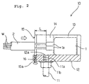
- Figure 2 shows a partial sectional schematic view of the connector holder 10 in Figure 1.
- the connector holder 10 in this embodiment has a support member such as a pillar 11 provided in a wiring board (not illustrated herein), and a holder portion 12 formed on the upper side of the pillar 11.
- the pillar 11 is ideally a metallic round-bar member, although it may be formed of other materials in alternative embodiments.
- the pillar 11 is fastened to the wiring board by known means (for instance, by screw thread or the like).
- the holder portion 12 has a box configuration and is preferably formed of a resin. At the bottom of the holder portion 12 a screw hole 12a is provided for engaging with a screw thread 11a provided on the upper end area of the pillar 11. The holder portion 12 is secured to the pillar 11 by fastening the bottom face of the holder portion 12 by a nut 11b engaged with the screw thread 11a.
- the holder portion 12 is provided with a housing recessed area 13 which is sectioned for housing a connector 1.
- the housing recessed area 13 is set so that a predetermined specific connector 1 having an irregular form (as seen in Figure 1) and dimension may be inserted and extracted in a downward or upward direction only.
- the connector 1 is inserted into the housing recessed area 13 so that the side of the connector that is to be connected to the cable can be oriented towards a slit 14 which allows insertion/extraction of cable W integrally with the connector 1.
- the slit 14 is in open communication with the housing recessed area 13.
- the connector 1 shown is of the water-proof type, and a boss 1a which houses a rubber cap (not illustrated herein) adhered to a cable W is provided.
- the boss 1a is housed in the housing recessed area 13 and is embedded in the above-mentioned slit 14 and then held by a holder portion 12. It will be readily appreciated by those skilled in the art that a standard, non-waterproof type of connector 1 may also be used in with the present invention 10.
- a positioning member such as a pin 15 is provided inside the slit 14, the pin 15 serving to assist in the positioning of protection material on a cable W which is in turn connected with a connector 1. As shown in Fig 1., the edge face of the protection material 2 is fastened at the opening area of the slit 14, thereby positioning the protection material when taping the material to the cable W.
- a pin screw hole 16 is provided at the bottom of the opening area of slit 14 in the example as shown here, and is engaged with a larger diameter screw 15a provided at the end of pin 15. Therefore, with the example as shown in Figures 1 and 2, the height may be made adjustable according to the dimension of the connector.
- the pin 15 allows arrangement of the cable W on both sides thereof.
- the protection material 2 may be accurately positioned even if the protection material 2 is constructed of soft material. Interference between the cable W connected with the connector 1 and the pin 15 is eliminated, therefore reducing the possibility of failure in wiring work.
- Figures 3-6 show a connector holder 210 according to a second preferred embodiment of the present invention.
- the holder portion 20 holds a connector 1 in such a condition that the side of the connector 1 that is to be connected to the cable is positioned upright, and is devoid of a slit which is formed on the holder portion 12 of the first preferred embodiment.
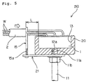
- a pin 15 is vertically mounted by first providing a mounting plate 21 between a holder portion 20 and a pillar 11 in a cantilever-type manner, and engaging a screw thread 15a of a pin 15 with a screw hole 21a provided near the distal end of the mounting plate 21.
- the proximal end of the mounting plate 21 has a section for a flat oval hole 22 which permits penetration of a screw thread 11a that is located on the upper end of the pillar 11.
- the pillar 11 is fastened to the holder portion 20 in such a manner that the distance between the holder portion 20 and the pin 15 may be adjusted by screwing the nut 11b over the screw thread 11a which is then inserted into the flat oval hole 22 when fastening the holder portion 20 onto the pillar by engaging the holder portion 20 with the screw thread 11a.
- Figure 6 shows the variable mounting positions of the mounting plate 21 of the second embodiment. Because the position of the pin 15 may be changed in relation to the longitudinal axis of the pillar 11, the position of the pin 15 allows changes in accordance with a direction D of a cable W. In Figure 6, four directions D are shown along each of an outer side of the four-sided connector 1. Therefore, the connector holder 210 may be mounted to a wiring board without any restrictions as to the mounting position and the type of wire assembly to be assembled, which makes the present invention extremely versatile.
- the pin 15 allows the protection material 2 to be positioned from the connector 1 by a precise protection material-regulated dimension L. Dimensional accuracy is therefore increased when mounting protection material 2 to a cable W during manufacture of a wire assembly.
- the pin 15 may be omitted in the example shown in Figure 1, which permits positioning of a protection material 2 by an open-ended portion 12b of slit 14.
- FIG. 7 a third embodiment of the connector holder 310 is shown, Figure 7 representing a perspective view and Figure 8 representing a side schematic view.
- the third embodiment includes a holder portion 12 having a resin mold that is integrally provided with a base portion 30, a connector regulating member in the form of a "U"-shaped wall portion 31 which is vertically mounted on the base portion, and an "L"-shaped regulating portion 38.
- the base portion 30 has a substantially cuboidal form, and a pin 15 is provided on the upper area of the base portion, at the base of the "U"-shaped wall portion.
- the "U"-shaped wall portion 31 regulates a side 1b of a connector 1 where the cable is to be inserted 1b.
- the "U"-shaped wall portion 31 has an insertion recessed portion 31a generally having a U-shape which forms the bilateral symmetry of the "U"- shaped wall portion 31, the wall portion 31 having the pin 15 as its symmetrical axis.
- Front end-face 31b of the wall portion 31 is flush with edge of the pin 15, shown in Figure 8.
- back face 31c of the "U"-shaped wall portion 31 makes contact with the side of the connector 1 where the cable is to be inserted. As illustrated in Figure 8, the interval between the front end-face 31b and a back face 31c determines a protection material regulating dimension L.
- the regulating tool 33 is an integrally-formed generally "L"-shaped resin mold and includes a generally planar mounting portion 33a and a pressing portion 33b.
- a base portion 30 is secured to the mounting portion 33a by a nut 11b of a pillar 11, and has a front end-face 31b, a back face 31c, and a generally "U"- shaped wall portion 31 which extends upward from a longitudinal back end-portion of the mounting portion 33a.
- the regulating tool 33 is ideally constructed of resin, it may be constructed of other materials such as metal in alternative embodiments.
- the pressing portion 33b has a generally " ⁇ "-shaped bent portion 33d at the middle area thereof, and the bent portion 33d protrudes towards the "U"-shaped wall portion 31.
- this bent portion 33d may be dimensionally configured so as to press the bent portion 33d against the connector 1, and the connector may be below the bent portion 33d, as discussed in the fourth embodiment below and shown in Figure 10.
- the regulating tool 33 secures the connector 1 in cooperation with the "U"- shaped wall portion 31 by resiliently urging the connector 1 towards the back-face 31c of the "U"- shaped wall portion 31 by the spring-function of the pressing portion 33b.
- the base portion 30, the "U"-shaped wall portion 31, and the regulating tool 33 enable complete detachment of the connector 1 from the holder portion 12. Therefore, this embodiment 310 facilitates easy detaching of the connector 1, reducing the possibility of wiring failures between the connector 1 and the cable W.
- an oval flat hole 33c is present along the longitudinal direction on the mounting portion 33a of the regulating tool 33.
- the pillar 11 penetrates the oval flat hole 33c and is threadedly inserted into the base portion 30, which is integrally formed with the "U"-shaped wall portion 31 and the pin 15.
- the oval flat hole 33c provides for the sliding adjustment of the pressing portion 33b of the regulating tool 33, which can either increase or decrease the distance between the pressing portion 33b of the regulating tool 33, thereby enabling the present invention to a accommodate connectors 1 of varying size.
- Figures 9 and 10 represent a fourth preferred embodiment of the present invention, Figure 9 showing a perspective view showing the connector holder 410, and Figure 10 showing a side schematic view.
- the holder portion 12 of the fourth embodiment 410 is split along the length of the "U"-shaped wall 31, to create a front portion 131 and a back portion 132, the front portion having a front end face 31b and the back portion having a back face 31c.
- the front portion 131 and the rear portion are held together by a connecting screw 133, and a pair of guide bars 134 located on either side of the screw prevent axial displacement of the front portion.
- the front end face 31b and the back face 31c define a protection material regulating dimension L, shown in Figure 10.
- the protection material regulating dimension L may be increased or decreased by turning the connecting screw 133.
- the guide bars 134 are fastened to the front portion 131, and slidingly penetrate the back portion 132. Although not shown, an anti-slip mechanism for each guide bar 134 is provided on the back portion 132.
- Each guide bar 134 is configured to slidingly withdraw from the back portion 132 within a predetermined range regulated by the anti-slip mechanism.
- the connecting screw 133 is threadedly engaged with the back portion 132, and rotates freely within the front portion 131.
- a retaining member 135 is fixed to the screw 133 and is rotatable therewith.
- the retaining member 135 may be formed as a washer, or any suitable element, fixed to the screw 133 such that rotation of the screw 133 in one direction causes the front portion 131 to move toward the back portion 132, and rotation in the opposite direction causes the front portion 131 to move away from the back portion.
- the connecting screw 133 by rotating the connecting screw 133, the distance between both portions 131 and 132 may be changed, thereby allowing for adjustment of the protection material regulating dimension L.
- a plate spring 140 having a top and a bottom end is adopted as a regulating tool, and the bottom end thereof is fastened to the base portion 30 by a pair of plate screws 141, only one of which is shown in Figure 10.
- a head portion 142 of each plate screw 141 is set apart in an axial direction against the plate spring 140.
- a coil spring 143 having opposed ends is axially arranged about the periphery of the small screw 141, with washers 144 on both ends of the coil spring functioning as a spring sheet.
- the force of the plate spring 140 can be adjusted by turning the plate screws 141 each have a coil spring 143, thereby making it easier to select the force applied to a connector 1 by the plate spring 140.
Landscapes
- Engineering & Computer Science (AREA)
- Manufacturing & Machinery (AREA)
- Details Of Connecting Devices For Male And Female Coupling (AREA)
- Installation Of Indoor Wiring (AREA)
- Connector Housings Or Holding Contact Members (AREA)
Abstract
A connector holder (10) for holding a connector (1) during wiring of the
connector. The holder facilitates accurate positioning of protection
material about wires of a cable (W). The connector holder includes a
support member such as a pillar (11) for mounting the invention to the
wiring board. The connector holder includes a holder portion (12) which
houses a connector in an insertable and removable manner in such a
condition that the wires can be connected thereto, and a positioning
member (15) is integrally provided with the holder portion and assists in
the positioning of protection material about cable wires connected to the
connector. The positioning member (15) may also include an adjustable
pin (15) capable of positioning protection material arranged around the
periphery of a cable in such a condition that the plurality of wires of the
cable connected with a connector is arranged on both sides of the
positioning member. Additionally, the holder portion (12) may adjustably
hold a connector between a connector-regulating member (31) and a
resilient member (33d), which resiliently presses the connector against the
connector-regulating member. Adjustment of the thickness of the
connector regulating member (31) may also be provided.
Description
- The present invention relates to a connector holder, and more particularly, to a connector holder for use in the process of assembling a wiring harness and a subassembly (hereinafter generally referred to as a "wire assembly").
- In general, a wire assembly consists of a circuit having a cable constructed of a plurality of wires, several connectors connected to the wires, the wires surrounded by protection material such as flexible tubes, corrugated tubes, and the like. Normally, the wire assembly is arranged in a tree configuration containing a trunk line and branch wires branching from the trunk line, wherein a terminal connector is connected to a respective branch wire. In such a wire assembly manufacturing process, several connector holders are vertically mounted on a work bench, called a wiring board, then the wires are arranged on the wiring board in a predetermined configuration by connecting a wire with a respective connector mounted on the connector holder. Protection material such as flexible tubing is then mounted onto a predetermined area about the wires of the cable and fastened to the cable by means of taping or the like.
- Recently, the dimensional accuracy required for the construction of wire assemblies has become extremely high. High dimensional accuracy is also required for areas of wires contacting connectors, as well as for the mounting position of the protection materials with respect to the wires (particularly, the distance between the termination of the protection material and the connector).
- However, protection materials are usually visually and manually installed, i.e., the installer positions the material solely by intuition, which causes variations that result in positioning error, thereby making it difficult to meet the recently-required positioning accuracy of wire assemblies.
- The present invention solves the above problems, and the subject of the present invention is to provide a connector holder capable of increasing the positioning accuracy of protection material when manufacturing wire assemblies.
- The present invention provides a connector holder for use in conjunction with a wiring board when assembling wire assemblies. The wiring board has at least one cable to be connected with a connector, each cable comprising one or more wires. The wiring board additionally has protection material such as flexible tubing for arrangement about the wires of the cable, and a support member such as a pillar is provided for mounting the invention to the wiring board. The invention includes a holder portion which houses a connector in an insertable and removable manner in such a condition that the wires can be connected thereto, and a positioning member which is integrally provided with the holder portion and assists in the positioning of protection material about cable wires connected to the connector.
- In the present invention, a connector to be connected with cable wires is positioned by insertion into the holder portion. Additionally, the present invention enables protection material to be accurately positioned about the cable at a predetermined distance from the positioned connector.
- According to one aspect of the invention, that the positioning member may be adjustably fastened to the holder portion and is changeable according to the direction of the cable wire connected with the connector. The vertical mounting of the connector holder of the present invention to a wiring board more easily facilitates the manufacture of the connector holder and wire assembly, because the positioning member allows change in accordance with the direction onto which a wire connected with the connector is arranged. It is thus easier to use the connector holder of the present invention for a wide variety of wire assembly tasks.
- In another aspect of the invention, the positioning member may be a pin capable of positioning protection material arranged around the periphery of a cable in such a condition that at least two wires of the cable connected with a connector is arranged on both sides of the positioning member. Since the wires are arranged on both sides of the pin, protection materials may be more easily and accurately positioned on the cable, even when the protection material is constructed of soft material. Additionally, interference between the cable wires connected with the connector and the pin is more readily avoided, thereby reducing the possibility of wiring failures.
- In an additional aspect of the invention, the holder portion may hold a connector with a connector-regulating member which positions the side of a connector where the cable is to be inserted therein, so that the cable connected with the connector is disengageable. According to further aspects of the invention, a resilient member, such as a regulating tool, which resiliently presses the connector against the connector-regulating member may be provided, and may further include a base portion which is integrally provided with the connector-regulating member and holds the lower surface of the connector to be mounted.
- In other aspects of the present invention, the side of a connector where the cable is to be inserted may be positioned by a connector regulating member. The connector may be pressed against the connector regulating member by a resilient member so that the lower surface of connector is further retained by a base portion. The connector may also be detached from the holder so that the connector is wholly disengaged therefrom. In addition, the resilient member may have an aperture for providing the adjustment of the distance between the pressing area of the resilient member and the connector-regulating member, thereby allowing the invention to accommodate connectors of varying size.
- In a further aspect of the invention, the above-mentioned positioning member and a holder may be configured in such a manner that the interval between the front-end face and the back face (referred to as "protection material regulating dimension") of the positioning member is relatively adjustable, thereby providing the invention with increased flexibility and versatility when mounting protection material.
- Figure 1 depicts a perspective view of a connector holder according to a first embodiment of the present invention, shown being used in conjunction with a wire assembly, and with certain details of the wire assembly shown in broken lines;
- Figure 2 depicts a sectional partial schematic view of the connector holder of Figure 1 shown being used in conjunction with a wire assembly;
- Figure 3 depicts a perspective view of the connector holder according to a second embodiment of the present invention, shown being used in conjunction with a wire assembly;
- Figure 4 depicts an exploded perspective view of the connector holder of Figure 3;
- Figure 5 depicts a partial sectional side schematic view of the connector holder in Figure 3, shown being used in conjunction with a wire assembly;
- Figure 6 depicts a perspective view of the connector holder relating to the embodiment of Figure 3, showing the varied positions of the pin;
- Figure 7 depicts a perspective view of a connector holder relating to a third embodiment of the present invention;
- Figure 8 depicts a side schematic view showing the major part of the connector holder in Figure 7, showing certain internal details in phantom lines;
- Figure 9 depicts a perspective view of the connector holder relating to fourth embodiment of the present invention; and
- Figure 10 depicts a side schematic view showing the major area of the connector holder in Figure 9, showing certain internal details in phantom lines.
-
- Referring to the drawings wherein like numerals represent like elements, Figure 1 shows a perspective view of a
connector bolder 10 according to a first embodiment of the present invention, and Figure 2 shows a partial sectional schematic view of theconnector holder 10 in Figure 1. - As shown in Figure 1, the
connector holder 10 in this embodiment has a support member such as apillar 11 provided in a wiring board (not illustrated herein), and aholder portion 12 formed on the upper side of thepillar 11. Thepillar 11 is ideally a metallic round-bar member, although it may be formed of other materials in alternative embodiments. Thepillar 11 is fastened to the wiring board by known means (for instance, by screw thread or the like). - The
holder portion 12 has a box configuration and is preferably formed of a resin. At the bottom of theholder portion 12 ascrew hole 12a is provided for engaging with ascrew thread 11a provided on the upper end area of thepillar 11. Theholder portion 12 is secured to thepillar 11 by fastening the bottom face of theholder portion 12 by anut 11b engaged with thescrew thread 11a. - The
holder portion 12 is provided with a housing recessedarea 13 which is sectioned for housing aconnector 1. The housing recessedarea 13 is set so that a predeterminedspecific connector 1 having an irregular form (as seen in Figure 1) and dimension may be inserted and extracted in a downward or upward direction only. As illustrated in Figure 1, theconnector 1 is inserted into the housing recessedarea 13 so that the side of the connector that is to be connected to the cable can be oriented towards aslit 14 which allows insertion/extraction of cable W integrally with theconnector 1. Additionally, theslit 14 is in open communication with the housing recessedarea 13. - The
connector 1 shown is of the water-proof type, and a boss 1a which houses a rubber cap (not illustrated herein) adhered to a cable W is provided. The boss 1a is housed in the housing recessedarea 13 and is embedded in the above-mentionedslit 14 and then held by aholder portion 12. It will be readily appreciated by those skilled in the art that a standard, non-waterproof type ofconnector 1 may also be used in with thepresent invention 10. - A positioning member such as a
pin 15 is provided inside theslit 14, thepin 15 serving to assist in the positioning of protection material on a cable W which is in turn connected with aconnector 1. As shown in Fig 1., the edge face of theprotection material 2 is fastened at the opening area of theslit 14, thereby positioning the protection material when taping the material to the cable W. - In order to mount the
pin 15, apin screw hole 16 is provided at the bottom of the opening area ofslit 14 in the example as shown here, and is engaged with alarger diameter screw 15a provided at the end ofpin 15. Therefore, with the example as shown in Figures 1 and 2, the height may be made adjustable according to the dimension of the connector. - By fastening the
holder portion 12 to apillar 11 vertically mounted on the wiring board, accurate positioning of theconnector 1 is attained by mounting theconnector 1 on thisholder portion 12. With apin 15 integrally fastened (vertically mounted) to theholder portion 12, accurate positioning of theprotection material 2 on the cable W can be made at a normal position spaced apart from the positionedconnector 1 by a predetermined dimension (protection material regulated dimension) L, as shown in Figure 2. - Additionally, the
pin 15 allows arrangement of the cable W on both sides thereof. Theprotection material 2 may be accurately positioned even if theprotection material 2 is constructed of soft material. Interference between the cable W connected with theconnector 1 and thepin 15 is eliminated, therefore reducing the possibility of failure in wiring work. - Figures 3-6 show a
connector holder 210 according to a second preferred embodiment of the present invention. Theholder portion 20 holds aconnector 1 in such a condition that the side of theconnector 1 that is to be connected to the cable is positioned upright, and is devoid of a slit which is formed on theholder portion 12 of the first preferred embodiment. Apin 15 is vertically mounted by first providing amounting plate 21 between aholder portion 20 and apillar 11 in a cantilever-type manner, and engaging ascrew thread 15a of apin 15 with ascrew hole 21a provided near the distal end of themounting plate 21. - As shown in Figure 4, the proximal end of the
mounting plate 21 has a section for a flatoval hole 22 which permits penetration of ascrew thread 11a that is located on the upper end of thepillar 11. Thepillar 11 is fastened to theholder portion 20 in such a manner that the distance between theholder portion 20 and thepin 15 may be adjusted by screwing thenut 11b over thescrew thread 11a which is then inserted into the flatoval hole 22 when fastening theholder portion 20 onto the pillar by engaging theholder portion 20 with thescrew thread 11a. - Figure 6 shows the variable mounting positions of the mounting
plate 21 of the second embodiment. Because the position of thepin 15 may be changed in relation to the longitudinal axis of thepillar 11, the position of thepin 15 allows changes in accordance with a direction D of a cable W. In Figure 6, four directions D are shown along each of an outer side of the four-sided connector 1. Therefore, theconnector holder 210 may be mounted to a wiring board without any restrictions as to the mounting position and the type of wire assembly to be assembled, which makes the present invention extremely versatile. - In the first two
embodiments pin 15 allows theprotection material 2 to be positioned from theconnector 1 by a precise protection material-regulated dimension L. Dimensional accuracy is therefore increased when mountingprotection material 2 to a cable W during manufacture of a wire assembly. - Both of the above-described embodiments of the present invention show only preferred embodiments. Therefore the present invention as mentioned above is not limited to the scope of the above-described preferred embodiments. For example, the
pin 15 may be omitted in the example shown in Figure 1, which permits positioning of aprotection material 2 by an open-endedportion 12b ofslit 14. However, it is preferable to use apin 15, since accurate positioning ofprotection material 2 may still be accomplished even when theprotection material 2 is made of soft material such as vinyl resin. - Referring to Figures 7 and 8, a third embodiment of the
connector holder 310 is shown, Figure 7 representing a perspective view and Figure 8 representing a side schematic view. The third embodiment includes aholder portion 12 having a resin mold that is integrally provided with abase portion 30, a connector regulating member in the form of a "U"-shapedwall portion 31 which is vertically mounted on the base portion, and an "L"-shaped regulatingportion 38. Thebase portion 30 has a substantially cuboidal form, and apin 15 is provided on the upper area of the base portion, at the base of the "U"-shaped wall portion. - The "U"-shaped
wall portion 31 regulates a side 1b of aconnector 1 where the cable is to be inserted 1b. The "U"-shapedwall portion 31 has an insertion recessedportion 31a generally having a U-shape which forms the bilateral symmetry of the "U"- shapedwall portion 31, thewall portion 31 having thepin 15 as its symmetrical axis. Front end-face 31b of thewall portion 31 is flush with edge of thepin 15, shown in Figure 8. Furthermore, backface 31c of the "U"-shapedwall portion 31 makes contact with the side of theconnector 1 where the cable is to be inserted. As illustrated in Figure 8, the interval between the front end-face 31b and aback face 31c determines a protection material regulating dimension L. - The regulating
tool 33 is an integrally-formed generally "L"-shaped resin mold and includes a generally planar mountingportion 33a and apressing portion 33b. Abase portion 30 is secured to the mountingportion 33a by anut 11b of apillar 11, and has a front end-face 31b, aback face 31c, and a generally "U"- shapedwall portion 31 which extends upward from a longitudinal back end-portion of the mountingportion 33a. While the regulatingtool 33 is ideally constructed of resin, it may be constructed of other materials such as metal in alternative embodiments. - The
pressing portion 33b has a generally "<"-shapedbent portion 33d at the middle area thereof, and thebent portion 33d protrudes towards the "U"-shapedwall portion 31. When pressing theconnector 1, thisbent portion 33d may be dimensionally configured so as to press thebent portion 33d against theconnector 1, and the connector may be below thebent portion 33d, as discussed in the fourth embodiment below and shown in Figure 10. - The regulating
tool 33 secures theconnector 1 in cooperation with the "U"- shapedwall portion 31 by resiliently urging theconnector 1 towards the back-face 31c of the "U"- shapedwall portion 31 by the spring-function of thepressing portion 33b. Thebase portion 30, the "U"-shapedwall portion 31, and the regulatingtool 33 enable complete detachment of theconnector 1 from theholder portion 12. Therefore, thisembodiment 310 facilitates easy detaching of theconnector 1, reducing the possibility of wiring failures between theconnector 1 and the cable W. - As shown in Figure 8, an oval
flat hole 33c is present along the longitudinal direction on the mountingportion 33a of the regulatingtool 33. Thepillar 11 penetrates the ovalflat hole 33c and is threadedly inserted into thebase portion 30, which is integrally formed with the "U"-shapedwall portion 31 and thepin 15. The ovalflat hole 33c provides for the sliding adjustment of thepressing portion 33b of the regulatingtool 33, which can either increase or decrease the distance between thepressing portion 33b of the regulatingtool 33, thereby enabling the present invention to a accommodateconnectors 1 of varying size. - Figures 9 and 10 represent a fourth preferred embodiment of the present invention, Figure 9 showing a perspective view showing the
connector holder 410, and Figure 10 showing a side schematic view. Theholder portion 12 of thefourth embodiment 410 is split along the length of the "U"-shapedwall 31, to create afront portion 131 and aback portion 132, the front portion having afront end face 31b and the back portion having aback face 31c. Thefront portion 131 and the rear portion are held together by a connectingscrew 133, and a pair of guide bars 134 located on either side of the screw prevent axial displacement of the front portion. Thefront end face 31b and theback face 31c define a protection material regulating dimension L, shown in Figure 10. The protection material regulating dimension L may be increased or decreased by turning the connectingscrew 133. - The guide bars 134 are fastened to the
front portion 131, and slidingly penetrate theback portion 132. Although not shown, an anti-slip mechanism for eachguide bar 134 is provided on theback portion 132. - Each
guide bar 134 is configured to slidingly withdraw from theback portion 132 within a predetermined range regulated by the anti-slip mechanism. In addition, the connectingscrew 133 is threadedly engaged with theback portion 132, and rotates freely within thefront portion 131. A retainingmember 135 is fixed to thescrew 133 and is rotatable therewith. The retainingmember 135 may be formed as a washer, or any suitable element, fixed to thescrew 133 such that rotation of thescrew 133 in one direction causes thefront portion 131 to move toward theback portion 132, and rotation in the opposite direction causes thefront portion 131 to move away from the back portion. Thus, by rotating the connectingscrew 133, the distance between bothportions - In the
fourth embodiment 410, aplate spring 140 having a top and a bottom end is adopted as a regulating tool, and the bottom end thereof is fastened to thebase portion 30 by a pair of plate screws 141, only one of which is shown in Figure 10. Ahead portion 142 of eachplate screw 141 is set apart in an axial direction against theplate spring 140. Acoil spring 143 having opposed ends is axially arranged about the periphery of thesmall screw 141, withwashers 144 on both ends of the coil spring functioning as a spring sheet. The force of theplate spring 140 can be adjusted by turning the plate screws 141 each have acoil spring 143, thereby making it easier to select the force applied to aconnector 1 by theplate spring 140.
Claims (7)
- A connector holder (10), wherein a connector (1) is used with a wiring board during a wiring process of the connector, the wiring board having arranged thereon a cable (W) having at least one wire, in which the cable is to be connected with the connector during the wiring process, and protection material is to be mounted about a connected cable during the wiring process, characterised in that the connector holder (10) is adapted to be mounted on the wiring board and comprises:a holder portion (12) adapted to hold a connector in an insertable and removable manner in a condition capable of connecting with the cable; anda positioning member (15) connected to said holder portion, said positioning member allowing positioning of the protection material to be mounted about the cable connected with the connector.
- The connector holder as set forth in claim 1, wherein said positioning member (15) is adjustably fastened to the holder portion, thereby allowing the position of said positioning member to be adjusted to engage a cable connected with the connector.
- The connector holder as set forth in claim 1 or claim 2 wherein said positioning member (15) is a pin which allows positioning of the protection material arranged about a cable, such that at least two wires connected to the connector are arranged on opposite sides of said positioning member.
- The connector holder as set forth in any preceding claim further comprising:a connector regulating member (31) integral with said holder portion (12), wherein said connector regulating member positions a side of the connector where a cable is inserted therein in such a condition that the cable connected with the connector is disengageable;a resilient member (33d) which resiliently presses the connector against the connector regulating member, anda base portion (30) affixed to said connector regulating member, said base portion holding the lower surface of the connector to be mounted.
- The connector holder as set forth in claim 4 wherein said resilient member has a pressing portion (33b) substantially parallel to said connector regulating member, the distance between said pressing portion and said connector regulating member being adjustable.
- The connector holder as set forth in claim 4 wherein said connector regulating member (31) has a front end face (31b) and a back face (31c) defining a facing interval therebetween.
- The connector holder as set forth in claim 6 wherein said facing interval between said front end face (31b) and said back face (31c) is adjustable.
Applications Claiming Priority (4)
| Application Number | Priority Date | Filing Date | Title |
|---|---|---|---|
| JP34660697 | 1997-12-16 | ||
| JP34660697 | 1997-12-16 | ||
| JP20077298 | 1998-07-15 | ||
| JP20077298A JP3551773B2 (en) | 1997-12-16 | 1998-07-15 | Connector holder |
Publications (1)
| Publication Number | Publication Date |
|---|---|
| EP0924713A1 true EP0924713A1 (en) | 1999-06-23 |
Family
ID=26512381
Family Applications (1)
| Application Number | Title | Priority Date | Filing Date |
|---|---|---|---|
| EP98310149A Withdrawn EP0924713A1 (en) | 1997-12-16 | 1998-12-11 | Connector holder |
Country Status (4)
| Country | Link |
|---|---|
| US (1) | US6296240B1 (en) |
| EP (1) | EP0924713A1 (en) |
| JP (1) | JP3551773B2 (en) |
| CN (1) | CN1220504A (en) |
Cited By (5)
| Publication number | Priority date | Publication date | Assignee | Title |
|---|---|---|---|---|
| WO2008079588A1 (en) * | 2006-12-20 | 2008-07-03 | 3M Innovative Properties Company | Connection article for a cable, holder for a connector of such a connection article, and kit for connecting cables |
| WO2009030212A1 (en) * | 2007-09-06 | 2009-03-12 | Dirk Selbach | Cable harness production system |
| EP3937193A1 (en) | 2020-07-10 | 2022-01-12 | Airbus Helicopters | Tool with angular orientation to allow manufacturing and control of a harness |
| EP3937192A1 (en) | 2020-07-10 | 2022-01-12 | Airbus Helicopters | Method for manufacturing an electrical harness |
| DE102023003010A1 (en) | 2023-07-24 | 2025-01-30 | Mercedes-Benz Group AG | Method and device for connecting several individual electrical lines |
Families Citing this family (16)
| Publication number | Priority date | Publication date | Assignee | Title |
|---|---|---|---|---|
| US6612026B1 (en) | 1999-05-24 | 2003-09-02 | Sumitomo Wiring Systems, Ltd. | Process for mounting terminals with electric wires in cavities of connector housings |
| US6585827B2 (en) * | 2001-07-30 | 2003-07-01 | Tennant Company | Apparatus and method of use for cleaning a hard floor surface utilizing an aerated cleaning liquid |
| US6709284B1 (en) * | 2002-03-28 | 2004-03-23 | Aurora Networks | Connector mounting with pass-through slot and diverging angle facet |
| US6752390B1 (en) * | 2002-08-13 | 2004-06-22 | At&T Corp. | Stabilizer tool for fiber optic cable |
| TWD114573S1 (en) * | 2005-05-30 | 2006-12-21 | 松下電工股份有限公司 | Core connector for optical communication connector |
| JP4894271B2 (en) * | 2006-01-11 | 2012-03-14 | 住友電装株式会社 | Electric wire holder |
| JP2007234587A (en) * | 2006-02-01 | 2007-09-13 | Furukawa Electric Co Ltd:The | Terminal connector receiving jig, terminal connector fixing method, and wire harness assembling method |
| CN106374294B (en) * | 2015-07-24 | 2019-07-12 | 安弗施无线射频系统(上海)有限公司 | A kind of antenna for base station and the plastic fixer for connector to be auxiliarily fixed |
| US11232888B1 (en) | 2016-08-16 | 2022-01-25 | Design Ready Controls, Inc. | Method of assembling electrical control panel wire harness |
| US10411444B2 (en) | 2016-08-16 | 2019-09-10 | Design Ready Controls, Inc. | Method of assembling electrical control panel wire harness |
| US10388436B1 (en) | 2016-08-16 | 2019-08-20 | Design Ready Controls, Inc. | Wire harness assembly holding device |
| US10242771B2 (en) | 2016-08-16 | 2019-03-26 | Design Ready Controls, Inc. | Electrical control panel wire harness assembly pegs |
| CN107991516B (en) * | 2017-11-23 | 2019-12-20 | 佛山市湘浩电气有限公司 | Positioning block structure on wire harness testing equipment |
| JP6747483B2 (en) * | 2018-10-09 | 2020-08-26 | 住友電装株式会社 | Wiring member |
| CN110661162A (en) * | 2019-10-09 | 2020-01-07 | 北京星航机电装备有限公司 | Positioning protection device and method for assembling high-temperature lead and connector |
| JP7397054B2 (en) * | 2021-12-28 | 2023-12-12 | 大和化成工業株式会社 | Connector mounting material |
Citations (3)
| Publication number | Priority date | Publication date | Assignee | Title |
|---|---|---|---|---|
| JPH07326236A (en) * | 1994-05-31 | 1995-12-12 | Sumitomo Wiring Syst Ltd | Connector holder for wire harness |
| EP0720180A2 (en) * | 1994-12-28 | 1996-07-03 | Sumitomo Wiring Systems, Ltd. | Wire assembly apparatus and method for assembling wires |
| JPH09129351A (en) * | 1995-08-28 | 1997-05-16 | Sumitomo Wiring Syst Ltd | Connector holding tool and connector holding fixture using the same |
Family Cites Families (10)
| Publication number | Priority date | Publication date | Assignee | Title |
|---|---|---|---|---|
| US4337934A (en) * | 1980-10-20 | 1982-07-06 | Panduit Corp. | Assembly post |
| GB2265261B (en) * | 1992-03-10 | 1995-08-23 | Simmonds Precision Products | Cable or wiring harnesses |
| US5338014A (en) * | 1992-09-11 | 1994-08-16 | Sumitomo Wiring Systems, Ltd. | Jig for assembling wire harness |
| JP2917750B2 (en) * | 1993-05-19 | 1999-07-12 | 住友電装株式会社 | Guide jig for wire harness assembly board |
| US5490664A (en) * | 1994-01-31 | 1996-02-13 | United Technologies Automotive, Inc. | Universal fork wire harness assembly jig |
| JPH07245167A (en) * | 1994-03-03 | 1995-09-19 | Sumitomo Wiring Syst Ltd | Post-inserted terminal processing method and provisionally holding jig for use in it |
| JP3413979B2 (en) * | 1994-08-24 | 2003-06-09 | 住友電装株式会社 | Temporary holding jig for post-insert terminal and insertion jig used for it |
| JPH10106368A (en) | 1996-09-26 | 1998-04-24 | Sumitomo Wiring Syst Ltd | Connector holding tool |
| JP3324414B2 (en) | 1996-11-05 | 2002-09-17 | 住友電装株式会社 | Terminal connector restrictor |
| US6003852A (en) * | 1997-06-09 | 1999-12-21 | Sumitomo Wiring Systems, Ltd. | Assembly device for a wiring harness |
-
1998
- 1998-07-15 JP JP20077298A patent/JP3551773B2/en not_active Expired - Fee Related
- 1998-12-11 EP EP98310149A patent/EP0924713A1/en not_active Withdrawn
- 1998-12-15 US US09/210,818 patent/US6296240B1/en not_active Expired - Lifetime
- 1998-12-15 CN CN98122842.9A patent/CN1220504A/en active Pending
Patent Citations (3)
| Publication number | Priority date | Publication date | Assignee | Title |
|---|---|---|---|---|
| JPH07326236A (en) * | 1994-05-31 | 1995-12-12 | Sumitomo Wiring Syst Ltd | Connector holder for wire harness |
| EP0720180A2 (en) * | 1994-12-28 | 1996-07-03 | Sumitomo Wiring Systems, Ltd. | Wire assembly apparatus and method for assembling wires |
| JPH09129351A (en) * | 1995-08-28 | 1997-05-16 | Sumitomo Wiring Syst Ltd | Connector holding tool and connector holding fixture using the same |
Non-Patent Citations (2)
| Title |
|---|
| PATENT ABSTRACTS OF JAPAN vol. 096, no. 004 30 April 1996 (1996-04-30) * |
| PATENT ABSTRACTS OF JAPAN vol. 097, no. 009 30 September 1997 (1997-09-30) * |
Cited By (10)
| Publication number | Priority date | Publication date | Assignee | Title |
|---|---|---|---|---|
| WO2008079588A1 (en) * | 2006-12-20 | 2008-07-03 | 3M Innovative Properties Company | Connection article for a cable, holder for a connector of such a connection article, and kit for connecting cables |
| US7789718B2 (en) | 2006-12-20 | 2010-09-07 | 3M Innovative Properties Company | Connector article for a cable, holder for a connector of such a connection article, and kit for connecting cables |
| WO2009030212A1 (en) * | 2007-09-06 | 2009-03-12 | Dirk Selbach | Cable harness production system |
| EP3937193A1 (en) | 2020-07-10 | 2022-01-12 | Airbus Helicopters | Tool with angular orientation to allow manufacturing and control of a harness |
| EP3937192A1 (en) | 2020-07-10 | 2022-01-12 | Airbus Helicopters | Method for manufacturing an electrical harness |
| FR3112417A1 (en) * | 2020-07-10 | 2022-01-14 | Airbus Helicopters | Method of manufacturing an electrical harness |
| FR3112418A1 (en) * | 2020-07-10 | 2022-01-14 | Airbus Helicopters | Angular orientation tool to allow manufacture and control of a harness |
| KR20220007509A (en) * | 2020-07-10 | 2022-01-18 | 에어버스 헬리콥터스 | Angular orientation tool for manufacturing and checking a harness |
| US11811202B2 (en) | 2020-07-10 | 2023-11-07 | Airbus Helicopters | Angular orientation tool for manufacturing and checking a harness |
| DE102023003010A1 (en) | 2023-07-24 | 2025-01-30 | Mercedes-Benz Group AG | Method and device for connecting several individual electrical lines |
Also Published As
| Publication number | Publication date |
|---|---|
| JP3551773B2 (en) | 2004-08-11 |
| CN1220504A (en) | 1999-06-23 |
| US6296240B1 (en) | 2001-10-02 |
| JPH11238419A (en) | 1999-08-31 |
Similar Documents
| Publication | Publication Date | Title |
|---|---|---|
| US6296240B1 (en) | Connector holder | |
| US5704815A (en) | Terminal device for electrical apparatus | |
| KR100718787B1 (en) | Liquid level detector | |
| CA2020829C (en) | Connector attachment device | |
| US5883348A (en) | Switch mounting structure | |
| EP2546857B1 (en) | Touch safe fuse module with improved wiring lugs | |
| JP2000164054A (en) | Porous plate fixture and jig for assembling | |
| EP0961363B1 (en) | Bolted type connector | |
| JP4614270B2 (en) | Terminal unit that makes the lead wire contact the printed circuit board | |
| US20030220010A1 (en) | Electrical connector and method of connecting lead lines therefor | |
| US5934948A (en) | Terminal device for electric equipment | |
| JP2970399B2 (en) | Wire harness connector holder | |
| JPH0411988B2 (en) | ||
| JPS6148887A (en) | Display lamp mounting apparatus | |
| JP2974115B2 (en) | Terminal block | |
| JPS6134706Y2 (en) | ||
| JP2000294956A (en) | Plug-in module, wiring support structure used for the same, and electronic device | |
| JP3700929B2 (en) | AC cord holding structure | |
| US5785096A (en) | Wire retainer | |
| KR960006403Y1 (en) | Cassette tape fixing device | |
| JPH06236714A (en) | Wiring jig for wire harness | |
| JPS5849594Y2 (en) | Printed circuit board connector | |
| KR100353079B1 (en) | Clip for mounting wire and pillar trim togather | |
| JPH0126053Y2 (en) | ||
| JPH1189041A (en) | Wiring mounting frame |
Legal Events
| Date | Code | Title | Description |
|---|---|---|---|
| PUAI | Public reference made under article 153(3) epc to a published international application that has entered the european phase |
Free format text: ORIGINAL CODE: 0009012 |
|
| 17P | Request for examination filed |
Effective date: 19990215 |
|
| AK | Designated contracting states |
Kind code of ref document: A1 Designated state(s): DE FR GB |
|
| AX | Request for extension of the european patent |
Free format text: AL;LT;LV;MK;RO;SI |
|
| AKX | Designation fees paid |
Free format text: DE FR GB |
|
| 17Q | First examination report despatched |
Effective date: 20010216 |
|
| STAA | Information on the status of an ep patent application or granted ep patent |
Free format text: STATUS: THE APPLICATION HAS BEEN WITHDRAWN |
|
| 18W | Application withdrawn |
Withdrawal date: 20011217 |