EP0924081A2 - Ink container - Google Patents
Ink container Download PDFInfo
- Publication number
- EP0924081A2 EP0924081A2 EP98124023A EP98124023A EP0924081A2 EP 0924081 A2 EP0924081 A2 EP 0924081A2 EP 98124023 A EP98124023 A EP 98124023A EP 98124023 A EP98124023 A EP 98124023A EP 0924081 A2 EP0924081 A2 EP 0924081A2
- Authority
- EP
- European Patent Office
- Prior art keywords
- ink
- spring
- ink container
- holding space
- flexible wall
- Prior art date
- Legal status (The legal status is an assumption and is not a legal conclusion. Google has not performed a legal analysis and makes no representation as to the accuracy of the status listed.)
- Withdrawn
Links
- 239000004033 plastic Substances 0.000 claims abstract description 29
- 239000000463 material Substances 0.000 claims description 9
- 238000010276 construction Methods 0.000 description 17
- 230000007423 decrease Effects 0.000 description 10
- 230000005489 elastic deformation Effects 0.000 description 9
- 239000007788 liquid Substances 0.000 description 7
- 238000007789 sealing Methods 0.000 description 7
- 238000003466 welding Methods 0.000 description 6
- 230000037303 wrinkles Effects 0.000 description 6
- 230000003247 decreasing effect Effects 0.000 description 5
- 238000012856 packing Methods 0.000 description 4
- 229910052782 aluminium Inorganic materials 0.000 description 3
- XAGFODPZIPBFFR-UHFFFAOYSA-N aluminium Chemical compound [Al] XAGFODPZIPBFFR-UHFFFAOYSA-N 0.000 description 3
- 230000006835 compression Effects 0.000 description 3
- 238000007906 compression Methods 0.000 description 3
- 230000000694 effects Effects 0.000 description 3
- 230000007613 environmental effect Effects 0.000 description 3
- 239000011358 absorbing material Substances 0.000 description 2
- 230000002411 adverse Effects 0.000 description 2
- 238000010586 diagram Methods 0.000 description 2
- 238000012986 modification Methods 0.000 description 2
- 230000004048 modification Effects 0.000 description 2
- 239000004743 Polypropylene Substances 0.000 description 1
- 230000000903 blocking effect Effects 0.000 description 1
- 230000008602 contraction Effects 0.000 description 1
- 230000007797 corrosion Effects 0.000 description 1
- 238000005260 corrosion Methods 0.000 description 1
- 230000007774 longterm Effects 0.000 description 1
- 229910052751 metal Inorganic materials 0.000 description 1
- 239000002184 metal Substances 0.000 description 1
- 230000002093 peripheral effect Effects 0.000 description 1
- -1 polypropylene Polymers 0.000 description 1
- 229920001155 polypropylene Polymers 0.000 description 1
- 230000001603 reducing effect Effects 0.000 description 1
- 230000000717 retained effect Effects 0.000 description 1
- 229910001220 stainless steel Inorganic materials 0.000 description 1
- 239000010935 stainless steel Substances 0.000 description 1
Images


Classifications
-
- B—PERFORMING OPERATIONS; TRANSPORTING
- B41—PRINTING; LINING MACHINES; TYPEWRITERS; STAMPS
- B41J—TYPEWRITERS; SELECTIVE PRINTING MECHANISMS, i.e. MECHANISMS PRINTING OTHERWISE THAN FROM A FORME; CORRECTION OF TYPOGRAPHICAL ERRORS
- B41J2/00—Typewriters or selective printing mechanisms characterised by the printing or marking process for which they are designed
- B41J2/005—Typewriters or selective printing mechanisms characterised by the printing or marking process for which they are designed characterised by bringing liquid or particles selectively into contact with a printing material
- B41J2/01—Ink jet
- B41J2/17—Ink jet characterised by ink handling
- B41J2/175—Ink supply systems ; Circuit parts therefor
- B41J2/17503—Ink cartridges
- B41J2/17556—Means for regulating the pressure in the cartridge
-
- B—PERFORMING OPERATIONS; TRANSPORTING
- B41—PRINTING; LINING MACHINES; TYPEWRITERS; STAMPS
- B41J—TYPEWRITERS; SELECTIVE PRINTING MECHANISMS, i.e. MECHANISMS PRINTING OTHERWISE THAN FROM A FORME; CORRECTION OF TYPOGRAPHICAL ERRORS
- B41J2/00—Typewriters or selective printing mechanisms characterised by the printing or marking process for which they are designed
- B41J2/005—Typewriters or selective printing mechanisms characterised by the printing or marking process for which they are designed characterised by bringing liquid or particles selectively into contact with a printing material
- B41J2/01—Ink jet
- B41J2/17—Ink jet characterised by ink handling
- B41J2/175—Ink supply systems ; Circuit parts therefor
- B41J2/17503—Ink cartridges
- B41J2/17513—Inner structure
- B41J2002/17516—Inner structure comprising a collapsible ink holder, e.g. a flexible bag
Definitions
- the present invention relates to an ink container that is kept at a pressure lower than the atmosphere to hold ink.
- ink containers for use in on-demand type ink jet printers various constructions have been proposed for maintaining the interior of the ink container at a negative pressure with respect to the atmospheric pressure.
- One such conventional ink container is of the construction that an ink absorbing material is accommodated in the ink container and the negative pressure of the ink absorbing material serves to hold ink therein.
- this construction is not effective in utilizing a limited space of the container.
- One of the most effective constructions appears to be one that the ink container is sealed against the atmosphere and a negative pressure in the container serves to hold ink in the container.
- Constant negative pressure in the ink container is one of the important characteristics required of this type of ink container.
- the negative pressure in the ink container varies in accordance with the remaining amount of ink and environmental conditions such as temperature and atmospheric pressure. Therefore, a variety of constructions for the negative-pressure type ink container have been proposed in order to maintain as constant a negative pressure as possible.
- Japanese patent Preliminary Publication KOKAI No. 6-226993 discloses a liquid ink cartridge that includes an ink container with a pair of resilient side walls.
- the ink container accommodates a metal spring therein, which urges the side walls from the inner side to the outside of the ink container.
- the inside of the ink container is maintained at a negative pressure.
- the resilient side walls deform inwardly to compress the spring as the ink is supplied to an external device, thereby gradually decreasing the volume of the ink container.
- the construction does not allow air to enter the ink container from outside, thereby significantly reducing effects of the environmental changes such as temperature and atmospheric pressure on the negative pressure in the ink container.
- the spring simply deforms resiliently.
- the force of the spring acting on the side walls proportionally increases. If the negative pressure increases beyond a predetermined value, the ink is sucked inwardly too strongly, so that the ink cannot be ejected properly or not ejected at all.
- An object of the invention is to provide an ink container whose ink-holding space is maintained at a substantially constant negative pressure until the ink contained in the ink-holding space has been exhausted.
- An ink container (1, 51) has an ink-holding space (9a, 89) which holds ink (89) therein.
- the pressure in the ink-holding space is held negative with respect to an atmospheric pressure.
- the ink container includes a flexible wall (3, 55) and an urging member (5, 59, 76).
- the flexible wall (3, 55) forms a part of the ink-holding space.
- the urging member takes the form of, for example, a spring.
- the urging member (5, 59, 76) is incorporated in the ink-holding space and urges the flexible wall (3, 55) outwardly of the ink-holding space.
- the urging member (5, 59, 76) operates substantially in a plastic deformation region thereof.
- Another ink container includes a frame (52, 84), a flexible wall (55), and an urging member (59, 77).
- the frame (52, 84) defines an ink-holding space which holds ink (89) therein.
- the pressure in the ink-holding space is held negative with respect to an atmospheric pressure.
- the flexible wall (55) forms a part of the ink-holding space and one side thereof receives the atmospheric pressure.
- the flexible wall (55) has a periphery (56) securely assembled to the frame to close the ink-holding space.
- the flexible wall (55) is displaced inwardly of the ink-holding space as the ink (89) is supplied from the ink-holding space to an external device.
- the urging member (59, 77) is incorporated in the ink-holding space and urges the flexible wall (55) outwardly of the ink-holding space.
- the urging member (59, 77) is substantially in a plastic deformation region thereof.
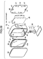
- Fig. 1 is an exploded perspective view of an ink container according to a first embodiment of the invention.
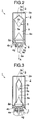
- Fig. 2 is a cross-sectional view of the ink container before the ink container is mounted to the ink jet head.
- Fig. 3 is a cross-sectional view of the ink container mounted to the ink jet head, after some of the ink has been used.
- an ink container includes a tank cover 2, and an ink bag 3 accommodated in the ink tank cover 2, and a tank base 4.
- the ink bag 3 includes ink bag elements 3a and 3b.
- the ink bag elements 3a and 3b are made of a film on which aluminum is vapor-deposited, or of a multilayer film that contains aluminum.
- the elements 3a and 3b are placed together in such a way that the ink bag elements 3a and 3b oppose each other to define a space therebetween having an opening at one end.
- the elements 3a and 3b are, for example, heat-welded together at their three sides for liquid tight seal.
- the ink bag 3 incorporates a spring 5 therein.
- the spring 5, which will be described later in detail, abuts inner surfaces of the opposed side walls of the ink bag elements 3a and 3b to urge the side walls in directions as to increase the volume of the ink bag 3.
- the opening of the ink bag 3 is connected to a tank base 4.
- the tank base 4 has two opposed surfaces, one 4a of which forming an inner surface 4a of the ink bag when the ink bag 3 has been assembled to the tank base, and the other 4b of which being exposed to the environment. Walls 4c rise from the inner surface 4a over which the ink bag 3 fits. Walls 4d also rise from the inner surface 4a to support the spring 5 thereon.
- the tank base 4 is formed with a through-hole 4e therein through which the interior of the ink bag 3 communicates with the environment, and a filter 6 (Fig. 2) placed on the inner surface 4a to close the through-hole 4e.
- the tank base 4 has an ink-filling hole, not shown, through which ink is filled after assembly of the ink container.
- the ink-filling hole is closed by a sealing cap. Then, a small amount of the ink is drawn through the through-hole 4e so that the spring 5 is deformed. Thereafter, the packing 8 is placed and is fixedly retained by the annular flange 4g. The ink bag 3 holds ink 9 therein and the ink 9 is supplied from the ink container 1 through the filter 6.
- the tank base 4 is formed with a stepped portion 4f all around the tank base 4 so that a tank cover 2 fittingly engages the tank base 4.
- the tank cover 2 is formed with a hole 2a therein through which air is introduced from the atmosphere as the ink is supplied from the ink container 1 to an external ink path 7.
- the spring 5 will be described in detail with reference to Figs. 4 and 5.
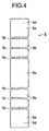
- Fig. 4 illustrates the spring 5 when expanded into a sheet.
- Fig. 5 illustrates the spring 5 when the sheet of Fig. 4 has been assembled into a three dimensional structure.
- the ink bag 3 holds both the spring 5 and ink 9 therein.
- the spring 5 is formed of, for example, a stainless steel or the like which is corrosion resistant and occupies a minimum space in the ink bag 3.
- the spring 5 includes two pressure-receiving members 5a, links 5b, and folded portions 5c that connect the pressure-receiving members 5a and the links 5b together and progressively are deformed as the ink 9 is supplied to the external device.
- the sheet shown in Fig. 4 is folded at portions 5c as shown in Fig. 5 and ends 5d are connected together at locations 5e by, for example, spot welding or laser welding.
- the folded portions 5c include a plurality of small straps spaced apart by a predetermined distance and connect links 5b to their adjacent links 5b, and flat part 5a to links 5b.
- the folded portions 5c have less rigidity than the pressure receiving members 5a and links 5b.
- Figs. 6 and 7 illustrate the characteristics of the spring 5 according to the first embodiment.
- Fig. 7 shows the relationship between the force F applied to the spring 5 and the deformation or compression ⁇ of the spring 5.
- the spring 5 will be further described with reference to Figs. 6 and 7.
- the spring 5 of Fig. 6 exhibits a characteristic represented by straight line A and curve B as the force F applied to the spring 5 is increased.
- Line A shows that the spring 5 is elastically deformed.
- Curve B implies that the spring 5 is in the plastic deformation region and therefore the spring will not regain its original shape after the force F has been removed.
- the force F is substantially constant in the plastic deformation region irrespective of the deformation ⁇ . If the force F is gradually decreased at point B1 in the plastic deformation region, the deformation decreases along dot-dash line C. It is to be noted that the spring 5 does not regain its original shape even after the force F has been decreased to zero, leaving a plastic deformation D. In other words, line C shows that the spring 5 still retains some resiliency after the spring 5 has entered its plastic deformation region.
- the force F decreases slightly as the deformation ⁇ increases in the vicinity of point B1 in the plastic deformation region. This occurs for the following reason.
- the deformation is concentrated on the folded portions 5c.
- the deformation of the folded portions 5c become larger as the deformation ⁇ increases so that angles between adjacent links 5b greatly varies (Fig. 6). Therefore, the forces act on the pressure-receiving members 5a, links 5b, and folded portions 5c in different ways from when the spring 5 is in the elastic deformation region.
- the magnitudes of deformation ⁇ and the force F at which the spring 5 enters from the elastic deformation region into the plastic deformation region can be adjusted at will by selecting the material and thickness of the spring 5, and the length and width of the folded portions 5c.
- Fig. 8 illustrates changes in the negative pressure of the ink container as the ink is supplied from the ink container to the external device.
- the spring 5 in the ink bag 3 is not compressed yet. After some amount of the ink 9 has been supplied from the ink container 1 to the external device, the ink bag 3 contracts in such a direction as to compress the spring 5. It is assumed in the embodiment that the initial compression of the spring 5 is on line A of Fig. 7, somewhat before the boundary between the elastic deformation region and the plastic deformation region. It is also assumed that the negative pressure of the ink container 1 is initially at point M and moves along curve E of Fig. 8 within a normal ejection region.
- the ink container 1 is coupled to the ink path 7 of the ink jet head and a printing is then performed.
- the ink bag 3 contracts (Fig. 3) as the remaining amount of the ink 9 decreases, the inner wall surfaces of the ink bag 3 causing the two pressure-receiving members 5a of the spring 5 to move toward each other.
- the biasing force of the spring 5 urges the inner wall of the ink bag 3 outwardly against the contraction force of the ink bag 3, thereby maintaining the negative pressure in the ink bag 3.
- the spring 5 eventually enters the plastic deformation region, i.e., the spring shifts from curve A to curve B.
- the biasing force of the spring 5 becomes smaller in the plastic deformation region than in the elastic deformation region.
- the force F in the plastic deformation region decreases only at a slow rate regardless of the deformation ⁇ , so that the negative pressure changes slowly at a minimum rate as shown by curve E.
- the spring 5 operates chiefly in its plastic deformation region during its useful lifetime.
- the spring force of the spring 5 retards the change in negative pressure in the ink container 1, thereby suppressing the changes in the negative pressure of the ink container 1.
- the width and length of the folded portion 5c and thickness of the material of the spring 5 can be carefully selected to adjust the rigidity of the spring 5, thereby achieving an optimum negative pressure of the ink container.
- the spring 5 can be of any shape and material as long as the spring 5 has the aforementioned properties and is liquid tight.
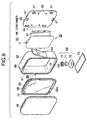
- Fig. 9 is an exploded perspective view of an ink container 51 according to a second embodiment.
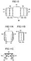
- Fig. 10 is an illustrative diagram of a spring according to the second embodiment before it is folded into a three-dimensional structure.
- Figs. 11A-11C are a top view, a side view, and a front view of the spring, respectively.
- Figs. 12 and 13 illustrate the properties of the spring.
- a frame 52 has a substantially rectangular cross-section and is a short cylinder in overall shape.
- the frame 52 forms a side wall of an ink container 51.
- the frame 52 has substantially rectangular openings at the opposed ends thereof, and is formed with a hole 53 therein that communicates with an ink outlet path 69.
- the ink outlet path 69 is connected to an ink-receiving path of the ink jet printer when the ink container 51 is mounted to the ink jet printer.
- One of the openings is closed by a flexible side wall 55 and the other is closed by a rigid wall 65.
- the frame 52 has a tongue 54 on its one outer surface.
- the tongue 54 serves to fix the ink container 51 when the ink container 51 is attached to the ink jet printer.
- the frame 52 is formed with a stepped portion 57 in the edge portion of one of the openings, the stepped portion 57 extending all around the opening.
- the flexible side wall 55 is a substantially rectangular in shape and has a periphery 56, which extends all around the flexible side wall 55 and is configured to the stepped portion of the frame 51.
- the side wall 55 is fixed at its periphery 56 to the stepped portion 57 by, for example, welding, thereby sealing the frame 52.
- the side wall 55 is of three-layer construction of polypropylene, deposited aluminum, and PET.
- the flat part 55a of the side wall 55 is of substantially the same shape as the opening of the frame 52 and somewhat smaller than the opening. Thus, the flat part 55a moves into the frame 52 as the ink is supplied to outside through the hole 53, so that the flat part 55a substantially closes the entire cross-section of the frame 52.
- the frame 52 is formed with a cutout 58 which opens to the atmosphere upon assembly of the entire ink container 1 (Fig. 16).
- the cross-sectional view of the side wall 55 of Fig. 9 is best shown in Figs. 16-18.
- a spring 59 is assembled in the frame 52 and sandwiched between the flexible side wall 55 and the rigid wall 65.
- the spring 59 is positioned so that it urges the flexible side wall 55 outwardly.
- the spring 59 includes a flat part 60, two dog-legged part 63a-63b and 63c-63d, folded portions 64 that connect the flat part 60, dog-legged parts 63a-63d, and feet 62 together.
- the spring 59 shown in Fig. 10 is folded into a three-dimensional structure shown in Fig. 11.
- the folded portions 64 has the smallest rigidity.
- the folded portions 64 may be formed in a narrow shape or may be made thinner than the other parts to achieve the smallest rigidity.
- the spring 59 is fixed to the rigid wall 65 with posts 66 extending through the holes 61 in the feet 62.
- the rigid wall 65 is formed with positioning ribs 67 thereon by which the rigid wall 65 is positioned with respect to the opening of the frame 52.
- the rigid wall 65 seals against the frame 52 so that the assembled structure is liquid tight.
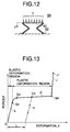
- Fig. 12 illustrates the spring 59 when the force F is applied with the feet 62 fixed.
- Fig. 13 illustrates the relationship between the force F and deformation ⁇ .
- the force F exerted on the spring 59 shown in Fig. 12 varies along curves E, G, and J.
- the curve G indicates that the spring 59 is in its plastic deformation region where the spring 59 will not regain to its original shape even if the force F is reduced to zero.
- the force F is substantially constant irrespective of the deformation ⁇ .
- the deformation ⁇ decreases along line H.
- line H shows that the spring 5 has not completely lost its resiliency after it has entered the plastic deformation region.
- the folded portions 64 are first deformed since the folded portions 64 have less rigidity than any other parts of the spring 5.
- the folded portions 64 have a narrow elastic deformation region.
- the force F increases as the deformation ⁇ increases (Fig. 13, point 0 to point G1).
- the folded portions 64 enter the plastic deformation region (Fig. 13, points G1-G2-G3-G4).
- the folded portions 64 are crushed completely with the result that the force F rapidly increases (Fig. 13, point G4-J1).
- a cover 68 is mounted to the ink container 51 to protect the side wall 55 from the environment.
- the cover 68 is welded to the stepped portion 57 of the frame 52.
- an inner space 90 defined between the cover 68 and the side wall 55 communicates with the atmosphere through the cutout 58 so that the air enters the space 90 in accordance with the movement of the side wall 55 toward the rigid wall 65.
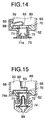
- FIGs. 14 and 15 are cross-sectional views of the ink outlet path 69 according to the second embodiment.
- the ink outlet path 69 includes a filter 70, a packing 71, and a cap 72.
- the cap 72 is fixedly mounted to the frame 52 by, for example, welding in order to hold the filter 70 and packing 71 in position.
- the packing 71 is in the shape of a hollow circular cylinder with a portion 71a in the shape of a frustum of a right circular cone that tapers inwardly of the cylinder.
- the portion 71a engages an inlet pipe 74a of an ink path 74 in a sealing relation when ink is supplied into the ink path 74.
- a sealing film 73 is fixedly mounted to the end of the cap 72 by, for example, welding, thereby providing a sealed environment for the ink until ready to use.
- the user peels off the sealing film 73 and the ink container 51 is coupled to an ink path 74 of the ink jet head.
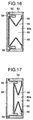
- Figs. 16-19 are cross-sectional views of the ink container 51, illustrating the operation of the ink container 51. The remaining ink decreases in the order of Figs. 16, 17, and 18.
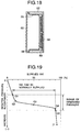
- Fig. 19 illustrates changes in the negative pressure of the ink container 51 as the ink is supplied into the ink path 74.
- Fig. 19 the negative pressure necessary for the ink to be supplied from the ink container 51 lies from point G1 to point G5.
- the ink 89 can be normally supplied from the ink container 51 when the negative pressure is between point G1 and point G4.
- Fig. 8 represents the characteristic after the pressure in the ink container 1 has reached a useable negative pressure while Fig. 19 shows the characteristic before and after the pressure in the ink container has reached a useable negative pressure.
- the spring 59 is assembled to the rigid wall 65 with no initial compressive load at all. Then, the cover 68 is fixedly assembled to the frame 52 so that the flat portion 60 of the spring 59 urges the side wall 55 outwardly. At this time, the characteristic of the spring 59 is between point G1 and point G2 where the spring 59 is in the plastic deformation region.
- the ink container 51 may be designed such that the spring 59 is initially between point 0 and point G1 where the spring 59 is in the elastic deformation region.
- the ink 89 is introduced into the ink-holding section 89a of the container 51 through an inlet, not shown, formed in a part of the frame 52 till there is no air in the ink holding section. When the ink holding section has just been filled with the ink 89, the pressure of the ink holding section ink 89 is the same as the atmospheric pressure (point 0 of Fig. 13).
- the ink-draining jig using an ink-draining jig, a certain amount of the ink 89 is drained from the ink container 51 to develop a negative pressure, thereby ensuring that the ink 89 is held in the ink-holding section 89a (Fig. 16, point G2 of Fig. 13).
- the ink-draining jig is removed, the ink in the ink outlet path 69 is sucked into the ink container 51 to the filter 70 shown in Fig. 14 due to the negative pressure, so that the surface tension of the filter 70 and the negative pressure in the ink-holding section 89a are balanced.
- the sealing film 73 is attached to seal the ink container 51.
- the cover 68 may be welded to the frame 52 after the negative pressure has been developed.
- the user Prior to using the ink in the ink container 51, the user peels off the sealing film 73 and then connects the ink container 51 to the ink path 74 as shown in Fig. 15. Then, the ink 89 is sucked from the ink container 51 through the ink path 74.
- the force F of the spring 59 changes along the curve G in the plastic deformation region shown Fig. 13 through points G2, G3, and G4, and the negative pressure in the ink container 51 changes along the curve shown in Fig. 19 through points G2, G3, and G4.
- the side wall 55 is compressed away from the cover 68 as the ink 89 decreases, causing the spring 59 to be compressed toward the rigid wall 65.
- the ink container 51 As the spring 59 is further compressed, the folded portions 64 are further plastically deformed. Finally, the spring 59 is completely collapsed as shown in Fig. 18, so that the force F exerted on the spring 59 rapidly increases along line J from point G4 to point J1 as shown in Fig. 13. As a result, the negative pressure characteristic of the ink container 51 changes from point G4 to point J1 of Fig. 19 beyond the range of demanded pressure, failing to supply ink any further. Thus, the ink container 51 reaches the end of its life and there is little or no ink 89 left in the ink container 51.
- the spring 59 plastically deforms to be permanently crushed, and therefore even if the ink container 51 is again filled with the ink 89, the negative pressure will not be developed again.
- the spring 59 is of the construction where the spring 59 is in the plastic deformation region when the ink is normally supplied into the ink path 74.
- the construction is capable of suppressing changes in the negative pressure in the ink container 51 as the remaining ink decreases, so that changes in the negative pressure are minimized till the ink has nearly been exhausted.
- the negative pressure can easily be set to a desired value by selecting the shape of the spring 59, thereby improving ink-utilizing efficiency of the ink container 51.
- the ink container 51 cannot be refilled, preventing the user from using ink that is not accepted to the ink container. This prevents troubles of the printhead resulting from the use of non-accepted ink.
- the ink container 51 according to the second embodiment is easy to assemble compared to the ink container 1 according to the first embodiment.
- the spring 59 has been in the plastic deformation region before the ink container 51 starts to supply ink.
- the ink container 51 may be designed so that the spring 59 is still in the elastic deformation region as long as the negative pressure is such that the ink 89 may be held in the container 51.
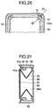
- Fig. 20 illustrates a part of an ink container according to a third embodiment.
- Fig. 21 is a cross-sectional view of the ink container according to the third embodiment.
- the side wall 55 of the second embodiment is formed from a flat sheet material, which is folded into a three dimensional structure.
- the side wall 55 is fixedly connected at its periphery to the stepped portion 57 of the frame 52 by, for example, welding.
- the corners of the side wall 55 are wrinkled as shown in Fig. 20.
- These wrinkles 75 become more stiff than the other parts of the side wall 55, resisting against the deformation of the side wall 55 when the flat part 55a of the side wall 55 is displaced into the ink container 51 as shown in Figs. 16-18.
- the inner wall 88 of the frame 52 and the flat portion 60 of the spring 59 may be spaced apart by a larger distance, but the ink holding capacity of the ink container will be decreased.
- the third embodiment solves the drawback of the second embodiment.
- the corner radius R1 of the inner wall 88 and the corner radius R2 of the flat portion 60 are related by Equation (1) as follows: R2 ⁇ R1
- the side wall 55 is made of a very soft, flexible material so that the side wall 55 is configured to the shape of the flat part 60 of the spring 59.
- the side wall 55 that covers the corners of the flat part 60 of the spring 59 is gradually curved, alleviating the adverse effect of the wrinkles 75 on the deformation of the side wall 55.
- Equation (1) provides a sufficient space in which the areas of the side wall 55 near the wrinkles 75 can be smoothly deformed, so that the somewhat rigid wrinkles 75 will not significantly affect the change in negative pressure.
- Equation (1) alleviates the adverse effect of the wrinkles 75 on changes in negative pressure without substantially spacing the edges 60a of the flat part 60 of the spring 59 apart from the edges 52a of the frame 52.
- the corners of the flat part 60 may be chamfered, a combination of obtuse angles, or a combination of an arcuate shape and obtuse angles.
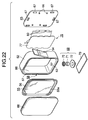
- Fig. 22 is an exploded perspective view of an ink container according to a fourth embodiment.
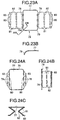
- Fig. 23A illustrates a spring as it is stamped from a sheet material.
- Fig. 23B is a fragmentary cross-sectional view taken along the lines 23B-23B of Fig. 23A.
- Figs. 24A-24C are a top view, a side view, and a front view of the spring.
- the ink container 51 according to the second embodiment is of the construction where the interior of the ink container 51 is maintained negative in pressure. Therefore the side wall 55 is pressed at all times against entire the flat part 60 including the peripheral edge portion of the flat part 60 and the edge portions of the folded portions 64. Therefore, the side wall 55 may be broken due to vibration and long term storage.
- a spring 76 is shaped as shown in Figs. 22-24.
- the flat part 77 is continuous with connectors 81 via a plurality of first folded portions 78.
- the flat part 77 has a cutout 78a on both sides of each of the first folded portions 78, so that the first folded portions 78 are behind the outer edge of the flat part 77 of the spring 76 as shown in Fig. 23.
- the flat part 77 has a roll over 79 formed all around the periphery by, for example, drawing except the folded portions 78 and cutouts 78a.
- the roll over 79 is rolled downward away from the flat part 77 so that when the ink container has been assembled, the outer edge of the roll over 79 will not be in contact with the flat part 55a of the side wall 55.
- the spring 76 further includes holes 80, connectors 81, second folded portions 82, and feet 83, which are of the same construction as those of the second embodiment and the description thereof are omitted.
- the rest of the construction of the ink container 51 is the same as that of the second embodiment.
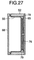
- FIGs. 25-27 are cross-sectional views illustrating the operation of the ink container according to the fourth embodiment.
- the roll over 79 prevents the side wall 55 from pressing the sharp edge of the flat part 77 of the spring 76.
- the edges of the first folded portions 78 are located behind the roll over 79 so that the side wall 55 is not pressed against the edges of the first folded portions 78.
- Fig. 28 is an exploded perspective view of an ink container according to a fifth embodiment.
- Fig. 29 is a cross-sectional view of the ink outlet path of the ink container 51.
- the side wall 55 is urged inwardly toward the rigid wall 65 as the ink 89 is supplied into the ink path 74. Then, the side wall 55 may close the hole 53, blocking normal ink flow through the hole 53.
- the inner wall 88 of the frame 84 is provided with ribs 86 which surround a hole 85 and extend in a direction in which the side wall 55 is displaced into the frame 84.
- the ribs 86 prevent the side wall 55 from completely closing the hole 85, providing ink paths even if the side wall 55 is displaced over the hole 85.
- the shape of the spring 76 is the same as that of the fourth embodiment.
- the frame 84 has corners with a radius R1 and the flat part 77 of the spring 76 has corners with a radius R2, given by Equation (1), i.e., R2 ⁇ R1.
- R2 ⁇ R1 the radius of the spring 76
- the side wall 55 is compressed as the ink is supplied into the ink path 74.
- the side wall 55 then passes over the hole 85.
- the ribs 86 keep the side wall 55 away from the hole 85 ensuring paths for the ink 89 to flow into the hole 85.
- the ink 89 continues to be smoothly supplied to the ink jet head until the ink 89 is completely exhausted.
- the inner wall 88 of the frame 84 may be formed with a plurality of grooves extending in a direction in which the side wall 55 is compressed.
- a plurality of projections may be provided around the hole 85 to keep the side wall 55 a predetermined distance away from the hole 85, thereby ensuring the path for the ink 89 to flow into the hole 85.
- the present invention has been described with reference to an ink container for use in ink jet printers, the invention may be applicable to any liquid containers which hold a liquid therein and supplies the liquid in accordance with the suction operation from outside.
Landscapes
- Ink Jet (AREA)
Abstract
Description
- The present invention relates to an ink container that is kept at a pressure lower than the atmosphere to hold ink.
- With ink containers for use in on-demand type ink jet printers, various constructions have been proposed for maintaining the interior of the ink container at a negative pressure with respect to the atmospheric pressure. One such conventional ink container is of the construction that an ink absorbing material is accommodated in the ink container and the negative pressure of the ink absorbing material serves to hold ink therein. However, this construction is not effective in utilizing a limited space of the container. One of the most effective constructions appears to be one that the ink container is sealed against the atmosphere and a negative pressure in the container serves to hold ink in the container.
- Constant negative pressure in the ink container is one of the important characteristics required of this type of ink container. However, the negative pressure in the ink container varies in accordance with the remaining amount of ink and environmental conditions such as temperature and atmospheric pressure. Therefore, a variety of constructions for the negative-pressure type ink container have been proposed in order to maintain as constant a negative pressure as possible.
- For example, Japanese patent Preliminary Publication KOKAI) No. 6-226993 discloses a liquid ink cartridge that includes an ink container with a pair of resilient side walls. The ink container accommodates a metal spring therein, which urges the side walls from the inner side to the outside of the ink container. The inside of the ink container is maintained at a negative pressure. With ink containers of the construction, the resilient side walls deform inwardly to compress the spring as the ink is supplied to an external device, thereby gradually decreasing the volume of the ink container. Thus, the construction does not allow air to enter the ink container from outside, thereby significantly reducing effects of the environmental changes such as temperature and atmospheric pressure on the negative pressure in the ink container.
- With the aforementioned conventional ink container, the spring simply deforms resiliently. When the side walls exert forces on the spring in such a direction as to compress the spring, the force of the spring acting on the side walls proportionally increases. If the negative pressure increases beyond a predetermined value, the ink is sucked inwardly too strongly, so that the ink cannot be ejected properly or not ejected at all.
- One of the solutions to this problem is to reduce the spring constant of the spring, thereby decreasing changes in negative pressure. However, this approach requires a large initial deformation of the spring in order to achieve an initial negative pressure of the ink container. Therefore, the volume of the ink container cannot be effectively used.
- An object of the invention is to provide an ink container whose ink-holding space is maintained at a substantially constant negative pressure until the ink contained in the ink-holding space has been exhausted.
- An ink container (1, 51) has an ink-holding space (9a, 89) which holds ink (89) therein. The pressure in the ink-holding space is held negative with respect to an atmospheric pressure. The ink container includes a flexible wall (3, 55) and an urging member (5, 59, 76). The flexible wall (3, 55) forms a part of the ink-holding space. The urging member takes the form of, for example, a spring. The urging member (5, 59, 76) is incorporated in the ink-holding space and urges the flexible wall (3, 55) outwardly of the ink-holding space. An atmospheric pressure is exerted on the flexible wall (3, 55) so that the flexible wall (3, 55) is displaceable inwardly of the ink-holding space as the ink is supplied from the ink-holding space to an external device. The urging member (5, 59, 76) operates substantially in a plastic deformation region thereof.
- Another ink container includes a frame (52, 84), a flexible wall (55), and an urging member (59, 77). The frame (52, 84) defines an ink-holding space which holds ink (89) therein. The pressure in the ink-holding space is held negative with respect to an atmospheric pressure. The flexible wall (55) forms a part of the ink-holding space and one side thereof receives the atmospheric pressure. The flexible wall (55) has a periphery (56) securely assembled to the frame to close the ink-holding space. The flexible wall (55) is displaced inwardly of the ink-holding space as the ink (89) is supplied from the ink-holding space to an external device. The urging member (59, 77) is incorporated in the ink-holding space and urges the flexible wall (55) outwardly of the ink-holding space. The urging member (59, 77) is substantially in a plastic deformation region thereof.
- Further scope of applicability of the present invention will become apparent from the detailed description given hereinafter. However, it should be understood that the detailed description and specific examples, while indicating preferred embodiments of the invention, are given by way of illustration only, since various changes and modifications within the spirit and scope of the invention will become apparent to those skilled in the art from this detailed description.
- The present invention will become more fully understood from the detailed description given hereinbelow and the accompanying drawings which are given by way of illustration only, and thus are not limitative of the present invention, and wherein:
- Fig. 1 is an exploded perspective view of an ink container according to a first embodiment;
- Fig. 2 is a cross-sectional view of the ink container of the first embodiment before the ink container is mounted to the ink jet head;
- Fig. 3 is a cross-sectional view of the ink container mounted to the ink jet head, after some of the ink has been used;
- Fig. 4 illustrates the spring of the first embodiment when expanded into a sheet;
- Fig. 5 illustrates the spring of the first embodiment when assembled into a three dimensional structure;
- Figs. 6 and 7 illustrate the characteristics of the spring the first embodiment;
- Fig. 8 illustrates changes in the negative pressure of the ink container as the ink is supplied from the ink container to an external ink path;
- Fig. 9 is an exploded perspective view of an ink container according to a second embodiment;
- Fig. 10 is an illustrative diagram of a spring of the second embodiment before it is folded into a structure;
- Figs. 11A-11C are a top view, a side view, and a front view of the spring of the second embodiment, respectively;
- Figs. 12 and 13 illustrates the properties of the spring of the second embodiment;
- Figs. 14 and 15 are cross-sectional views of an ink outlet path according to the second embodiment;
- Figs. 16-18 are cross-sectional views of the ink container, illustrating the operation of the ink container;
- Fig. 19 illustrates changes in the negative pressure of the ink container according to the second embodiment as the ink is supplied from the ink container to an external ink path;
- Fig. 20 illustrates a part of an ink container according to a third embodiment;
- Fig. 21 is a cross-sectional view of the ink container of the third embodiment;
- Fig. 22 is an exploded perspective view of an ink container according to a fourth embodiment;
- Fig. 23A illustrates a spring of the fourth embodiment as it is stamped from a sheet material;
- Fig. 23B is a fragmentary cross-sectional view taken along
the
lines 23B-23B of Fig. 23A; - Figs. 24A-24C are a top view, a front view, and a side view of the spring of the fourth embodiment, respectively;
- Figs. 25-27 are cross-sectional views illustrating the operation of the ink container according to the fourth embodiment;
- Fig. 28 is an exploded perspective view of an ink container according to a fifth embodiment; and
- Fig. 29 is a cross-sectional view of the ink outlet path of the ink container of Fig. 28.
-
- Embodiments of the present invention will be described in detail with reference to the accompanying drawings.
- Fig. 1 is an exploded perspective view of an ink container according to a first embodiment of the invention.
- Fig. 2 is a cross-sectional view of the ink container before the ink container is mounted to the ink jet head.
- Fig. 3 is a cross-sectional view of the ink container mounted to the ink jet head, after some of the ink has been used.
- Referring to Fig. 1, an ink container includes a
tank cover 2, and anink bag 3 accommodated in theink tank cover 2, and atank base 4. - The
ink bag 3 includesink bag elements ink bag elements elements ink bag elements elements ink bag 3 incorporates aspring 5 therein. Thespring 5, which will be described later in detail, abuts inner surfaces of the opposed side walls of theink bag elements ink bag 3. The opening of theink bag 3 is connected to atank base 4. - The
tank base 4 has two opposed surfaces, one 4a of which forming aninner surface 4a of the ink bag when theink bag 3 has been assembled to the tank base, and the other 4b of which being exposed to the environment.Walls 4c rise from theinner surface 4a over which theink bag 3 fits.Walls 4d also rise from theinner surface 4a to support thespring 5 thereon. Thetank base 4 is formed with a through-hole 4e therein through which the interior of theink bag 3 communicates with the environment, and a filter 6 (Fig. 2) placed on theinner surface 4a to close the through-hole 4e. Thetank base 4 has an ink-filling hole, not shown, through which ink is filled after assembly of the ink container. After filling the ink, the ink-filling hole is closed by a sealing cap. Then, a small amount of the ink is drawn through the through-hole 4e so that thespring 5 is deformed. Thereafter, thepacking 8 is placed and is fixedly retained by theannular flange 4g. Theink bag 3 holdsink 9 therein and theink 9 is supplied from the ink container 1 through thefilter 6. - When the
tab 8a is pulled outwardly in a direction shown by arrow A, the throughhole 4e opens. - The
tank base 4 is formed with a steppedportion 4f all around thetank base 4 so that atank cover 2 fittingly engages thetank base 4. Thetank cover 2 is formed with ahole 2a therein through which air is introduced from the atmosphere as the ink is supplied from the ink container 1 to an external ink path 7. - The
spring 5 will be described in detail with reference to Figs. 4 and 5. - Fig. 4 illustrates the
spring 5 when expanded into a sheet. - Fig. 5 illustrates the
spring 5 when the sheet of Fig. 4 has been assembled into a three dimensional structure. - As described above, the
ink bag 3 holds both thespring 5 andink 9 therein. Thespring 5 is formed of, for example, a stainless steel or the like which is corrosion resistant and occupies a minimum space in theink bag 3. Thespring 5 includes two pressure-receivingmembers 5a,links 5b, and foldedportions 5c that connect the pressure-receivingmembers 5a and thelinks 5b together and progressively are deformed as theink 9 is supplied to the external device. The sheet shown in Fig. 4 is folded atportions 5c as shown in Fig. 5 and ends 5d are connected together atlocations 5e by, for example, spot welding or laser welding. - The folded
portions 5c include a plurality of small straps spaced apart by a predetermined distance and connectlinks 5b to theiradjacent links 5b, andflat part 5a tolinks 5b. Thus, the foldedportions 5c have less rigidity than thepressure receiving members 5a andlinks 5b. When a pressure is exerted on thespring 5 in such directions that the pressure-receivingmembers 5a are pressed toward each other, the foldedportions 5c are further deformed. - Figs. 6 and 7 illustrate the characteristics of the
spring 5 according to the first embodiment. Fig. 7 shows the relationship between the force F applied to thespring 5 and the deformation or compression δ of thespring 5. Thespring 5 will be further described with reference to Figs. 6 and 7. - As shown in Fig. 7, the
spring 5 of Fig. 6 exhibits a characteristic represented by straight line A and curve B as the force F applied to thespring 5 is increased. Line A shows that thespring 5 is elastically deformed. In other words, the compression δ is proportional to the force F applied to thespring 5, i.e.,spring 5 is in the plastic deformation region and therefore the spring will not regain its original shape after the force F has been removed. - As is clear from Curve B, the force F is substantially constant in the plastic deformation region irrespective of the deformation δ . If the force F is gradually decreased at point B1 in the plastic deformation region, the deformation decreases along dot-dash line C. It is to be noted that the
spring 5 does not regain its original shape even after the force F has been decreased to zero, leaving a plastic deformation D. In other words, line C shows that thespring 5 still retains some resiliency after thespring 5 has entered its plastic deformation region. - Further, the force F decreases slightly as the deformation δ increases in the vicinity of point B1 in the plastic deformation region. This occurs for the following reason. The deformation is concentrated on the folded
portions 5c. The deformation of the foldedportions 5c become larger as the deformation δ increases so that angles betweenadjacent links 5b greatly varies (Fig. 6). Therefore, the forces act on the pressure-receivingmembers 5a,links 5b, and foldedportions 5c in different ways from when thespring 5 is in the elastic deformation region. - The magnitudes of deformation δ and the force F at which the
spring 5 enters from the elastic deformation region into the plastic deformation region can be adjusted at will by selecting the material and thickness of thespring 5, and the length and width of the foldedportions 5c. - The operation of the ink container with the aforementioned spring built in will be described in terms of the operation of changes in negative pressure with reference to Fig. 8. Fig. 8 illustrates changes in the negative pressure of the ink container as the ink is supplied from the ink container to the external device.
- When the
ink bag 3 has just been filled withink 9, thespring 5 in theink bag 3 is not compressed yet. After some amount of theink 9 has been supplied from the ink container 1 to the external device, theink bag 3 contracts in such a direction as to compress thespring 5. It is assumed in the embodiment that the initial compression of thespring 5 is on line A of Fig. 7, somewhat before the boundary between the elastic deformation region and the plastic deformation region. It is also assumed that the negative pressure of the ink container 1 is initially at point M and moves along curve E of Fig. 8 within a normal ejection region. - The ink container 1 is coupled to the ink path 7 of the ink jet head and a printing is then performed. The
ink bag 3 contracts (Fig. 3) as the remaining amount of theink 9 decreases, the inner wall surfaces of theink bag 3 causing the two pressure-receivingmembers 5a of thespring 5 to move toward each other. At this time, the biasing force of thespring 5 urges the inner wall of theink bag 3 outwardly against the contraction force of theink bag 3, thereby maintaining the negative pressure in theink bag 3. When theink bag 3 further contracts as a result of continued printing operation, thespring 5 eventually enters the plastic deformation region, i.e., the spring shifts from curve A to curve B. - The biasing force of the
spring 5 becomes smaller in the plastic deformation region than in the elastic deformation region. The force F in the plastic deformation region decreases only at a slow rate regardless of the deformation δ , so that the negative pressure changes slowly at a minimum rate as shown by curve E. - If the
spring 5 remains in the elastic deformation region shown by curve A in Fig. 7 just as in the conventional art, then the negative pressure will change along the straight portion G of a dash-dash curve in Fig. 8. As theink bag 3 contracts, the biasing force F of thespring 5 increases proportionally, so that the negative pressure of in the ink container 1 increases more rapidly than curve E. As a result, the negative pressure in the ink container 1 increases beyond the normal ejection region before theink 9 in theink bag 3 has been exhausted, leaving some unused ink in theink bag 3. - In the aforementioned first embodiment, the
spring 5 operates chiefly in its plastic deformation region during its useful lifetime. Thus, when thespring 5 plastically deforms as theink 9 is supplied into the ink path of the ink jet head, the spring force of thespring 5 retards the change in negative pressure in the ink container 1, thereby suppressing the changes in the negative pressure of the ink container 1. - The changes in the volume of the ink container 1 and environmental conditions such as temperature and atmospheric pressure cause changes in the force F applied by the
ink bag 3 and changes in the negative pressure of the ink container 1. Therefore, the width and length of the foldedportion 5c and thickness of the material of thespring 5 can be carefully selected to adjust the rigidity of thespring 5, thereby achieving an optimum negative pressure of the ink container. - The
spring 5 can be of any shape and material as long as thespring 5 has the aforementioned properties and is liquid tight. - Fig. 9 is an exploded perspective view of an
ink container 51 according to a second embodiment. - Fig. 10 is an illustrative diagram of a spring according to the second embodiment before it is folded into a three-dimensional structure.
- Figs. 11A-11C are a top view, a side view, and a front view of the spring, respectively.
- Figs. 12 and 13 illustrate the properties of the spring.
- Referring to Fig. 9, a
frame 52 has a substantially rectangular cross-section and is a short cylinder in overall shape. Theframe 52 forms a side wall of anink container 51. Theframe 52 has substantially rectangular openings at the opposed ends thereof, and is formed with ahole 53 therein that communicates with anink outlet path 69. Theink outlet path 69 is connected to an ink-receiving path of the ink jet printer when theink container 51 is mounted to the ink jet printer. One of the openings is closed by aflexible side wall 55 and the other is closed by arigid wall 65. Theframe 52 has atongue 54 on its one outer surface. Thetongue 54 serves to fix theink container 51 when theink container 51 is attached to the ink jet printer. Theframe 52 is formed with a steppedportion 57 in the edge portion of one of the openings, the steppedportion 57 extending all around the opening. - The
flexible side wall 55 is a substantially rectangular in shape and has aperiphery 56, which extends all around theflexible side wall 55 and is configured to the stepped portion of theframe 51. Theside wall 55 is fixed at itsperiphery 56 to the steppedportion 57 by, for example, welding, thereby sealing theframe 52. Theside wall 55 is of three-layer construction of polypropylene, deposited aluminum, and PET. Theflat part 55a of theside wall 55 is of substantially the same shape as the opening of theframe 52 and somewhat smaller than the opening. Thus, theflat part 55a moves into theframe 52 as the ink is supplied to outside through thehole 53, so that theflat part 55a substantially closes the entire cross-section of theframe 52. Theframe 52 is formed with acutout 58 which opens to the atmosphere upon assembly of the entire ink container 1 (Fig. 16). The cross-sectional view of theside wall 55 of Fig. 9 is best shown in Figs. 16-18. - A
spring 59 is assembled in theframe 52 and sandwiched between theflexible side wall 55 and therigid wall 65. Thespring 59 is positioned so that it urges theflexible side wall 55 outwardly. Referring to Fig. 10 and 11A-11C, thespring 59 includes aflat part 60, two dog-legged part 63a-63b and 63c-63d, foldedportions 64 that connect theflat part 60, dog-legged parts 63a-63d, andfeet 62 together. - The
spring 59 shown in Fig. 10 is folded into a three-dimensional structure shown in Fig. 11. Of theflat part 60, twofeet 62,doglegged parts 63a-63b and 63c-63d, and foldedportions 64, the foldedportions 64 has the smallest rigidity. The foldedportions 64 may be formed in a narrow shape or may be made thinner than the other parts to achieve the smallest rigidity. - The
spring 59 is fixed to therigid wall 65 withposts 66 extending through theholes 61 in thefeet 62. Therigid wall 65 is formed with positioningribs 67 thereon by which therigid wall 65 is positioned with respect to the opening of theframe 52. Therigid wall 65 seals against theframe 52 so that the assembled structure is liquid tight. - The characteristics of the
spring 59 will now be described. Fig. 12 illustrates thespring 59 when the force F is applied with thefeet 62 fixed. Fig. 13 illustrates the relationship between the force F and deformation δ . When a force is exerted on theflat portion 60 of the assembledspring 59 in such a direction as to compress the spring causes thespring 59, the deformation δ is concentrated on the foldedportions 64. - The force F exerted on the
spring 59 shown in Fig. 12 varies along curves E, G, and J. The straight portion of line E indicates that thespring 59 is in its elastic deformation region where the force F is proportional to the deformation δ, i.e.,spring 59 is in its plastic deformation region where thespring 59 will not regain to its original shape even if the force F is reduced to zero. When the spring is on line J, thespring 59 is completely broken. - In the plastic deformation region as shown by curve G, the force F is substantially constant irrespective of the deformation δ. When the force F is reduced gradually at point G3 in the middle of the plastic deformation region, the deformation δ decreases along line H. The deformation will reach δ=L after the force F has been reduced to zero. In other words, line H shows that the
spring 5 has not completely lost its resiliency after it has entered the plastic deformation region. - When the force F acts on the
flat part 60 of thespring 5 as shown in Fig. 12, the foldedportions 64 are first deformed since the foldedportions 64 have less rigidity than any other parts of thespring 5. The foldedportions 64 have a narrow elastic deformation region. The force F increases as the deformation δ increases (Fig. 13,point 0 to point G1). When the force F further increases, the foldedportions 64 enter the plastic deformation region (Fig. 13, points G1-G2-G3-G4). When the force F increases still further, the foldedportions 64 are crushed completely with the result that the force F rapidly increases (Fig. 13, point G4-J1). - In the first embodiment, as shown in Fig. 7, when the
spring 5 is in the plastic deformation region, the force F gradually decreases with increasing deformation δ. In the second embodiment shown in Fig. 13, when thespring 5 is in the plastic deformation region, the force F gradually increases as the deformation δ increases. This is because thesprings - Referring again to Fig. 9, a
cover 68 is mounted to theink container 51 to protect theside wall 55 from the environment. Thecover 68 is welded to the steppedportion 57 of theframe 52. Upon assembling thecover 68 to theframe 52, aninner space 90 defined between thecover 68 and theside wall 55 communicates with the atmosphere through thecutout 58 so that the air enters thespace 90 in accordance with the movement of theside wall 55 toward therigid wall 65. - The
ink outlet path 69 of theink container 51 will be described. Figs. 14 and 15 are cross-sectional views of theink outlet path 69 according to the second embodiment. - Referring to Fig. 14, the
ink outlet path 69 includes afilter 70, a packing 71, and acap 72. Thecap 72 is fixedly mounted to theframe 52 by, for example, welding in order to hold thefilter 70 and packing 71 in position. The packing 71 is in the shape of a hollow circular cylinder with aportion 71a in the shape of a frustum of a right circular cone that tapers inwardly of the cylinder. Theportion 71a engages aninlet pipe 74a of anink path 74 in a sealing relation when ink is supplied into theink path 74. A sealingfilm 73 is fixedly mounted to the end of thecap 72 by, for example, welding, thereby providing a sealed environment for the ink until ready to use. - Referring to Fig. 15, immediately before using the ink, the user peels off the sealing
film 73 and theink container 51 is coupled to anink path 74 of the ink jet head. - The operation of the
ink container 51 will be described with reference to Figs. 16-19 with respect to changes in negative pressure in theink container 51 when the ink is drawn from theink container 51 into theink path 74.
Figs. 16-18 are cross-sectional views of theink container 51, illustrating the operation of theink container 51. The remaining ink decreases in the order of Figs. 16, 17, and 18. Fig. 19 illustrates changes in the negative pressure of theink container 51 as the ink is supplied into theink path 74. - Referring to Fig. 19, the negative pressure necessary for the ink to be supplied from the
ink container 51 lies from point G1 to point G5. Theink 89 can be normally supplied from theink container 51 when the negative pressure is between point G1 and point G4. It is to be noted that Fig. 8 (first embodiment) represents the characteristic after the pressure in the ink container 1 has reached a useable negative pressure while Fig. 19 shows the characteristic before and after the pressure in the ink container has reached a useable negative pressure. - The
spring 59 is assembled to therigid wall 65 with no initial compressive load at all. Then, thecover 68 is fixedly assembled to theframe 52 so that theflat portion 60 of thespring 59 urges theside wall 55 outwardly. At this time, the characteristic of thespring 59 is between point G1 and point G2 where thespring 59 is in the plastic deformation region. Of course, theink container 51 may be designed such that thespring 59 is initially betweenpoint 0 and point G1 where thespring 59 is in the elastic deformation region. Theink 89 is introduced into the ink-holdingsection 89a of thecontainer 51 through an inlet, not shown, formed in a part of theframe 52 till there is no air in the ink holding section. When the ink holding section has just been filled with theink 89, the pressure of the ink holdingsection ink 89 is the same as the atmospheric pressure (point 0 of Fig. 13). - Then, using an ink-draining jig, a certain amount of the
ink 89 is drained from theink container 51 to develop a negative pressure, thereby ensuring that theink 89 is held in the ink-holdingsection 89a (Fig. 16, point G2 of Fig. 13). When the ink-draining jig is removed, the ink in theink outlet path 69 is sucked into theink container 51 to thefilter 70 shown in Fig. 14 due to the negative pressure, so that the surface tension of thefilter 70 and the negative pressure in the ink-holdingsection 89a are balanced. Then, the sealingfilm 73 is attached to seal theink container 51. - The
cover 68 may be welded to theframe 52 after the negative pressure has been developed. - Prior to using the ink in the
ink container 51, the user peels off the sealingfilm 73 and then connects theink container 51 to theink path 74 as shown in Fig. 15. Then, theink 89 is sucked from theink container 51 through theink path 74. - As the
ink 89 is supplied from theink container 51 through theink path 74, the force F of thespring 59 changes along the curve G in the plastic deformation region shown Fig. 13 through points G2, G3, and G4, and the negative pressure in theink container 51 changes along the curve shown in Fig. 19 through points G2, G3, and G4. As shown in Fig. 17, theside wall 55 is compressed away from thecover 68 as theink 89 decreases, causing thespring 59 to be compressed toward therigid wall 65. - As the
spring 59 is further compressed, the foldedportions 64 are further plastically deformed. Finally, thespring 59 is completely collapsed as shown in Fig. 18, so that the force F exerted on thespring 59 rapidly increases along line J from point G4 to point J1 as shown in Fig. 13. As a result, the negative pressure characteristic of theink container 51 changes from point G4 to point J1 of Fig. 19 beyond the range of demanded pressure, failing to supply ink any further. Thus, theink container 51 reaches the end of its life and there is little or noink 89 left in theink container 51. - The
spring 59 plastically deforms to be permanently crushed, and therefore even if theink container 51 is again filled with theink 89, the negative pressure will not be developed again. - In the second embodiment, the
spring 59 is of the construction where thespring 59 is in the plastic deformation region when the ink is normally supplied into theink path 74. The construction is capable of suppressing changes in the negative pressure in theink container 51 as the remaining ink decreases, so that changes in the negative pressure are minimized till the ink has nearly been exhausted. The negative pressure can easily be set to a desired value by selecting the shape of thespring 59, thereby improving ink-utilizing efficiency of theink container 51. - The
ink container 51 cannot be refilled, preventing the user from using ink that is not accepted to the ink container. This prevents troubles of the printhead resulting from the use of non-accepted ink. - The
ink container 51 according to the second embodiment is easy to assemble compared to the ink container 1 according to the first embodiment. - In the second embodiment, the
spring 59 has been in the plastic deformation region before theink container 51 starts to supply ink. Alternatively, theink container 51 may be designed so that thespring 59 is still in the elastic deformation region as long as the negative pressure is such that theink 89 may be held in thecontainer 51. - Fig. 20 illustrates a part of an ink container according to a third embodiment. Fig. 21 is a cross-sectional view of the ink container according to the third embodiment.
- Referring back to Fig. 9, the
side wall 55 of the second embodiment is formed from a flat sheet material, which is folded into a three dimensional structure. Theside wall 55 is fixedly connected at its periphery to the steppedportion 57 of theframe 52 by, for example, welding. As a result, the corners of theside wall 55 are wrinkled as shown in Fig. 20. Thesewrinkles 75 become more stiff than the other parts of theside wall 55, resisting against the deformation of theside wall 55 when theflat part 55a of theside wall 55 is displaced into theink container 51 as shown in Figs. 16-18. This causes changes in negative pressure. In order to reduce the effects of thewrinkles 75 on the negative pressure, theinner wall 88 of theframe 52 and theflat portion 60 of thespring 59 may be spaced apart by a larger distance, but the ink holding capacity of the ink container will be decreased. - The third embodiment solves the drawback of the second embodiment. In the third embodiment, the corner radius R1 of the
inner wall 88 and the corner radius R2 of theflat portion 60 are related by Equation (1) as follows: - The
side wall 55 is made of a very soft, flexible material so that theside wall 55 is configured to the shape of theflat part 60 of thespring 59. By satisfying Equation (1), theside wall 55 that covers the corners of theflat part 60 of thespring 59 is gradually curved, alleviating the adverse effect of thewrinkles 75 on the deformation of theside wall 55. - The rest of the construction is the same as that of the second embodiment.
- The operation of the
side wall 55 when the ink is supplied from theink container 51 will be described. - As shown in Figs. 16-18, the
side wall 55 is gradually compressed toward therigid wall 65 as the remaining ink decreases. Equation (1) provides a sufficient space in which the areas of theside wall 55 near thewrinkles 75 can be smoothly deformed, so that the somewhatrigid wrinkles 75 will not significantly affect the change in negative pressure. - Equation (1) alleviates the adverse effect of the
wrinkles 75 on changes in negative pressure without substantially spacing theedges 60a of theflat part 60 of thespring 59 apart from the edges 52a of theframe 52. - Instead of an arcuate shape, the corners of the
flat part 60 may be chamfered, a combination of obtuse angles, or a combination of an arcuate shape and obtuse angles. Fourth embodiment - Fig. 22 is an exploded perspective view of an ink container according to a fourth embodiment. Fig. 23A illustrates a spring as it is stamped from a sheet material. Fig. 23B is a fragmentary cross-sectional view taken along the
lines 23B-23B of Fig. 23A. Figs. 24A-24C are a top view, a side view, and a front view of the spring. - The
ink container 51 according to the second embodiment is of the construction where the interior of theink container 51 is maintained negative in pressure. Therefore theside wall 55 is pressed at all times against entire theflat part 60 including the peripheral edge portion of theflat part 60 and the edge portions of the foldedportions 64. Therefore, theside wall 55 may be broken due to vibration and long term storage. - To prevent such a problem, a
spring 76 according to the fourth embodiment is shaped as shown in Figs. 22-24. In other words, theflat part 77 is continuous withconnectors 81 via a plurality of first foldedportions 78. Theflat part 77 has acutout 78a on both sides of each of the first foldedportions 78, so that the first foldedportions 78 are behind the outer edge of theflat part 77 of thespring 76 as shown in Fig. 23. - The
flat part 77 has a roll over 79 formed all around the periphery by, for example, drawing except the foldedportions 78 andcutouts 78a. The roll over 79 is rolled downward away from theflat part 77 so that when the ink container has been assembled, the outer edge of the roll over 79 will not be in contact with theflat part 55a of theside wall 55. Thespring 76 further includesholes 80,connectors 81, second foldedportions 82, andfeet 83, which are of the same construction as those of the second embodiment and the description thereof are omitted. The rest of the construction of theink container 51 is the same as that of the second embodiment. - The operation of the
ink container 51 will now be described with respect to that different from the second embodiment. Figs. 25-27 are cross-sectional views illustrating the operation of the ink container according to the fourth embodiment. - As shown in Figs. 25-27, the roll over 79 prevents the
side wall 55 from pressing the sharp edge of theflat part 77 of thespring 76. The edges of the first foldedportions 78 are located behind the roll over 79 so that theside wall 55 is not pressed against the edges of the first foldedportions 78. - Fig. 28 is an exploded perspective view of an ink container according to a fifth embodiment.
- Fig. 29 is a cross-sectional view of the ink outlet path of the
ink container 51. - With the
ink container 51 according to the second embodiment, Theside wall 55 is urged inwardly toward therigid wall 65 as theink 89 is supplied into theink path 74. Then, theside wall 55 may close thehole 53, blocking normal ink flow through thehole 53. - In order to eliminate such a problem, as shown in Figs. 28 and 29, the
inner wall 88 of theframe 84 is provided withribs 86 which surround ahole 85 and extend in a direction in which theside wall 55 is displaced into theframe 84. Theribs 86 prevent theside wall 55 from completely closing thehole 85, providing ink paths even if theside wall 55 is displaced over thehole 85. - The shape of the
spring 76 is the same as that of the fourth embodiment. Theframe 84 has corners with a radius R1 and theflat part 77 of thespring 76 has corners with a radius R2, given by Equation (1), i.e., R2≧R1. The rest of the construction is the same as that of the second embodiment and the description thereof is omitted. - The operation of the
ink container 51 according to the fifth embodiment will be described. - As shown in Fig. 29, the
side wall 55 is compressed as the ink is supplied into theink path 74. Theside wall 55 then passes over thehole 85. However, theribs 86 keep theside wall 55 away from thehole 85 ensuring paths for theink 89 to flow into thehole 85. Thus, theink 89 continues to be smoothly supplied to the ink jet head until theink 89 is completely exhausted. - In stead of providing the
ribs 86, theinner wall 88 of theframe 84 may be formed with a plurality of grooves extending in a direction in which theside wall 55 is compressed. Alternatively, a plurality of projections may be provided around thehole 85 to keep theside wall 55 a predetermined distance away from thehole 85, thereby ensuring the path for theink 89 to flow into thehole 85. - While the present invention has been described with reference to an ink container for use in ink jet printers, the invention may be applicable to any liquid containers which hold a liquid therein and supplies the liquid in accordance with the suction operation from outside.
- The invention being thus described, it will be obvious that the same may be varied in many ways. Such variations are not to be regarded as a departure from the spirit and scope of the invention, and all such modifications as would be obvious to one skilled in the art intended to be included within the scope of the following claims.
Claims (8)
- An ink container having an ink-holding space (3, 89a) which holds ink (89) therein and is held at a negative pressure with respect to an atmospheric pressure and, the container comprising:a flexible wall (3, 55) defining a part of the ink-holding space (89a), said flexible wall (55) being displaceable inwardly of the ink-holding space (3, 89a) as the ink is supplied to an external device; andan urging member (5, 59, 76) incorporated in the ink-holding space, said urging member being in contact with said flexible member (3, 55) and urging said flexible member outwardly of the ink-holding space, said urging member (5, 59, 76) being substantially in a plastic deformation region thereof.
- An ink container the container comprising:an ink bag (3) which holds ink (9) therein and is held at a negative pressure with respect to an atmospheric pressure, said ink bag (3) deforming inwardly as the ink therein is supplied from said ink bag (3) to an external device; andan urging member (5) which is incorporated in said ink bag (3) and urges said ink bag (3) outwardly, said urging member being substantially in a plastic deformation region thereof.
- The ink container according to Claim 2, wherein said urging member is a spring (5) formed by folding a sheet material, and the ink bag (3) deforms inwardly as the ink is supplied to an external device, the spring (5) being yieldably deformed at a folded portion.
- An ink container comprising:a frame (52, 84) defining an ink-holding space (89a) which holds ink (89) therein and is held at a negative pressure with respect to an atmospheric pressure;a flexible wall (55) having a periphery (56) securely assembled to close the space, said flexible wall being displaceable inwardly of the ink-holding space (89a) as the ink is supplied to an external device; andan urging member (59, 77) which is incorporated in the ink-holding space (89a) and urges said flexible wall outwardly of the ink-holding space, said urging member being substantially in a plastic deformation region thereof.
- The ink container according to Claim 4, wherein said urging member (59, 77) is a spring formed by folding a sheet material, the spring being yieldably deformed at a folded part thereof as the flexible wall deforms inwardly.
- The ink container according to Claim 4, wherein said frame is a substantially hollow cylinder having a closed first end and a second end opposing the first end, the second end having an opening and being closed by said flexible wall, the opening having rounded corners with a first radius,
wherein said flexible wall having a middle portion which is displaceable with respect to said frame into the ink-holding space, the middle portion having corners with a second radius not smaller than the first radius. - The ink container according to Claim 4, wherein said urging member has a flat part (77) in contact with an inner surface of said flexible wall (55), the flat part (77) having an edge (79) rolled away from said flexible wall (55).
- The ink container according to Claim 4, wherein said frame has a hole (53) formed therein through which the ink is supplied to an external ink path (74), and said frame having at least one rib (86) formed on an inner surface thereof near the hole (53) and extends in a direction in which said flexible wall is displaced.
Applications Claiming Priority (4)
| Application Number | Priority Date | Filing Date | Title |
|---|---|---|---|
| JP35282297 | 1997-12-22 | ||
| JP35282297 | 1997-12-22 | ||
| JP6895098A JPH11240171A (en) | 1997-12-22 | 1998-03-18 | Ink storage container |
| JP6895098 | 1998-03-18 |
Publications (2)
| Publication Number | Publication Date |
|---|---|
| EP0924081A2 true EP0924081A2 (en) | 1999-06-23 |
| EP0924081A3 EP0924081A3 (en) | 1999-10-13 |
Family
ID=26410134
Family Applications (1)
| Application Number | Title | Priority Date | Filing Date |
|---|---|---|---|
| EP98124023A Withdrawn EP0924081A3 (en) | 1997-12-22 | 1998-12-17 | Ink container |
Country Status (2)
| Country | Link |
|---|---|
| EP (1) | EP0924081A3 (en) |
| JP (1) | JPH11240171A (en) |
Cited By (7)
| Publication number | Priority date | Publication date | Assignee | Title |
|---|---|---|---|---|
| US6830324B2 (en) * | 2001-12-27 | 2004-12-14 | Canon Kabushiki Kaisha | Liquid storing container, ink jet cartridge, and ink jet printing apparatus |
| EP1449664A3 (en) * | 2003-02-19 | 2005-05-11 | Seiko Epson Corporation | Liquid storage unit and liquid ejecting apparatus |
| US7481113B2 (en) | 2005-07-27 | 2009-01-27 | Ricoh Company, Ltd. | Semiconductor sensor with projection for preventing proof mass from sticking to cover plate |
| US7618133B2 (en) | 2005-09-02 | 2009-11-17 | Canon Kabushiki Kaisha | Ink tank and recording apparatus |
| CN102036828A (en) * | 2008-05-22 | 2011-04-27 | 录象射流技术公司 | Ink containment system and ink level detection system for inkjet cartridges |
| US9346280B2 (en) | 2013-10-22 | 2016-05-24 | Seiko Epson Corporation | Liquid storing container |
| EP4663417A1 (en) * | 2024-06-12 | 2025-12-17 | Sakura Finetek U.S.A., Inc. | Inkjet cartridges |
Families Citing this family (10)
| Publication number | Priority date | Publication date | Assignee | Title |
|---|---|---|---|---|
| US6959984B2 (en) * | 2001-08-14 | 2005-11-01 | Canon Kabushiki Kaisha | Liquid container and inkjet cartridge |
| KR100429797B1 (en) * | 2001-11-05 | 2004-05-03 | 삼성전자주식회사 | Ink cartridge for ink jet printer |
| KR100433529B1 (en) | 2001-12-04 | 2004-05-31 | 삼성전자주식회사 | Ink cartridge with pressure-controlling module |
| KR100440968B1 (en) * | 2002-02-22 | 2004-07-21 | 삼성전자주식회사 | Ink cartridge for ink jet printer |
| KR100445117B1 (en) * | 2002-03-20 | 2004-08-21 | 삼성전자주식회사 | Pressure regulation device for ink cartridge and ink cartridge having the same for printer |
| US7540598B2 (en) | 2003-06-25 | 2009-06-02 | Ricoh Company, Ltd. | Liquid container, sub tank, liquid discharge apparatus, liquid supply apparatus, and imaging apparatus |
| JP4478927B2 (en) * | 2004-03-10 | 2010-06-09 | セイコーエプソン株式会社 | Liquid container |
| JP5565029B2 (en) | 2010-03-29 | 2014-08-06 | セイコーエプソン株式会社 | Liquid container and liquid consuming device |
| JP6011005B2 (en) | 2012-04-26 | 2016-10-19 | 株式会社リコー | Image forming apparatus |
| US9889670B1 (en) * | 2016-12-09 | 2018-02-13 | Funai Electric Co., Ltd. | Fluidic dispensing device |
Citations (1)
| Publication number | Priority date | Publication date | Assignee | Title |
|---|---|---|---|---|
| JPH06226993A (en) | 1992-12-23 | 1994-08-16 | Hewlett Packard Co <Hp> | Ink storage container of ink cartridge |
Family Cites Families (5)
| Publication number | Priority date | Publication date | Assignee | Title |
|---|---|---|---|---|
| US5754207A (en) * | 1992-08-12 | 1998-05-19 | Hewlett-Packard Company | Volume indicating ink reservoir cartridge system |
| CA2093971A1 (en) * | 1992-08-12 | 1994-02-13 | Tofigh Khodapanah | Ink pressure regulator for a thermal ink jet printer |
| US5448818A (en) * | 1992-08-12 | 1995-09-12 | Hewlett-Packard Company | Method of assembly of a collapsible ink reservoir structure |
| US5737001A (en) * | 1996-07-02 | 1998-04-07 | Hewlett-Packard Company | Pressure regulating apparatus for ink delivered to an ink-jet print head |
| DE69831883T2 (en) * | 1997-08-20 | 2006-07-13 | Brother Kogyo K.K., Nagoya | Ink tank for inkjet printers |
-
1998
- 1998-03-18 JP JP6895098A patent/JPH11240171A/en not_active Withdrawn
- 1998-12-17 EP EP98124023A patent/EP0924081A3/en not_active Withdrawn
Patent Citations (1)
| Publication number | Priority date | Publication date | Assignee | Title |
|---|---|---|---|---|
| JPH06226993A (en) | 1992-12-23 | 1994-08-16 | Hewlett Packard Co <Hp> | Ink storage container of ink cartridge |
Cited By (12)
| Publication number | Priority date | Publication date | Assignee | Title |
|---|---|---|---|---|
| US6830324B2 (en) * | 2001-12-27 | 2004-12-14 | Canon Kabushiki Kaisha | Liquid storing container, ink jet cartridge, and ink jet printing apparatus |
| EP1449664A3 (en) * | 2003-02-19 | 2005-05-11 | Seiko Epson Corporation | Liquid storage unit and liquid ejecting apparatus |
| US7472804B2 (en) | 2003-02-19 | 2009-01-06 | Seiko Epson Corporation | Liquid storage unit and liquid ejecting apparatus |
| US7748819B2 (en) | 2003-02-19 | 2010-07-06 | Seiko Epson Corporation | Liquid storage unit and liquid ejecting apparatus |
| EP2289701A1 (en) * | 2003-02-19 | 2011-03-02 | Seiko Epson Corporation | Liquid storage unit and a method of making a liquid storage unit |
| US8083101B2 (en) | 2003-02-19 | 2011-12-27 | Seiko Epson Corporation | Liquid storage unit and liquid ejecting apparatus |
| US7481113B2 (en) | 2005-07-27 | 2009-01-27 | Ricoh Company, Ltd. | Semiconductor sensor with projection for preventing proof mass from sticking to cover plate |
| US7618133B2 (en) | 2005-09-02 | 2009-11-17 | Canon Kabushiki Kaisha | Ink tank and recording apparatus |
| CN102036828A (en) * | 2008-05-22 | 2011-04-27 | 录象射流技术公司 | Ink containment system and ink level detection system for inkjet cartridges |
| CN102036828B (en) * | 2008-05-22 | 2014-10-29 | 录象射流技术公司 | an inkjet cartridge |
| US9346280B2 (en) | 2013-10-22 | 2016-05-24 | Seiko Epson Corporation | Liquid storing container |
| EP4663417A1 (en) * | 2024-06-12 | 2025-12-17 | Sakura Finetek U.S.A., Inc. | Inkjet cartridges |
Also Published As
| Publication number | Publication date |
|---|---|
| EP0924081A3 (en) | 1999-10-13 |
| JPH11240171A (en) | 1999-09-07 |
Similar Documents
| Publication | Publication Date | Title |
|---|---|---|
| EP0924081A2 (en) | Ink container | |
| JP3417434B2 (en) | Ink cartridge for inkjet printer | |
| EP0765756B1 (en) | An ink tank cartridge, a manufacturing method thereof and a packaging structure of the ink tank cartridge | |
| US6976753B2 (en) | Liquid container and ink jet printing apparatus | |
| EP1077132B1 (en) | Ink jet cartridge, ink jet head and printer | |
| US20010038405A1 (en) | Ink cartridge for recording apparatus | |
| JPH04296566A (en) | Ink delivery device | |
| KR20010098679A (en) | Ink container and ink jet cartridge | |
| JP5106156B2 (en) | Liquid storage container and ink tank | |
| EP0698496B1 (en) | Ink container cartridge | |
| KR100251994B1 (en) | Liquid container for ink jet head | |
| US7954662B2 (en) | Liquid storage container | |
| US6883907B2 (en) | Ink cartridge and expansible bladder for an ink cartridge | |
| EP1369244B1 (en) | Ink cartridge for ink-jet recording device | |
| JP2008246827A (en) | Liquid storage container and inkjet recording apparatus | |
| US20050237367A1 (en) | Fluid containment structure with coiled bag backpressure regulator | |
| JP2026013716A (en) | cartridge | |
| CA2274872C (en) | Ink jet cartridge, ink jet head and printer | |
| KR100542358B1 (en) | Ink Cartridges for Inkjet Printers | |
| AU725378B2 (en) | Ink jet cartridge, ink jet head and printer | |
| KR0165865B1 (en) | Method of making replaceable ink cartridge | |
| GB2305635A (en) | :Ink jet cartridge, ink jet head and printer |
Legal Events
| Date | Code | Title | Description |
|---|---|---|---|
| PUAI | Public reference made under article 153(3) epc to a published international application that has entered the european phase |
Free format text: ORIGINAL CODE: 0009012 |
|
| AK | Designated contracting states |
Kind code of ref document: A2 Designated state(s): DE FR GB |
|
| AX | Request for extension of the european patent |
Free format text: AL;LT;LV;MK;RO;SI |
|
| PUAL | Search report despatched |
Free format text: ORIGINAL CODE: 0009013 |
|
| AK | Designated contracting states |
Kind code of ref document: A3 Designated state(s): AT BE CH CY DE DK ES FI FR GB GR IE IT LI LU MC NL PT SE |
|
| AX | Request for extension of the european patent |
Free format text: AL;LT;LV;MK;RO;SI |
|
| 17P | Request for examination filed |
Effective date: 20000412 |
|
| AKX | Designation fees paid |
Free format text: DE FR GB |
|
| STAA | Information on the status of an ep patent application or granted ep patent |
Free format text: STATUS: THE APPLICATION HAS BEEN WITHDRAWN |
|
| 18W | Application withdrawn |
Withdrawal date: 20020731 |