EP0923003B1 - Display of size of paper stored in printer paper tray - Google Patents
Display of size of paper stored in printer paper tray Download PDFInfo
- Publication number
- EP0923003B1 EP0923003B1 EP98304627A EP98304627A EP0923003B1 EP 0923003 B1 EP0923003 B1 EP 0923003B1 EP 98304627 A EP98304627 A EP 98304627A EP 98304627 A EP98304627 A EP 98304627A EP 0923003 B1 EP0923003 B1 EP 0923003B1
- Authority
- EP
- European Patent Office
- Prior art keywords
- paper
- printer
- tray
- rotatable means
- size
- Prior art date
- Legal status (The legal status is an assumption and is not a legal conclusion. Google has not performed a legal analysis and makes no representation as to the accuracy of the status listed.)
- Expired - Lifetime
Links
Images


Classifications
-
- B—PERFORMING OPERATIONS; TRANSPORTING
- B65—CONVEYING; PACKING; STORING; HANDLING THIN OR FILAMENTARY MATERIAL
- B65H—HANDLING THIN OR FILAMENTARY MATERIAL, e.g. SHEETS, WEBS, CABLES
- B65H1/00—Supports or magazines for piles from which articles are to be separated
- B65H1/26—Supports or magazines for piles from which articles are to be separated with auxiliary supports to facilitate introduction or renewal of the pile
- B65H1/266—Support fully or partially removable from the handling machine, e.g. cassette, drawer
-
- B—PERFORMING OPERATIONS; TRANSPORTING
- B41—PRINTING; LINING MACHINES; TYPEWRITERS; STAMPS
- B41J—TYPEWRITERS; SELECTIVE PRINTING MECHANISMS, i.e. MECHANISMS PRINTING OTHERWISE THAN FROM A FORME; CORRECTION OF TYPOGRAPHICAL ERRORS
- B41J13/00—Devices or arrangements of selective printing mechanisms, e.g. ink-jet printers or thermal printers, specially adapted for supporting or handling copy material in short lengths, e.g. sheets
- B41J13/10—Sheet holders, retainers, movable guides, or stationary guides
-
- B—PERFORMING OPERATIONS; TRANSPORTING
- B65—CONVEYING; PACKING; STORING; HANDLING THIN OR FILAMENTARY MATERIAL
- B65H—HANDLING THIN OR FILAMENTARY MATERIAL, e.g. SHEETS, WEBS, CABLES
- B65H1/00—Supports or magazines for piles from which articles are to be separated
- B65H1/04—Supports or magazines for piles from which articles are to be separated adapted to support articles substantially horizontally, e.g. for separation from top of pile
-
- G—PHYSICS
- G03—PHOTOGRAPHY; CINEMATOGRAPHY; ANALOGOUS TECHNIQUES USING WAVES OTHER THAN OPTICAL WAVES; ELECTROGRAPHY; HOLOGRAPHY
- G03G—ELECTROGRAPHY; ELECTROPHOTOGRAPHY; MAGNETOGRAPHY
- G03G15/00—Apparatus for electrographic processes using a charge pattern
- G03G15/65—Apparatus which relate to the handling of copy material
- G03G15/6502—Supplying of sheet copy material; Cassettes therefor
-
- B—PERFORMING OPERATIONS; TRANSPORTING
- B65—CONVEYING; PACKING; STORING; HANDLING THIN OR FILAMENTARY MATERIAL
- B65H—HANDLING THIN OR FILAMENTARY MATERIAL, e.g. SHEETS, WEBS, CABLES
- B65H2511/00—Dimensions; Position; Numbers; Identification; Occurrences
- B65H2511/10—Size; Dimensions
-
- B—PERFORMING OPERATIONS; TRANSPORTING
- B65—CONVEYING; PACKING; STORING; HANDLING THIN OR FILAMENTARY MATERIAL
- B65H—HANDLING THIN OR FILAMENTARY MATERIAL, e.g. SHEETS, WEBS, CABLES
- B65H2511/00—Dimensions; Position; Numbers; Identification; Occurrences
- B65H2511/10—Size; Dimensions
- B65H2511/11—Length
-
- B—PERFORMING OPERATIONS; TRANSPORTING
- B65—CONVEYING; PACKING; STORING; HANDLING THIN OR FILAMENTARY MATERIAL
- B65H—HANDLING THIN OR FILAMENTARY MATERIAL, e.g. SHEETS, WEBS, CABLES
- B65H2511/00—Dimensions; Position; Numbers; Identification; Occurrences
- B65H2511/20—Location in space
- B65H2511/22—Distance
-
- B—PERFORMING OPERATIONS; TRANSPORTING
- B65—CONVEYING; PACKING; STORING; HANDLING THIN OR FILAMENTARY MATERIAL
- B65H—HANDLING THIN OR FILAMENTARY MATERIAL, e.g. SHEETS, WEBS, CABLES
- B65H2551/00—Means for control to be used by operator; User interfaces
- B65H2551/20—Display means; Information output means
-
- G—PHYSICS
- G03—PHOTOGRAPHY; CINEMATOGRAPHY; ANALOGOUS TECHNIQUES USING WAVES OTHER THAN OPTICAL WAVES; ELECTROGRAPHY; HOLOGRAPHY
- G03G—ELECTROGRAPHY; ELECTROPHOTOGRAPHY; MAGNETOGRAPHY
- G03G2215/00—Apparatus for electrophotographic processes
- G03G2215/00362—Apparatus for electrophotographic processes relating to the copy medium handling
- G03G2215/00535—Stable handling of copy medium
- G03G2215/00717—Detection of physical properties
- G03G2215/00734—Detection of physical properties of sheet size
Definitions
- the present invention relates to a display of the size of paper stored in a paper tray of a printer, and more particularly, to a display of the size of paper stored in a paper tray of a printer, which allows a user within a visibility range to see the size of paper stored in the paper tray.
- a typical electrophotographic printer such as a laser printer or a copying machine includes a laser scanning apparatus for forming an electrostatic latent image on a photosensitive medium, a developing apparatus for developing the electrostatic latent image, a transfer apparatus for transferring the developed image from the photosensitive medium to a sheet of paper, and a paper tray for storing the paper.
- the printer 10 when the printer 10 is connected to a multitude of personal computers through a network, various sizes of paper may be stored in the paper tray 20.
- a user when one printer is shared by a number of users, a user must check before printing that the printing paper size coincides with the size of the paper stored in the paper tray 20, to suppress printing errors.
- the paper tray 20 must be ejected from the main body of the printer 10 to check the size of the paper stored therein.
- JP-A-08/157077 discloses a circular paper size dial, biased by a linear spring.
- JP-A-07/144759 discloses an electronic paper size indicator.
- JP-A-60/061426 discloses an electronic paper size indicator.
- apparatus for enabling the size of paper stored internally in a paper tray loaded in a printer to be viewed from the exterior, the apparatus comprising:
- Said rotatable means is preferably mounted on a side portion of the paper tray.
- the invention includes a printer tray incorporating the apparatus of the above aspect and a printer including such a printer tray.
- control members such as first control plate 41 capable of linear movement to divide a paper storing space in a first direction, and second control plates 42 and 43 facing each other, capable of linear movement in a second direction perpendicular to the first direction, are provided.
- the first control plate 41 engages with a multitude of guide notches 44 in a row on the bottom surface of the paper tray 30.
- the second control plates 42 and 43 engage with a multitude of guide notches (not shown) in a row on the bottom surface of the paper tray 30.
- the distance between adjacent guide notches 44 is the minimum movement distance of the first control plate 41.
- a window 33 of a predetermined size for showing the inside of the paper tray 30 is provided on one side of the front side 32 of the paper tray 30 having a handle grip 31 for ejecting the paper tray 30.
- the window 33 may be a hole or formed of a transparent material.
- a linear/rotating movement converting means for rotating the pulley wheel 46 with the linear movement of the first control plate 41, there are provided a wire 47 having one end connected to one side of the pulley wheel 46 and the other end connected to the side of the first control plate 41 which faces away from the paper, and a roll spring 48 having its ends connected between the pulley wheel 46 and the rotary shaft 45 on the inner wall 34a, for supplying restoring force with respect to the rotation of the pulley wheel 46 to a predetermined rotation position as shown in Figure 3, to maintain tension in the wire 47 regardless of the position of the first control plate 41.
- the roll spring 48 may be replaced by other resilient biasing means such as a rubber band.
- the restoring force of the roll spring 48 must only tension the wire 47, without moving the first control plate 41.
- a roller 49 allows the wire to slide easily.
- paper size indicators corresponding to the distance between a rear wall 35 of the paper tray 30 and the first control plate 41 are arranged on a region of the pulley wheel 46 facing the window 33 as shown in Figure 4, a user can see paper size indicator which corresponds to the size of paper in the paper tray 30 by control of the first control plate 41.
- the pulley wheel 46 and the window 33 facing thereto may be positioned considering the appearance of the printer and position of the paper tray 30.
Landscapes
- Engineering & Computer Science (AREA)
- Mechanical Engineering (AREA)
- Physics & Mathematics (AREA)
- General Physics & Mathematics (AREA)
- Sheets, Magazines, And Separation Thereof (AREA)
- Accessory Devices And Overall Control Thereof (AREA)
- Facsimiles In General (AREA)
Description
- The present invention relates to a display of the size of paper stored in a paper tray of a printer, and more particularly, to a display of the size of paper stored in a paper tray of a printer, which allows a user within a visibility range to see the size of paper stored in the paper tray.
- A typical electrophotographic printer such as a laser printer or a copying machine includes a laser scanning apparatus for forming an electrostatic latent image on a photosensitive medium, a developing apparatus for developing the electrostatic latent image, a transfer apparatus for transferring the developed image from the photosensitive medium to a sheet of paper, and a paper tray for storing the paper.
- Referring to Figure 1 showing a typical printer, a
paper tray 20 is installed capable of moving into or out of the main body of theprinter 10. - Meanwhile, when the
printer 10 is connected to a multitude of personal computers through a network, various sizes of paper may be stored in thepaper tray 20. Thus, when one printer is shared by a number of users, a user must check before printing that the printing paper size coincides with the size of the paper stored in thepaper tray 20, to suppress printing errors. - In the conventional art, the
paper tray 20 must be ejected from the main body of theprinter 10 to check the size of the paper stored therein. - JP-A-08/157077 discloses a circular paper size dial, biased by a linear spring.
- JP-A-07/144759 discloses an electronic paper size indicator.
- JP-A-60/061426 discloses an electronic paper size indicator.
- With a view to solve or reduce the above problem, it is an aim of preferred embodiments of the present invention to provide a display of the size of paper stored in a paper tray of a printer, which allows a user within a visibility range to check the size of the paper stored in the paper tray without ejecting the paper tray from the printer.
- According to an aspect of the present invention, there is provided apparatus for enabling the size of paper stored internally in a paper tray loaded in a printer to be viewed from the exterior, the apparatus comprising:
- at least one control member capable of sliding linearly in a predetermined direction, installed in the paper tray to define the edges of the stored paper;
- rotatable means mounted for rotation about a point; and
- means for converting linear movement of the control member into corresponding rotary movement of the rotatable means, wherein a portion of the rotatable means is arranged to be visible through a window of said printer, and paper size indicators are displayed in radially-divided regions of the rotatable means to show the paper size according to the position of the control member, characterised in that:
- the linear/rotary movement converting means includes a wire for connecting the rotatable means to the control member along a predetermined path, and biasing means is provided for supplying restoring force to maintain tension in the wire with respect to the linear movement of the control member,
-
- Said rotatable means is preferably mounted on a side portion of the paper tray.
- The invention includes a printer tray incorporating the apparatus of the above aspect and a printer including such a printer tray.
- For a better understanding of the invention, and to show how embodiments of the same may be carried into effect, reference will now be made, by way of example, to the accompanying diagrammatic drawings, in which:
- Figure 1 is a perspective view of a typical printer;
- Figure 2 is a partially exploded perspective view of a display of the size of paper stored in a paper tray of a printer, according to an embodiment of the present invention;
- Figure 3 is a view showing interconnection of a rotary plate of the paper size display and a rotary shaft on the paper tray, through a roll spring; and
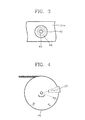
- Figure 4 is a view showing the rotary plate of Figure 2 on which paper size indicators are displayed.
-
- Referring to Figure 2, in a
paper tray 30, one or more control members such asfirst control plate 41 capable of linear movement to divide a paper storing space in a first direction, andsecond control plates - The
first control plate 41 engages with a multitude ofguide notches 44 in a row on the bottom surface of thepaper tray 30. Also, thesecond control plates paper tray 30. The distance betweenadjacent guide notches 44 is the minimum movement distance of thefirst control plate 41. Awindow 33 of a predetermined size for showing the inside of thepaper tray 30 is provided on one side of thefront side 32 of thepaper tray 30 having ahandle grip 31 for ejecting thepaper tray 30. Thewindow 33 may be a hole or formed of a transparent material. - Rotatable means comprising
pulley wheel 46 capable of rotating around arotary shaft 45 protruding from an inner wall 34a of agroove 34 of thepaper tray 30 is provided inside thepaper tray 30 behind thewindow 33. - As a linear/rotating movement converting means for rotating the
pulley wheel 46 with the linear movement of thefirst control plate 41, there are provided awire 47 having one end connected to one side of thepulley wheel 46 and the other end connected to the side of thefirst control plate 41 which faces away from the paper, and aroll spring 48 having its ends connected between thepulley wheel 46 and therotary shaft 45 on the inner wall 34a, for supplying restoring force with respect to the rotation of thepulley wheel 46 to a predetermined rotation position as shown in Figure 3, to maintain tension in thewire 47 regardless of the position of thefirst control plate 41. - The
roll spring 48 may be replaced by other resilient biasing means such as a rubber band. - The restoring force of the
roll spring 48 must only tension thewire 47, without moving thefirst control plate 41. - A
roller 49 allows the wire to slide easily. - According to the display of paper size, when paper size indicators corresponding to the distance between a
rear wall 35 of thepaper tray 30 and thefirst control plate 41 are arranged on a region of thepulley wheel 46 facing thewindow 33 as shown in Figure 4, a user can see paper size indicator which corresponds to the size of paper in thepaper tray 30 by control of thefirst control plate 41. - The
pulley wheel 46 and thewindow 33 facing thereto may be positioned considering the appearance of the printer and position of thepaper tray 30. - Meanwhile, the display of the paper size can be based on relative movement between the
second control plates pulley wheel 46, as well as relative movement between thefirst control plate 41 and thepulley wheel 46. - As described above, according to the display of the size of paper stored in the paper tray for the printer the size of the paper stored in the paper tray can be seen from the outside, so that the paper tray need not be opened to check the size of the stored paper.
wherein the roll spring is obtained by rolling a strip; and
wherein the rotatable means comprises a pulley wheel around which said wire is arranged to be wound or unwound according to the movement of the control member.
Claims (4)
- Apparatus for enabling the size of paper stored internally in a paper tray (30) loaded in a printer to be viewed from the exterior, the apparatus comprising:wherein a portion of the rotatable means (46) is arranged to be visible through a window (33) of said printer, and paper size indicators are displayed in radially-divided regions of the rotatable means (46) to show the paper size according to the position of the control member (41), characterised in that:at least one control member (41) capable of sliding linearly in a predetermined direction, installed in the paper tray (30) to define the edges of the stored paper;rotatable means (46) mounted for rotation about a point (45); andmeans for converting linear movement of the control member (41) into corresponding rotary movement of the rotatable means (46),
the linear/rotary movement converting means includes a wire (47) for connecting the rotatable means (46) to the control member (41) along a predetermined path, and biasing means (48) is provided for supplying restoring force to maintain tension in the wire (47) with respect to the linear movement of the control member (41),
wherein said biasing means (48) comprises a roll spring for supplying restoring force in a winding direction of said rotatable means (46),
wherein the roll spring is obtained by rolling a strip; and
wherein the rotatable means (46) comprises a pulley wheel around which said wire (47) is arranged to be wound or unwound according to the movement of the control member (41). - The apparatus according to claim 1, wherein said rotatable means (46) is mounted on a side portion of the paper tray (30).
- A printer tray (30) incorporating the apparatus of any preceding claim.
- A printer incorporating the printer tray (30) according to claim 3 or incorporating the apparatus according to claim 1 or 2.
Applications Claiming Priority (2)
| Application Number | Priority Date | Filing Date | Title |
|---|---|---|---|
| KR9768325 | 1997-12-12 | ||
| KR1019970068325A KR100234297B1 (en) | 1997-12-12 | 1997-12-12 | Paper size displaying device of paper cassette for printer |
Publications (3)
| Publication Number | Publication Date |
|---|---|
| EP0923003A2 EP0923003A2 (en) | 1999-06-16 |
| EP0923003A3 EP0923003A3 (en) | 2000-07-12 |
| EP0923003B1 true EP0923003B1 (en) | 2003-07-23 |
Family
ID=19527203
Family Applications (1)
| Application Number | Title | Priority Date | Filing Date |
|---|---|---|---|
| EP98304627A Expired - Lifetime EP0923003B1 (en) | 1997-12-12 | 1998-06-11 | Display of size of paper stored in printer paper tray |
Country Status (5)
| Country | Link |
|---|---|
| EP (1) | EP0923003B1 (en) |
| JP (1) | JPH11199061A (en) |
| KR (1) | KR100234297B1 (en) |
| CN (1) | CN1119274C (en) |
| DE (1) | DE69816575T2 (en) |
Families Citing this family (3)
| Publication number | Priority date | Publication date | Assignee | Title |
|---|---|---|---|---|
| JP5398757B2 (en) * | 2011-02-14 | 2014-01-29 | 京セラドキュメントソリューションズ株式会社 | Paper feeding device and image forming apparatus using the same |
| US9274480B1 (en) * | 2014-10-02 | 2016-03-01 | Xerox Corporation | Paper tray size sensing mechanism |
| US9561920B1 (en) | 2015-10-01 | 2017-02-07 | Xerox Corporation | Media supply tray having multi-color exterior light indicating different media loading conditions |
Family Cites Families (4)
| Publication number | Priority date | Publication date | Assignee | Title |
|---|---|---|---|---|
| JPS6061426A (en) * | 1983-09-10 | 1985-04-09 | Ricoh Co Ltd | Paper-sheet size detecting apparatus for copying machine |
| US4697803A (en) * | 1984-05-15 | 1987-10-06 | Sanyo Electric Co., Ltd. | Sheet member feeding cassette |
| JP2896299B2 (en) * | 1993-11-22 | 1999-05-31 | 株式会社リコー | Paper feeder |
| JPH08157077A (en) * | 1994-12-08 | 1996-06-18 | Canon Inc | Paper feed cassette and image forming apparatus |
-
1997
- 1997-12-12 KR KR1019970068325A patent/KR100234297B1/en not_active Expired - Fee Related
-
1998
- 1998-06-03 JP JP10154995A patent/JPH11199061A/en active Pending
- 1998-06-11 EP EP98304627A patent/EP0923003B1/en not_active Expired - Lifetime
- 1998-06-11 DE DE69816575T patent/DE69816575T2/en not_active Expired - Lifetime
- 1998-06-12 CN CN98114808A patent/CN1119274C/en not_active Expired - Fee Related
Also Published As
| Publication number | Publication date |
|---|---|
| JPH11199061A (en) | 1999-07-27 |
| KR19990049386A (en) | 1999-07-05 |
| DE69816575D1 (en) | 2003-08-28 |
| DE69816575T2 (en) | 2004-02-12 |
| EP0923003A2 (en) | 1999-06-16 |
| CN1119274C (en) | 2003-08-27 |
| CN1219475A (en) | 1999-06-16 |
| KR100234297B1 (en) | 1999-12-15 |
| EP0923003A3 (en) | 2000-07-12 |
Similar Documents
| Publication | Publication Date | Title |
|---|---|---|
| JP5163771B2 (en) | Image recording device | |
| US7654518B2 (en) | Image forming apparatus and paper guide unit thereof | |
| EP0719652A2 (en) | Thermal ribbon cassette for thermal printing device | |
| JP2003246484A (en) | Belt transport device | |
| WO2020154142A1 (en) | Imaging system | |
| JP6296008B2 (en) | Paper cassette and image forming apparatus | |
| JP2024043483A (en) | Image reading device and image forming device | |
| EP0923003A2 (en) | Display of size of paper stored in printer paper tray | |
| US7753308B2 (en) | Mechanism for preventing a winding slack of a roll paper | |
| JP2008254842A (en) | Image forming apparatus | |
| JP2000302311A (en) | Paper ejection device | |
| JP3233862B2 (en) | Fixing structure of image sensor in image forming apparatus | |
| US6070988A (en) | Control panel for an image forming device | |
| JPS59172332A (en) | Universal paper supply container for copying machine | |
| JP3948564B2 (en) | Image forming apparatus | |
| US5905926A (en) | Positioning structure for brake force supplier for use in image forming apparatus | |
| JP3083615B2 (en) | Sheet recording device | |
| US20250267222A1 (en) | Image reading apparatus and image forming apparatus | |
| JP2025109294A (en) | Image forming device | |
| JP2947345B2 (en) | Printing device | |
| JP2019174495A (en) | Image forming apparatus | |
| JP2966163B2 (en) | Paper feeder | |
| JP2571307Y2 (en) | Box guidance device | |
| JP2025136067A (en) | cassette | |
| JP4618710B2 (en) | Image forming apparatus |
Legal Events
| Date | Code | Title | Description |
|---|---|---|---|
| PUAI | Public reference made under article 153(3) epc to a published international application that has entered the european phase |
Free format text: ORIGINAL CODE: 0009012 |
|
| 17P | Request for examination filed |
Effective date: 19980619 |
|
| AK | Designated contracting states |
Kind code of ref document: A2 Designated state(s): DE FR GB |
|
| AX | Request for extension of the european patent |
Free format text: AL;LT;LV;MK;RO;SI |
|
| PUAL | Search report despatched |
Free format text: ORIGINAL CODE: 0009013 |
|
| AK | Designated contracting states |
Kind code of ref document: A3 Designated state(s): AT BE CH CY DE DK ES FI FR GB GR IE IT LI LU MC NL PT SE |
|
| AX | Request for extension of the european patent |
Free format text: AL;LT;LV;MK;RO;SI |
|
| AKX | Designation fees paid |
Free format text: DE FR GB |
|
| 17Q | First examination report despatched |
Effective date: 20020115 |
|
| GRAH | Despatch of communication of intention to grant a patent |
Free format text: ORIGINAL CODE: EPIDOS IGRA |
|
| GRAH | Despatch of communication of intention to grant a patent |
Free format text: ORIGINAL CODE: EPIDOS IGRA |
|
| GRAA | (expected) grant |
Free format text: ORIGINAL CODE: 0009210 |
|
| AK | Designated contracting states |
Designated state(s): DE FR GB |
|
| REG | Reference to a national code |
Ref country code: GB Ref legal event code: FG4D |
|
| REF | Corresponds to: |
Ref document number: 69816575 Country of ref document: DE Date of ref document: 20030828 Kind code of ref document: P |
|
| ET | Fr: translation filed | ||
| PLBE | No opposition filed within time limit |
Free format text: ORIGINAL CODE: 0009261 |
|
| STAA | Information on the status of an ep patent application or granted ep patent |
Free format text: STATUS: NO OPPOSITION FILED WITHIN TIME LIMIT |
|
| 26N | No opposition filed |
Effective date: 20040426 |
|
| REG | Reference to a national code |
Ref country code: FR Ref legal event code: PLFP Year of fee payment: 18 |
|
| PGFP | Annual fee paid to national office [announced via postgrant information from national office to epo] |
Ref country code: DE Payment date: 20150521 Year of fee payment: 18 Ref country code: GB Payment date: 20150522 Year of fee payment: 18 |
|
| PGFP | Annual fee paid to national office [announced via postgrant information from national office to epo] |
Ref country code: FR Payment date: 20150521 Year of fee payment: 18 |
|
| REG | Reference to a national code |
Ref country code: DE Ref legal event code: R119 Ref document number: 69816575 Country of ref document: DE |
|
| GBPC | Gb: european patent ceased through non-payment of renewal fee |
Effective date: 20160611 |
|
| REG | Reference to a national code |
Ref country code: FR Ref legal event code: ST Effective date: 20170228 |
|
| PG25 | Lapsed in a contracting state [announced via postgrant information from national office to epo] |
Ref country code: DE Free format text: LAPSE BECAUSE OF NON-PAYMENT OF DUE FEES Effective date: 20170103 Ref country code: FR Free format text: LAPSE BECAUSE OF NON-PAYMENT OF DUE FEES Effective date: 20160630 |
|
| REG | Reference to a national code |
Ref country code: GB Ref legal event code: 732E Free format text: REGISTERED BETWEEN 20170406 AND 20170412 |
|
| PG25 | Lapsed in a contracting state [announced via postgrant information from national office to epo] |
Ref country code: GB Free format text: LAPSE BECAUSE OF NON-PAYMENT OF DUE FEES Effective date: 20160611 |
|
| REG | Reference to a national code |
Ref country code: FR Ref legal event code: TP Owner name: S-PRINTING SOLUTION CO., LTD., KR Effective date: 20170912 |