EP0922975B1 - Pare-poussière universel - Google Patents
Pare-poussière universel Download PDFInfo
- Publication number
- EP0922975B1 EP0922975B1 EP98309847A EP98309847A EP0922975B1 EP 0922975 B1 EP0922975 B1 EP 0922975B1 EP 98309847 A EP98309847 A EP 98309847A EP 98309847 A EP98309847 A EP 98309847A EP 0922975 B1 EP0922975 B1 EP 0922975B1
- Authority
- EP
- European Patent Office
- Prior art keywords
- dust cover
- coupling assembly
- adapter
- pivot pin
- pivot
- Prior art date
- Legal status (The legal status is an assumption and is not a legal conclusion. Google has not performed a legal analysis and makes no representation as to the accuracy of the status listed.)
- Expired - Lifetime
Links
Images


Classifications
-
- G—PHYSICS
- G02—OPTICS
- G02B—OPTICAL ELEMENTS, SYSTEMS OR APPARATUS
- G02B6/00—Light guides; Structural details of arrangements comprising light guides and other optical elements, e.g. couplings
- G02B6/24—Coupling light guides
- G02B6/36—Mechanical coupling means
- G02B6/38—Mechanical coupling means having fibre to fibre mating means
- G02B6/3807—Dismountable connectors, i.e. comprising plugs
- G02B6/381—Dismountable connectors, i.e. comprising plugs of the ferrule type, e.g. fibre ends embedded in ferrules, connecting a pair of fibres
- G02B6/3825—Dismountable connectors, i.e. comprising plugs of the ferrule type, e.g. fibre ends embedded in ferrules, connecting a pair of fibres with an intermediate part, e.g. adapter, receptacle, linking two plugs
-
- G—PHYSICS
- G02—OPTICS
- G02B—OPTICAL ELEMENTS, SYSTEMS OR APPARATUS
- G02B6/00—Light guides; Structural details of arrangements comprising light guides and other optical elements, e.g. couplings
- G02B6/24—Coupling light guides
- G02B6/36—Mechanical coupling means
- G02B6/38—Mechanical coupling means having fibre to fibre mating means
- G02B6/3807—Dismountable connectors, i.e. comprising plugs
- G02B6/3833—Details of mounting fibres in ferrules; Assembly methods; Manufacture
- G02B6/3847—Details of mounting fibres in ferrules; Assembly methods; Manufacture with means preventing fibre end damage, e.g. recessed fibre surfaces
- G02B6/3849—Details of mounting fibres in ferrules; Assembly methods; Manufacture with means preventing fibre end damage, e.g. recessed fibre surfaces using mechanical protective elements, e.g. caps, hoods, sealing membranes
-
- H—ELECTRICITY
- H01—ELECTRIC ELEMENTS
- H01R—ELECTRICALLY-CONDUCTIVE CONNECTIONS; STRUCTURAL ASSOCIATIONS OF A PLURALITY OF MUTUALLY-INSULATED ELECTRICAL CONNECTING ELEMENTS; COUPLING DEVICES; CURRENT COLLECTORS
- H01R13/00—Details of coupling devices of the kinds covered by groups H01R12/70 or H01R24/00 - H01R33/00
- H01R13/46—Bases; Cases
- H01R13/52—Dustproof, splashproof, drip-proof, waterproof, or flameproof cases
- H01R13/5213—Covers
Definitions
- This invention relates to lightguide connector adapters for use in interconnecting optical fibers and, more particularly, to an adapter and a dust cover or shutter for blocking light energy within the connection and for preventing contaminants from entering vacant adapter apertures.
- Optical fiber transmission systems are becoming widely used in the transmission of signals such as data, voice and the like and, in many instances, are replacing traditional electrical systems.
- Many of the arrangements common to electrical systems, such as coupling, interconnection, splicing, and the like have their counterparts in optical systems but, because of the totally different characteristics of the transmission media, i.e., optical fiber versus metallic wire, connectorization, splicing, and the like involve quite a different apparatus.
- both systems may use what is referred to in the art as patch panels, which provide arrays of connector adapters for interconnection, but the interconnections themselves are generally quite different.
- an SC connector includes a ferrule assembly including a barrel having a collar at one end and an optical fiber terminating ferrule projecting from the barrel.
- the ferrule assembly is disposed in a plug frame such that an end portion of the ferrule projects from one end of the frame.
- the plug frame is configured to snap lock into a grip member having a locating key thereon, and the grip is inserted into one side of a slotted coupler adapter, with the locating key inserted into the slot.
- the grip of a corresponding SC connector is inserted into the other side of the adapter so that the ends of the ferrules abut each other to form a low insertion loss optical interconnection.
- the ferrules are spring loaded longitudinally to insure contact between the fiber containing ferrule ends.
- the entire interconnect operation involves linear motion only and results in a low insertion loss, mechanically stable, protected junction between two fibers.
- the expenditure of time in making the interconnection is small and the operator or installer is relieved of having to perform anything other than simple linear motion in plugging the connectors into the coupling adapter.
- Patent 5,274,729 of King et al. there is shown a buildout coupling adapter system in a patch panel that makes possible interconnections among the several different types of connectors in any combination thereof.
- a buildout block at one side (or end) thereof is configured the same as a simple coupler adapter having a keyway for receiving, for example, an SC connector.
- the other end of the buildout block is formed to receive a buildout which may be configured to receive and hold, for example, an SC, an ST, or an FC connector.
- the patch panel may be, on one side thereof, pre-connectorized with optical fibers all of which are terminated by SC connectors, and the other side of the panel is ready to receive pre-connectorized fibers terminated by any one of the numerous connectors.
- Such an arrangement is more versatile and adaptable than those arrangements which are limited to a single type of pre-connectorized fiber.
- Such an arrangement also functions well in those installations where one side of the panel is not readily accessible.
- the panel can be pre-connectorized before mounting in position on the side which will be relatively inaccessible, after which it can be mounted in place, ready to receive the numerous connections thereto, regardless of connector type.
- any such arrangement there is always the possibility of airborne contaminants or dust entering vacant apertures in the adapter as well as a potential safety hazard.
- one or more of the pre-connectorized fibers is carrying optical energy
- optical energy can be emitted from the end of the fiber connector and pass through the buildout block or coupling adapter to the side of the panel where connections are to be made.
- This optical energy can be harmful for the operator or installer and can be especially harmful to his or her eyes.
- This hazard is most prevalent when an active connection has to be repaired or otherwise altered by removing an existing connectorized fiber and replacing it with another. In such an instance, it might be difficult or otherwise impractical to shut off the signal transmission in that particular fiber circuit, hence, the installer is forced to deal with a light emitting junction or connection.
- This hazard has been recognized and there have been efforts made, in the prior art, to provide a dust cover for the opening in the buildout block or adapter to block at least some of the light emanating from a fiber connection through the open adapter.
- One such arrangement comprises a door like member pivotally mounted to the end of the adapter, with a biasing spring adapted to maintain the door in its closed position, blocking the open end of the adapter.
- EP 570652 A discloses a dust cover mounted on a specially designed connector plug. When the connector plug is inserted into the specially designed adapter, the dust cover on the connector plug is opened up, to permit light to pass therethrough. However, if the outer half of the adapter is empty, the light passes therethrough into the ambient surroundings.
- the dust cover taught by this document is affixed to the end of the connector plug and simply performs the function of the protection of the fiber end from foreign matter when the connector plug is not in use.
- the invention disclosed in that application is an optical shutter or dust cover for use with optical fiber coupling adapters which has a front, transverse face which is sufficient to cover the opening in the adapter.
- the transverse portion has a pair of pivot arms extending from either side thereof which are adapted, at their distal ends, to be pivotally connected to the coupling adapter, thereby providing a pivotal mounting for the shutter.
- the transverse face also has a flange extending from one end thereof to permit actuation of the shutter, i.e., opening or closing by means of the connector to be inserted in the adapter or after its removal from the adapter.
- the shutter is gravity operated, and provides the desired degree of protection; however, it depends upon gravity and friction for proper operation, and, where the adapter is mounted vertically in the patch panel, the gravity actuation is nullified and the shutter may be accidentally opened or moved from the closed position.
- the present invention overcomes most of the problems and disadvantages of the prior art, as discussed in the foregoing, and comprises an adapter and shutter assembly for use with, for example, a patch panel or other apparatus for retaining or containing adapters.
- the dust cover of the invention comprises an L-shaped member having a top surface and a front surface which is large enough to block the connector receptacle. Extending from the top surface at an angle thereto are first and second spaced pivot arms. Centrally located between the pivot arms and extending from the top surface also at an angle thereto is a spring arm having a distal end which has a slightly curved section adjacent the end.
- the L-shaped dust cover, the pivot arms, and the spring arm are preferably molded in one piece and are made of a suitable plastic material which is relatively hard and durable and fatigue resistant so that it does not lose its characteristics under use, i.e., as will be apparent hereinafter, the spring characteristics.
- Each of the pivot arms has a distal end forming an interior face, and each face has a detent recess therein.
- the adapter comprises a base and a cap member.
- the cap member has one or more apertures thereon for receiving fiber optic connectors, each cap being adapted to receive a particular type of connector, such as an SC, ST, or an LC connector.
- an arm extends from the rear of the cap toward the front thereof over the top surface, and spaced therefrom.
- a pivot pin which extends transversely to the opening or openings in the cap and is also parallel to the top surface and spaced therefrom. The two ends of each of the pivot pins are adapted to fit into the detent recesses in the pivot arm faces of the dust cover member whereby it is pivotable with respect to the cap member.
- Each of the pivot pins has a projecting cam located approximately midway between the two ends, upon which the curved distal end of the spring arm is adapted to bear when the pivot arms of the dust cover member are mounted to the pivot pin. The resilience of the arms is sufficient to maintain them in contact with the ends of the pivot pin.
- the dust cover member when mounted to the cap so that the ends of the pivot pins ride within the detent recesses, and the distal end of the spring arm rests on top of the cam, is held in position by the action of the spring arm against the cam.
- the dust cover member when mounted so that its front portion blocks the aperture in the cap, dust or other contaminants cannot enter the aperture, light carried by a fiber optic connector mounted in the base is at least partially blocked and accidental or gravity movement of the dust cover is prevented.
- the connector when it is desired to insert a connector into the aperture, the connector is made to bear against the bottom surface of a transverse flange on the bottom edge of the front face of the dust cover and lifted, thereby pivoting the dust cover to an open position allowing the connector to be inserted in the opening or aperture in the cap.
- This process is similar to that shown in the aforementioned patent No. 5,687,268 of Stephenson et al. In practice, the light signals are essentially blocked.
- the dust cover member has three basic positions; closed, open to allow a connector to be inserted into the aperture, and fully open. In the closed and fully open positions, the spring arm and cam action hold the dust cover in its position against accidental or gravity actuated movement.
- the arrangement of the present invention guarantees that the dust cover, regardless of the orientation of the adapter, e.g ., vertical or horizontal, will stay in its position until a positive, deliberately applied, force moves it.
- the dust cover member may be removed from the cap and stored until needed, thus, in the assembly of the patch panel, or in the mounting of the adapter thereto, it will not interfere with the installation.
- the dust cover member is universal, in that it fits readily on to an SC, ST, LC, or other type cap, thereby avoiding special adaptation to accommodate different types of connectors.
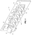
- Fig. 1 is a perspective, composite view of the adapter cap and shutter assembly incorporating the principles and features of the present invention, and illustrating the three basic positions of the shutter.
- the assembly 11 of Fig. 1 comprises a patch panel 12 to which is mounted an adapter 13, only the cap 14 of which is visible.
- cap 14 accommodates the ST type of optical fiber connector.
- Depicted in Fig. 1 is a ganged ST connector cap 14 having a plurality of receptacles 16 for receiving ST connectors. It is to be understood, however, that the principles of the invention apply to individual adapters, or to build-out blocks as discussed in the aforementioned Stephenson et al. application.
- a cantilevered arm 17 Extending from the rear of the cap 14 toward the front thereof and aligned with each receptacle 16 is a cantilevered arm 17 having a distal end 18 which has a transverse pivot pin 19 having slightly rounded ends 21.
- the cantilevered arm 17 and pivot pin 19 are spaced from the upper planar surface 22 of the cap 14, as can best be seen in Fig. 2b.
- the configuration of the arm 17 can best be seen in Figs. 2a and 2b which depict an adapter cap 23 configured for use with SC type couplers, Fig. 2a depicting the rear of cap 23 and Fig. 2b depicting, in cross-section, the side of cap 23.
- Figs. 2a and 2b depict an adapter cap 23 configured for use with SC type couplers
- the cantilevered arm 17 is preferably formed integrally with the cap member 23, both comprising a suitable plastic material such as polyetherimide or polysulfone, which are resistant to fatigue, and, being resilient or “springy” when cantilevered, as is arm 17, able to maintain that resilience despite considerable use.
- Arm 17 has a U- shaped configuration, as shown in Fig. 2a, and extends to the rear of the cap and then forward parallel to and spaced from the upper surface 26 of cap 23.
- a cam member 27 Located midway between the ends 21 of each of the pivot pins 19 is a cam member 27, the profile of which is best seen in Fig. 2b. Also as best seen in Fig.
- arm 17 has a slot 28 immediately behind pin 19, the purpose of which will be discussed more fully hereinafter.
- Each arm 17 has, on the top surface thereof, a wedge shaped protrusion 29 which is adapted to snap into corresponding slots in the adapter base member, as will be discussed hereinafter.
- the caps 14 and 23 are symmetrical, as seen in Figs. 2a and 2b, and can be inserted into the base member of the adapter without the necessity of determining which is the top and which is the bottom.
- Fig. 1 illustrates the three basic positions of a dust cover 31 in accordance with the present invention.
- Shutter 31 as will be more apparent hereinafter, has a first, closed position A; a second, partially open position B which is the position when an optical fiber connector, not shown, is inserted in one of the receptacles 16; and a third, fully open position C when access to the receptacle 16 is desired for cleaning, for example.
- the shutter is firmly held in each of the three positions A, B, and C.
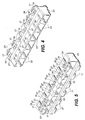
- Fig. 3 is a perspective view of the adapter 13 for use with SC type couplers.
- Adapter 13 comprises the cap member 23 shown in Figs. 2a and 2b and a base member 32 which are held together, by means of protrusions 29 being snapped into slots (not shown) in base member 32.
- Cap 23 has a plurality of rectangular openings 33 for receiving SC connectors, and key slots 34 for orienting the connectors in the openings 33.
- Base member 32 likewise has a plurality of openings 36 for receiving connectors, which may be any of a number of different types. Openings 36 may be pre-connectorized as discussed in the several prior art references.
- a gang type adapter having six openings is shown, it is to be understood that the adapter may comprise any practical number of openings, including just one, depending upon how many optical fiber connections are to be made.
- Figs. 4 and 5 are front and rear perspective views, respectively of cap member 23.
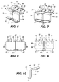
- Figs. 6 through 10 are various views of the dust cover member 31 which is adapted to be pivotably mounted on pivot pin 19 on cap member 14.
- member 31 has a substantially L-shaped profile having an upper leg 27, which has a planar top surface 38, and a depending leg 39 which is large enough to block the connector aperture in the cap.
- a transverse flange 41 which functions as an actuating member for pivotably raising or lowering the dust cover 31 in the manner taught in the aforementioned U.S. patent No. 5,687,268.
- the dust covers 31 are depicted as being paired, being joined together by webs 42 and 43.
- the dust covers 31, which are made of suitable plastic material such as polyetherimide or polysulfone in this manner.
- suitable plastic material such as polyetherimide or polysulfone
- first and second pivot arms 44 and 46 Extending from the top surface 38 of each dust cover 31 at an angle thereto are first and second pivot arms 44 and 46 which are spaced apart as shown.
- the distal ends 47 of the arms 44 and 46 are enlarged to form interior faces, each of which has a detent recess 48 therein for receiving the rounded ends 21 of the pivot pin 19.
- a channel 49 leads into each detent recess 48 to facilitate insertion of the ends 21 of the pin 19 into the recesses 48, which, when accomplished forms a pivot mounting arrangement for the dust cover 31.
- the plastic material of which the dust cover and the pivot arms are made has a degree of resilience which, in effect, enables the pivot arms 44 and 46 to snap over the ends 21 of the pivot pin 19 and to grip the pivot pin while still being pivotable with respect thereto.
- the material specified in the foregoing, or other suitable material provides the desired degree of resilience while still being resistant to fatigue.
- each pair of pivot arms 44 and 46 Approximately centrally located between each pair of pivot arms 44 and 46 is a spring arm 51 which extends from surface 38 at an angle thereto which approximates the angle of arms 44 and 46, as best seen in Figs. 6 and 7.
- the distal end 52 of each arm is slightly curved or flattened, as shown, the underside portion of the end 52 being adapted to bear against the cam member 27 on the adapter cap 14 or 23.
- the normal resilience of the spring arm 51 is sufficient to maintain it in contact with the camming surface of cam member 27 when the dust cover 31 is mounted in place on the pivot pin 19, regardless of the pivot position.
- the action of the spring arm 51 and the cam member 27 will be more readily understood by reference to Figs. 11, 12, and 13.
- Fig. 11 depicts, in partial cross-section, the dust cover 31 in its closed position (position A) over a vacant SC connector receptacle 16 such as shown in Fig. 2(b), which, as discussed in connection with the figure, comprises adapter cap member 23 and base 32. It can be seen in Fig. 11 that the underside of the curved or flattened portion 52 of spring arm 51 bears against the camming surface of cam member 27, and the resilience or “springiness" of the arm 51 maintains the dust cover 31 in its closed position.
- Fig. 12 depicts the dust cover 31 in its intermediate position (position B), with an SC connector 59 in receptacle 16.
- the flattened or curved end 52 of spring arm 51 is pressing approximately on the offset high point of the cam lobe so that there is a force exerted to press toward the closed position of the dust cover 31, and it remains in position B as long as connector 53 is in place.
- position B is reached by the installer using the connector 53 to bear against the underside of flange 41 to pivot the dust cover 31 from position A to position B.
- Fig. 13 depicts the fully open position (position C) of dust cover 31.
- an ST type connector 54 is shown in place for illustrative purposes only.
- Position C is most often used when receptacle 16 is vacant, and provides access to the interior of the receptacle 16 for cleaning or for making measurements or tests, for example.
- the end 52 of spring arm 51 has been moved past the high point of cam member 27, with end 52 penetrating into slot 28. With the end 52 of spring arm 51 in the position shown, dust cover 31 will remain open despite gravity or other extraneous force, requiring a positively applied force to move it from position C.
- the spring action of arm 51 against cam 27 prevents any accidental dislodgment from position C.
- the dust cover of the invention achieves the desired improvements over the prior art arrangements. More particularly, the dust cover is universal, i . e ., its configuration is such that it may be used with several different types of connectors and caps without modification.
- the adapter it is easy to mount to the adapter and has positive means for maintaining it in any of several positions, thereby avoiding accidental or undesired dislodgment. It affords both protection from contaminants for the adapter connections and at least some protection from light signals in the active receptacles prior to insertion of a connector therein. Numerous variations or modifications of the structure may occur to workers in the art without departure from the principles of the invention.
- spring arm 51 may comprise, for example, a metallic leaf spring, or pivot pin 19 may be affixed to the adapter cap in a manner other than that shown in the preferred embodiment. It is also possible, for example, that the pivot pin and cam might be located on the dust cover and the pivot arm and spring arm located on the adapter cap. All such variations or modifications are intended to be included within the scope of the present invention as set forth in the claims. Further, in the claims hereafter, the corresponding structures, materials, acts, and equivalents of all means or step plus function elements are intended to include any structure, material, or acts for performing the functions in combination with other claimed elements as specifically claimed.
Claims (13)
- Ensemble de couplage de guide de lumière (11) présentant un élément d'adaptateur de couplage (13) présentant un réceptacle recevant un connecteur (16), l'ensemble de couplage de guide de lumière comprenant :un couvercle pare-poussière (31) présentant une surface avant adaptée pour couvrir ledit réceptacle ;une goupille de pivotement (19) montée sur ledit adaptateur;un élément de came (27) sur ladite goupille de pivotement ;un premier (44) et un deuxième (46) bras pivotant distants l'un de l'autre sur ledit couvercle pare-poussière s'étendant vers ladite goupille de pivotement, chacun desdits bras pivotants présentant une extrémité distale (48) destinée à venir en prise de manière pivotante avec ladite goupille de pivotement ; etun bras à ressort (51) sur ledit couvercle pare-poussière s'étendant entre ledit couvercle pare-poussière et ledit élément de came, présentant une extrémité distale (52) s'appuyant contre ledit élément de came et déplaçable par rapport à ce dernier ;ladite goupille de pivotement s'étendant transversalement à travers une surface supérieure dudit élément d'adaptateur (13) et distant de cette dernière, ladite goupille de pivotement (19) présentant une première et une deuxième extrémité (21) avec lesquelles peuvent venir en prise de manière pivotante les extrémités distales (48) desdits bras pivotants.
- Ensemble de couplage (11) selon la revendication 1, dans lequel les première et deuxième extrémités de ladite goupille de pivotement (19) sont arrondies.
- Ensemble de couplage (11) selon la revendication 1, dans lequel ladite goupille de pivotement (19) est montée sur ledit adaptateur (13) au moyen d'un bras en porte-à-faux en forme de "U" (17).
- Ensemble de couplage (11) selon la revendication 1, dans lequel l'extrémité distale de chacun desdits premier et deuxième bras pivotants présente un évidement de détente (48) destiné à venir en prise avec une extrémité (21) de ladite goupille de pivotement (19).
- Ensemble de couplage (11) selon la revendication 1, dans lequel ledit élément de came (27) se situe sur ladite goupille de pivotement, entre lesdites première et deuxième extrémités (21) de cette dernière.
- Ensemble de couplage (11) selon la revendication 1, dans lequel ledit bras à ressort (51) se situe entre lesdits premier (44) et deuxième (46) bras pivotants.
- Ensemble de couplage (11) selon la revendication 6, dans lequel ledit bras à ressort (51) présente une extrémité distale (52) présentant une partie courbée destinée à venir en prise avec et à s'appuyer contre ledit élément de came (27).
- Ensemble de couplage (11) selon la revendication 1, dans lequel ledit couvercle pare-poussière (31), lesdits bras pivotants (44, 46) et ledit bras à ressort (51) sont réalisés en une matière plastique résiliente résistant à la fatigue.
- Ensemble de couplage (11) selon la revendication 8, dans lequel ladite matière plastique est un polyéthérimide.
- Ensemble de couplage (11) selon la revendication 8, dans lequel ladite matière plastique est un polysulfone.
- Ensemble de couplage (11) selon la revendication 1, dans lequel ledit couvercle pare-poussière (31) comprend un élément sensiblement en forme de "L" présentant une première partie transversale (39) et une deuxième partie transversale (27) s'étendant à partir de ladite première partie transversale (39), selon un angle par rapport à cette dernière, où lesdits premier (44) et deuxième (46) bras pivotants s'étendent à partir de ladite deuxième partie transversale (27), suivant un angle par rapport à cette dernière.
- Ensemble de couplage selon la revendication 11, dans lequel ledit bras à ressort (51) s'étend à partir de ladite deuxième partie transversale (27), suivant un angle par rapport à cette dernière.
- Ensemble de couplage selon la revendication 12, dans lequel ledit bras à ressort (51) se situe entre lesdits bras pivotants (44, 46).
Applications Claiming Priority (2)
| Application Number | Priority Date | Filing Date | Title |
|---|---|---|---|
| US988520 | 1997-12-10 | ||
| US08/988,520 US6041155A (en) | 1997-12-10 | 1997-12-10 | Universal dust cover |
Publications (3)
| Publication Number | Publication Date |
|---|---|
| EP0922975A2 EP0922975A2 (fr) | 1999-06-16 |
| EP0922975A3 EP0922975A3 (fr) | 2000-07-12 |
| EP0922975B1 true EP0922975B1 (fr) | 2006-04-12 |
Family
ID=25534215
Family Applications (1)
| Application Number | Title | Priority Date | Filing Date |
|---|---|---|---|
| EP98309847A Expired - Lifetime EP0922975B1 (fr) | 1997-12-10 | 1998-12-01 | Pare-poussière universel |
Country Status (4)
| Country | Link |
|---|---|
| US (1) | US6041155A (fr) |
| EP (1) | EP0922975B1 (fr) |
| JP (1) | JP3294208B2 (fr) |
| DE (1) | DE69834165T2 (fr) |
Families Citing this family (121)
| Publication number | Priority date | Publication date | Assignee | Title |
|---|---|---|---|---|
| US5883995A (en) | 1997-05-20 | 1999-03-16 | Adc Telecommunications, Inc. | Fiber connector and adapter |
| TW343739U (en) * | 1997-09-13 | 1998-10-21 | Transian Technology Co Ltd | An optic adapter with protection feature |
| EP1128199B8 (fr) * | 1998-07-27 | 2003-07-02 | Huber & Suhner Ag | Prise de connexion pour des guides d'ondes lumineuses |
| US6760531B1 (en) | 1999-03-01 | 2004-07-06 | Adc Telecommunications, Inc. | Optical fiber distribution frame with outside plant enclosure |
| US6217226B1 (en) * | 1999-03-18 | 2001-04-17 | Lucent Technologies, Inc. | Fiber optic coupling panel |
| US6524014B2 (en) * | 1999-04-01 | 2003-02-25 | Fitel Usa Corp. | Universal modular optical fiber buildout |
| EP1041413A1 (fr) * | 1999-04-01 | 2000-10-04 | Lucent Technologies Inc. | Base de fixation universelle encliquetable et système panneau de montage |
| US6283640B1 (en) * | 1999-04-01 | 2001-09-04 | Lucent Technologies Inc. | Tunable optical fiber buildout |
| US6254278B1 (en) * | 1999-10-06 | 2001-07-03 | Lucent Technologies Inc. | Optical fiber tunable connector adapter |
| JP2001201671A (ja) * | 2000-01-20 | 2001-07-27 | Hosiden Corp | 光コネクタ |
| US6315590B1 (en) * | 2000-04-03 | 2001-11-13 | Molex Incorporated | Floating panel mounted connector assembly |
| US6375363B1 (en) | 2000-06-02 | 2002-04-23 | Cisco Technology, Inc. | Multi-part optical safety clip |
| US6601995B1 (en) * | 2000-06-02 | 2003-08-05 | Cisco Technology, Inc | Optical connector with flexible shielding cover |
| US6412986B1 (en) * | 2000-06-30 | 2002-07-02 | Berg Technology, Inc. | Adapter for assembling multiple optical connectors |
| US6425694B1 (en) * | 2000-09-18 | 2002-07-30 | Molex Incorporated | Fiber optic receptacle with protective shutter |
| US6443627B1 (en) | 2001-01-10 | 2002-09-03 | Fitel Usa Corp. | Duplex optical connector |
| US6478472B1 (en) | 2001-01-10 | 2002-11-12 | Fitel Usa Corp. | High-density optical connecting block |
| US6595696B1 (en) * | 2001-03-14 | 2003-07-22 | Amphenol Corporation | Internal shutter for optical adapters |
| US6547450B2 (en) | 2001-06-27 | 2003-04-15 | Fitel Usa Corp. | Quick-release dust cap for an optical plug |
| FR2832226B1 (fr) * | 2001-11-13 | 2004-10-22 | Nexans | Module de distribution et de connexion de fibres optiques destine a un repartiteur optique |
| TW493760U (en) * | 2001-11-30 | 2002-07-01 | Hon Hai Prec Ind Co Ltd | Optical fiber connector |
| WO2003096092A1 (fr) * | 2002-05-14 | 2003-11-20 | Huber+Suhner Ag | Connecteur optique |
| US7142764B2 (en) | 2003-03-20 | 2006-11-28 | Tyco Electronics Corporation | Optical fiber interconnect cabinets, termination modules and fiber connectivity management for the same |
| US7198409B2 (en) | 2003-06-30 | 2007-04-03 | Adc Telecommunications, Inc. | Fiber optic connector holder and method |
| US7233731B2 (en) * | 2003-07-02 | 2007-06-19 | Adc Telecommunications, Inc. | Telecommunications connection cabinet |
| US6986607B2 (en) | 2003-09-26 | 2006-01-17 | Roth Richard F | Protective covers for fiber optic connector to modular protective covers for fiber optic connector assembly |
| US6983095B2 (en) * | 2003-11-17 | 2006-01-03 | Fiber Optic Network Solutions Corporation | Systems and methods for managing optical fibers and components within an enclosure in an optical communications network |
| US7369741B2 (en) * | 2003-11-17 | 2008-05-06 | Fiber Optics Network Solutions Corp. | Storage adapter with dust cap posts |
| US7164840B2 (en) | 2004-03-30 | 2007-01-16 | Finisar Corporation | Dust cap for fiber optic components |
| US7218827B2 (en) * | 2004-06-18 | 2007-05-15 | Adc Telecommunications, Inc. | Multi-position fiber optic connector holder and method |
| US7194181B2 (en) | 2005-03-31 | 2007-03-20 | Adc Telecommunications, Inc. | Adapter block including connector storage |
| US7760984B2 (en) | 2006-05-04 | 2010-07-20 | Adc Telecommunications, Inc. | Fiber distribution hub with swing frame and wrap-around doors |
| EP1972974A1 (fr) * | 2007-03-20 | 2008-09-24 | Ridgemount Technologies Limited | Assemblée d'obturateur de fibre optique |
| JP4986289B2 (ja) * | 2007-07-04 | 2012-07-25 | 株式会社正電社 | 光コネクタ防塵用シャッター装置及びそれに用いるコネクタアダプタ |
| JP4841514B2 (ja) * | 2007-07-25 | 2011-12-21 | 株式会社正電社 | 光コネクタ防塵用シャッター装置及びそれに用いるコネクタアダプタ |
| US8229265B2 (en) * | 2007-11-21 | 2012-07-24 | Adc Telecommunications, Inc. | Fiber distribution hub with multiple configurations |
| JP5015812B2 (ja) * | 2008-01-31 | 2012-08-29 | スリーエム イノベイティブ プロパティズ カンパニー | コネクタ用カバー |
| CN103543501B (zh) | 2008-08-27 | 2016-08-24 | Adc电信公司 | 具有整体成型的箍圈对准结构的光纤适配器 |
| US8417074B2 (en) | 2008-11-21 | 2013-04-09 | Adc Telecommunications, Inc. | Fiber optic telecommunications module |
| AU2009201426B2 (en) * | 2009-04-13 | 2013-11-07 | Gravolin, Dennis Ronald Mr | Protective Housing Assembly |
| US8408815B2 (en) * | 2009-06-18 | 2013-04-02 | Senko Advanced Components, Inc. | Optical fiber connector and adapter |
| CN102116909B (zh) * | 2010-01-04 | 2012-09-05 | 泰科电子(上海)有限公司 | 用于光纤适配器接口的安全装置 |
| EP2542930A1 (fr) | 2010-03-02 | 2013-01-09 | Tyco Electronics Services GmbH | Module de télécommunication à fibre optique |
| CN102565957B (zh) * | 2010-12-31 | 2014-03-26 | 深圳日海通讯技术股份有限公司 | 一种光纤连接器 |
| US9188747B2 (en) | 2011-05-23 | 2015-11-17 | Senko Advanced Components, Inc. | True one piece housing fiber optic adapter |
| US9417418B2 (en) | 2011-09-12 | 2016-08-16 | Commscope Technologies Llc | Flexible lensed optical interconnect device for signal distribution |
| US8465317B2 (en) * | 2011-10-05 | 2013-06-18 | Senko Advanced Components, Inc. | Latching connector with remote release |
| CN103917904A (zh) | 2011-10-07 | 2014-07-09 | Adc电信公司 | 光纤盒、系统和方法 |
| WO2013112451A1 (fr) * | 2012-01-27 | 2013-08-01 | Commscope, Inc. Of North Carolina | Module à fibres optiques doté d'un bloc de montage pour fixer un connecteur de fibres optiques |
| US8974124B2 (en) | 2012-08-16 | 2015-03-10 | Senko Advanced Components, Inc. | Fiber optic connector |
| US9146362B2 (en) | 2012-09-21 | 2015-09-29 | Adc Telecommunications, Inc. | Insertion and removal tool for a fiber optic ferrule alignment sleeve |
| US9146374B2 (en) | 2012-09-28 | 2015-09-29 | Adc Telecommunications, Inc. | Rapid deployment packaging for optical fiber |
| US9488788B2 (en) | 2012-09-28 | 2016-11-08 | Commscope Technologies Llc | Fiber optic cassette |
| US9223094B2 (en) | 2012-10-05 | 2015-12-29 | Tyco Electronics Nederland Bv | Flexible optical circuit, cassettes, and methods |
| US9435975B2 (en) | 2013-03-15 | 2016-09-06 | Commscope Technologies Llc | Modular high density telecommunications frame and chassis system |
| US9268103B2 (en) | 2013-05-10 | 2016-02-23 | Senko Advanced Components, Inc. | Interlockable fiber optic connector adaptors |
| US9360649B2 (en) | 2013-05-22 | 2016-06-07 | Senko Advanced Components, Inc. | Cable guide for fiber optic cables |
| US9337593B2 (en) * | 2013-06-13 | 2016-05-10 | Intermountain Electronics, Inc. | Plug and receptacle assembly |
| US9618703B2 (en) | 2013-10-03 | 2017-04-11 | Senko Advanced Components, Inc. | Connector housing for securing an optical cable and methods of use and manufacture thereof |
| US9477049B2 (en) | 2013-12-20 | 2016-10-25 | Senko Advanced Components, Inc. | Lockable connectors and connection assemblies |
| US9851524B2 (en) | 2014-01-28 | 2017-12-26 | Commscope Technologies Llc | Slidable fiber optic connection module with cable slack management |
| US9535230B2 (en) | 2014-01-31 | 2017-01-03 | Senko Advanced Components, Inc. | Integrated fiber optic cable fan-out connector |
| US9494758B2 (en) | 2014-04-03 | 2016-11-15 | Commscope Technologies Llc | Fiber optic distribution system |
| US9297964B2 (en) | 2014-04-18 | 2016-03-29 | Senko Advanced Components, Inc. | Optical fiber connector assembly |
| US9274287B2 (en) | 2014-05-13 | 2016-03-01 | Senko Advanced Components, Inc. | Optical fiber connector and ferrule |
| US9618702B2 (en) | 2014-06-09 | 2017-04-11 | Senko Advanced Components, Inc. | Reduced-profile data transmission element connectors, adapters, and connection assemblies thereof |
| TWI553972B (zh) * | 2014-08-28 | 2016-10-11 | 緯創資通股份有限公司 | 防塵裝置 |
| US9599778B2 (en) | 2014-10-22 | 2017-03-21 | Senko Advanced Components, Inc. | Latching connector with remote release |
| US9494745B2 (en) | 2015-01-16 | 2016-11-15 | Senko Advanced Components, Inc. | Sealable communication cable connection assemblies |
| US9658409B2 (en) | 2015-03-03 | 2017-05-23 | Senko Advanced Components, Inc. | Optical fiber connector with changeable polarity |
| US10302874B2 (en) | 2015-05-15 | 2019-05-28 | Commscope Telecommunications (Shanghai) Co., Ltd. | Alignment sleeve assembly and fiber optic adapter |
| US9684139B2 (en) | 2015-05-29 | 2017-06-20 | Senko Advanced Components, Inc. | Optical fiber connector with changeable gender |
| US9726830B1 (en) | 2016-06-28 | 2017-08-08 | Senko Advanced Components, Inc. | Connector and adapter system for two-fiber mechanical transfer type ferrule |
| US10228521B2 (en) | 2016-12-05 | 2019-03-12 | Senko Advanced Components, Inc. | Narrow width adapters and connectors with modular latching arm |
| US10078188B1 (en) | 2016-12-05 | 2018-09-18 | Senko Advanced Components, Inc. | Springless push/pull fiber optic connector |
| US10185100B2 (en) | 2017-01-30 | 2019-01-22 | Senko Advanced Components, Inc | Modular connector and adapter assembly using a removable anchor device |
| US10444444B2 (en) | 2017-01-30 | 2019-10-15 | Senko Advanced Components, Inc. | Remote release tab connector assembly |
| US10416394B2 (en) | 2017-01-30 | 2019-09-17 | Senko Advanced Components, Inc. | Fiber optic receptacle with integrated device therein |
| US11333836B2 (en) | 2017-01-30 | 2022-05-17 | Senko Advanced Components, Inc. | Adapter for optical connectors |
| US10725248B2 (en) | 2017-01-30 | 2020-07-28 | Senko Advanced Components, Inc. | Fiber optic receptacle with integrated device therein incorporating a behind-the-wall fiber optic receptacle |
| WO2018140981A1 (fr) | 2017-01-30 | 2018-08-02 | Senko Advanced Components, Inc. | Connecteurs optiques à polarité réversible |
| US9989712B1 (en) | 2017-03-20 | 2018-06-05 | Senko Advanced Components, Inc | MPO connector assembly with push-pull tab |
| US10754098B2 (en) | 2017-04-07 | 2020-08-25 | Senko Advanced Components, Inc. | Behind the wall optical connector with reduced components |
| US10989884B2 (en) | 2017-04-07 | 2021-04-27 | Senko Advanced Components, Inc. | Behind the wall optical connector with reduced components |
| US10209461B2 (en) | 2017-04-07 | 2019-02-19 | Senko Advanced Components | Behind the wall optical connector with reduced components |
| US10359583B2 (en) | 2017-04-07 | 2019-07-23 | Senko Advanced Components, Inc. | Behind the wall optical connector with reduced components |
| US10718910B2 (en) | 2017-05-03 | 2020-07-21 | Senko Advanced Components, Inc | Field terminated ruggedized fiber optic connector system |
| US10401576B2 (en) | 2017-05-10 | 2019-09-03 | Senko Advanced Components, Inc. | MPO micro-latch-lock connector |
| US10146016B1 (en) | 2017-05-10 | 2018-12-04 | Senko Advanced Components, Inc | MPO micro-latchlock connector |
| US10295759B2 (en) | 2017-05-18 | 2019-05-21 | Senko Advanced Components, Inc. | Optical connector with forward-biasing projections |
| US10359576B2 (en) | 2017-06-15 | 2019-07-23 | Senko Advanced Components, Inc. | SC low profile connector with optional boot |
| US10718911B2 (en) | 2017-08-24 | 2020-07-21 | Senko Advanced Components, Inc. | Ultra-small form factor optical connectors using a push-pull boot receptacle release |
| US11822133B2 (en) | 2017-07-14 | 2023-11-21 | Senko Advanced Components, Inc. | Ultra-small form factor optical connector and adapter |
| US10281668B2 (en) | 2017-07-14 | 2019-05-07 | Senko Advanced Components, Inc. | Ultra-small form factor optical connectors |
| US10705300B2 (en) | 2017-07-14 | 2020-07-07 | Senko Advanced Components, Inc. | Small form factor fiber optic connector with multi-purpose boot assembly |
| US10641972B2 (en) | 2017-08-17 | 2020-05-05 | Senko Advanced Components, Inc | Anti-jam alignment sleeve holder or connector housing for a ferrule assembly |
| US11409068B2 (en) | 2017-10-02 | 2022-08-09 | Commscope Technologies Llc | Fiber optic circuit and preparation method |
| US10444442B2 (en) | 2017-11-03 | 2019-10-15 | Senko Advanced Components, Inc. | MPO optical fiber connector |
| US11002923B2 (en) | 2017-11-21 | 2021-05-11 | Senko Advanced Components, Inc. | Fiber optic connector with cable boot release having a two-piece clip assembly |
| US10678000B2 (en) | 2018-01-05 | 2020-06-09 | Senko Advanced Components, Inc. | Pull rod and alignment key for a fiber optic connector and adapter |
| WO2019183070A2 (fr) | 2018-03-19 | 2019-09-26 | Senko Advanced Components, Inc. | Outil de retrait permettant de retirer d'une interface d'adaptateur une pluralité de micro-connecteurs optiques |
| US11041993B2 (en) | 2018-04-19 | 2021-06-22 | Senko Advanced Components, Inc. | Fiber optic adapter with removable insert for polarity change and removal tool for the same |
| US10921528B2 (en) | 2018-06-07 | 2021-02-16 | Senko Advanced Components, Inc. | Dual spring multi-fiber optic connector |
| CN112088327A (zh) | 2018-07-15 | 2020-12-15 | 扇港元器件股份有限公司 | 超小型光学连接器和适配器 |
| US10444441B1 (en) | 2018-08-10 | 2019-10-15 | Senko Advanced Components, Inc. | Pivotable housing for a fiber optic connector |
| US11073664B2 (en) | 2018-08-13 | 2021-07-27 | Senko Advanced Components, Inc. | Cable boot assembly for releasing fiber optic connector from a receptacle |
| US10921531B2 (en) | 2018-09-12 | 2021-02-16 | Senko Advanced Components, Inc. | LC type connector with push/pull assembly for releasing connector from a receptacle using a cable boot |
| US10921530B2 (en) | 2018-09-12 | 2021-02-16 | Senko Advanced Components, Inc. | LC type connector with push/pull assembly for releasing connector from a receptacle using a cable boot |
| US11086087B2 (en) | 2018-09-12 | 2021-08-10 | Senko Advanced Components, Inc. | LC type connector with clip-on push/pull tab for releasing connector from a receptacle using a cable boot |
| US11806831B2 (en) | 2018-11-21 | 2023-11-07 | Senko Advanced Components, Inc. | Fixture and method for polishing fiber optic connector ferrules |
| US11175464B2 (en) | 2018-11-25 | 2021-11-16 | Senko Advanced Components, Inc. | Open ended spring body for use in an optical fiber connector |
| US11689247B2 (en) | 2019-01-16 | 2023-06-27 | Mertek Industries, Llc | Patch cord including wireless components |
| WO2020198755A1 (fr) | 2019-03-28 | 2020-10-01 | Senko Advanced Components, Inc | Ensemble adaptateur pour fibre optique |
| US11340406B2 (en) | 2019-04-19 | 2022-05-24 | Senko Advanced Components, Inc. | Small form factor fiber optic connector with resilient latching mechanism for securing within a hook-less receptacle |
| WO2020252355A1 (fr) | 2019-06-13 | 2020-12-17 | Senko Advanced Components, Inc | Bras de verrouillage actionné par levier pour libérer un connecteur de fibre optique d'un orifice de réceptacle et procédé d'utilisation |
| US11467354B2 (en) | 2019-07-23 | 2022-10-11 | Senko Advanced Components, Inc. | Ultra-small form factor receptacle for receiving a fiber optic connector opposing a ferrule assembly |
| US11353664B1 (en) | 2019-08-21 | 2022-06-07 | Senko Advanced Components, Inc. | Fiber optic connector |
| CN114787677A (zh) | 2019-11-13 | 2022-07-22 | 扇港元器件有限公司 | 光纤连接器 |
| TWI801777B (zh) * | 2020-07-07 | 2023-05-11 | 立佳興業股份有限公司 | 光學防塵器及其光學連接器模組 |
| US11539156B1 (en) * | 2021-06-23 | 2022-12-27 | Appleton Grp Llc | Flip cover assembly for an electrical plug-receptacle pair |
| CN115933076B (zh) * | 2023-02-24 | 2023-05-02 | 钇芯光子技术(深圳)有限公司 | 一种户外型光电模块 |
Family Cites Families (6)
| Publication number | Priority date | Publication date | Assignee | Title |
|---|---|---|---|---|
| US5030120A (en) * | 1990-07-02 | 1991-07-09 | Hughes Aircraft Company | Dust cover and locking assembly for electrical or fiber optic connector |
| DE4225689C1 (fr) * | 1992-08-04 | 1993-04-08 | Schoeller & Co Elektrotechnische Fabrik Gmbh & Co, 6000 Frankfurt, De | |
| US5414790A (en) * | 1993-11-09 | 1995-05-09 | Minnesota Mining And Manufacturing Company | Actuation tool and cap for fiber optic connector |
| US5506922A (en) * | 1994-08-01 | 1996-04-09 | Molex Incorporated | Fiber optic component assembly with a movable protective shield |
| US5687268A (en) * | 1995-11-27 | 1997-11-11 | Lucent Technologies Inc. | Pivotable optical shutter for blocking emission from a lightguide adapter #5 |
| AU719299B2 (en) * | 1996-08-08 | 2000-05-04 | Diamond S.A. | Plug portion for an optical fiber connector |
-
1997
- 1997-12-10 US US08/988,520 patent/US6041155A/en not_active Expired - Lifetime
-
1998
- 1998-12-01 EP EP98309847A patent/EP0922975B1/fr not_active Expired - Lifetime
- 1998-12-01 DE DE69834165T patent/DE69834165T2/de not_active Expired - Lifetime
- 1998-12-07 JP JP34739298A patent/JP3294208B2/ja not_active Expired - Fee Related
Also Published As
| Publication number | Publication date |
|---|---|
| JPH11250977A (ja) | 1999-09-17 |
| JP3294208B2 (ja) | 2002-06-24 |
| EP0922975A3 (fr) | 2000-07-12 |
| DE69834165D1 (de) | 2006-05-24 |
| DE69834165T2 (de) | 2006-08-31 |
| US6041155A (en) | 2000-03-21 |
| EP0922975A2 (fr) | 1999-06-16 |
Similar Documents
| Publication | Publication Date | Title |
|---|---|---|
| EP0922975B1 (fr) | Pare-poussière universel | |
| US5687268A (en) | Pivotable optical shutter for blocking emission from a lightguide adapter #5 | |
| US5757997A (en) | Optical fiber connector using fiber spring force alignment groove | |
| EP0949522B1 (fr) | Arrangement pour receptacle d'un connecteur à fibre optique | |
| US6108482A (en) | Fiber optic connector receptacle | |
| US6086263A (en) | Active device receptacle | |
| AU711594B2 (en) | Optical fiber connector using fiber spring force and alignment groove | |
| US5909526A (en) | Fiber optic connector assembly | |
| US5836031A (en) | Fiber optic cable cleaner | |
| US6464408B1 (en) | Fiber optic connectors | |
| US6471412B1 (en) | Fiber optic connector receptacle | |
| EP0788002A1 (fr) | Connecteur enfichable à fibre optique avec volet d'obturation | |
| US20090285541A1 (en) | Fiber optic connector holder | |
| EP0175788A1 (fr) | Appareil de connexion pour fibres optiques. | |
| KR20000048241A (ko) | 커넥터 조립체 | |
| RU2179733C2 (ru) | Розетка с электрооптическим устройством | |
| KR19990076635A (ko) | 섬유 스프링력과 정렬 홈을 이용한 광 섬유 커넥터 | |
| MXPA98004986A (en) | Receptacle for electro-opt device |
Legal Events
| Date | Code | Title | Description |
|---|---|---|---|
| PUAI | Public reference made under article 153(3) epc to a published international application that has entered the european phase |
Free format text: ORIGINAL CODE: 0009012 |
|
| AK | Designated contracting states |
Kind code of ref document: A2 Designated state(s): DE FR GB |
|
| AX | Request for extension of the european patent |
Free format text: AL;LT;LV;MK;RO;SI |
|
| PUAL | Search report despatched |
Free format text: ORIGINAL CODE: 0009013 |
|
| AK | Designated contracting states |
Kind code of ref document: A3 Designated state(s): AT BE CH CY DE DK ES FI FR GB GR IE IT LI LU MC NL PT SE |
|
| AX | Request for extension of the european patent |
Free format text: AL;LT;LV;MK;RO;SI |
|
| 17P | Request for examination filed |
Effective date: 20001214 |
|
| AKX | Designation fees paid |
Free format text: DE FR GB |
|
| 17Q | First examination report despatched |
Effective date: 20040311 |
|
| GRAP | Despatch of communication of intention to grant a patent |
Free format text: ORIGINAL CODE: EPIDOSNIGR1 |
|
| GRAS | Grant fee paid |
Free format text: ORIGINAL CODE: EPIDOSNIGR3 |
|
| GRAA | (expected) grant |
Free format text: ORIGINAL CODE: 0009210 |
|
| AK | Designated contracting states |
Kind code of ref document: B1 Designated state(s): DE FR GB |
|
| REG | Reference to a national code |
Ref country code: GB Ref legal event code: FG4D |
|
| REF | Corresponds to: |
Ref document number: 69834165 Country of ref document: DE Date of ref document: 20060524 Kind code of ref document: P |
|
| ET | Fr: translation filed | ||
| PLBE | No opposition filed within time limit |
Free format text: ORIGINAL CODE: 0009261 |
|
| STAA | Information on the status of an ep patent application or granted ep patent |
Free format text: STATUS: NO OPPOSITION FILED WITHIN TIME LIMIT |
|
| 26N | No opposition filed |
Effective date: 20070115 |
|
| PGFP | Annual fee paid to national office [announced via postgrant information from national office to epo] |
Ref country code: GB Payment date: 20121227 Year of fee payment: 15 |
|
| PGFP | Annual fee paid to national office [announced via postgrant information from national office to epo] |
Ref country code: FR Payment date: 20130110 Year of fee payment: 15 |
|
| PGFP | Annual fee paid to national office [announced via postgrant information from national office to epo] |
Ref country code: DE Payment date: 20121231 Year of fee payment: 15 |
|
| REG | Reference to a national code |
Ref country code: DE Ref legal event code: R119 Ref document number: 69834165 Country of ref document: DE |
|
| GBPC | Gb: european patent ceased through non-payment of renewal fee |
Effective date: 20131201 |
|
| REG | Reference to a national code |
Ref country code: FR Ref legal event code: ST Effective date: 20140829 |
|
| REG | Reference to a national code |
Ref country code: DE Ref legal event code: R119 Ref document number: 69834165 Country of ref document: DE Effective date: 20140701 |
|
| PG25 | Lapsed in a contracting state [announced via postgrant information from national office to epo] |
Ref country code: DE Free format text: LAPSE BECAUSE OF NON-PAYMENT OF DUE FEES Effective date: 20140701 |
|
| PG25 | Lapsed in a contracting state [announced via postgrant information from national office to epo] |
Ref country code: FR Free format text: LAPSE BECAUSE OF NON-PAYMENT OF DUE FEES Effective date: 20131231 Ref country code: GB Free format text: LAPSE BECAUSE OF NON-PAYMENT OF DUE FEES Effective date: 20131201 |