EP0922180B1 - Field joint - Google Patents
Field joint Download PDFInfo
- Publication number
- EP0922180B1 EP0922180B1 EP97930616A EP97930616A EP0922180B1 EP 0922180 B1 EP0922180 B1 EP 0922180B1 EP 97930616 A EP97930616 A EP 97930616A EP 97930616 A EP97930616 A EP 97930616A EP 0922180 B1 EP0922180 B1 EP 0922180B1
- Authority
- EP
- European Patent Office
- Prior art keywords
- field joint
- parent coating
- pipes
- polyurethane
- coating
- Prior art date
- Legal status (The legal status is an assumption and is not a legal conclusion. Google has not performed a legal analysis and makes no representation as to the accuracy of the status listed.)
- Expired - Lifetime
Links
Images

Classifications
-
- F—MECHANICAL ENGINEERING; LIGHTING; HEATING; WEAPONS; BLASTING
- F16—ENGINEERING ELEMENTS AND UNITS; GENERAL MEASURES FOR PRODUCING AND MAINTAINING EFFECTIVE FUNCTIONING OF MACHINES OR INSTALLATIONS; THERMAL INSULATION IN GENERAL
- F16L—PIPES; JOINTS OR FITTINGS FOR PIPES; SUPPORTS FOR PIPES, CABLES OR PROTECTIVE TUBING; MEANS FOR THERMAL INSULATION IN GENERAL
- F16L13/00—Non-disconnectable pipe joints, e.g. soldered, adhesive, or caulked joints
- F16L13/02—Welded joints
- F16L13/0254—Welded joints the pipes having an internal or external coating
- F16L13/0272—Welded joints the pipes having an internal or external coating having an external coating
-
- F—MECHANICAL ENGINEERING; LIGHTING; HEATING; WEAPONS; BLASTING
- F16—ENGINEERING ELEMENTS AND UNITS; GENERAL MEASURES FOR PRODUCING AND MAINTAINING EFFECTIVE FUNCTIONING OF MACHINES OR INSTALLATIONS; THERMAL INSULATION IN GENERAL
- F16L—PIPES; JOINTS OR FITTINGS FOR PIPES; SUPPORTS FOR PIPES, CABLES OR PROTECTIVE TUBING; MEANS FOR THERMAL INSULATION IN GENERAL
- F16L58/00—Protection of pipes or pipe fittings against corrosion or incrustation
- F16L58/18—Protection of pipes or pipe fittings against corrosion or incrustation specially adapted for pipe fittings
- F16L58/181—Protection of pipes or pipe fittings against corrosion or incrustation specially adapted for pipe fittings for non-disconnectable pipe joints
-
- F—MECHANICAL ENGINEERING; LIGHTING; HEATING; WEAPONS; BLASTING
- F16—ENGINEERING ELEMENTS AND UNITS; GENERAL MEASURES FOR PRODUCING AND MAINTAINING EFFECTIVE FUNCTIONING OF MACHINES OR INSTALLATIONS; THERMAL INSULATION IN GENERAL
- F16L—PIPES; JOINTS OR FITTINGS FOR PIPES; SUPPORTS FOR PIPES, CABLES OR PROTECTIVE TUBING; MEANS FOR THERMAL INSULATION IN GENERAL
- F16L59/00—Thermal insulation in general
- F16L59/14—Arrangements for the insulation of pipes or pipe systems
- F16L59/16—Arrangements specially adapted to local requirements at flanges, junctions, valves or the like
- F16L59/18—Arrangements specially adapted to local requirements at flanges, junctions, valves or the like adapted for joints
- F16L59/20—Arrangements specially adapted to local requirements at flanges, junctions, valves or the like adapted for joints for non-disconnectable joints
Definitions
- This invention relates to a method of forming a field joint for insulated pipelines for use especially, but not exclusively, sub-sea and, more specifically, to a method of forming a field joint for insulated pipelines which facilitates smooth reeling and laying of the pipelines.
- Pipes which are factory-coated with an elastomer or insulation coating can only be coated to within approximately 200 mm of the pipe ends as a section of the pipe end must be left bare to allow pipes to be joined together, normally by a welding process.
- the pipes are normally welded together as an integral part of the pipe laying process. Where this is carried out off shore the pipe welding would generally take place on a lay barge or a reel ship on a continuous basis.
- the insulation at the field joint should meet a similar specification as that of the parent coating but using the process used for applying the parent coating to the body of the pipe would increase the production time by an unacceptable amount.
- the presently used solution to the problem of filling the field joint within the time taken for the welding process is to apply a sheet metal mould around the parent coating of the pipe, inject a quick setting insulation material such as polyurethane or polyolefin, allow it to set and remove the mould.
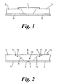
- Figure 1 of the drawings illustrates a typical field joint produced in accordance with this known method between two coated pipe sections A and B.
- the above method produces a satisfactory field joint C between the ends of two pipe sections, as the polyurethane filler overlaps the polypropylene coating D at the ends of the pipe, this reduces the reliability of the resulting pipeline.
- the coated pipe has to pass over a roller as it heads out-board of the lay barge or reeling ship and this often results in snagging of the field joint during both reeling and subsequent laying of the pipeline. This can damage both the field joint and also lead to damage to the rollers over a period of time due to the large number of field joints passing over the rollers during a pipe-line laying operation.
- EP-A-0360028 describes a method of forming a field joint around the bare joint of two joined insulation covered pipes.
- the outer coating and the parent coating on the pipe are prepared by providing a first cut back followed by a second angular cut back as shown in Figure 3.
- a metal bracket is placed over the bare ends of the pipe and a mould is then placed around the bare joint and is filled by foamed polyurethane.
- the mould is shaped such that when the foamed polyurethane is pumped into the mould, the field joint does not lie flush with the parent coating.
- a substantially V-shaped channel is formed around both ends of the field joint.
- An intermediate member of the same material as the outer coating is applied over the field joint and a weld is inserted in the V-shaped channel in order to connect the intermediate member to the outer coating. This results in a field joint which does not lie flush with the parent coating which can be problematic when the coated pipe is laid or reeled.
- the present invention aims to provide an improved field joint which overcomes or at least mitigates the disadvantages suffered by the known field joints.
- the present invention also aims to provide a method for forming an improved field joint.
- a method of forming a field joint around the bare joint of two joined insulation covered pipes comprising the steps of providing a first angular cut back in the parent coating to expose the end of a pipe, providing a second cut back in the parent coating to provide an annular band of the parent coating of a lesser diameter than the parent coating on the pipe, securing a mould around the lesser diameter band, pumping polyurethane into the mould in a sufficient amount to form a field joint which extends into the second cut back and lies flush with the parent coating of the pipes to allow for reeling and laying of the pipe without snagging.
- the second cut back may also be angular.
- the first and second cut backs are provided in the parent coating by either a grinding process or a lathing method.
- the surface of the pipes is blasted in order to clean the surface, the surface of the pipes are then heated to a temperature between 70 and 90°C and a primer is applied before the mould is secured around the field joint.
- a thin coating of polyurethane may be applied over the first and second cut backs.
- a field joint and located around the bare joint of two joined insulated pipes, the field joint comprising a polyurethane infill recessed into the insulated parent coating of the pipes such that the infill lies flush with the surface of the parent coating on the pipes.
- the field joint further comprises means for effecting a mechanical connection between the polyurethane infill and the parent coating.
- the mechanical connection is formed by a groove in the parent coating into which the polyurethane infill extends.
- a plurality of grooves are provided in the parent coating to provide a series of mechanical connections between the parent coating and the polyurethane infill.
- the mechanical connection is formed by a plurality of indentations in the parent coating into which the polyurethane infill extends.
- Figure 2 shows two pipe sections 1, 2 which it is intended to connect together to form a section of pipeline.
- the pipe sections are coated to within a short distance from the ends of the pipes 3, 4, generally to with 200 mm of the pipe ends.
- This parent coating 5 may comprise an inner anti-corrosion layer e.g. polyurethane or epoxy, a middle layer of foamed or solid polypropylene and an external protective layer of solid polypropylene of approximately 3 - 5 mm thick which is waterproof and abrasion resistant e.g. polyurethane or epoxy resin or rubber.
- the various layers of the parent coating have not been shown for ease of illustration.
- the field joint 8 is initially bare.
- a first cut back is formed in the parent coating by a grinding process or lathing method.
- the resulting space between the coatings on the pipe ends has an inclined surface 9 which tapers away from the surface of the pipe 1, 2 to leave a substantially frustoconical well 10 in the coating 5.
- a second cut back is made in the parent coating to provide a recessed annular band of parent coating of a lesser diameter than the parent coating on the rest of the pipe.
- the second cut back is made to a depth of approximately 5 - 10 mm from the upper surface of the parent coating.
- a groove 13 is cut into the polyurethane covered recessed surface 11 around the circumference of the coated pipe.
- the groove 13 is substantially U-shaped in cross-section but may be V-shaped or of any other suitable configuration.
- the tapered surfaces 9 and recessed surfaces 11 are washed with a cleaning solvent such as xylene.
- the bare steel is then blasted and the angular ends and grooves abraded for example by using a grinder to provide a clean surface.
- An induction heating coil is now applied to the bare steel to raise the temperature of the steel to between 70 and 90°C to receive the field joint and ensure that the field joint makes a good bond with the steel.
- a primer is now applied to the preheated steel.
- the tapered surfaces 9 and recessed surfaces 11 are then flame treated and may be covered with a thin layer of polyurethane 12. This may be applied by hand or alternatively by an automated process. The field joint area can then be flame treated.
- An annular mould (not shown) is then secured around the parent coating of the adjacent pipes and a polyurethane filler is pumped into the annulus provided between the mould and the surface of the pipe.
- the mould having been preheated to a temperature of around 70°C to assist with setting/curing the polyurethane.
- the polyurethane fills the mould it also enters the groove 13 provided on the recessed surface 11 around the pipe and forms a mechanical bond between the field joint and the parent coating 5 of the pipe.
- the field joint 8 is therefore recessed into the parent coating 5 rather than applied over the coating. This ensures that the upper surface of the field joint 8 is level with the upper surface of the parent coating 5 on the pipe.
- the polyurethane has set, which generally takes less than 10 minutes generally between 5 to 7 minutes, the mould can be removed and the field joint checked to ensure that the surface of the field joint is level with that of the parent coating. Any inconsistencies can be removed at this time.
- the resulting pipe line can be reeled and laid without snagging the field joints upon the rollers used on a lay barge.
- polyurethane infill may also include an insulating material, weight material or an anti-corrosion material to retain the integrity of the field joint in use.
- the groove described above provides a strong mechanical bond between the parent coating and the field joint and helps to retain the integrity of the field joint during use especially sub-sea.
- a plurality of grooves may be provided on the recessed section to form a plurality of mechanical bonds between the parent coating and the field joint.
- the groove or grooves may be replaced by a plurality of spaced indentations in the parent coating into which the polyurethane enters during the moulding process thereby providing several spaced mechanical bonds between the parent coating and the field joint.
- Figure 3 shows a plan view of a field joint in accordance with this alternative form prior to the mould being placed over the field joint areas and the polyurethane pumped into the mould.
- the spaced indentations are shown as hemispherical however they can of course be of any suitable configuration.
- the above described field joint and method of producing same can also be used to reduce the time taken for handling the pipeline off-shore.
- the steps of grinding the parent coating, flame treating the field joint area and applying the thin layer of polyurethane to the field joint area can be carried out on-shore either at the same time as the parent coating is applied or alternatively as a different facility where pipes coated with the parent coating can be stored ready for use.
- the prepared ends of the individual pipe sections can then be shrinkwrapped with a sheet plastics material using a known process to retain the integrity of the field joint area.
- a nylon rope 14 is first applied around the outer surface of the parent coating slightly behind the recessed surface in the coating.
- the nylon rope prevents the shrinkwrap from sticking to the parent coating and enables the shrinkwrap to be peeled from the field joint area when the pipe section is required to be transported off-shore for use.
- the nylon rope also prevents the shrinkwrap surrounding one pipe end from sticking to the shrinkwrap of another pipe end should they come into contact with each other.
- the shrinkwrapping can be removed thus presenting a clean, pre-prepared field joint area
- the nylon rope is removed from the pipes, the bare steel of the pipes can be blasted, primer applied, heat induction applied to the pipes, the mould secured and the polyurethane pumped into the mould to produce the field joint as described above.
Landscapes
- Engineering & Computer Science (AREA)
- General Engineering & Computer Science (AREA)
- Mechanical Engineering (AREA)
- Protection Of Pipes Against Damage, Friction, And Corrosion (AREA)
- Laminated Bodies (AREA)
- Thyristors (AREA)
- Bipolar Transistors (AREA)
- Mechanical Treatment Of Semiconductor (AREA)
Description
- Figure 1
- shows a schematic view of a field joint according to the prior art;
- Figure 2
- shows a schematic view of a field joint according to one aspect of the present invention; and
- Figure 3
- is a plan view of an alternative field joint.
As the polyurethane fills the mould, it also enters the
Claims (10)
- A method of forming a field joint around the bare joint of two joined insulation covered pipes comprising the steps of providing a first angular cut back in the parent coating to expose the end of a pipe, providing a second cut back in the parent coating to provide an annular band of the parent coating of a lesser diameter than the parent coating on the pipe, securing a mould around the lesser diameter band, pumping polyurethane into the mould in a sufficient amount to form a field joint which extends into the second cut back and lies flush with the parent coating of the pipes to allow for reeling and laying of the pipe without snagging.
- A method as claimed in claim 1, wherein the second cut back is angular.
- A method as claimed in claim 1 or 2, wherein the first and second cut backs are provided in the parent coating by either a grinding process or a lathing method.
- A method as claimed in any one of claims 1 to 3, wherein a thin coating of polyurethane is applied over the first and second cut backs.
- A method as claimed in any one of claims 1 to 4, wherein the surface of the pipes is blasted in order to clean the surface, the surface of the pipes is then heated to a temperature between 70 and 90°C and a primer is applied before the mould is secured around the field joint.
- A field joint for use with the method of any preceding claim, wherein the field joint is located around the bare joint of two joined insulated pipes, the field joint comprising a polyurethane infill recessed into the insulated parent coating of the pipes such that the infill lies flush with the surface of the parent coating on the pipes.
- A field joint as claimed in claim 6, wherein the field joint further comprises means for effecting a mechanical connection between the polyurethane infill and the parent coating.
- A field joint as claimed in claim 6 or 7, wherein the mechanical connection is formed by a groove in the parent coating into which the polyurethane infill extends.
- A field joint as claimed in claim 6, wherein a plurality of grooves are provided in the parent coating to provide a series of mechanical connections between the parent coating and the polyurethane infill.
- A field joint as claimed in claim 6 or 7, wherein the mechanical connection is formed by a plurality of indentations in the parent coating into which the polyurethane infill extends.
Applications Claiming Priority (4)
| Application Number | Priority Date | Filing Date | Title |
|---|---|---|---|
| GB9613973 | 1996-07-03 | ||
| GBGB9613973.8A GB9613973D0 (en) | 1996-07-03 | 1996-07-03 | Improvements in or relating to field joints |
| PCT/GB1997/001793 WO1998001697A1 (en) | 1996-07-03 | 1997-07-03 | Field joint |
| US09/231,518 US6264871B1 (en) | 1996-07-03 | 1999-01-14 | Field joint |
Publications (2)
| Publication Number | Publication Date |
|---|---|
| EP0922180A1 EP0922180A1 (en) | 1999-06-16 |
| EP0922180B1 true EP0922180B1 (en) | 2001-10-17 |
Family
ID=26309627
Family Applications (1)
| Application Number | Title | Priority Date | Filing Date |
|---|---|---|---|
| EP97930616A Expired - Lifetime EP0922180B1 (en) | 1996-07-03 | 1997-07-03 | Field joint |
Country Status (5)
| Country | Link |
|---|---|
| US (1) | US6264871B1 (en) |
| EP (1) | EP0922180B1 (en) |
| GB (1) | GB9613973D0 (en) |
| NO (1) | NO316626B1 (en) |
| WO (1) | WO1998001697A1 (en) |
Families Citing this family (19)
| Publication number | Priority date | Publication date | Assignee | Title |
|---|---|---|---|---|
| EP2076703A4 (en) * | 2006-09-29 | 2010-10-06 | Offshore Joint Services Inc | Pipeline field joint coating for wet insulation with improved adhesion |
| US8714206B2 (en) * | 2007-12-21 | 2014-05-06 | Shawcor Ltd. | Styrenic insulation for pipe |
| US8397765B2 (en) * | 2008-07-25 | 2013-03-19 | Shawcor Ltd. | High temperature resistant insulation for pipe |
| GB0819688D0 (en) * | 2008-10-27 | 2008-12-03 | Subsea 7 | Apparatus and method for reducing stress across subsea pipe joints |
| BRPI0924891B1 (en) * | 2008-12-22 | 2020-01-28 | Shawcor Ltd | rollable styrenic insulation for pipes |
| DE102010014835B4 (en) | 2010-04-12 | 2017-11-02 | Silicoat Robotics Gmbh | Offshore insulation element for oil or gas pipelines and process for its production |
| US8857700B2 (en) | 2010-06-04 | 2014-10-14 | Shawcor Ltd. | Low temperature method for forming field joints on undersea pipelines |
| US8871341B2 (en) | 2010-11-01 | 2014-10-28 | Dow Global Technologies Llc | Polyolefins having one or more surfaces modified to improve adhesion of polyisocyanate functional adhesives thereto |
| US10946568B2 (en) | 2011-06-09 | 2021-03-16 | Rimtec Corporation | Field joint coating material and a process for making a field joint |
| WO2012168149A1 (en) | 2011-06-09 | 2012-12-13 | Rimtec Corporation | A field joint coating material and a process for making a field joint |
| NL2007693C2 (en) * | 2011-11-01 | 2013-05-07 | Heerema Marine Contractors Nl | Pipeline unit. |
| EP3030824B1 (en) | 2013-08-09 | 2024-03-27 | ShawCor Ltd. | Method for the production of and high temperature field joints |
| GB2520717B (en) | 2013-11-28 | 2016-04-06 | Subsea 7 Ltd | Techniques for coating pipeline field joints |
| US11685090B2 (en) | 2014-10-17 | 2023-06-27 | Shawcor Ltd. | Method of coating a field joint |
| MY186534A (en) * | 2014-10-17 | 2021-07-25 | Shawcor Ltd | Flush field joint |
| MX394845B (en) * | 2015-01-23 | 2025-03-24 | Shawcor Ltd | INJECTION MOLDED TWO-LAYER MOUNTING JOINT FOR PIPE APPLICATIONS. |
| CA3003739C (en) | 2015-11-02 | 2022-06-14 | Agc Chemicals Americas Inc. | Insulated conduit including a fluoropolymer composition for use as a thermal insulation layer |
| NO344320B1 (en) * | 2018-08-24 | 2019-11-04 | Kristiansen Jan Allan | Pipe system for connecting subsea infrastructure |
| GB2601800B (en) * | 2020-12-11 | 2023-05-17 | Technip N Power SAS | Pipeline junction coating |
Family Cites Families (11)
| Publication number | Priority date | Publication date | Assignee | Title |
|---|---|---|---|---|
| DE1767264U (en) * | 1953-10-14 | 1958-05-22 | Torfit Werke G A Haseke & Co | SLEEVE PIPE CONNECTION FOR PRESSURE PIPES MADE OF HYDRAULIC BINDING AGENTS THROUGH FIBERS. |
| US3731710A (en) * | 1965-08-27 | 1973-05-08 | Exxon | Spray foam insulated pipe |
| GB1204445A (en) | 1968-02-12 | 1970-09-09 | Anthony Henry Lamb | Improvements in or relating to milk products |
| NL165827C (en) * | 1970-02-12 | 1981-05-15 | Wavin Bv | TUBE CONNECTION FOR TUBES. |
| NL154317B (en) * | 1970-08-06 | 1977-08-15 | Walvin B V | CONNECTION FOR INSULATED PIPES OR PIPES. |
| DK538579A (en) * | 1979-12-18 | 1981-06-19 | Moeller I C | PROCEDURE FOR COLLECTION OF PREFABRICATED HEAT-INSULATING PIPES |
| DE3013796A1 (en) * | 1980-04-10 | 1981-10-15 | G + H Montage Gmbh, 6700 Ludwigshafen | THERMAL INSULATED TUBE |
| GB8812513D0 (en) * | 1988-05-26 | 1988-06-29 | Regal Technology Uk Ltd | Field joint insulation for insulated pipelines |
| DE3822090C1 (en) * | 1988-06-30 | 1989-07-27 | Bayer Ag, 5090 Leverkusen, De | |
| DE3831623A1 (en) * | 1988-09-17 | 1990-03-22 | Dillinger Stahlbau | METHOD FOR CONNECTING REMOTE HEATING PIPES |
| DK170383B1 (en) * | 1993-06-15 | 1995-08-14 | Abb District Heating | District heating pipe stretching and method of establishing it |
-
1996
- 1996-07-03 GB GBGB9613973.8A patent/GB9613973D0/en active Pending
-
1997
- 1997-07-03 EP EP97930616A patent/EP0922180B1/en not_active Expired - Lifetime
- 1997-07-03 WO PCT/GB1997/001793 patent/WO1998001697A1/en not_active Ceased
-
1998
- 1998-12-30 NO NO19986212A patent/NO316626B1/en not_active IP Right Cessation
-
1999
- 1999-01-14 US US09/231,518 patent/US6264871B1/en not_active Expired - Lifetime
Also Published As
| Publication number | Publication date |
|---|---|
| WO1998001697A1 (en) | 1998-01-15 |
| GB9613973D0 (en) | 1996-09-04 |
| NO986212D0 (en) | 1998-12-30 |
| NO316626B1 (en) | 2004-03-15 |
| EP0922180A1 (en) | 1999-06-16 |
| US6264871B1 (en) | 2001-07-24 |
| NO986212L (en) | 1999-03-03 |
Similar Documents
| Publication | Publication Date | Title |
|---|---|---|
| US6264871B1 (en) | Field joint | |
| CA2125551A1 (en) | Pipe treatment process | |
| MX2014012315A (en) | Method of manufacturing a field joint coating. | |
| EP2132022B1 (en) | Method for forming a protective coat about a cutback between pipes forming part of an underwater pipeline | |
| EP3237792B1 (en) | Field joint arrangement for a pipeline and protecting method thereof | |
| WO1989011618A1 (en) | A field joint insulation for insulated pipelines | |
| EP2841839B1 (en) | Techniques for protecting pipe coatings | |
| EP3206850B1 (en) | Coating a pipe joint | |
| EP3247543B1 (en) | Two-layered injection molded field joint for pipeline applications | |
| AU2012331693B2 (en) | Pipeline unit | |
| EP0840868B1 (en) | Pipe coating and pipe with this coating | |
| US20220040896A1 (en) | Method of coating a field joint | |
| WO1996028684A9 (en) | Pipe coating | |
| GB2601800A (en) | Pipeline junction coating | |
| DE69707478T2 (en) | mounting connection | |
| La Fontaine et al. | Bombax Pipeline Project: Anti-Corrosion and Concrete Weight Coating of Large Diameter Subsea Pipelines | |
| DK156235B (en) | Method for manufacture of a pipeline |
Legal Events
| Date | Code | Title | Description |
|---|---|---|---|
| PUAI | Public reference made under article 153(3) epc to a published international application that has entered the european phase |
Free format text: ORIGINAL CODE: 0009012 |
|
| 17P | Request for examination filed |
Effective date: 19990121 |
|
| AK | Designated contracting states |
Kind code of ref document: A1 Designated state(s): BE DE DK FR GB NL SE |
|
| 17Q | First examination report despatched |
Effective date: 19990705 |
|
| GRAG | Despatch of communication of intention to grant |
Free format text: ORIGINAL CODE: EPIDOS AGRA |
|
| RTI1 | Title (correction) |
Free format text: FIELD JOINT |
|
| RTI1 | Title (correction) |
Free format text: FIELD JOINT |
|
| GRAG | Despatch of communication of intention to grant |
Free format text: ORIGINAL CODE: EPIDOS AGRA |
|
| GRAH | Despatch of communication of intention to grant a patent |
Free format text: ORIGINAL CODE: EPIDOS IGRA |
|
| GRAG | Despatch of communication of intention to grant |
Free format text: ORIGINAL CODE: EPIDOS AGRA |
|
| GRAH | Despatch of communication of intention to grant a patent |
Free format text: ORIGINAL CODE: EPIDOS IGRA |
|
| GRAG | Despatch of communication of intention to grant |
Free format text: ORIGINAL CODE: EPIDOS AGRA |
|
| GRAH | Despatch of communication of intention to grant a patent |
Free format text: ORIGINAL CODE: EPIDOS IGRA |
|
| GRAH | Despatch of communication of intention to grant a patent |
Free format text: ORIGINAL CODE: EPIDOS IGRA |
|
| GRAA | (expected) grant |
Free format text: ORIGINAL CODE: 0009210 |
|
| AK | Designated contracting states |
Kind code of ref document: B1 Designated state(s): BE DE DK FR GB NL SE |
|
| REG | Reference to a national code |
Ref country code: DK Ref legal event code: T3 |
|
| REF | Corresponds to: |
Ref document number: 69707478 Country of ref document: DE Date of ref document: 20011122 |
|
| REG | Reference to a national code |
Ref country code: GB Ref legal event code: IF02 |
|
| ET | Fr: translation filed | ||
| PLBE | No opposition filed within time limit |
Free format text: ORIGINAL CODE: 0009261 |
|
| STAA | Information on the status of an ep patent application or granted ep patent |
Free format text: STATUS: NO OPPOSITION FILED WITHIN TIME LIMIT |
|
| 26N | No opposition filed | ||
| NLS | Nl: assignments of ep-patents |
Owner name: SHAWCOR LTD. Effective date: 20080617 |
|
| REG | Reference to a national code |
Ref country code: GB Ref legal event code: 732E |
|
| REG | Reference to a national code |
Ref country code: FR Ref legal event code: TP |
|
| PGFP | Annual fee paid to national office [announced via postgrant information from national office to epo] |
Ref country code: BE Payment date: 20080814 Year of fee payment: 12 |
|
| BERE | Be: lapsed |
Owner name: *SHAWCOR LTD Effective date: 20090731 |
|
| PG25 | Lapsed in a contracting state [announced via postgrant information from national office to epo] |
Ref country code: BE Free format text: LAPSE BECAUSE OF NON-PAYMENT OF DUE FEES Effective date: 20090731 |
|
| REG | Reference to a national code |
Ref country code: FR Ref legal event code: PLFP Year of fee payment: 20 |
|
| PGFP | Annual fee paid to national office [announced via postgrant information from national office to epo] |
Ref country code: NL Payment date: 20160725 Year of fee payment: 20 |
|
| PGFP | Annual fee paid to national office [announced via postgrant information from national office to epo] |
Ref country code: GB Payment date: 20160729 Year of fee payment: 20 Ref country code: DK Payment date: 20160726 Year of fee payment: 20 |
|
| PGFP | Annual fee paid to national office [announced via postgrant information from national office to epo] |
Ref country code: FR Payment date: 20160728 Year of fee payment: 20 Ref country code: SE Payment date: 20160726 Year of fee payment: 20 |
|
| PGFP | Annual fee paid to national office [announced via postgrant information from national office to epo] |
Ref country code: DE Payment date: 20160930 Year of fee payment: 20 |
|
| REG | Reference to a national code |
Ref country code: DE Ref legal event code: R071 Ref document number: 69707478 Country of ref document: DE |
|
| REG | Reference to a national code |
Ref country code: NL Ref legal event code: MK Effective date: 20170702 |
|
| REG | Reference to a national code |
Ref country code: DK Ref legal event code: EUP Effective date: 20170703 |
|
| REG | Reference to a national code |
Ref country code: GB Ref legal event code: PE20 Expiry date: 20170702 |
|
| PG25 | Lapsed in a contracting state [announced via postgrant information from national office to epo] |
Ref country code: GB Free format text: LAPSE BECAUSE OF EXPIRATION OF PROTECTION Effective date: 20170702 |