EP0921958B1 - Bus with transversely positioned rear drive unit - Google Patents
Bus with transversely positioned rear drive unit Download PDFInfo
- Publication number
- EP0921958B1 EP0921958B1 EP97936913A EP97936913A EP0921958B1 EP 0921958 B1 EP0921958 B1 EP 0921958B1 EP 97936913 A EP97936913 A EP 97936913A EP 97936913 A EP97936913 A EP 97936913A EP 0921958 B1 EP0921958 B1 EP 0921958B1
- Authority
- EP
- European Patent Office
- Prior art keywords
- engine
- bus
- drive unit
- situated
- turbine
- Prior art date
- Legal status (The legal status is an assumption and is not a legal conclusion. Google has not performed a legal analysis and makes no representation as to the accuracy of the status listed.)
- Expired - Lifetime
Links
- 239000007789 gas Substances 0.000 claims description 8
- 238000002485 combustion reaction Methods 0.000 claims description 3
- 238000004140 cleaning Methods 0.000 claims description 2
- 230000005540 biological transmission Effects 0.000 claims 2
- 238000001816 cooling Methods 0.000 description 2
- 239000000446 fuel Substances 0.000 description 2
- 239000010687 lubricating oil Substances 0.000 description 2
- 239000000725 suspension Substances 0.000 description 2
- 230000001133 acceleration Effects 0.000 description 1
- 239000002826 coolant Substances 0.000 description 1
- 230000010485 coping Effects 0.000 description 1
- 230000000694 effects Effects 0.000 description 1
- 230000002349 favourable effect Effects 0.000 description 1
- 230000014509 gene expression Effects 0.000 description 1
- 238000002347 injection Methods 0.000 description 1
- 239000007924 injection Substances 0.000 description 1
- 239000000314 lubricant Substances 0.000 description 1
- 238000012423 maintenance Methods 0.000 description 1
- 238000004519 manufacturing process Methods 0.000 description 1
- 230000007246 mechanism Effects 0.000 description 1
- 239000003921 oil Substances 0.000 description 1
- 230000005855 radiation Effects 0.000 description 1
- 230000003584 silencer Effects 0.000 description 1
- 239000000243 solution Substances 0.000 description 1
Images



Classifications
-
- B—PERFORMING OPERATIONS; TRANSPORTING
- B60—VEHICLES IN GENERAL
- B60K—ARRANGEMENT OR MOUNTING OF PROPULSION UNITS OR OF TRANSMISSIONS IN VEHICLES; ARRANGEMENT OR MOUNTING OF PLURAL DIVERSE PRIME-MOVERS IN VEHICLES; AUXILIARY DRIVES FOR VEHICLES; INSTRUMENTATION OR DASHBOARDS FOR VEHICLES; ARRANGEMENTS IN CONNECTION WITH COOLING, AIR INTAKE, GAS EXHAUST OR FUEL SUPPLY OF PROPULSION UNITS IN VEHICLES
- B60K5/00—Arrangement or mounting of internal-combustion or jet-propulsion units
- B60K5/04—Arrangement or mounting of internal-combustion or jet-propulsion units with the engine main axis, e.g. crankshaft axis, transversely to the longitudinal centre line of the vehicle
-
- B—PERFORMING OPERATIONS; TRANSPORTING
- B62—LAND VEHICLES FOR TRAVELLING OTHERWISE THAN ON RAILS
- B62D—MOTOR VEHICLES; TRAILERS
- B62D47/00—Motor vehicles or trailers predominantly for carrying passengers
- B62D47/02—Motor vehicles or trailers predominantly for carrying passengers for large numbers of passengers, e.g. omnibus
-
- F—MECHANICAL ENGINEERING; LIGHTING; HEATING; WEAPONS; BLASTING
- F02—COMBUSTION ENGINES; HOT-GAS OR COMBUSTION-PRODUCT ENGINE PLANTS
- F02B—INTERNAL-COMBUSTION PISTON ENGINES; COMBUSTION ENGINES IN GENERAL
- F02B61/00—Adaptations of engines for driving vehicles or for driving propellers; Combinations of engines with gearing
-
- F—MECHANICAL ENGINEERING; LIGHTING; HEATING; WEAPONS; BLASTING
- F02—COMBUSTION ENGINES; HOT-GAS OR COMBUSTION-PRODUCT ENGINE PLANTS
- F02B—INTERNAL-COMBUSTION PISTON ENGINES; COMBUSTION ENGINES IN GENERAL
- F02B67/00—Engines characterised by the arrangement of auxiliary apparatus not being otherwise provided for, e.g. the apparatus having different functions; Driving auxiliary apparatus from engines, not otherwise provided for
- F02B67/10—Engines characterised by the arrangement of auxiliary apparatus not being otherwise provided for, e.g. the apparatus having different functions; Driving auxiliary apparatus from engines, not otherwise provided for of charging or scavenging apparatus
-
- B—PERFORMING OPERATIONS; TRANSPORTING
- B60—VEHICLES IN GENERAL
- B60Y—INDEXING SCHEME RELATING TO ASPECTS CROSS-CUTTING VEHICLE TECHNOLOGY
- B60Y2200/00—Type of vehicle
- B60Y2200/10—Road Vehicles
- B60Y2200/14—Trucks; Load vehicles, Busses
- B60Y2200/143—Busses
- B60Y2200/1432—Low floor busses
Definitions
- the present invention relates to a bus of the kind indicated in the preamble to patent claim 1.
- a bus is known from document GB 818850 A.
- the object of the invention is to arrange a supercharged combustion engine, and components which cooperate with it, in a bus of the kind indicated in the preamble to the main claim in such a way as to utilise as effectively as possible from the net load point of view, and with regard to passenger convenience, a limited area intended for the drive unit of the bus to the rear of the rear axle.
- This also involves the aforesaid area being of relatively limited external dimensions but being so designed as to be nevertheless capable of containing an engine with sufficient power and efficiency to be able effectively to transport a relatively large number of passengers in a bus with limited external dimensions.
- a turbo unit is arranged with its axis transverse to the longitudinal extent of the engine and the turbine is situated closest to the rear wall of the bus.
- the engine is angled so that its valve cover/covers is/are the part/parts of the engine closest to the rear wall of the bus.
- a radiator device for the engine is situated along the rear sidewall of the bus above the end of the engine directed away from the flywheel cover.
- a radiator device incorporates a fan which when operating pushes air down across the inlet side of the engine and across other pans of the drive unit before said air leaves the drive unit compartment via outlets in the floor portion of the latter.
- the low engine height resulting from the combination of engine angling and supercharger unit positioning means that the cooling device can be positioned above and close to the engine without affecting the total height of the bus. This total height may instead be determined by passengers standing in the low-floor section of the bus, with the overall result of a relatively low bus.
- a further consequence is a compact drive unit module which simplifies bus manufacture while at the same time making it possible for the radiator fan to be used for ventilating the drive unit compartment.
- a two-axled bus depicted in Fig.1 is mainly intended for urban traffic and incorporates undepicted passenger doors both forward of the front axle 1 and between the front axle 1 and the rear axle 2. Rearward of the rear axle 2 the bus is also provided with a passenger door 3 leading to a standing area 4 which is depicted in the cut-away rear section of the bus in Figure 1 and may also be seen in Figure 2.
- the bus's drive unit 5 is situated partly in a space 6 under a passenger bench seat 7 arranged in the extreme rear of the bus, and partly in a turret-like space 8 on the side of the bench seat 7 in the rear right corner of the bus.
- the space 6 extends across substantially the whole width of the bus and is limited rearwards by the rear wall 9 of the bus and forwards by substantially vertical walls 10, 11 and 12 which are connected not only to a floor plane 13 belonging to the bench seat 7 but also to an upper rear horizontal plane 14.
- the space 6 is also connected to the rear axle 2 by a space 28 situated along the left side of the bus.
- the upward limiting plane of the space 28 supports passenger seats 15, and its right vertical wall plane 18 delineates the standing area 4 which adjoins a central aisle 16 situated at substantially the same height in the bus.
- the standing area 4 is limited rearwards by the vertical wall 10 and forwards by a wheel housing 17 of the rear axle.
- a small step 19 is also arranged to facilitate access to the bench seat 7.
- the drive unit's engine 20 and gearbox 21 with a bevel gear 22 are accommodated in the space 6, while the engine's radiator device 23 is arranged in the turret space 8 above the right end of the engine. From the bevel gear 22, the engine's drive power is transmitted to the rear axle via a propeller shaft 24 extending through the space 28, which also includes a silencer 25 which may incorporate exhaust gas cleaning equipment connected to the engine's exhaust line 26.
- the engine 20 is advantageously a diesel engine which has sufficient power to provide a relatively heavy bus of large passenger capacity with good acceleration, thereby creating the possibility of relatively rapid transport in urban traffic.
- a supercharging unit 30 and a charge air cooler 37 are connected to the engine to improve its efficiency and increase the possible power available.
- the supercharging unit 30 is advantageously a conventional turbo unit in which a turbine 31 utilises the engine's exhaust gas energy to drive a centrifugal compressor 32.
- the latter draws air in from an air inlet 33 situated in the space 6 on the left side of the bus via a substantially cylindrical air filter 34 and the air line 35.
- the air filter 34 is advantageously situated above the gearbox and with its cylinder axis in a plane perpendicular to the engine's crankshaft to make filter replacement easy during servicing.
- the air After being compressed, the air is forced by positive pressure from the compressor 32 to flow along a line 36 and then through the charge air cooler 37 (arranged in the turret space 8) in which the air is cooled before passing through a line 38 to the engine's undepicted inlet ducts via an inlet pipe 40.
- the engine 20 has a number of cylinders placed in line.
- the front side of the engine incorporates parts belonging to the inlet system, while the rear side incorporates the engine's exhaust system parts, particularly its exhaust manifolds 45.
- the engine 20 is installed in the space 6 at a large angle, of the order of 60° to the vertical, so that its undepicted cylinders have their extent along a line 46.
- the upper parts of the cylinders are close to the rear wall of the bus.
- the cylinders are covered by a cylinder head with inlet and outlet ports, valve mechanisms and injection parts.
- the outermost part of the cylinder head takes the form of one or more valve covers 47 which in this case is/are the engine component/components which extends/extend furthest rearwards.
- the turbo unit 30 is positioned radially outside a flywheel 51 fastened to the engine 20 and situated in front of the engine as seen in its longitudinal direction.
- the turbine 31 of the turbo unit 30 is directed rearwards, while the compressor 32 is directed forwards and is oriented so that the axis of rotation 52 of the turbo unit 30 is substantially perpendicular to the engine's crankshaft 27 and angled somewhat rearwards and downwards relative to the horizontal.
- the turbine 31 For better potential utilisation of the exhaust gas energy in the two separate exhaust manifolds 45 it is advantageous for the turbine 31 to have two separate inlets.
- the exhaust gases are led from the turbine via the line 26 incorporating a flexible pipe joint 44 (only depicted in Figure 4) to the exhaust gas treatment equipment in the space 28.
- the pipe joint 44 makes it possible to absorb relative movements between the exhaust parts belonging to the engine and the exhaust system parts fastened to the bus chassis.
- the turbo unit is supplied conventionally with lubricating oil from the engine to lubricate and cool the turbine shaft.
- the lubricating oil from the turbine shaft drains directly to the engine's oil sump 49 via an undepicted outlet positioned low in the vertical direction.
- the engine's cooling system incorporates conventionally not only the charge air cooler 37 but also a radiator 39 for the engine coolant and a fan 53 situated on the extreme left which draws outside air in through the cooler 37 and the radiator 39.
- the fan 53 pushes this air through the cooler and radiator down from the turret space 8 into and through the space 6 so that it is finally ejected via undepicted outlet apertures situated in the lower portion of the space 6.
- undepicted outlet apertures situated in the lower portion of the space 6. Apart from these apertures and an undepicted engine air inlet in its left sidewall, the space 6 is entirely enclosed with regard to noise.
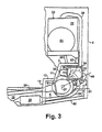
- the rear bus chassis module depicted in Figures 3, 4 and 5 is supported by a frame structure 60 to which panels belonging to the bus's fittings and body are intended to be fastened.
- This frame structure 60 incorporates a lower member 61 and an upper member 62 which both run across the whole bus.
- the lower member 61 supports not only undepicted rear suspension points for the drive unit but also a rear bumper of the bus.
- the bumper determines the bus's rear angle of interference, i.e. the angle of road ramps and the like with which the bus will cope without hitting them.
- the upper member 62 supports undepicted suspension points for the radiator arrangement and a large amount of equipment associated with the drive unit.
- the highest points of the supercharging unit and the air filter are the main factors determining the position of the seat plane 7.
- the tilt of the engine is sufficient to enable the inherently bulky inlet air lines (and also fuel lines not here depicted which belong to the fuel system) to be accommodated on top of the inlet side of the engine without requiring heightening of the seat plane 7.
- the tilt of the engine is also so great that its flywheel cover 51 constitutes the limitation on how far rearwards the floor plane 13 belonging to the rear seat 7 can extend.
- the arrangement according to the invention makes it possible to minimise the space for the type of drive unit indicated, both vertically and in the longitudinal direction of the bus. This is a prerequisite for effective utilisation, from the net load point of view, of a limited overhang rearward of the bus's rear axle while at the same time maintaining a low total bus height.
Landscapes
- Engineering & Computer Science (AREA)
- Chemical & Material Sciences (AREA)
- Combustion & Propulsion (AREA)
- Mechanical Engineering (AREA)
- General Engineering & Computer Science (AREA)
- Transportation (AREA)
- Supercharger (AREA)
- Cooling, Air Intake And Gas Exhaust, And Fuel Tank Arrangements In Propulsion Units (AREA)
Description
- Figure 1
- depicts schematically a side view of a two-axled bus with a drive unit arrangement according to the invention,
- Figure 2
- shows a view from above of the rear section of the bus depicted in Figure 1,
- Figure 3
- depicts schematically a side view of a rear section of a bus with a drive unit arrangement according to the invention,
- Figure 4
- shows a view from the rear of the bus depicted in Figure 3 and
- Figure 5
- shows a view from above of the bus depicted in Figure 3.
The highest points of the supercharging unit and the air filter are the main factors determining the position of the seat plane 7. The tilt of the engine is sufficient to enable the inherently bulky inlet air lines (and also fuel lines not here depicted which belong to the fuel system) to be accommodated on top of the inlet side of the engine without requiring heightening of the seat plane 7. The tilt of the engine is also so great that its
Claims (7)
- Bus with a front axle (1) and at least one rear axle (2), a drive unit (5) situated in the rear end of the bus and incorporating a transversely positioned combustion engine (20) with cylinders placed in line and a transmission for driving the rear axle, where the engine (20) is substantially angled so that the highest point of its cylinders is relatively close to the rear wall (9) of the bus, characterised in that the engine is supercharged and a supercharging unit (30) belonging to the engine is situated radially outside a flywheel cover (31) connected to the engine.
- Bus according to patent claim 1, characterised in that the engine has an exhaust side facing the rearward direction of the bus and an inlet side facing the forward direction of the bus, that the supercharging unit (30) is a turbo unit with a turbine (31) driven by exhaust gases and with a centrifugal compressor (32) mounted on the turbine shaft and driven by the turbine, and the turbine shaft (52) has an extent substantially transverse to the longitudinal extent of the engine, with the turbine directed towards the rear wall (9) of the bus.
- Bus according to patent claim 2, characterised in that a substantially cylindrical filter (34) for cleaning the engine's inlet air is situated in the longitudinal direction of the engine after the supercharging unit (30) above a gearbox (21) connected to the engine and forming part of the bus's transmission.
- Bus according to patent claim 3, characterised in that the supercharging unit (30) and/or the air filter (34) has/have upper limiting surfaces which essentially define an upper horizontal limiting plane which forms the base for a rear passenger bench seat (7).
- Bus according to patent claim 4, characterised in that a horizontal floor portion (13) is adapted to passengers sitting on the rear passenger bench seat (7) and has a rear limiting line which runs across the bus and which is essentially defined by an outer limiting point of the engine's flywheel cover (51).
- Bus according to any one of the foregoing patent claims, characterised in that the drive unit incorporates for the engine a radiator device (23) which is situated along the rear sidewall of the bus above the end of the engine directed away from the flywheel cover, which radiator device (23) incorporates a fan (53) which when operating pushes air down across the inlet side of the engine (20) and across other parts of the drive unit before said air leaves the drive unit space (6) via outlets in the floor portion of the latter.
- Bus according to any one of the foregoing patent claims, characterised in that the engine's valve cover/covers (47) is/are the part/parts of its fixed components which limits/limit the engine's extent rearwards in the longitudinal direction of the bus.
Applications Claiming Priority (3)
| Application Number | Priority Date | Filing Date | Title |
|---|---|---|---|
| SE9603179 | 1996-08-30 | ||
| SE9603179A SE9603179L (en) | 1996-08-30 | 1996-08-30 | Bus with transverse rear drive unit |
| PCT/SE1997/001426 WO1998008700A1 (en) | 1996-08-30 | 1997-08-28 | Bus with transversely positioned rear drive unit |
Publications (2)
| Publication Number | Publication Date |
|---|---|
| EP0921958A1 EP0921958A1 (en) | 1999-06-16 |
| EP0921958B1 true EP0921958B1 (en) | 2002-07-17 |
Family
ID=20403740
Family Applications (1)
| Application Number | Title | Priority Date | Filing Date |
|---|---|---|---|
| EP97936913A Expired - Lifetime EP0921958B1 (en) | 1996-08-30 | 1997-08-28 | Bus with transversely positioned rear drive unit |
Country Status (4)
| Country | Link |
|---|---|
| EP (1) | EP0921958B1 (en) |
| DE (1) | DE69714050T2 (en) |
| SE (1) | SE9603179L (en) |
| WO (1) | WO1998008700A1 (en) |
Families Citing this family (2)
| Publication number | Priority date | Publication date | Assignee | Title |
|---|---|---|---|---|
| WO2006094665A1 (en) | 2005-03-08 | 2006-09-14 | Kenton Srl | Chimeric recombinant antigens of toxoplasma gondii |
| CN103161566B (en) * | 2013-03-22 | 2016-10-26 | 重庆长安汽车股份有限公司 | A kind of longitudinal automobile engine and arrangement structure of turbocharger |
Family Cites Families (3)
| Publication number | Priority date | Publication date | Assignee | Title |
|---|---|---|---|---|
| US2093859A (en) * | 1936-02-17 | 1937-09-21 | Yellow Truck And Coach Mfg Com | Vehicle body |
| FR1173461A (en) * | 1956-05-11 | 1959-02-25 | Daimler Benz Ag | Axle suspension for motor cars |
| DE2934314A1 (en) * | 1979-08-24 | 1981-03-26 | Iveco Magirus Ag, 89079 Ulm | Low floor urban bus - has engine and transmission under raised rear seats |
-
1996
- 1996-08-30 SE SE9603179A patent/SE9603179L/en not_active IP Right Cessation
-
1997
- 1997-08-28 WO PCT/SE1997/001426 patent/WO1998008700A1/en not_active Ceased
- 1997-08-28 EP EP97936913A patent/EP0921958B1/en not_active Expired - Lifetime
- 1997-08-28 DE DE69714050T patent/DE69714050T2/en not_active Expired - Fee Related
Also Published As
| Publication number | Publication date |
|---|---|
| SE505631C2 (en) | 1997-09-22 |
| DE69714050D1 (en) | 2002-08-22 |
| SE9603179D0 (en) | 1996-08-30 |
| SE9603179L (en) | 1997-09-22 |
| DE69714050T2 (en) | 2003-03-06 |
| EP0921958A1 (en) | 1999-06-16 |
| WO1998008700A1 (en) | 1998-03-05 |
Similar Documents
| Publication | Publication Date | Title |
|---|---|---|
| US10287962B2 (en) | Work vehicle | |
| US20230339316A1 (en) | Side-by-side vehicle | |
| US4412515A (en) | Line multicylinder internal combustion engine | |
| US6848528B2 (en) | Lubrication system for a four cycle engine | |
| US5050701A (en) | Engine manifolding and orientation for the engine compartment of a motor vehicle | |
| US7513812B1 (en) | Marine engine | |
| US20040182621A1 (en) | Snowmobile four-cycle engine arrangement | |
| US7210562B2 (en) | Oil pan structure for four-cycle engine | |
| EP1258424B1 (en) | Vehicle, especially snowmobile, with an engine and and oil tank | |
| KR101902718B1 (en) | Work vehicle | |
| US5241926A (en) | Engine cooling apparatus | |
| US12291093B2 (en) | Off-road vehicle air intake system | |
| US5373892A (en) | Dry sump lubricated internal combustion engine with modular cooling system | |
| EP0952076A2 (en) | Scooter type vehicle | |
| KR101961060B1 (en) | Working vehicle | |
| EP0952075B1 (en) | Scooter type vehicle | |
| US4388979A (en) | Motorcycle power train arrangement | |
| EP0921958A1 (en) | Bus with transversely positioned rear drive unit | |
| US6983740B2 (en) | Internal combustion engine for a motor vehicle | |
| CA3203500A1 (en) | Off-road vehicle air intake system and windshield | |
| US12146460B2 (en) | Off-road vehicle air intake system | |
| JP2652060B2 (en) | Vehicle engine | |
| JPH08156609A (en) | Internal combustion engine layout for the vehicle | |
| JP4069579B2 (en) | Structure of 4-cycle engine for snowmobile | |
| CN118525133A (en) | Internal combustion engine for two-wheeled vehicle and two-wheeled vehicle thereof |
Legal Events
| Date | Code | Title | Description |
|---|---|---|---|
| PUAI | Public reference made under article 153(3) epc to a published international application that has entered the european phase |
Free format text: ORIGINAL CODE: 0009012 |
|
| 17P | Request for examination filed |
Effective date: 19990330 |
|
| AK | Designated contracting states |
Kind code of ref document: A1 Designated state(s): DE FR GB IT |
|
| GRAG | Despatch of communication of intention to grant |
Free format text: ORIGINAL CODE: EPIDOS AGRA |
|
| 17Q | First examination report despatched |
Effective date: 20011002 |
|
| GRAG | Despatch of communication of intention to grant |
Free format text: ORIGINAL CODE: EPIDOS AGRA |
|
| GRAH | Despatch of communication of intention to grant a patent |
Free format text: ORIGINAL CODE: EPIDOS IGRA |
|
| RIN1 | Information on inventor provided before grant (corrected) |
Inventor name: BURMAN, SAM |
|
| GRAH | Despatch of communication of intention to grant a patent |
Free format text: ORIGINAL CODE: EPIDOS IGRA |
|
| GRAA | (expected) grant |
Free format text: ORIGINAL CODE: 0009210 |
|
| AK | Designated contracting states |
Kind code of ref document: B1 Designated state(s): DE FR GB IT |
|
| PG25 | Lapsed in a contracting state [announced via postgrant information from national office to epo] |
Ref country code: IT Free format text: LAPSE BECAUSE OF FAILURE TO SUBMIT A TRANSLATION OF THE DESCRIPTION OR TO PAY THE FEE WITHIN THE PRESCRIBED TIME-LIMIT;WARNING: LAPSES OF ITALIAN PATENTS WITH EFFECTIVE DATE BEFORE 2007 MAY HAVE OCCURRED AT ANY TIME BEFORE 2007. THE CORRECT EFFECTIVE DATE MAY BE DIFFERENT FROM THE ONE RECORDED. Effective date: 20020717 |
|
| REG | Reference to a national code |
Ref country code: GB Ref legal event code: FG4D |
|
| REF | Corresponds to: |
Ref document number: 69714050 Country of ref document: DE Date of ref document: 20020822 |
|
| ET | Fr: translation filed | ||
| PLBE | No opposition filed within time limit |
Free format text: ORIGINAL CODE: 0009261 |
|
| STAA | Information on the status of an ep patent application or granted ep patent |
Free format text: STATUS: NO OPPOSITION FILED WITHIN TIME LIMIT |
|
| 26N | No opposition filed |
Effective date: 20030422 |
|
| PGFP | Annual fee paid to national office [announced via postgrant information from national office to epo] |
Ref country code: FR Payment date: 20040810 Year of fee payment: 8 |
|
| PGFP | Annual fee paid to national office [announced via postgrant information from national office to epo] |
Ref country code: GB Payment date: 20040825 Year of fee payment: 8 |
|
| PGFP | Annual fee paid to national office [announced via postgrant information from national office to epo] |
Ref country code: DE Payment date: 20040902 Year of fee payment: 8 |
|
| PG25 | Lapsed in a contracting state [announced via postgrant information from national office to epo] |
Ref country code: GB Free format text: LAPSE BECAUSE OF NON-PAYMENT OF DUE FEES Effective date: 20050828 |
|
| PG25 | Lapsed in a contracting state [announced via postgrant information from national office to epo] |
Ref country code: DE Free format text: LAPSE BECAUSE OF NON-PAYMENT OF DUE FEES Effective date: 20060301 |
|
| GBPC | Gb: european patent ceased through non-payment of renewal fee |
Effective date: 20050828 |
|
| PG25 | Lapsed in a contracting state [announced via postgrant information from national office to epo] |
Ref country code: FR Free format text: LAPSE BECAUSE OF NON-PAYMENT OF DUE FEES Effective date: 20060428 |
|
| REG | Reference to a national code |
Ref country code: FR Ref legal event code: ST Effective date: 20060428 |