EP0921918B1 - Ware forming method and apparatus - Google Patents
Ware forming method and apparatus Download PDFInfo
- Publication number
- EP0921918B1 EP0921918B1 EP97937722A EP97937722A EP0921918B1 EP 0921918 B1 EP0921918 B1 EP 0921918B1 EP 97937722 A EP97937722 A EP 97937722A EP 97937722 A EP97937722 A EP 97937722A EP 0921918 B1 EP0921918 B1 EP 0921918B1
- Authority
- EP
- European Patent Office
- Prior art keywords
- mould
- clay
- receiving member
- shaped
- shaped clay
- Prior art date
- Legal status (The legal status is an assumption and is not a legal conclusion. Google has not performed a legal analysis and makes no representation as to the accuracy of the status listed.)
- Expired - Lifetime
Links
- 238000000034 method Methods 0.000 title claims description 21
- 239000004927 clay Substances 0.000 claims description 77
- 239000000463 material Substances 0.000 claims description 11
- 239000012858 resilient material Substances 0.000 claims description 8
- 238000001514 detection method Methods 0.000 claims description 7
- 239000012530 fluid Substances 0.000 claims description 7
- XLYOFNOQVPJJNP-UHFFFAOYSA-N water Substances O XLYOFNOQVPJJNP-UHFFFAOYSA-N 0.000 claims description 3
- 238000007664 blowing Methods 0.000 claims description 2
- NIXOWILDQLNWCW-UHFFFAOYSA-N acrylic acid group Chemical group C(C=C)(=O)O NIXOWILDQLNWCW-UHFFFAOYSA-N 0.000 description 5
- 229920003023 plastic Polymers 0.000 description 5
- 239000004033 plastic Substances 0.000 description 5
- 238000001035 drying Methods 0.000 description 4
- 239000002184 metal Substances 0.000 description 4
- OSGAYBCDTDRGGQ-UHFFFAOYSA-L calcium sulfate Inorganic materials [Ca+2].[O-]S([O-])(=O)=O OSGAYBCDTDRGGQ-UHFFFAOYSA-L 0.000 description 3
- ZOMBKNNSYQHRCA-UHFFFAOYSA-J calcium sulfate hemihydrate Chemical compound O.[Ca+2].[Ca+2].[O-]S([O-])(=O)=O.[O-]S([O-])(=O)=O ZOMBKNNSYQHRCA-UHFFFAOYSA-J 0.000 description 3
- 239000011507 gypsum plaster Substances 0.000 description 3
- 239000011324 bead Substances 0.000 description 2
- 238000004519 manufacturing process Methods 0.000 description 2
- 238000012986 modification Methods 0.000 description 2
- 230000004048 modification Effects 0.000 description 2
- 229920002972 Acrylic fiber Polymers 0.000 description 1
- 230000015572 biosynthetic process Effects 0.000 description 1
- 230000001419 dependent effect Effects 0.000 description 1
- 230000002093 peripheral effect Effects 0.000 description 1
- 238000007665 sagging Methods 0.000 description 1
Images

Classifications
-
- B—PERFORMING OPERATIONS; TRANSPORTING
- B28—WORKING CEMENT, CLAY, OR STONE
- B28B—SHAPING CLAY OR OTHER CERAMIC COMPOSITIONS; SHAPING SLAG; SHAPING MIXTURES CONTAINING CEMENTITIOUS MATERIAL, e.g. PLASTER
- B28B7/00—Moulds; Cores; Mandrels
- B28B7/10—Moulds with means incorporated therein, or carried thereby, for ejecting or detaching the moulded article
- B28B7/12—Moulds with means incorporated therein, or carried thereby, for ejecting or detaching the moulded article by fluid pressure, e.g. acting through flexible wall parts or linings of the moulds
-
- B—PERFORMING OPERATIONS; TRANSPORTING
- B28—WORKING CEMENT, CLAY, OR STONE
- B28B—SHAPING CLAY OR OTHER CERAMIC COMPOSITIONS; SHAPING SLAG; SHAPING MIXTURES CONTAINING CEMENTITIOUS MATERIAL, e.g. PLASTER
- B28B13/00—Feeding the unshaped material to moulds or apparatus for producing shaped articles; Discharging shaped articles from such moulds or apparatus
- B28B13/04—Discharging the shaped articles
- B28B13/06—Removing the shaped articles from moulds
Definitions
- This invention concerns a method and apparatus for removing a piece of shaped clay from a mould.
- WO A 96/31328 discloses a method and apparatus for removing an item of shaped clay from a mould; it has been published after the priority date of the present application.
- a method of removing a piece of shaped clay from a mould comprising locating a receiving member of a resilient material against the shaped clay on the opposite side thereof to the mould, urging the receiving member against the shaped clay such that said member substantially adopts the shape of the clay to provide a close fit thereagainst, and blowing a fluid through the mould to blow the shaped clay off the mould and onto the receiving member, so that as the shaped clay is blown off the mould, the receiving member is compressed a little further to receive the shaped clay off the mould.
- the fluid preferably comprises air, and the air may be warmed.
- the receiving member preferably comprises a block of resilient material, which is desirably of greater thickness than the depth of the shaped clay.
- the receiving member may comprise a piece or pieces of resilient material mounted on a rigid support.
- the shape of the support may be adjustable, for instance to accommodate shaped articles of different depths.
- a rigid member may be provided on a part of the receiving member to provide support for a part of the shaped clay, for instance the underside of a plate within the foot.
- the receiving member may be formed such that it returns to substantially its initial shape whilst the shaped clay is thereon, after the mould has been moved away from said member.
- the resilient material may comprise a sponge or foamed material, and preferably comprises a plastics material.
- the receiving member may be shaped to support particular parts of the shaped clay when located thereon.
- the receiving member may include an upstanding annular projection for supporting the rim of shaped clay flatware.
- an upstanding projection may be provided on the receiving member which is locatable within the shaped clay. Said projection may be shaped to substantially conform to the internal profile of the shaped clay.
- the receiving member may be mounted on a carrier.
- Air which may be warmed, is preferably blown through the mould following removal of the shaped clay, to condition the mould.
- First detection means may be provided for sensing when the shaped clay has been blown off the mould, and said means may comprise second detection means for sensing a reduction in the back pressure in the mould.
- the first detection means may be connected to means for automatically separating the mould and receiving member when the shaped clay has moved onto the latter.
- the mould may be rotated relative to the receiving member once fluid is being blown through the mould, whereby to shear the water film between the mould and the clay.
- the mould may be made of an acrylic plastics material and preferably an acrylic bead.
- the plastics material is preferably mounted on a carrier.
- the carrier may be made of a plastics material such as acrylic, or of metal.
- the mould may be made of plaster of paris.
- the invention also provides apparatus for removing a piece of shaped clay from a mould, the apparatus being usable with a method according to any of the preceding thirteen paragraphs.
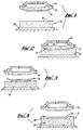
- Figs. 1 to 4 of the drawings show apparatus for removing an item of shaped clay from a mould.
- the clay is in the form of an item of flatware such as a plate.
- the drawings show a permeable synthetic mould 10.
- the mould 10 is made from an acrylic bead and has an upper surface shaped to correspond to the upper surface of a plate.
- the mould 10 is mounted on a carrier 12 also made of acrylic.
- a piece of clay is located on the mould 10.
- the mould 10 is subsequently spun and a roller head (not shown) is used to form the piece of clay into a required shape 14.
- a receiving member 16 in the form of a cylindrical block 18 of plastics material sponge on a board 20 is provided.
- the block 18 is of greater diameter than the clay 14.
- the mould 10 carrying the clay 14 is lowered on to the member 16 and pressed thereagainst such that the cylindrical block 18 adopts the shape of the underside of the clay 14 as shown in Fig. 2. Simultaneously air is blown through the mould 10 towards the clay 14.
- a chamber 22 is provided between the mould 10 and carrier 12.
- the chamber 22 is connectable to a source of above atmospheric pressure through an inlet 24. Passages (not shown) may be provided through the mould 10 to distribute above atmospheric pressure air from the chamber 22 evenly throughout the mould 10.
- the above atmospheric pressure air blown through the mould 10 will blow the clay 14 thereoff.
- the block 18 is further compressed by the clay 14 such that a gap is formed between the clay 14 and mould 10.
- the mould 10 is subsequently moved away from the receiving member 16 and the block 18 returns to its original shape as indicated in Fig. 3.
- the clay 14 carried on the member 20 can then be dried.
- As the clay 14 sits proud on the block 18 drying also takes place to a degree over the underside of the clay 14.
- the clay 14 is not on the mould 10 it can be dried relatively quickly. Warm air can be blown through the empty mould 10 to condition same by removing any moisture of other materials.
- each receiving member could be used with a wide range of different moulds thereby reducing the requirement for lots of different receiving members and also enabling short runs of different shaped articles to readily be carried out.
- FIG. 4 shows a similar apparatus to that shown in Figs. 1-3 except that the receiving member 16 comprises a block 26 which has an upstanding peripheral rim 28.
- This rim 28 provides support for the rim of the shaped clay 14 following release from the mould 10. This means that the invention would be suitable for items with thin sections to provide support for the rim prior to and during drying.
- Fig. 5 shows a further alternative receiving member 30.
- the member 30 is intended for supporting an item of flatware such as the plate 32 shown in the figure.
- the member 30 comprises a rigid metal support 34.
- the support 34 comprises an annular portion 36 which slopes downwardly towards its centre to support the rim of the plate 32, and a separate central portion 38.
- the portion 38 is mounted on a pin 40 which is slidably mounted in a frame 42 to be movable towards or away from the portion 36.
- a locking screw 44 is provided to permit the portion 38 to be locked to the frame 42 in a required position.
- the frame 42 also mounts the annular portion 36.
- Pieces of plastics material sponge 46,48 are mounted respectively on the annular and central portions 36,38.
- a relatively thin metal disc 50 is provided centrally on the piece 48, either loosely or mounted thereon.
- the disc 50 is of a smaller diameter than the piece 48.
- the receiving member 30 acts in a similar way to the receiving members 16 described above.
- the relative position of the central portion 38 is initially set dependent on the depth of the plate 32.
- the disc 50 provides support to the centre of the plate 32 to prevent sagging or collapse thereof.
- Local rigid support such as the disc 50 could be provided in different places to support parts of the clayware, and could also be used with the arrangements outlined in Figs. 1 to 4.
- the receiving members may have differently shaped blocks to provide support where required for the shaped clay. Whilst the invention is described above with regard to formation of an item of flatware, the invention is equally suited to holloware production. In this instance the block on the receiving member may be appropriately shaped and may be shaped to substantially adopt the interior shape of the holloware to provide support therefore during drying.
- the receiving member may be a different shape and/or may be made of different material.
- the invention is also readily applicable to plaster of paris moulds, or moulds made from any suitable permeable material, or which allow air to be blown through.
- Means may be provided to indicate when the clay has been blown off the mould on to the receiving member, perhaps by detecting a drop in back pressure in the mould. Said indication means may be connected to means for automatically moving the mould away from the receiving member once this "blow off" has taken place.
Landscapes
- Engineering & Computer Science (AREA)
- Ceramic Engineering (AREA)
- Manufacturing & Machinery (AREA)
- Chemical & Material Sciences (AREA)
- Mechanical Engineering (AREA)
- Physics & Mathematics (AREA)
- Fluid Mechanics (AREA)
- Devices For Post-Treatments, Processing, Supply, Discharge, And Other Processes (AREA)
- Moulds, Cores, Or Mandrels (AREA)
- Press-Shaping Or Shaping Using Conveyers (AREA)
Description
Claims (20)
- A method of removing apiece of shaped clay from a mould, characterised in that the method comprises locating a receiving member (16,30) of a resilient material against the shaped clay (14,32) on the opposite side thereof to the mould (10), urging the receiving member (16,30) against the shaped clay (14,32) such that said member (16,30) substantially adopts the shape of the clay (14,32) to provide a close fit thereagainst, and blowing a fluid through the mould (10) to blow the shaped clay (14,32) off the mould (10) and onto the receiving member (16,30), so that as the shaped clay (14,32) is blown off the mould (10), the receiving member (16,30) is compressed a little further to receive the shaped clay (14,32) off the mould (10).
- A method according to claim 1, characterised in that the fluid comprises air.
- A method according to claim 2, characterised in that the air is warmed.
- A method according to any of the claims 1 to 3, characterised in that the receiving member (16,30) is mounted on a carrier (20,42).
- A method according to any of the preceding claims, characterised in that air is blown through the mould (10) following removal of the shaped clay (14,32), to condition the mould (10).
- A method according to claim 5, characterised in that the air is warmed.
- A method according to any of the preceding claims, characterised in that first detection means is provided for sensing when the shaped clay (14,32) has been blow off the mould (10).
- A method according to claim 7, characterised in that said detection means comprises second detection means for sensing a reduction in the back pressure in the mould (10).
- A method according to claims 7 or 8, characterised in that the first detection means is connected to means for automatically separating the mould (10) and receiving member (16,30) when the shaped clay (14,32) has moved onto the latter.
- A method according to any of the preceding claims, characterised in that the mould (10) is rotated relative to the receiving member (16,30) once fluid is being blown through the mould (10), whereby to shear the water film between the mould (10) and the clay (14,32).
- Apparatus for removing a piece of shaped clay from a mould, the apparatus comprising a receiving member (16,30) locatable against the shaped clay (14,32) on the opposite side thereof to the mould (10), characterised in that the receiving member (16,30) is made of a resilient material such that when it is urged against the shaped clay (14,32) said member (16,30) substantially adopts the shape of the clay (14,32) to provide a close fit thereagainst, and when a fluid is blown through the mould (10) to blow the shaped clay (14,32) off the mould (10) and onto the receiving member (16,30), as the shaped clay (14,32) is blown off the mould (10), the receiving member (16,30) is compressed a little further to receive the shaped clay (14,32) off the mould (10).
- Apparatus according to claim 11, characterised in that the block (18,26) is of greater thickness than the depth of the shaped clay (14).
- Apparatus according to claims 11 or 12, characterised in that the receiving member (30) comprises a piece or pieces of resilient material (46,48) mounted on a rigid support (34).
- Apparatus according to any of claims 11 to 13, characterised in that a rigid member (50) is provided on a part of the receiving member (16,30) to provide support for a part of the shaped clay.
- Apparatus according to any of claims 11 to 14, characterised in that the resilient material comprises a sponge or foamed material.
- Apparatus according to any of claims 11 to 15, characterised in that the receiving member (16,30) is formed such that it returns to substantially its initial shape whilst the shaped clay (14,32) is thereon, after the mould (10) has been moved away from said member (16,30).
- Apparatus according to any of claims 11 to 16, characterised in that the receiving member (16,30) is shaped to support particular parts of the shaped clay (14,32) when located thereon.
- Apparatus according to claim 17, characterised in that the receiving member (16,30) includes an upstanding annular projection (28,36) for supporting the rim of shaped clay flatware (14,32).
- Apparatus according to claim 17, characterised in that for use with holloware an upstanding projection is provided on the receiving member (16,30) which is locatable within the shaped clay.
- Apparatus according to claim 19, characterised in that said projection is shaped to substantially conform to the internal profile of the shaped clay.
Applications Claiming Priority (3)
| Application Number | Priority Date | Filing Date | Title |
|---|---|---|---|
| GBGB9618091.4A GB9618091D0 (en) | 1996-08-29 | 1996-08-29 | Ware forming method and apparatus |
| GB9618091 | 1996-08-29 | ||
| PCT/GB1997/002297 WO1998008662A1 (en) | 1996-08-29 | 1997-08-28 | Ware forming method and apparatus |
Publications (2)
| Publication Number | Publication Date |
|---|---|
| EP0921918A1 EP0921918A1 (en) | 1999-06-16 |
| EP0921918B1 true EP0921918B1 (en) | 2001-10-31 |
Family
ID=10799146
Family Applications (1)
| Application Number | Title | Priority Date | Filing Date |
|---|---|---|---|
| EP97937722A Expired - Lifetime EP0921918B1 (en) | 1996-08-29 | 1997-08-28 | Ware forming method and apparatus |
Country Status (9)
| Country | Link |
|---|---|
| US (1) | US6238603B1 (en) |
| EP (1) | EP0921918B1 (en) |
| JP (1) | JP2000517257A (en) |
| AU (1) | AU4025497A (en) |
| DE (1) | DE69707896T2 (en) |
| ES (1) | ES2165625T3 (en) |
| GB (1) | GB9618091D0 (en) |
| PT (1) | PT921918E (en) |
| WO (1) | WO1998008662A1 (en) |
Families Citing this family (2)
| Publication number | Priority date | Publication date | Assignee | Title |
|---|---|---|---|---|
| WO2007119999A1 (en) * | 2006-04-18 | 2007-10-25 | Bo-Hyeon Yeo | Mass producing apparatus and method for clay receptacle |
| US7867418B2 (en) | 2007-09-24 | 2011-01-11 | Mars, Incorporated | Tool and apparatus for forming a moldable material |
Family Cites Families (9)
| Publication number | Priority date | Publication date | Assignee | Title |
|---|---|---|---|---|
| US2584109A (en) * | 1947-03-12 | 1952-02-05 | Ram Inc | Mold and method for molding ceramic ware |
| US2584110A (en) * | 1947-03-27 | 1952-02-05 | Ram Inc | Mold for pottery ware |
| US2632227A (en) * | 1951-01-12 | 1953-03-24 | Ram Inc | Method and apparatus for the release of ceramic ware from porous molds |
| FR2057484A5 (en) * | 1969-08-22 | 1971-05-21 | Basaltes Francais | |
| US3885522A (en) * | 1973-10-19 | 1975-05-27 | Interpace Corp | Method and apparatus of decorating a surface of an article |
| FR2343571A1 (en) * | 1976-03-11 | 1977-10-07 | Chronberg Sten | METHOD AND DEVICE FOR CUTTING AND SHAPING A SHEET OR PLATE OF A DOUGH, IN PARTICULAR BASED ON CLAY FOR THE MANUFACTURE OF CERAMIC PARTS |
| US4413966A (en) * | 1981-06-26 | 1983-11-08 | Wallace Murray Corporation | Fluid-release mold and the method of manufacturing the same |
| JPH08216142A (en) * | 1995-02-09 | 1996-08-27 | Sekisui Chem Co Ltd | Receiving of cement molded products |
| GB9506940D0 (en) * | 1995-04-04 | 1995-05-24 | British Ceramic Res Ltd | Ware forming method and apparatus |
-
1996
- 1996-08-29 GB GBGB9618091.4A patent/GB9618091D0/en active Pending
-
1997
- 1997-08-28 PT PT97937722T patent/PT921918E/en unknown
- 1997-08-28 AU AU40254/97A patent/AU4025497A/en not_active Abandoned
- 1997-08-28 WO PCT/GB1997/002297 patent/WO1998008662A1/en not_active Ceased
- 1997-08-28 DE DE69707896T patent/DE69707896T2/en not_active Expired - Fee Related
- 1997-08-28 ES ES97937722T patent/ES2165625T3/en not_active Expired - Lifetime
- 1997-08-28 EP EP97937722A patent/EP0921918B1/en not_active Expired - Lifetime
- 1997-08-28 JP JP10511378A patent/JP2000517257A/en not_active Ceased
- 1997-08-28 US US09/242,459 patent/US6238603B1/en not_active Expired - Lifetime
Also Published As
| Publication number | Publication date |
|---|---|
| DE69707896T2 (en) | 2002-06-27 |
| GB9618091D0 (en) | 1996-10-09 |
| WO1998008662A1 (en) | 1998-03-05 |
| ES2165625T3 (en) | 2002-03-16 |
| EP0921918A1 (en) | 1999-06-16 |
| JP2000517257A (en) | 2000-12-26 |
| AU4025497A (en) | 1998-03-19 |
| DE69707896D1 (en) | 2001-12-06 |
| PT921918E (en) | 2002-04-29 |
| US6238603B1 (en) | 2001-05-29 |
Similar Documents
| Publication | Publication Date | Title |
|---|---|---|
| EP0211653B1 (en) | Method for obtaining drain-cast hollow articles | |
| PL342947A1 (en) | Device and method for in-mold compression and/or in-mold injection and for edging a decorative material with a supporting material | |
| US6238603B1 (en) | Ware forming method and apparatus | |
| US5935495A (en) | Ware forming method | |
| CZ65196A3 (en) | Method of linking up a cover with a shaped stuffing by adhesion | |
| CA1130074A (en) | Vacuum forming apparatus and clamping apparatus for use therein | |
| EP1262295B1 (en) | Method and apparatus for producing single-layer tiles | |
| WO1996031328A9 (en) | Ware forming method and apparatus | |
| GB2231527A (en) | Mould release lining and mould having lining locating means | |
| EP0429853B1 (en) | Elastic forming die, method of manufacturing the same, and process for moulding a product by using the elastic forming die | |
| GB2100659A (en) | Moulds for concrete or plaster | |
| US3910547A (en) | Mold for the manufacture of an article with relief features | |
| WO2015080789A1 (en) | Decorative bowling balls and methods and apparatuses for decorating bowling balls | |
| WO1998033633A1 (en) | Ware forming | |
| EP1262296B1 (en) | Filtration structure for the pad of a press for producing single-layer cement tiles with filtration surfaces and apparatus for replacing such filtration surfaces | |
| WO2000069595A3 (en) | Method and apparatus for automatically adjusting the contour of a wafer carrier surface | |
| CN214447270U (en) | Turnover device with anti-toppling structure for soft porcelain processing | |
| JP2000238029A (en) | Mold release method and apparatus | |
| EP0567339A1 (en) | Ware shaping apparatus | |
| JP3505624B2 (en) | Method of molding using elastic mold | |
| JP2996120B2 (en) | Demolding method of pressure cast molding machine | |
| FR2527137A1 (en) | PROCESS AND DEVICE FOR DETACHING MOLDED PARTS IN TILE-TURNING PRESSES | |
| Murata | Method for Obtaining Drain-Cast Hollow Articles | |
| JPH0348005B2 (en) | ||
| JPH04156303A (en) | Demolding method of upper member of stool |
Legal Events
| Date | Code | Title | Description |
|---|---|---|---|
| PUAI | Public reference made under article 153(3) epc to a published international application that has entered the european phase |
Free format text: ORIGINAL CODE: 0009012 |
|
| 17P | Request for examination filed |
Effective date: 19990205 |
|
| AK | Designated contracting states |
Kind code of ref document: A1 Designated state(s): DE ES FR GB IT PT SE |
|
| GRAG | Despatch of communication of intention to grant |
Free format text: ORIGINAL CODE: EPIDOS AGRA |
|
| 17Q | First examination report despatched |
Effective date: 20010129 |
|
| GRAG | Despatch of communication of intention to grant |
Free format text: ORIGINAL CODE: EPIDOS AGRA |
|
| GRAH | Despatch of communication of intention to grant a patent |
Free format text: ORIGINAL CODE: EPIDOS IGRA |
|
| GRAH | Despatch of communication of intention to grant a patent |
Free format text: ORIGINAL CODE: EPIDOS IGRA |
|
| GRAA | (expected) grant |
Free format text: ORIGINAL CODE: 0009210 |
|
| AK | Designated contracting states |
Kind code of ref document: B1 Designated state(s): DE ES FR GB IT PT SE |
|
| REF | Corresponds to: |
Ref document number: 69707896 Country of ref document: DE Date of ref document: 20011206 |
|
| REG | Reference to a national code |
Ref country code: GB Ref legal event code: IF02 |
|
| REG | Reference to a national code |
Ref country code: ES Ref legal event code: FG2A Ref document number: 2165625 Country of ref document: ES Kind code of ref document: T3 |
|
| ET | Fr: translation filed | ||
| REG | Reference to a national code |
Ref country code: PT Ref legal event code: SC4A Free format text: AVAILABILITY OF NATIONAL TRANSLATION Effective date: 20020116 |
|
| PLBE | No opposition filed within time limit |
Free format text: ORIGINAL CODE: 0009261 |
|
| STAA | Information on the status of an ep patent application or granted ep patent |
Free format text: STATUS: NO OPPOSITION FILED WITHIN TIME LIMIT |
|
| 26N | No opposition filed | ||
| PGFP | Annual fee paid to national office [announced via postgrant information from national office to epo] |
Ref country code: PT Payment date: 20040812 Year of fee payment: 8 |
|
| PGFP | Annual fee paid to national office [announced via postgrant information from national office to epo] |
Ref country code: GB Payment date: 20040816 Year of fee payment: 8 |
|
| PGFP | Annual fee paid to national office [announced via postgrant information from national office to epo] |
Ref country code: SE Payment date: 20040825 Year of fee payment: 8 |
|
| PGFP | Annual fee paid to national office [announced via postgrant information from national office to epo] |
Ref country code: FR Payment date: 20040826 Year of fee payment: 8 |
|
| PGFP | Annual fee paid to national office [announced via postgrant information from national office to epo] |
Ref country code: ES Payment date: 20040827 Year of fee payment: 8 |
|
| PGFP | Annual fee paid to national office [announced via postgrant information from national office to epo] |
Ref country code: DE Payment date: 20040902 Year of fee payment: 8 |
|
| PG25 | Lapsed in a contracting state [announced via postgrant information from national office to epo] |
Ref country code: IT Free format text: LAPSE BECAUSE OF NON-PAYMENT OF DUE FEES Effective date: 20050828 Ref country code: GB Free format text: LAPSE BECAUSE OF NON-PAYMENT OF DUE FEES Effective date: 20050828 |
|
| PG25 | Lapsed in a contracting state [announced via postgrant information from national office to epo] |
Ref country code: SE Free format text: LAPSE BECAUSE OF NON-PAYMENT OF DUE FEES Effective date: 20050829 Ref country code: ES Free format text: LAPSE BECAUSE OF NON-PAYMENT OF DUE FEES Effective date: 20050829 |
|
| PG25 | Lapsed in a contracting state [announced via postgrant information from national office to epo] |
Ref country code: PT Free format text: LAPSE BECAUSE OF NON-PAYMENT OF DUE FEES Effective date: 20060228 |
|
| PG25 | Lapsed in a contracting state [announced via postgrant information from national office to epo] |
Ref country code: DE Free format text: LAPSE BECAUSE OF NON-PAYMENT OF DUE FEES Effective date: 20060301 |
|
| EUG | Se: european patent has lapsed | ||
| GBPC | Gb: european patent ceased through non-payment of renewal fee |
Effective date: 20050828 |
|
| PG25 | Lapsed in a contracting state [announced via postgrant information from national office to epo] |
Ref country code: FR Free format text: LAPSE BECAUSE OF NON-PAYMENT OF DUE FEES Effective date: 20060428 |
|
| REG | Reference to a national code |
Ref country code: FR Ref legal event code: ST Effective date: 20060428 |
|
| REG | Reference to a national code |
Ref country code: ES Ref legal event code: FD2A Effective date: 20050829 |