EP0921717B1 - Kühlsystem für eine elektrotechnische Anlage, insbesondere für einen Stromrichter insbesondere einer elektrischen Lokomotive oder eines Triebwagens - Google Patents
Kühlsystem für eine elektrotechnische Anlage, insbesondere für einen Stromrichter insbesondere einer elektrischen Lokomotive oder eines Triebwagens Download PDFInfo
- Publication number
- EP0921717B1 EP0921717B1 EP98811126A EP98811126A EP0921717B1 EP 0921717 B1 EP0921717 B1 EP 0921717B1 EP 98811126 A EP98811126 A EP 98811126A EP 98811126 A EP98811126 A EP 98811126A EP 0921717 B1 EP0921717 B1 EP 0921717B1
- Authority
- EP
- European Patent Office
- Prior art keywords
- coolant
- cooling system
- equalizing vessel
- cooling
- cooling circuit
- Prior art date
- Legal status (The legal status is an assumption and is not a legal conclusion. Google has not performed a legal analysis and makes no representation as to the accuracy of the status listed.)
- Expired - Lifetime
Links
Images

Classifications
-
- H—ELECTRICITY
- H05—ELECTRIC TECHNIQUES NOT OTHERWISE PROVIDED FOR
- H05K—PRINTED CIRCUITS; CASINGS OR CONSTRUCTIONAL DETAILS OF ELECTRIC APPARATUS; MANUFACTURE OF ASSEMBLAGES OF ELECTRICAL COMPONENTS
- H05K7/00—Constructional details common to different types of electric apparatus
- H05K7/20—Modifications to facilitate cooling, ventilating, or heating
- H05K7/20218—Modifications to facilitate cooling, ventilating, or heating using a liquid coolant without phase change in electronic enclosures
- H05K7/20272—Accessories for moving fluid, for expanding fluid, for connecting fluid conduits, for distributing fluid, for removing gas or for preventing leakage, e.g. pumps, tanks or manifolds
Definitions
- the invention relates to the field of cooling technology. She starts from one Cooling system for an electrotechnical system, in particular for a Power converter, preferably an electric locomotive or a railcar, according to the preamble of the first claim.
- a Power converter preferably an electric locomotive or a railcar
- a generic cooling system is article "high performance power converters with environmentally friendly cooling technology ", ZEV-DET glass Ann. 116 (1192) No. 8/9 August / September by Peter Heinemeyer et al. described.
- Electrical High power plants which also include converters, require a Cooling system for removing the in the elements, in particular the semiconductor devices and their wiring, resulting heat loss.
- a cooling circuit provided in which for the circulation of the coolant a pump and for cooling the coolant, a recooling device are turned on.
- a compensating vessel is connected to the circuit, the space for temperature-dependent volume changes of the coolant provides and also serves as a reservoir.
- the to be cooled Elements such as power semiconductor devices and their circuits (e.g.
- Quick-release couplings are indeed in terms of easy maintenance very pleasant. However, they are very expensive, include a variety of sealing points, require a lot of space and pose problems regarding installation tolerances. In addition, the clutches must be extremely safe. On Draining the coolant for maintenance purposes is just as undesirable, This also causes undesirable costs.
- EP 0 767 601 A1 relates to generic cooling system without Quick-release couplings, in which between an am lowest point of the closed circuit Reservoir and the highest point of the heat exchanger one always open vent line is provided, the ensures that the coolant when switching off the pump immediately runs into the reservoir. About the Vent line passes above the Coolant level located air from the reservoir the highest point of the cycle, so the Cooling circuit can run empty into the reservoir. A repair is therefore possible without that Coolant must be drained from the cooling system.
- This cooling system does not need any Quick-release couplings, but it has one the disadvantage that with the vent line a comparatively long and therefore expensive, correspondingly large dimensioned component required is to perform the desired function of emptying the Ensure cooling circuit in the reservoir.
- Another disadvantage of this cooling system is that the pump must always run to fill the cooling circuit to keep. This will happen in normal operation at each Starting the pump for a comparatively long time until the cooling system can provide its full cooling capacity.
- the object of the invention is therefore to provide a cooling system for a specify electrotechnical system, which is very easy to maintain is, without quick release couplings and can be constructed inexpensively. This task is done by the features of independent claim 1 solved.
- the core of the invention is therefore that the expansion tank on the lowest point of the cooling system is arranged and that the Equalizing vessel has sufficient free volume to the Volume of the above the expansion tank lying Record residual cycle.
- the expansion tank points According to the invention for emptying the radiator circuit to opening the cooling lock on and is for degassing of the Cooling circuit contained coolant formed. Further advantageous embodiments will be apparent from the corresponding dependent claims.
- the advantages of the invention are besides essential Cost savings due to non-use of Quick-release couplings in particular in to see the very easy maintenance.
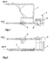
- FIG 1 shows a cooling system according to the invention from the side, Figure 2 of above.
- the cooling system is in particular for cooling the elements of a drive converter an electric locomotive suitable. It includes one Cooling circuit 1, in which coolant 3 by means of a powerful pump 2 is placed in circulation.
- a non-illustrated recooling device 4 is provided, in which the coolant 3 heat it from has taken the elements to be cooled, is withdrawn again.
- the Re-cooling device may in particular a cooling tower or a water-air heat exchanger, in which a forced air flow by means of a fan is generated.
- a compensating vessel 5 is provided, the space for temperature-dependent volume changes of the coolant and provides a reserve for low coolant losses.
- the to be cooled Elements such as power semiconductor switches, diodes, resistors, etc. are connected via connections 6 to the cooling circuit 1.
- the elements will be preferably cooled by means of coolant flowed through cooling bodies.
- the compensating vessel 5 To allow easy maintenance of the cooling system without the connections 6 equipped for the elements with expensive quick-release couplings must be the compensating vessel 5 according to the invention at the deepest Location of the cooling system arranged.
- the expansion tank in the Operation sufficient free volume on to maintain the volume of the maintenance in the cooling system above the expansion tank located part of the coolant to be able to record.
- the radiator cap 7 and a screw connection of an element the cooling circuit runs empty, and the cooling liquid thus accumulates in the expansion tank.
- the pump 2 sucks the coolant 3 from the Equalizing vessel 5 and presses it into the cooling circuit 1.
- a degassing must be provided, which contained in the cooling circuit Air removed.
- FIG. 3 shows a compensating vessel 5 with a venting box.
- 9 denotes a partition wall coolant-air, which makes it difficult to diffuse oxygen into the coolant 3.
- 11's a coolant inlet and 12 a coolant outlet.
- the expansion tank must also be dimensioned so that the coolant level 10 at rest at maximum Acceleration of the pump at most the dash-dotted, oblique line reached. If the mirror sinks further down, the pump would come out of the expansion tank again suck unwanted air in the cooling circuit.
- FIG. 4 shows an example with a so-called "degassifier”.
- This variant is Equalizing vessel cylindrical and inlet 11 and outlet 12 are offset arranged.
- the coolant through the pump placed in the expansion tank in a rotary motion. This will cause the air in pressed the middle and rises in the upper, separated by a partition wall 9 Part of the expansion tank on.
Landscapes
- Engineering & Computer Science (AREA)
- Microelectronics & Electronic Packaging (AREA)
- Physics & Mathematics (AREA)
- Thermal Sciences (AREA)
- Cooling Or The Like Of Electrical Apparatus (AREA)
- Details Of Measuring And Other Instruments (AREA)
Description
- Fig.1
- Ein erfindungsgemässes Kühlsystem von der Seite;
- Fig. 2
- Ein erfindungsgemässes Kühlsystem von oben;
- Fig. 3
- Eine erste Ausführungsform eines für die Erfindung geeigneten Ausgleichsgefässes;
- Fig. 4
- Eine zweite Ausführungsform eines für die Erfindung geeigneten Ausgleichsgefässes.
- Aufnahme des im Kühlkreislauf befindlichen Kühlmittels bei der Wartung
- Aufnahme des Expansionsvolumens bei positiver und negativer Temperaturänderung
- Entlüftung des Kreislaufs nach erfolgter Wartung
- Kein Ansaugen von Luft bei voller Beschleunigung der Pumpe aus dem Ausgleichsgefäss
- Trennen von Luft und Kühlmittel im Ausgleichsgefäss, um das Eindiffundieren von Sauerstoff in das Kühlmittel zu erschweren
- 1
- Kühlkreislauf
- 2
- Kühlmittelpumpe
- 3
- Kühlmittel
- 4
- Rückkühlvorrichtung
- 5
- Ausgleichsgefäss
- 6
- Anschluss für zu kühlende Elemente
- 7
- Kühlerverschluss
- 8
- Füll- und Entleeranschluss
- 9
- Trennwand Kühlmittel-Luft
- 10
- Kühlmittelspiegel
- 11
- Einlass
- 12
- Auslass
Claims (6)
- Kühlsystem für eine elektrotechnische Anlage, insbesondere für einen Stromrichter, vorzugsweise ein Antriebsstromrichter für die elektrische Traktionstechnik, umfassenddadurch gekennzeichnet, dass das Ausgleichsgefäß zum Entgasen des im Kühlkreislauf (1) enthaltenen Kühlmittels (3) ausgebildet ist und einen zum Entleeren des Kühlkreislaufs (1) in das Ausgleichsgefäß (5) öffenbaren Kühlerverschluss (7) aufweist.einen Kühlkreislauf (1), in welchen eine Kühlmittelpumpe (2) und eine Rückkühlvorrichtung (4) geschaltet sind, wobei die Kühlmittelpumpe (2) Kühlmittel (3) im Kühlkreislauf (1) in Umlauf setzt und die Rückkühlvorrichtung (4) dem Kühlmittel (3) aufgenommene Wärme entzieht,ein Ausgleichsgefäß (5), das an den Kühlkreislauf (1) angeschlossen ist, undeine Mehrzahl von zu kühlenden Elementen, die an Kühlkreislauf (1) angeschlossen sind, wobeidas Ausgleichsgefäß (5) an der tiefsten Stelle des Kühlsystems angeordnet ist und das Ausgleichsgefäß (5) im Betrieb des Kühlsystems mindestens ein so großes freies Volumen aufweist, dass es das Volumen des im Kühlsystem sich oberhalb des Ausgleichsgefäß (5) befindenden Teils des Kühlmittels (3) aufnehmen kann,
- Kühlsystem nach Anspruch 1, dadurch gekennzeichnet, dass das Ausgleichsgefäß (5) Mittel zum Entgasen des im Kühlerkreislauf (1) enthaltenen Kühlmittels (3) aufweist.
- Kühlsystem nach Anspruch 1 oder 2, dadurch gekennzeichnet, dass das Ausgleichsgefäß (5) nach Art eines Degasifiers ausgebildet ist.
- Kühlsystem nach Anspruch 3, dadurch gekennzeichnet, dass das Ausgleichsgefäß (5) zylindrisch ausgeführt ist und zur Erzeugung einer Drehbewegung im Kühlmittel einen Einlass (11) und einen versetzt dazu angeordneten Auslass (12) aufweist.
- Kühlsystem nach einem der vorhergehenden Ansprüche, dadurch gekennzeichnet, dass das Ausgleichsgefäß (5) zum Erschweren des Eindiffundierens von Sauerstoff in das Kühlmittel (3) eine Trennwand (9) aufweist.
- Kühlsystem nach einem der vorhergehenden Ansprüche, dadurch gekennzeichnet, dass das Ausgleichsgefäß (5) zum Verhindern des Ansaugens von Luft in den Kühlkreislauf (1) derart ausgebildet ist, dass der Kühlmittelspiegel (10) bei maximaler Beschleunigung der Kühlmittelpumpe (2) nicht bis zum Auslass (12) absinkt.
Applications Claiming Priority (2)
| Application Number | Priority Date | Filing Date | Title |
|---|---|---|---|
| DE19754284A DE19754284A1 (de) | 1997-12-08 | 1997-12-08 | Kühlsystem für eine elektrotechnische Anlage, insbesondere für einen Stromrichter insbesondere einer elektrischen Lokomotive oder eines Triebwagens |
| DE19754284 | 1997-12-08 |
Publications (3)
| Publication Number | Publication Date |
|---|---|
| EP0921717A2 EP0921717A2 (de) | 1999-06-09 |
| EP0921717A3 EP0921717A3 (de) | 1999-12-29 |
| EP0921717B1 true EP0921717B1 (de) | 2004-04-14 |
Family
ID=7851044
Family Applications (1)
| Application Number | Title | Priority Date | Filing Date |
|---|---|---|---|
| EP98811126A Expired - Lifetime EP0921717B1 (de) | 1997-12-08 | 1998-11-11 | Kühlsystem für eine elektrotechnische Anlage, insbesondere für einen Stromrichter insbesondere einer elektrischen Lokomotive oder eines Triebwagens |
Country Status (2)
| Country | Link |
|---|---|
| EP (1) | EP0921717B1 (de) |
| DE (2) | DE19754284A1 (de) |
Family Cites Families (6)
| Publication number | Priority date | Publication date | Assignee | Title |
|---|---|---|---|---|
| DE3206059C2 (de) * | 1982-02-19 | 1984-11-29 | Siemens AG, 1000 Berlin und 8000 München | Kühleinrichtung für elektrische Bauelemente |
| JPH065700B2 (ja) * | 1987-07-22 | 1994-01-19 | 株式会社日立製作所 | 電子回路デバイスの冷却装置 |
| DE4008425A1 (de) * | 1990-03-16 | 1991-09-19 | Asea Brown Boveri | Stromrichtermodul |
| JP2748732B2 (ja) * | 1991-07-19 | 1998-05-13 | 日本電気株式会社 | 液体冷媒循環システム |
| DE4209477C2 (de) * | 1992-03-24 | 1994-10-13 | Abb Patent Gmbh | Stromrichtermodul mit Kühlflüssigkeits-Strömungsbad |
| EP0767601A1 (de) * | 1995-10-02 | 1997-04-09 | General Electric Company | Mechanische Anordnung für eine mittels einer Flüssigkeit gekühlte elektronische Schaltung |
-
1997
- 1997-12-08 DE DE19754284A patent/DE19754284A1/de not_active Withdrawn
-
1998
- 1998-11-11 EP EP98811126A patent/EP0921717B1/de not_active Expired - Lifetime
- 1998-11-11 DE DE59811191T patent/DE59811191D1/de not_active Expired - Lifetime
Also Published As
| Publication number | Publication date |
|---|---|
| DE59811191D1 (de) | 2004-05-19 |
| EP0921717A3 (de) | 1999-12-29 |
| EP0921717A2 (de) | 1999-06-09 |
| DE19754284A1 (de) | 1999-06-10 |
Similar Documents
| Publication | Publication Date | Title |
|---|---|---|
| EP1540796B1 (de) | Redundantes kühlsystem mit zwei kühlkreisläufen in einem statorkühlring für einen elektrischen antriebsmotor | |
| DE69701265T2 (de) | Wandlereinrichtung für elektrische Energie für elektrische Schienenfahrzeuge | |
| EP1848260B1 (de) | Wechselrichter | |
| EP0642944B1 (de) | Kühlvorrichtung für ein Batterieladegerät und einen Bordnetzwandler in Elektrofahrzeugen | |
| DE102004063508A1 (de) | Elektrisches Bauteil mit Kühlkreislauf für den Unterwasserbetrieb | |
| EP0446836B1 (de) | Stromrichtermodul | |
| EP0705530B1 (de) | Stromrichtermodul | |
| EP1807849B1 (de) | Energiespeicher aus doppelschicht-kondensatoren, verwendung eines solchen energiespeichers bei schienenfahrzeugen und zugehöriges schienenfahrzeug | |
| WO1999066774A1 (de) | Kühlsystem für eine leistungselektronik zum betreiben wenigstens eines elektrischen aggregates eines kraftfahrzeugs | |
| DE112023001676T5 (de) | Flüssigkeitsgekühlter Schrank | |
| EP1001671B1 (de) | Vorrichtung zur unterbrechungsfreien Stromversorgung | |
| DE202004003644U1 (de) | Kühlsystem für ein elektronisches Gerät, insbesondere Computer | |
| EP2078654B1 (de) | Redundantes Klimasystem für Lokomotiven | |
| DE4307902C1 (de) | Kühlbare Einrichtung zur Aufnahme elektrischer Baugruppen | |
| DE102004054060B3 (de) | Energiespeicher aus Doppelschicht-Kondensatoren und Verwendung eines solchen Energiespeichers bei Schienenfahrzeugen | |
| DE3914412A1 (de) | System zur nutzung der abwaerme einer flaschenreinigungsmaschine | |
| EP0921717A2 (de) | Kühlsystem für eine elektrotechnische Anlage, insbesondere für einen Stromrichter insbesondere einer elektrischen Lokomotive oder eines Triebwagens | |
| DE3918593A1 (de) | Verfahren und anordnung zur abschaltung eines im abgasstrom eines verbrennungsmotors angeordneten, mit einem fliessfaehigen waermetraeger betriebenen waermetauschers | |
| DE4307061A1 (de) | Vorrichtung zur Abführung der Verlustwärme aus gerätebestückten Gehäusen | |
| DE29622811U1 (de) | Kühlsystem für eine Traktionseinrichtung | |
| DE102021113223A1 (de) | Vorrichtung und Verfahren zu einem ölgekühlten Batteriemanagementsystem einer Hochvolt-Batterie | |
| DE102023109532B4 (de) | Kühlsystem zur Kühlung eines batterieelektrischen Fahrzeugs | |
| DE19535310A1 (de) | Kühleinrichtung für Textilmaschine | |
| WO2014187587A1 (de) | Gleichspannungswandler und brennstoffzellenanlage eines unterseebootes | |
| DE7900902U1 (de) | Sonnenenergiekollektor |
Legal Events
| Date | Code | Title | Description |
|---|---|---|---|
| PUAI | Public reference made under article 153(3) epc to a published international application that has entered the european phase |
Free format text: ORIGINAL CODE: 0009012 |
|
| AK | Designated contracting states |
Kind code of ref document: A2 Designated state(s): CH DE FR IT LI |
|
| AX | Request for extension of the european patent |
Free format text: AL;LT;LV;MK;RO;SI |
|
| PUAL | Search report despatched |
Free format text: ORIGINAL CODE: 0009013 |
|
| AK | Designated contracting states |
Kind code of ref document: A3 Designated state(s): AT BE CH CY DE DK ES FI FR GB GR IE IT LI LU MC NL PT SE |
|
| AX | Request for extension of the european patent |
Free format text: AL;LT;LV;MK;RO;SI |
|
| RIC1 | Information provided on ipc code assigned before grant |
Free format text: 6H 05K 7/20 A, 6H 02M 7/00 B |
|
| 17P | Request for examination filed |
Effective date: 20000325 |
|
| RAP1 | Party data changed (applicant data changed or rights of an application transferred) |
Owner name: DAIMLERCHRYSLER AG |
|
| AKX | Designation fees paid |
Free format text: CH DE FR IT LI |
|
| RAP1 | Party data changed (applicant data changed or rights of an application transferred) |
Owner name: DAIMLERCHRYSLER RAIL SYSTEMS GMBH |
|
| 17Q | First examination report despatched |
Effective date: 20030228 |
|
| GRAP | Despatch of communication of intention to grant a patent |
Free format text: ORIGINAL CODE: EPIDOSNIGR1 |
|
| GRAS | Grant fee paid |
Free format text: ORIGINAL CODE: EPIDOSNIGR3 |
|
| GRAA | (expected) grant |
Free format text: ORIGINAL CODE: 0009210 |
|
| AK | Designated contracting states |
Kind code of ref document: B1 Designated state(s): CH DE FR IT LI |
|
| REG | Reference to a national code |
Ref country code: CH Ref legal event code: EP |
|
| RAP2 | Party data changed (patent owner data changed or rights of a patent transferred) |
Owner name: BOMBARDIER TRANSPORTATION GMBH |
|
| REF | Corresponds to: |
Ref document number: 59811191 Country of ref document: DE Date of ref document: 20040519 Kind code of ref document: P |
|
| ET | Fr: translation filed | ||
| PLBE | No opposition filed within time limit |
Free format text: ORIGINAL CODE: 0009261 |
|
| STAA | Information on the status of an ep patent application or granted ep patent |
Free format text: STATUS: NO OPPOSITION FILED WITHIN TIME LIMIT |
|
| 26N | No opposition filed |
Effective date: 20050117 |
|
| PGFP | Annual fee paid to national office [announced via postgrant information from national office to epo] |
Ref country code: FR Payment date: 20141119 Year of fee payment: 17 Ref country code: CH Payment date: 20141119 Year of fee payment: 17 Ref country code: DE Payment date: 20141119 Year of fee payment: 17 |
|
| PGFP | Annual fee paid to national office [announced via postgrant information from national office to epo] |
Ref country code: IT Payment date: 20141124 Year of fee payment: 17 |
|
| REG | Reference to a national code |
Ref country code: DE Ref legal event code: R119 Ref document number: 59811191 Country of ref document: DE |
|
| REG | Reference to a national code |
Ref country code: CH Ref legal event code: PL |
|
| PG25 | Lapsed in a contracting state [announced via postgrant information from national office to epo] |
Ref country code: CH Free format text: LAPSE BECAUSE OF NON-PAYMENT OF DUE FEES Effective date: 20151130 Ref country code: IT Free format text: LAPSE BECAUSE OF NON-PAYMENT OF DUE FEES Effective date: 20151111 Ref country code: LI Free format text: LAPSE BECAUSE OF NON-PAYMENT OF DUE FEES Effective date: 20151130 |
|
| REG | Reference to a national code |
Ref country code: FR Ref legal event code: ST Effective date: 20160729 |
|
| PG25 | Lapsed in a contracting state [announced via postgrant information from national office to epo] |
Ref country code: DE Free format text: LAPSE BECAUSE OF NON-PAYMENT OF DUE FEES Effective date: 20160601 |
|
| PG25 | Lapsed in a contracting state [announced via postgrant information from national office to epo] |
Ref country code: FR Free format text: LAPSE BECAUSE OF NON-PAYMENT OF DUE FEES Effective date: 20151130 |