EP0920807B1 - System for moving animals towards a point of slaughter - Google Patents
System for moving animals towards a point of slaughter Download PDFInfo
- Publication number
- EP0920807B1 EP0920807B1 EP97309040A EP97309040A EP0920807B1 EP 0920807 B1 EP0920807 B1 EP 0920807B1 EP 97309040 A EP97309040 A EP 97309040A EP 97309040 A EP97309040 A EP 97309040A EP 0920807 B1 EP0920807 B1 EP 0920807B1
- Authority
- EP
- European Patent Office
- Prior art keywords
- urging device
- raceway
- urging
- animal
- point
- Prior art date
- Legal status (The legal status is an assumption and is not a legal conclusion. Google has not performed a legal analysis and makes no representation as to the accuracy of the status listed.)
- Expired - Lifetime
Links
- 241001465754 Metazoa Species 0.000 title claims abstract description 48
- 238000003307 slaughter Methods 0.000 title claims abstract description 17
- 238000000034 method Methods 0.000 claims description 9
- 241000282887 Suidae Species 0.000 description 21
- 230000035882 stress Effects 0.000 description 5
- 235000013372 meat Nutrition 0.000 description 2
- 241000894007 species Species 0.000 description 2
- 238000005266 casting Methods 0.000 description 1
- 238000010276 construction Methods 0.000 description 1
- 230000009429 distress Effects 0.000 description 1
- 244000144980 herd Species 0.000 description 1
- 238000004519 manufacturing process Methods 0.000 description 1
Images



Classifications
-
- A—HUMAN NECESSITIES
- A22—BUTCHERING; MEAT TREATMENT; PROCESSING POULTRY OR FISH
- A22B—SLAUGHTERING
- A22B1/00—Apparatus for fettering animals to be slaughtered
-
- A—HUMAN NECESSITIES
- A01—AGRICULTURE; FORESTRY; ANIMAL HUSBANDRY; HUNTING; TRAPPING; FISHING
- A01K—ANIMAL HUSBANDRY; AVICULTURE; APICULTURE; PISCICULTURE; FISHING; REARING OR BREEDING ANIMALS, NOT OTHERWISE PROVIDED FOR; NEW BREEDS OF ANIMALS
- A01K1/00—Housing animals; Equipment therefor
- A01K1/0005—Stable partitions
- A01K1/0017—Gates, doors
- A01K1/0029—Crowding gates or barriers
Definitions
- the present invention relates to a system for moving one or more animals towards a point of slaughter.
- GB-A-2211389 uses a gate which travels along the raceway, and lifts and returns above the heads of the following pigs. This system suffers from a number of problems. Firstly, a complex support framework is required to lift and return the gate. Secondly, the movement of the gate over the heads of the following pigs induces high levels of stress which can result in reduced meat quality.
- a system for moving one or more animals towards a point of slaughter comprising confinement means for confining the animals in a raceway; and an urging device having
- the system according to the present invention is particularly simple and inexpensive to manufacture and use.
- the urging device can be easily installed in an existing raceway. Further, the urging device does not need to return above the heads of the following animals and therefore induces less stress than previous urging devices, giving an improvement in meat quality.
- the urging device may comprise a single member which expands uniformly, for instance by being blown up with air.
- the urging device comprises a base; an urging member; and an expandable connector which connects the urging member to the base.
- the expandable connector may comprise a hydraulic or pneumatic cylinder which expands in the direction of expansion of the urging member.
- the expandable connector comprises a linkage mechanism, typically comprising one or more pairs of rods, each rod being pivoted at an intermediate point along its length to the other rod in the pair, and each rod being pivoted at each end to the end of an adjacent rod, to the base, or to the urging member.
- the linkage mechanism can then be operated by driving the end of one of the rods (in the manner of a scissor mechanism).
- the linkage mechanism comprises two or more pairs of rods - this gives greater expansion for a given movement of the driven rod.
- the base has a substantially planar rear surface. This induces less stress in the following animals.
- the urging member has a substantially planar front surface.
- the urging member can contact the animals without cause damage or distress.
- the urging device may move between its closed and open positions in any required manner.
- the urging device may be pivoted to the confinement means (eg a side wall) such that in its closed position the urging device lies flat against the side wall.
- the urging device is slid between its open and closed positions.
- the urging device In its open position the urging device may be above or below the raceway. However preferably in its open position the urging device is on one side of the raceway. As a result no support structures are required above the animal(s).
- the system further comprises a sensor which senses contact between the urging device and an animal as the urging device is moved from its open position to its closed position, and stops or reverses the movement of the urging device if contact is sensed.
- the confinement means may comprise any suitable structure for confining the animal(s) to a desired location.
- the confinement means comprises one or more side walls.
- the confinement means comprises a side wall having an opening through which the urging device can be moved between its open and closed positions.
- a plurality of urging devices may be provided.
- a pair of urging devices is provided.
- the system may be used to control any suitable species of animal, including pigs.
- a method of moving one or more animals along a raceway towards a point of slaughter comprising
- the method can be repeated if necessary to move one or more following batches of animals by
- the method further comprises providing a second urging device, and carrying out steps a) to d) with the second urging device out of phase with the first device whereby when each urging device is expanded the other urging device is in its open position.
- a system for moving batches of pigs from a lairage (not shown) located to the left of the system of Figure 1, to a CO 2 stunning unit (not shown) to the right of the system of Figure 1 comprises a pair of side walls 1,2 whose inner surfaces are spaced apart by a distance 3 of 900mm.
- the walls 1,2 define a raceway through which batches of pigs are led as indicated at 4.
- the walls 1,2 each have one or more staggered obstructions 5,6 etc. which create a series of bends in the raceway, thus preventing oncoming batches of pigs from being able to see along the entire length of the raceway. This reduces the level of stress in the oncoming batches of pigs.
- a pair of lairage side gates 7,8 of identical construction, are supported on respective carriages 9,10 on one side of the raceway.
- the gates 7,8 have a width of approximately 1000mm and are shown in Figure 1 in solid lines in their closed position in the raceway, and in dotted lines at 11,12 in their open position at the side of the raceway.
- the lairage side gate 8 comprises a frame 13 having a planar rear surface, with a horizontal deployment bar 14 slidably mounted in carriage 10 on linear bearings 15,16.
- the gate 8 and deployment bar 14 are shown in solid lines in Figure 2 in their closed position, and in dotted lines in their open position to one side of the raceway.
- the gate 8 is driven between its closed and open positions (as indicated at 17) by a pneumatic cylinder (not shown).
- the exhausts from the pneumatic cylinder and valves are piped away so that the noise of hissing spent air does not upset the pigs.
- the gates 7,8 each have a pusher plate 18,19. Batches of pigs are urged along the raceway by movement of the pusher plates 18,19 as indicated at 20,21.
- the rear pusher plate 18 is shown in its retracted position
- the front pusher plate 19 is shown in its retracted position and in its extended position.
- the pusher plates 18,19 are mounted to their respective frames by a parallelogram linkage mechanism.
- the linkage mechanism of the front gate 8 is illustrated in Figure 3 with the pusher plate 19 in its retracted and extended position.
- the linkage mechanism comprises four rods 50-53 pivoted to each other at their ends 23,24 and at their centres at 25,26.
- Rod 51 is pivoted to the frame 13 at 27, and rod 52 is pivoted to the pusher plate 19 at 28.
- the end 30 of rod 53 is slidably mounted in the pusher plate 19, and the end 29 of rod 50 is driven up and down inside the frame 13 by a pneumatic cylinder (not shown).
- the pusher plate 19 is driven between its extended position and its retracted position in which the linkage mechanism is housed in a cavity inside the frame 13.
- the pneumatic system (not shown) for driving the pusher plates 18,19 is also exhausted away from the raceway so that the noise of hissing spent air does not upset the pigs.
- the gates 7,8 each have a contact sensor 31,32 which reverses the movement of the gate into the raceway if the gate contacts a pig as it is being moved across the raceway.
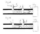
- FIGS 4A and 4B Operation of the system of Figures 1-3 is illustrated in Figures 4A and 4B which also illustrate a CO 2 stunning unit 43.
- the gates 7,8 and stunning unit 43 define a first compartment 40 and a second compartment 41.
- gate 7 open and gate 8 closed Figure 4A
- pigs will naturally walk into the first compartment 40 because of their inquisitive nature.
- gate 7 closes across the raceway to hold back the following pigs.
- Gate 8 then retracts to the position shown in Figure 4B and the pushing plate 18 within gate 7 begins to extend to gently push the pigs into the second compartment 41.
- the gate 8 slides to its closed position across the raceway, and the pusher plate 18 retracts and the gate 7 moves back to its open position at the side of the raceway ready for the next batch of three pigs.
- the pusher plate 19 within the gate 8 then gently pushes the pigs into the CO 2 standing unit 43 ( Figure 4A). The pusher plate 19 then retracts ready for the next cycle.
- system has been illustrated for pigs, the system can be used with any species of animal in the lairage environment.
- batches of three pigs are used in the system illustrated, any number of pigs can be used, for instance the compartments 40,41 could house batches of one, two or more than three pigs.
Landscapes
- Life Sciences & Earth Sciences (AREA)
- Environmental Sciences (AREA)
- Engineering & Computer Science (AREA)
- Food Science & Technology (AREA)
- Zoology (AREA)
- Animal Husbandry (AREA)
- Biodiversity & Conservation Biology (AREA)
- Catching Or Destruction (AREA)
- Housing For Livestock And Birds (AREA)
- Feed For Specific Animals (AREA)
Abstract
Description
- The present invention relates to a system for moving one or more animals towards a point of slaughter.
- The traditional way of moving animals through a lairage to the point of stunning is for a stockman to herd them down the raceway.
- A number of automatic lairage gates have been designed and some have been produced commercially. GB-A-2211389 uses a gate which travels along the raceway, and lifts and returns above the heads of the following pigs. This system suffers from a number of problems. Firstly, a complex support framework is required to lift and return the gate. Secondly, the movement of the gate over the heads of the following pigs induces high levels of stress which can result in reduced meat quality.
- In accordance with a first aspect of the present invention there is provided a system for moving one or more animals towards a point of slaughter comprising confinement means for confining the animals in a raceway; and an urging device having
- a) an open position in which the animal(s) can pass along the raceway in front of the urging device, and
- b) a closed position in which it extends across the raceway to prevent following animals from passing along the raceway in front of the urging device and in which it can be expanded to urge the animal(s) which have already passed it towards the point of slaughter.
-
- The system according to the present invention is particularly simple and inexpensive to manufacture and use. In addition, the urging device can be easily installed in an existing raceway. Further, the urging device does not need to return above the heads of the following animals and therefore induces less stress than previous urging devices, giving an improvement in meat quality.
- The urging device may comprise a single member which expands uniformly, for instance by being blown up with air. However preferably the urging device comprises a base; an urging member; and an expandable connector which connects the urging member to the base.
- The expandable connector may comprise a hydraulic or pneumatic cylinder which expands in the direction of expansion of the urging member. However, in a preferred example the expandable connector comprises a linkage mechanism, typically comprising one or more pairs of rods, each rod being pivoted at an intermediate point along its length to the other rod in the pair, and each rod being pivoted at each end to the end of an adjacent rod, to the base, or to the urging member. The linkage mechanism can then be operated by driving the end of one of the rods (in the manner of a scissor mechanism).
- Typically the linkage mechanism comprises two or more pairs of rods - this gives greater expansion for a given movement of the driven rod.
- Typically adjacent pairs of rods are arranged to define a parallelogram.
- Preferably the base has a substantially planar rear surface. This induces less stress in the following animals.
- Preferably the urging member has a substantially planar front surface. As a result the urging member can contact the animals without cause damage or distress.
- The urging device may move between its closed and open positions in any required manner. For instance the urging device may be pivoted to the confinement means (eg a side wall) such that in its closed position the urging device lies flat against the side wall. However preferably the urging device is slid between its open and closed positions.
- In its open position the urging device may be above or below the raceway. However preferably in its open position the urging device is on one side of the raceway. As a result no support structures are required above the animal(s).
- If the urging device contacts an animal as it moves to its closed position, it may trap the animal, and/or induce stress in the animal. Therefore preferably the system further comprises a sensor which senses contact between the urging device and an animal as the urging device is moved from its open position to its closed position, and stops or reverses the movement of the urging device if contact is sensed.
- The confinement means may comprise any suitable structure for confining the animal(s) to a desired location. However preferably the confinement means comprises one or more side walls. Typically the confinement means comprises a side wall having an opening through which the urging device can be moved between its open and closed positions.
- If further control over movement is required, a plurality of urging devices may be provided. In a preferred embodiment a pair of urging devices is provided.
- The system may be used to control any suitable species of animal, including pigs.
- In accordance with a second aspect of the present invention there is provided a method of moving one or more animals along a raceway towards a point of slaughter, the method comprising
- a) arranging a first urging device in an open position in which the animal(s) can move along the raceway past the urging device;
- b) moving the urging device into a closed position behind the animal(s) in which it extends across the raceway to prevent following animals from moving along the raceway past the urging device; and
- c) expanding the urging device to urge the animal(s) which have already passed it towards the point of slaughter.
-
- The method can be repeated if necessary to move one or more following batches of animals by
- d) contracting the urging device; and
- e) repeating steps a) to d) one or more times to move the one or more following batches of animals towards the point of slaughter.
-
- In a preferred embodiment the method further comprises providing a second urging device, and carrying out steps a) to d) with the second urging device out of phase with the first device whereby when each urging device is expanded the other urging device is in its open position.
- An embodiment of the present invention will now be described with reference to the accompanying drawings, in which:-
- Figure 1 is a plan view of an example of a system for moving one or more animals towards a point of slaughter;
- Figure 2 is a front view in direction A of the system in Figure 1;
- Figure 3 is a cross-section along line B of the system of Figure 1 with the right hand gate expanded and positioned in the raceway, and the left hand gate retracted in its positioned to one side of the raceway; and,
- Figures 4A and 4B illustrate a method of urging one or more animals towards a point of slaughter using the system of Figures 1-3.
-
- Referring to Figures 1-3, a system for moving batches of pigs from a lairage (not shown) located to the left of the system of Figure 1, to a CO2 stunning unit (not shown) to the right of the system of Figure 1 comprises a pair of side walls 1,2 whose inner surfaces are spaced apart by a distance 3 of 900mm. The walls 1,2 define a raceway through which batches of pigs are led as indicated at 4. The walls 1,2 each have one or more
staggered obstructions 5,6 etc. which create a series of bends in the raceway, thus preventing oncoming batches of pigs from being able to see along the entire length of the raceway. This reduces the level of stress in the oncoming batches of pigs. - A pair of
lairage side gates respective carriages 9,10 on one side of the raceway. Thegates - Referring to Figure 2, the
lairage side gate 8 comprises aframe 13 having a planar rear surface, with ahorizontal deployment bar 14 slidably mounted incarriage 10 onlinear bearings gate 8 anddeployment bar 14 are shown in solid lines in Figure 2 in their closed position, and in dotted lines in their open position to one side of the raceway. Thegate 8 is driven between its closed and open positions (as indicated at 17) by a pneumatic cylinder (not shown). The exhausts from the pneumatic cylinder and valves are piped away so that the noise of hissing spent air does not upset the pigs. - As can be seen in Figure 2, with the
gate 8 open, there is no support framework remaining above the pigs casting shadows in their path. - The
gates pusher plate pusher plates rear pusher plate 18 is shown in its retracted position, and in Figures 1 and 3 thefront pusher plate 19 is shown in its retracted position and in its extended position. - The
pusher plates front gate 8 is illustrated in Figure 3 with thepusher plate 19 in its retracted and extended position. The linkage mechanism comprises four rods 50-53 pivoted to each other at theirends 23,24 and at their centres at 25,26.Rod 51 is pivoted to theframe 13 at 27, and rod 52 is pivoted to thepusher plate 19 at 28. The end 30 ofrod 53 is slidably mounted in thepusher plate 19, and theend 29 ofrod 50 is driven up and down inside theframe 13 by a pneumatic cylinder (not shown). Hence by driving theend 29 ofrod 50, thepusher plate 19 is driven between its extended position and its retracted position in which the linkage mechanism is housed in a cavity inside theframe 13. The pneumatic system (not shown) for driving thepusher plates - The
gates contact sensor - Operation of the system of Figures 1-3 is illustrated in Figures 4A and 4B which also illustrate a CO2
stunning unit 43. Thegates stunning unit 43 define afirst compartment 40 and asecond compartment 41. Withgate 7 open andgate 8 closed (Figure 4A), pigs will naturally walk into thefirst compartment 40 because of their inquisitive nature. When three pigs are in thefirst compartment 40,gate 7 closes across the raceway to hold back the following pigs.Gate 8 then retracts to the position shown in Figure 4B and the pushingplate 18 withingate 7 begins to extend to gently push the pigs into thesecond compartment 41. At this point, thegate 8 slides to its closed position across the raceway, and thepusher plate 18 retracts and thegate 7 moves back to its open position at the side of the raceway ready for the next batch of three pigs. Thepusher plate 19 within thegate 8 then gently pushes the pigs into the CO2 standing unit 43 (Figure 4A). Thepusher plate 19 then retracts ready for the next cycle. - The eight steps in a single cycle are illustrated below in Table 1. As can be seen in Table 1, the two gates are operated out of phase with each other such that when each gate is extended, the other gate is open.
REAR GATE 7FRONT GATE 8Close Open Expand Contract Close Open Expand Contract - Two
gates - Although the system has been illustrated for pigs, the system can be used with any species of animal in the lairage environment.
- Although batches of three pigs are used in the system illustrated, any number of pigs can be used, for instance the
compartments
Claims (15)
- A system for moving one or more animals towards a point of slaughter comprising confinement means for confining the animals in a raceway; and an urging device havinga) an open position in which the animal(s) can move along the raceway past the urging device, andb) a closed position in which it extends across the raceway to prevent following animals from moving along the raceway past the urging device and in which it can be expanded to urge the animal(s) which have already passed it towards the point of slaughter.
- A system according to claim 1 wherein the urging device comprises a base; an urging member; and an expandable connector which connects the urging member to the base.
- A system according to claim 2 wherein the expandable connector comprises a linkage mechanism comprising one or more pairs of rods, each rod being pivoted at an intermediate point along its length to the other rod in the pair, and each rod being pivoted at each end to the end of an adjacent rod, to the base, or to the urging member.
- A system according to claim 3 wherein the linkage mechanism comprises two or more pairs of rods.
- A system according to claim 4 wherein each pair of adjacent pairs of rods is arranged to define a parallelogram.
- A system according to any of claims 2 to 5 wherein the base has a substantially planar rear surface.
- A system according to any of claims 2 to 6 wherein the urging member has a substantially planar front surface.
- A system according to any of the preceding claims wherein in its open position the urging device is on one side of the raceway position.
- A system according to any of the preceding claims wherein the urging device is slid between its open and closed positions.
- A system according to any of the preceding claims further comprising a sensor which senses contact between the urging device and an animal as the urging device is moved from its open position to its closed position, and stops or reverses the movement of the urging device if contact is sensed.
- A system according to any of the preceding claims wherein the confinement means comprises a side wall having an opening through which the urging device can be moved between its two positions.
- A system according to any of the preceding claims further comprising one or more additional urging devices, each havinga) an open position in which the animal(s) can pass along the raceway in front of the urging device, andb) a closed position in which it extends across the raceway to prevent following animals from passing along the raceway in front of the urging device and in which it can be expanded to urge the animal(s) which have already passed it towards the point of slaughter.
- A method of moving one or more animals along a raceway towards a point of slaughter, the method comprisinga) arranging a first urging device in an open position in which the animal(s) can move along the raceway past the urging device;b) moving the urging device into a closed position behind the animal(s) in which it extends across the raceway to prevent following animals from moving along the raceway past the urging device; andc) expanding the urging device to urge the animal(s) which have already passed it towards the point of slaughter.
- A method according to claim 13 further comprisingd) contracting the urging device; ande) repeating steps a) to d) one or more times to move one or more following batches of animals towards the point of slaughter.
- A method according to claim 13 or 14 further comprising providing a second urging device, and carrying out steps a) to d) with the second urging device out of phase with the first device whereby when each urging device is expanded the other urging device is in its open position.
Priority Applications (4)
| Application Number | Priority Date | Filing Date | Title |
|---|---|---|---|
| DE69704164T DE69704164D1 (en) | 1997-11-11 | 1997-11-11 | Plant for driving animals to a slaughter station |
| EP97309040A EP0920807B1 (en) | 1997-11-11 | 1997-11-11 | System for moving animals towards a point of slaughter |
| DK97309040T DK0920807T3 (en) | 1997-11-11 | 1997-11-11 | System for moving animals towards a slaughterhouse |
| AT97309040T ATE199301T1 (en) | 1997-11-11 | 1997-11-11 | SYSTEM FOR DRIVING ANIMALS TO A SLAUGHTER STATION |
Applications Claiming Priority (1)
| Application Number | Priority Date | Filing Date | Title |
|---|---|---|---|
| EP97309040A EP0920807B1 (en) | 1997-11-11 | 1997-11-11 | System for moving animals towards a point of slaughter |
Publications (2)
| Publication Number | Publication Date |
|---|---|
| EP0920807A1 EP0920807A1 (en) | 1999-06-09 |
| EP0920807B1 true EP0920807B1 (en) | 2001-02-28 |
Family
ID=8229609
Family Applications (1)
| Application Number | Title | Priority Date | Filing Date |
|---|---|---|---|
| EP97309040A Expired - Lifetime EP0920807B1 (en) | 1997-11-11 | 1997-11-11 | System for moving animals towards a point of slaughter |
Country Status (4)
| Country | Link |
|---|---|
| EP (1) | EP0920807B1 (en) |
| AT (1) | ATE199301T1 (en) |
| DE (1) | DE69704164D1 (en) |
| DK (1) | DK0920807T3 (en) |
Families Citing this family (5)
| Publication number | Priority date | Publication date | Assignee | Title |
|---|---|---|---|---|
| DK174453B1 (en) * | 2001-12-06 | 2003-03-24 | Slagteriernes Forskningsinst | Stunning apparatus for slaughter animals has driving corridor with driving gate system comprising driving gate, conveyance devices and controller, stunning box and fixation devices |
| DK174938B1 (en) * | 2002-03-27 | 2004-03-08 | Slagteriernes Forskningsinst | Equipment, drive and method of propelling animals in an elongated walkway |
| WO2014027901A1 (en) | 2012-08-16 | 2014-02-20 | HARRIS, Catherine Michelle | Improvements in animal handling systems |
| CN112261869A (en) * | 2018-06-19 | 2021-01-22 | 利拉伐控股有限公司 | Method and control unit for controlling a movable catch-up gate |
| CN111700095B (en) * | 2020-06-29 | 2024-10-29 | 安徽聚丰畜禽开发有限公司 | Binding equipment for pig slaughtering |
Family Cites Families (5)
| Publication number | Priority date | Publication date | Assignee | Title |
|---|---|---|---|---|
| DK110107C (en) * | 1966-07-12 | 1968-12-02 | Slagteriernes Forskningsinst | Collection facilities for slaughter animals, in particular pigs. |
| DK552887A (en) * | 1987-10-22 | 1989-04-23 | Slagteriernes Forskningsinst | PROCEDURES FOR TREATING Slaughter pigs at slaughterhouses and facilities for the preparation of slaughter pigs |
| US4951608A (en) * | 1989-05-15 | 1990-08-28 | Reisgies Rolf W | Brisket bar apparatus for controlling the positioning and movement of cows in a milking parlor |
| DK33490D0 (en) * | 1990-02-08 | 1990-02-08 | Slagteriernes Forskningsinst | PROCEDURE AND ESTABLISHMENT FOR STUNNING ANIMALS IN Slaughterhouses |
| DE29507943U1 (en) * | 1995-05-17 | 1995-09-21 | Vogt-Werke GmbH & Co KG, 36381 Schlüchtern | Temporary partition |
-
1997
- 1997-11-11 AT AT97309040T patent/ATE199301T1/en not_active IP Right Cessation
- 1997-11-11 DK DK97309040T patent/DK0920807T3/en active
- 1997-11-11 DE DE69704164T patent/DE69704164D1/en not_active Expired - Lifetime
- 1997-11-11 EP EP97309040A patent/EP0920807B1/en not_active Expired - Lifetime
Also Published As
| Publication number | Publication date |
|---|---|
| DK0920807T3 (en) | 2001-06-25 |
| DE69704164D1 (en) | 2001-04-05 |
| ATE199301T1 (en) | 2001-03-15 |
| EP0920807A1 (en) | 1999-06-09 |
Similar Documents
| Publication | Publication Date | Title |
|---|---|---|
| EP0643917B1 (en) | Apparatus for separating a flock of animals into groups | |
| EP0920807A1 (en) | System for moving animals towards a point of slaughter | |
| DK1523880T3 (en) | Device and method of feeding and milking animals | |
| ITTO20020066A1 (en) | METHOD AND SYSTEM FOR THE TRANSPORT OF LIVE POULTRY. | |
| US5230299A (en) | Telescoping entry gate for milking parlor | |
| DE3871323D1 (en) | SWITCH FOR A FLOOR TRANSPORTER SYSTEM. | |
| SE8107866L (en) | DISPOSAL AND EMPTYING DEVICE | |
| US5042392A (en) | Floor mounted walking beam system for advancing a vehicle | |
| EP0072596B1 (en) | Drive corridor for slaughter cattle | |
| US5913286A (en) | Method and apparatus for loading poultry through a vision blocking gate | |
| JPWO2020050087A1 (en) | Induction number control device for livestock and reverse invasion control device | |
| EP0909125B1 (en) | Hen nesting apparatus and brood control method | |
| US6477984B1 (en) | Gate assembly for confining animals in an alley | |
| US10144067B2 (en) | Bar feeding device | |
| US1769201A (en) | Bake-oven-feeding apparatus | |
| DE60016677D1 (en) | A medal game machine | |
| CN110654823A (en) | Biological medium conveying equipment in sterilizer | |
| ATE143343T1 (en) | CONVEYOR SYSTEM FOR CONVEYING OBJECTS IN SPACE | |
| EP0220961A2 (en) | Mechanical handling apparatus | |
| EP1489913B1 (en) | Arrangement and method for division of animals into groups and transfer of groups of animals to a stunning apparatus | |
| SU665863A1 (en) | Animal-breeding room | |
| IT1315154B1 (en) | DEVICE FOR COMPLETING REINFORCEMENT CAGES AND RELATED PROCEDURE. | |
| US2093818A (en) | Shooting range apparatus | |
| SU1484795A1 (en) | Device for transfering articles | |
| US3005538A (en) | Conveyor |
Legal Events
| Date | Code | Title | Description |
|---|---|---|---|
| PUAI | Public reference made under article 153(3) epc to a published international application that has entered the european phase |
Free format text: ORIGINAL CODE: 0009012 |
|
| AK | Designated contracting states |
Kind code of ref document: A1 Designated state(s): AT BE CH DE DK ES FI FR GB GR IE IT LI LU MC NL PT SE |
|
| AX | Request for extension of the european patent |
Free format text: AL;LT;LV;MK;RO;SI |
|
| 17P | Request for examination filed |
Effective date: 19991206 |
|
| AKX | Designation fees paid |
Free format text: AT BE CH DE DK ES FI FR GB GR IE IT LI LU MC NL PT SE |
|
| AXX | Extension fees paid |
Free format text: AL PAYMENT 19991206;LT PAYMENT 19991206;LV PAYMENT 19991206;MK PAYMENT 19991206;RO PAYMENT 19991206;SI PAYMENT 19991206 |
|
| GRAG | Despatch of communication of intention to grant |
Free format text: ORIGINAL CODE: EPIDOS AGRA |
|
| 17Q | First examination report despatched |
Effective date: 20000425 |
|
| GRAG | Despatch of communication of intention to grant |
Free format text: ORIGINAL CODE: EPIDOS AGRA |
|
| GRAH | Despatch of communication of intention to grant a patent |
Free format text: ORIGINAL CODE: EPIDOS IGRA |
|
| GRAH | Despatch of communication of intention to grant a patent |
Free format text: ORIGINAL CODE: EPIDOS IGRA |
|
| GRAA | (expected) grant |
Free format text: ORIGINAL CODE: 0009210 |
|
| AK | Designated contracting states |
Kind code of ref document: B1 Designated state(s): AT BE CH DE DK ES FI FR GB GR IE IT LI LU MC NL PT SE |
|
| AX | Request for extension of the european patent |
Free format text: AL PAYMENT 19991206;LT PAYMENT 19991206;LV PAYMENT 19991206;MK PAYMENT 19991206;RO PAYMENT 19991206;SI PAYMENT 19991206 |
|
| LTIE | Lt: invalidation of european patent or patent extension | ||
| PG25 | Lapsed in a contracting state [announced via postgrant information from national office to epo] |
Ref country code: SE Free format text: LAPSE BECAUSE OF FAILURE TO SUBMIT A TRANSLATION OF THE DESCRIPTION OR TO PAY THE FEE WITHIN THE PRESCRIBED TIME-LIMIT Effective date: 20010228 Ref country code: LI Free format text: LAPSE BECAUSE OF FAILURE TO SUBMIT A TRANSLATION OF THE DESCRIPTION OR TO PAY THE FEE WITHIN THE PRESCRIBED TIME-LIMIT Effective date: 20010228 Ref country code: IT Free format text: LAPSE BECAUSE OF FAILURE TO SUBMIT A TRANSLATION OF THE DESCRIPTION OR TO PAY THE FEE WITHIN THE PRE;WARNING: LAPSES OF ITALIAN PATENTS WITH EFFECTIVE DATE BEFORE 2007 MAY HAVE OCCURRED AT ANY TIME BEFORE 2007. THE CORRECT EFFECTIVE DATE MAY BE DIFFERENT FROM THE ONE RECORDED.SCRIBED TIME-LIMIT Effective date: 20010228 Ref country code: FR Free format text: LAPSE BECAUSE OF FAILURE TO SUBMIT A TRANSLATION OF THE DESCRIPTION OR TO PAY THE FEE WITHIN THE PRESCRIBED TIME-LIMIT Effective date: 20010228 Ref country code: FI Free format text: LAPSE BECAUSE OF FAILURE TO SUBMIT A TRANSLATION OF THE DESCRIPTION OR TO PAY THE FEE WITHIN THE PRESCRIBED TIME-LIMIT Effective date: 20010228 Ref country code: ES Free format text: THE PATENT HAS BEEN ANNULLED BY A DECISION OF A NATIONAL AUTHORITY Effective date: 20010228 Ref country code: CH Free format text: LAPSE BECAUSE OF FAILURE TO SUBMIT A TRANSLATION OF THE DESCRIPTION OR TO PAY THE FEE WITHIN THE PRESCRIBED TIME-LIMIT Effective date: 20010228 Ref country code: BE Free format text: LAPSE BECAUSE OF FAILURE TO SUBMIT A TRANSLATION OF THE DESCRIPTION OR TO PAY THE FEE WITHIN THE PRESCRIBED TIME-LIMIT Effective date: 20010228 Ref country code: AT Free format text: LAPSE BECAUSE OF FAILURE TO SUBMIT A TRANSLATION OF THE DESCRIPTION OR TO PAY THE FEE WITHIN THE PRESCRIBED TIME-LIMIT Effective date: 20010228 |
|
| REF | Corresponds to: |
Ref document number: 199301 Country of ref document: AT Date of ref document: 20010315 Kind code of ref document: T |
|
| REG | Reference to a national code |
Ref country code: CH Ref legal event code: EP |
|
| REF | Corresponds to: |
Ref document number: 69704164 Country of ref document: DE Date of ref document: 20010405 |
|
| REG | Reference to a national code |
Ref country code: IE Ref legal event code: FG4D |
|
| PG25 | Lapsed in a contracting state [announced via postgrant information from national office to epo] |
Ref country code: PT Free format text: LAPSE BECAUSE OF FAILURE TO SUBMIT A TRANSLATION OF THE DESCRIPTION OR TO PAY THE FEE WITHIN THE PRESCRIBED TIME-LIMIT Effective date: 20010528 |
|
| PG25 | Lapsed in a contracting state [announced via postgrant information from national office to epo] |
Ref country code: DE Free format text: LAPSE BECAUSE OF FAILURE TO SUBMIT A TRANSLATION OF THE DESCRIPTION OR TO PAY THE FEE WITHIN THE PRESCRIBED TIME-LIMIT Effective date: 20010529 |
|
| PG25 | Lapsed in a contracting state [announced via postgrant information from national office to epo] |
Ref country code: GR Free format text: LAPSE BECAUSE OF FAILURE TO SUBMIT A TRANSLATION OF THE DESCRIPTION OR TO PAY THE FEE WITHIN THE PRESCRIBED TIME-LIMIT Effective date: 20010601 |
|
| REG | Reference to a national code |
Ref country code: DK Ref legal event code: T3 |
|
| EN | Fr: translation not filed | ||
| REG | Reference to a national code |
Ref country code: CH Ref legal event code: PL |
|
| PG25 | Lapsed in a contracting state [announced via postgrant information from national office to epo] |
Ref country code: MC Free format text: LAPSE BECAUSE OF NON-PAYMENT OF DUE FEES Effective date: 20011111 Ref country code: LU Free format text: LAPSE BECAUSE OF NON-PAYMENT OF DUE FEES Effective date: 20011111 |
|
| PG25 | Lapsed in a contracting state [announced via postgrant information from national office to epo] |
Ref country code: IE Free format text: LAPSE BECAUSE OF FAILURE TO SUBMIT A TRANSLATION OF THE DESCRIPTION OR TO PAY THE FEE WITHIN THE PRESCRIBED TIME-LIMIT Effective date: 20011112 |
|
| REG | Reference to a national code |
Ref country code: GB Ref legal event code: IF02 |
|
| PLBE | No opposition filed within time limit |
Free format text: ORIGINAL CODE: 0009261 |
|
| STAA | Information on the status of an ep patent application or granted ep patent |
Free format text: STATUS: NO OPPOSITION FILED WITHIN TIME LIMIT |
|
| 26N | No opposition filed | ||
| REG | Reference to a national code |
Ref country code: IE Ref legal event code: MM4A |
|
| PGFP | Annual fee paid to national office [announced via postgrant information from national office to epo] |
Ref country code: NL Payment date: 20041103 Year of fee payment: 8 |
|
| PGFP | Annual fee paid to national office [announced via postgrant information from national office to epo] |
Ref country code: GB Payment date: 20041110 Year of fee payment: 8 |
|
| PGFP | Annual fee paid to national office [announced via postgrant information from national office to epo] |
Ref country code: DK Payment date: 20041116 Year of fee payment: 8 |
|
| PG25 | Lapsed in a contracting state [announced via postgrant information from national office to epo] |
Ref country code: GB Free format text: LAPSE BECAUSE OF NON-PAYMENT OF DUE FEES Effective date: 20051111 |
|
| PG25 | Lapsed in a contracting state [announced via postgrant information from national office to epo] |
Ref country code: DK Free format text: LAPSE BECAUSE OF NON-PAYMENT OF DUE FEES Effective date: 20051130 |
|
| PG25 | Lapsed in a contracting state [announced via postgrant information from national office to epo] |
Ref country code: NL Free format text: LAPSE BECAUSE OF NON-PAYMENT OF DUE FEES Effective date: 20060601 |
|
| REG | Reference to a national code |
Ref country code: DK Ref legal event code: EBP |
|
| GBPC | Gb: european patent ceased through non-payment of renewal fee |
Effective date: 20051111 |
|
| NLV4 | Nl: lapsed or anulled due to non-payment of the annual fee |
Effective date: 20060601 |