EP0920693B1 - Method and apparatus for improving the voice quality of tandemed vocoders - Google Patents
Method and apparatus for improving the voice quality of tandemed vocoders Download PDFInfo
- Publication number
- EP0920693B1 EP0920693B1 EP97911986A EP97911986A EP0920693B1 EP 0920693 B1 EP0920693 B1 EP 0920693B1 EP 97911986 A EP97911986 A EP 97911986A EP 97911986 A EP97911986 A EP 97911986A EP 0920693 B1 EP0920693 B1 EP 0920693B1
- Authority
- EP
- European Patent Office
- Prior art keywords
- format
- frame
- data frame
- segment
- data
- Prior art date
- Legal status (The legal status is an assumption and is not a legal conclusion. Google has not performed a legal analysis and makes no representation as to the accuracy of the status listed.)
- Expired - Lifetime
Links
Images


Classifications
-
- G—PHYSICS
- G10—MUSICAL INSTRUMENTS; ACOUSTICS
- G10L—SPEECH ANALYSIS OR SYNTHESIS; SPEECH RECOGNITION; SPEECH OR VOICE PROCESSING; SPEECH OR AUDIO CODING OR DECODING
- G10L19/00—Speech or audio signals analysis-synthesis techniques for redundancy reduction, e.g. in vocoders; Coding or decoding of speech or audio signals, using source filter models or psychoacoustic analysis
- G10L19/04—Speech or audio signals analysis-synthesis techniques for redundancy reduction, e.g. in vocoders; Coding or decoding of speech or audio signals, using source filter models or psychoacoustic analysis using predictive techniques
- G10L19/16—Vocoder architecture
-
- H—ELECTRICITY
- H04—ELECTRIC COMMUNICATION TECHNIQUE
- H04W—WIRELESS COMMUNICATION NETWORKS
- H04W88/00—Devices specially adapted for wireless communication networks, e.g. terminals, base stations or access point devices
- H04W88/18—Service support devices; Network management devices
- H04W88/181—Transcoding devices; Rate adaptation devices
Definitions
- This invention relates to a method and to an apparatus for transmitting digitized voice signals, in a communications environment that can be of a wireless nature. More specifically, it relates to a method and to an apparatus for improving the quality of an audio signal that has been compressed or encoded with a digital signal processing technique, when the signal is transmitted from one terminal to another of a communication network.
- Vocoders are usually integrated in mobile telephones and the base stations of the communication network. They provide speech compression of a digitized voice signal as well as the reverse transformation. Typically, a voice signal is digitized through one of many quantization techniques. Examples of these techniques are Pulse Amplitude Modulation (PAM), Pulse Code Modulation (PCM) and Delta Modulation. For the purposes of this description we will refer to PCM as the input format for the vocoder.
- PAM Pulse Amplitude Modulation
- PCM Pulse Code Modulation
- Delta Modulation Delta Modulation
- a vocoder includes an encoder stage that will accept as input a digitized voice signal and output a compressed signal, a possible compression ratio being 8:1.
- the vocoder is provided with a decoder stage that will accept the compressed speech signal and output a digitized signal, such as PCM samples.
- the main advantage of compressing speech is that it uses less of the limited available channel bandwidth for transmission.
- the main disadvantage is loss of speech quality.
- a first encoder is used to compress the speech of the first mobile user.
- the compressed speech is transmitted to a base station serving the local mobile where it is decompressed (converted to PCM format samples).
- the resulting PCM samples arrive at the base station serving the second mobile terminal, over the digital trunk of the telephone network, where a second encoder is used to compress the input signal for transmission to the second mobile terminal.
- a speech decoder at the second mobile terminal decompresses the received compressed speech data to synthesize the original speech signal from the first mobile terminal.
- TDMA North American Time Division Multiplexing Access
- GSM Global System for Mobile
- a method called «bypass» has been proposed in the past.
- the basic idea behind this approach is the provision of a digital signal processor including a vocoder and a bypass mechanism that is invoked when the incoming signal is in a format compatible with the vocoder.
- the digital signal processor associated with the first base station that receives the RF signal from a first mobile terminal determines, through signaling and control that an identical digital signal processor exists at the second base station associated with the mobile terminal at which the call is directed.
- the digital signal processor associated with the first base station rather than converting the compressed speech signals into PCM samples invokes the bypass mechanism and outputs the compressed speech in the transport network.
- the compressed speech signal when arriving at the digital signal processor associated with the second base station is routed such as to bypass the local vocoder. Decompression of the signal occurs only at the second mobile terminal.
- EP 0 138 073 describes a converter for interface adaptation between LPC and channel vocoders for the transmission of digitised speech signals via digital narrow band communication systems.
- the converter includes two partial interfaces arranged in parallel to one another.
- One of the partial interfaces converts LPC coded and speech signal sections to be transmitted into coding for the channel vocoder.
- the other partial interface converts the coding for the channel vocoder into coding in the LPC method. This method makes use of code books to map the quantized LPC coded parameters to corresponding channel vocoder parameters and vice versa.
- An object of the invention is to provide an apparatus for processing audio signals that may reduce the signal degradation occurring when the signal is exchanged between two vocoders in a communication network.
- Another object of the invention is to provide a method for reducing audio signal degradation when the signal is transmitted from one vocoder to another vocoder in a communication network.
- an apparatus for communicating a data frame of compressed audio information between incompatible vocoders said apparatus including:
- This system is advantageous particularly when the telephone network is provided with a variety of non-identical vocoders.
- the common format can be defined as a compressed audio signal of an intermediate representation that is intended to convey important parametric information transmitted by the pseudo-decoder of the local vocoder directly to the pseudo-encoder of the remote vocoder.
- Such parametric information includes a coefficient segment and parameters describing an excitation segment of the speech signal being transmitted.
- the common format representation retains the basic frame structure of the audio signal as it is encoded by one of the vocoders in the network that may be linked to one another during a given call. More specifically, the common format frame is comprised of a coefficients segment and an excitation segment, that will be defined below. It is important to note, however, that no attempt has been made to reduce the audio signal to PCM samples or to an equivalent representation, as a common format structure. This is not desirable because the transformation of the compressed signal to PCM and then the conversion of the PCM samples to compressed form introduces significant degradations in the signal quality that should be avoided as much as possible. The present inventors have discovered that by designing a common format configuration that retains the basic structure of audio signals as encoded by a vocoder, those degradations are significantly reduced.
- coefficient segment is intended to refer to any set of coefficients that uniquely defines a filter function which models the human vocal tract. It also refers to any type of information format from which the coefficients may indirectly be extracted.
- coefficients In conventional vocoders, several different types of coefficients are known, including reflection coefficients, arcsines of the reflection coefficients, line spectrum pairs, log area ratios, among others. These different types of coefficients are usually related by mathematical transformations and have different properties that suit them to different applications. Thus, the term “coefficient segment” is intended to encompass any of these types of coefficients.
- excitation segment can be defined as information that needs to be combined with the coefficients segment in order to provide a complete representation of the audio signal. It also refers to any type of information format from which the excitation may indirectly be extracted.
- the excitation segment complements the coefficients segment when synthesizing the signal to obtain a signal in a non-compressed form such as in PCM sample representations.
- excitation segment may include parametric information describing the periodicity of the speech signal, an excitation signal as computed by the pseudo-decoder, speech framing control information to ensure synchronous framing in the pseudo-encoder associated with the remote vocoder, pitch periods, pitch lags, gains and relative gains, among others.
- the coefficient segment and the excitation segment can be represented in various ways in the signal transmitted through the network of the telephone company.
- One possibility is to transmit the information as such, in other words a sequence of bits that represents the values of the parameters to be communicated.
- Another possibility is to transmit a list of indices that do not convey by themselves the parameters of the common format signal, but simply constitute entries in a database or codebook allowing the pseudo-encoder to look-up this database and extract on the basis of the various indices received the pertinent information to construct the common format signal.
- first format when used to describe the audio signal in compressed form, either in the common format representation or in the format of a given vocoder, refers to signals that are, generally speaking, not compatible, although they share a common basic structure, in other words they are divided into coefficients segment and excitation segment.
- a vocoder capable of converting a signal under the first format will not, generally speaking, be capable of processing a signal expressed under any other format than the first format.
- the transformation of audio signal in the compressed form to the common format is effected in two steps.
- the first step is to process the coefficients segment in the compressed audio signal data frame to generate the coefficients segment of the common format.
- the transformation from one type of coefficients to another, is effected by well-known mathematical algorithms. Depending upon the kind of vocoder associated with the pseudo-decoder, this transformation may be effected simply by re-quantizing the coefficients from the compressed audio signal data frame into new values that would constitute the coefficients of the common format data frame.
- the excitation segment of the common format data frame is obtained by processing the frame energy, gain values, lag values and codebook information (as would the decoder portion of a vocoder normally) and quantize the excitation signal before forming a common format data frame.
- the transformation from the common format data frame to compressed audio signal by a pseudo-encoder is effected in a similar manner as described earlier.
- the coefficients segment of the common format data frame is processed first to generate the coefficients segment of the compressed audio signal data frame.
- the excitation segment of the compressed audio signal data frame is obtained by first synthesizing a speech signal by passing the common format excitation segment through a filter for which the coefficients were also obtained from the common format. This signal is applied to the encoder portion of the vocoder as it would ordinarily.
- Another possibility for obtaining the excitation segment in one format from a data frame in another format, without synthesizing an audio signal and then effecting an analysis, is to re-compute the excitation segment solely from data available in the excitation segment in the source data frame.
- the choice of this method or the method described above will depend upon the intended application or the type of conversion that is being required. More specifically, certain formats of compressed audio signals can be easily converted to the common frame by re-computing the segments of each frame independently from one another. In other instances, however, it is more practical to use an analysis-by-synthesis approach to obtain the excitation segment.
- the invention also provides a method of transmission of a data frame between incompatible vocoders, the data frame being representative of audio information in digitized and compressed form, the data frame including a coefficient segment and an excitation segment, the data frame being in a first format, said method comprising the steps of:
- LPC Linear Predictive Coding
- a common solution is to quantize and compress the voice signal uttered by a user before it is transmitted.
- the voice signal is first digitized by means of one of many quantization techniques.
- these techniques are Pulse Amplitude Modulation (PAM), Pulse Code Modulation (PCM) and Delta Modulation, PCM being perhaps the most popular.
- PAM Pulse Amplitude Modulation
- PCM Pulse Code Modulation
- Delta Modulation PCM being perhaps the most popular.
- samples of an analog signal are taken at a specified rate (8 kHz is common) and quantized into discrete values for representation in digital format.
- Codecs including an encoding and a decoding stage are then used to compress (and decompress) the digital signals at the source and reception point, respectively, in order to optimize the use of transmission channels.
- Codecs used specifically fcr voice signals are dubbed «vocoders» (for voice coders).
- Vocoders have two main components: an encoder and a decoder.
- the encoder part processes the digitized speech signal to compress it, while the decoder part expands compressed speech into a digitized audio signal.
- An LPC-type vocoder uses a weighted sum of the past p samples of speech ( s n-k ) to estimate the present sample ( s n ).
- the number p determines the order of the model. The higher the order is, the better the speech quality.
- the filter 1 A ( z ) only has poles and is therefore called an all-pole filter.
- Figure 1 is a block diagram of the encoder portion of a generic model for a CELP vocoder.
- the input to the vocal tract analysis block 100 of the encoder part are PCM samples and the output consists of an LPC filter Coefficrent segment and an excitation segment consisting of several parameters representing the prediction error signal (also called residual).
- the output is forwarded to a telecommunication channel.
- the number of L?C filter coefficients in the coefficient segment is determined by the order p of the model.
- excitation segment parameters are: nature of excitation (voiced or unvoiced), pitch period (for voiced excitation), gain factors, energy, pitch prediction gain, etc.
- Code Excited Linear Prediction. (CELP) vocoders are the most common type of vocoder used in telephony presently. Instead of sending the excitation parameters, CELP vocoders send index information which points to a set of vectors in an adaptive and stochastic code book. That is, for each speech signal, the encoder searches through its code book for the one that gives the best perceptual match to the sound when used as an excitation to the LPC synthesis filter.
- a speech frame including this information is recalculated every T seconds.
- a common value for T is 20 ms.
- a 20 ms compressed speech frame represents 160 PCM samples taken at 8 kHz.
- FIG. 2 is a block diagram of the decoder portion of a generic model for a CELP vocoder.
- the compressed speech frame is received from telecommunication channel 210 and fed to an LPC synthesis filter 220.
- the LPC synthesis filter 220 uses the LPC filter coefficient segment and the excitation segment to produce and output speech signal usually in a PCM sample form.
- interpolation is used as an enhancement to vocoders. It consists of the subdivision of the 20 ms speech frames into sub-frames of 5 ms and the interpolation of their predictor coefficients. This techniques is useful to avcid undesirable «popping» or «clicking» noises in the generated speech signal, that are usually the result of rapid changes in the predictor coefficients from one signal frame to the other. More specifically, each signal frame is divided into four sub-frames, that can be designated as sub-frame (1), sub-frame (2), sub-frame (3) and sub-frame (4), for reference purposes.
- the predictor coefficients used for speech signal generation over the first sub-frame is a combination of the predictor coefficients for the previous frame with the coefficients for the current frame, in a ratio 75%/25%.
- this ratio changes to 50%/50%
- sub-frame (3) the ratio reaches 25%/75%
- sub-frame (4) the ratio is 0%/100%, in other words only the coefficients from the current frame are used.
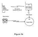
- Figures 3a, 3b and 3c are schematics depicting telephone communications involving wireless links and embodying the CELP vocoder technology.
- Figure 3a is a schematic of a communications link between a wireless mobile terminal 300 and a fixed (wired) terminal 330.
- Speech is compressed (encoded) by a vocoder located in mobile terminal 300 and sent via a wireless link (RF channel) to a base station 310 where it is decoded into PCM samples by the decode of a second vocoder.
- the signal is then directed, through various switches in the digital trunk of the telecommunication company network 315 to the central office 320 to which the fixed terminal 330 is physically connected.
- the digital signal is converted into analog format and routed to the terminal 330.
- speech is compressed and decompressed only once.
- Figure 3b is a schematic of a communications link between two wireless mobile terminals 340 and 380 with an embodiment of the invention including a two transcoders.
- Speech is compressed (encoded) by a vocoder located in mobile terminal A 340 and sent via a wireless link (RF channel A) to base station A 350 where it is decoded into PCM samples by the decoder of a second vocoder.
- the PCM samples are then sent via the telecommunication company network 360 to the second mobile terminal's base station B 370 where they are compressed (encoded) a second time by the second base station vocoder.
- the compressed signal is sent via a wireless link (RF channel B) to mobile terminal 380 where it is decoded a second time by the second mobile terminal's vocoder.
- Audible speech is then available at mobile terminal 380.
- Figure 3b also shows an embodiment of the invention including two transcoders 392 and 394 which will be described in detail below.
- Figure 3c is a schematic diagram of a communication link between two wireless mobile terminals with an embodiment of this invention including a cross transcoding node 390.
- the cross transcoding node will be described in detail below.
- tandemed vocoding This arrangement of vocoders is an example of what is called tandemed vocoding.
- Other examples of tandemed vocoding are situations where a wireless mobile terminal is communicating with a fixed wireless terminal, and when any type of wireless terminal is retrieving messages from a central voice-mail system that uses vocoders co compress speech before the data is stored. In such cases, speech is put through the compression and decompression algorithms of vocoders more than once. When vocoders are tandemed in such a manner, the quality of speech is usually degraded.
- a method called «bypass» was developed to eliminate the double decoding/encoding performed by vocoders in base stations 350 and 370.
- the basic idea behind this method is that base station A 350, knowing through signaling and control, that the vocoder in mobile terminal B 380 is identical with the vocoder in mobile terminal A 340, bypasses the vocoder, thus allowing the signal data frames to pass directly in the digital trunk 360 without being altered.
- base station 370 knowing that it receives compressed speech data frames, simply transmits the signal to the mobile terminal B 380 without any coding.
- the bypass method is fully described in the international application referred to earlier in this specification.
- the present invention provides a method and a system for reducing the signal degradation that occurs when vocoders are connected in tandem during a call.
- the system features mechanisms and protocols for the conversion of compressed speech data frames to an intermediate common representation during a connection, whether between two mobile terminals or between a mobile terminal and a fixed wireless terminal.
- Figure 4 shows a block diagram of a system constructed in accordance with the present invention to translate compressed speech signal from one format to another via a common format without the necessity of de-compressing the signal to a PCM type digitization technique.
- FIG. 5 is a block diagram showing a modular cross-transcoding system 510 having two transcoders having the same functional blocks, provided to implement the method in accordance with the invention.
- the transcoders are separate devices installed at the ends of the communication path to provide signal conversion functions. These signal conversion functions may be different depending on which communication standard the network is using.
- each transcoder may be associated with a base station of the network. Thus, a signal issued by one transcoder is transported over the telephone network toward the second transcoder where it is processed, as it will be described in detail later. Both transcoders have the same functional blocks. For simplicity, one transcoder will be described herein, and the description will apply to the other unit as well.
- the transcoder 510 includes a signaling and control block 520, an encoding block 530 and a decoding block 540.
- the main function of the signaling and control block 520 is to communicate (or attempt to communicate) through PCM bit stealing (in-band signaling) or direct communications from a central database (out-of band signaling) with the entity at the other end of the link to determine if:
- the decoding block 540 comprises a decoder 542, a pseudo-decoder 544 and a bypass section 546. Under the control of the signaling and control block 520, the decoding block 540 will perform one of the following tasks:
- the encoding block 530 comprises an encoder 532, a pseudo-encoder 534 and a bypass section 536. Under the control of the signaling and control block 520, the encoding block 530 will perform one of the following tasks:
- the signaling and control block 520 in the transcoder 510 is designed to transmit messages toward the transcoder 550 and also to receive messages from transcoder 550 such as to properly adjust the transcoder operations in accordance with the data that is being received from or sent toward the transcoder 550.
- the communication between the two transcoders is effected through a communication channel established between them.
- the communication channel can be either in-band or out of band.
- the process of bit stealing is used. This process consists of utilizing certain bits from certain speech samples to transmit signaling information. The location of the signaling bits and the bit robbing rate are selected to reduce the perceptual effect of the bit substitution, such that the audible signal at either one of the mobile terminals is not significantly affected.
- the receiving transcoder knows the location of the signaling bits in the speech samples and it is thus capable of decoding the message.
- the handshaking procedure between the transcoders 510 and 550 involves the exchange of different messages that enables one transcoder to identify the companion transcoder, so every unit can be set in a mode allowing to produce the best possible speech quality.
- the handshaking procedure involves the exchange of the following messages:
- a cross-transcoding node such as depicted in figure 6, is yet another embodiment of this invention. Note that for purposes of clarity only half of the total cross-transcoding node is shown. The other half of the cross-transcoding node is identical and provides communication capabilities in the opposite direction.
- the cross-transcoding node 600 acts as a centralized interface between speech codecs that are different. In essence, the transcoding node 600 can be viewed as two pairs of transcoders physically connected to one another, rather than being separated from one another as described in the earlier embodiment. Instead of using a separate signaling and control block for each transcoder, a single signaling and control stage 610 is used.
- the cross-transcoding node 600 also includes a decoding block 620, an encoding block 630 and a switch 640.
- the main function cf the signaling and control block 610 is to communicate (or attempt to communicate) with the entity at the other end of the link to determine if:
- Timing and synchronization information are used to control the decoding block 620 and the encoding block 630. Control information is used to select the correct position for switch 640 in order to route through the proper signal.
- Decoding block 620 comprises a decoder 622, a pseudo-decoder 624 and a bypass section 626.
- Encoding block 630 comprises a bypass section 632, a pseudo-encoder 634 and an encoder 636.
- the cross-transcoding node When interconnecting two vocoders, the cross-transcoding node will function as described below. Under the control of the signaling and control block 610, the decoding block 620 will perform one of the following tasks:
- the cross-transcoding node When connected to a wireline terminal, the cross-transcoding node will function as described below.
- a PCM signal When incoming, it is routed to the switch 640, the signaling and control block 610 selects switching to forward the signal to the encoder 636 where the signal is converted to compressed speech and, finally, the compressed speech will be sent to the external vocoder.
- the signal When a wireline terminal is on the receiving end of the communication and a compressed speech signal is incoming, the signal is routed to the decoder 622, where it is converted to PCM format , then, the signaling and control block selects switching to forward the signal to the wireline terminal.
- MT A uses a Veccor-Sum Enhanced Linear Prediction (VSELP) vocoder in the IS 54 wireless telephony communication standard.
- VSELP Veccor-Sum Enhanced Linear Prediction
- Figure 7a describes the frame format for IS 54.
- the signal is converted to a common format as per Figure 7b and at the receiving end, MT B uses an Enhanced Full-Rate Coder (EFRC) in the IS 641 standard.
- EFRC Enhanced Full-Rate Coder
- a speech signal is compressed (encoded) in the IS 54 standard by a VSELP vocoder located in MT A 340 and sent via a wireless link (RF channel A) to base station A 350 where it is transformed into the common format by the pseudo-decoder 544 in transcoder 510 (depicted in Figure 5).
- the common format data frames are then sent via the telecommunication company network 360 to transcoder 550 where they are transformed to compressed speech in the IS 641 standard by the pseudo-encoder 584.
- the compressed signal is sent via a wireless link (RF channel B) to MT 380 where it is decoded by the second MT's EFRC vocoder. Audible speech is then available at MT 380.
- the pseudo-decoder 544 receiving a data frame of speech in the IS 54 format as shown at Figure 7a, converts it as described below and also as illustrated by the flow chart of Figure 8.
- the pseudo-decoder 544 recomputes the 10 dimensional vector representing the LPC reflection coefficients for the 20 ms data frame using its own quantizer. It then uses the 10 dimensional vector to determine the 4 sets of interpolated LPC coefficient vectors for the 4 subframes.
- the interpolation method is the same as the one described earlier. This part of the common format data frame is ready and the pseudo-decoder 544 stores it for future retrieval.
- the pseudo-decoder 544 then reads, from the compressed format, the 4 lag values (pitch delay).
- the pseudo-decoder 544 stores them for future insertion into the common format.
- the pseudo-decoder 544 uses the codebook information, gain factors and pitch delays for the 4 subframes and the frame energy for the frame to create a synthetic excitation signal (4 times 40 samples) for the common format.
- the common format data frame is built by concatenating the excitation signal and the scored LPC filter coefficients and pitch delays. This data frame is sent to the pseudo-encoder 584 of the next base station. Note that on figure 7b, provisions have been made to reserve bits of information in the common format frame for energy and pitch prediction gain information. This information was not calculated in this particular example.
- the pseudo-encoder 584 receives the common format speech data frame and now needs to convert it to IS 641 compressed speech format in order for the EFRC at MT B to decode it properly.
- the pseudo-encoder 584 reads the LPC coefficients for the 4 subframes and discards the coefficients for the first three subframes keeping only the fourth subframe coefficients. Note that this is the LPC reflection coefficient vector computed for the whole frame.
- the first three vectors for the transformation in this specific example are not required since the EFRC vocoder at MT B will interpolate the first three subframe vectors according to the IS-641 interpolation scheme. All four vectors could be used though, for transformations involving other types of vocoders.
- the pseudo-encoder 584 requantizes the 4th subframe LPC reflection coefficients using its own quantizer. Before the pseudo-encoder presents the 10 LPC reflection coefficients to its quantizer, it needs to convert them into LP (linear prediction) coefficients first, then into Line Spectrum Pair (LSP) coefficients, and finally, into Line Spectral Frequencies (LSFT vector). The LSF vector is then quantized and converted to a quantized LSP vector. This quantized LSF vector is part of the IS 641 format and is stored as is. Then, the pseudo-encoder 584 transforms the quantized LSP vector into quantized LP coefficients and interpolates the LP coefficients for the first three subframes. This set of LP coefficient vectors will be used in the next step.
- LP Line Spectrum Pair
- LSFT vector Line Spectral Frequencies
- the pseudo-encoder 584 uses the common format excitation signal and passes each of the four 40 sample subframes through a synthesis filter, using the quantized and interpolated L? coefficients as tap coefficients, to re-create the speech signal. From the speech signal, the pseudo-encoder 584 computes (in the same manner as a regular EFRC encoder would) pitch lag, gain and excitation values (algebraic code for MT B codebook), by utilizing the previously computed 10 LSP coefficients. Finally, the IS 641 compressed speech format frame is built using the quantized pitch delay, gain and excitation values and the stored LSP vector. This speech data frame is sent to the EFRC decoder in MT B where it will be convert into a speech signal as it would normally.
- pitch delay information from the common format is not used in this example, but it can be used in other conversion. Instead, the pitch delay information was computed from the generated speech signal using known algorithms.
- the pseudo-decoder 534 converts the incoming compressed speech signal into a common format, that has a coefficients part and an excitation part. That common format is then used by the pseudo-encoder to recreate the compressed speech but in a format different from the format of the compressed speech entering the pseudo-decoder 544. More specifically, the pseudo-encoder 584 builds, from the coefficients part in the common format signal, the coefficients of the compressed speech signal to be output by the pseudo-encoder 584. On the basis of the common format signal, the speech signal is re-created and used to extract any excitation or other information, that in conjunction with the coefficients calculated for the compressed speech signal is used to represent the speech information.
- each pseudo-decoder will accept a compressed speech signal and issue a common format signal that in turn will be transformed by the pseudo-encoder into another compressed speech signal format.
- This feature enables the system to be very flexible, particularly when new vocoders are introduced. It suffices to design a pseudo-encoder and a pseudo-decoder that will provide the transformation between the new vocoder signal format and the common format and vice-versa. There is no necessity to alter the existing transcoders in any way since the common format used by the system remains the same.
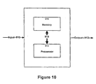
- the apparatus illustrated at Figure 10 can be used to implement the function of a pseudo-encoder 584 whose operation was detailed above in connection with Figure 9.
- the apparatus comprises an input signal line 910, a signal output line 912, a processor 914 and a memory 916.
- the memory 916 is used for storing instructions for the operation of the processor 914 and also for storing the data used by the processor 914 in executing those instructions.
- a bus 918 is provided for the exchange of information between the memory 916 and the processor 914.
- the instructions stored in the memory 916 allow the apparatus to operate according to the functional block diagram illustrated at figure 11.
- the apparatus includes a coefficients segment converter that, as described in connection with figure 9 converts through known mathematical manipulations the coefficients segment from the common format frame into the coefficients segment of the compressed audio signal frame, in this example in the IS 641 frame format.
- the apparatus also includes a synthesis filter that receives from the coefficients segment converter quantized LPC coefficients for the four sub frames.
- the synthesis filter also receives the excitation signal from the excitation segment of the common format frame in order to construct the audio signal. That signal is then input into an analysis-by-synthesis process that generates the excitation segment for the IS 641 frame format, by using as tap coefficients the quantized LSP vector output by the coefficients segment converter.
- Figure 12 illustrates the block diagram of the pseudo-decoder 544 illustrated at Figure 5.
- the apparatus includes two main functional blocks, namely a coefficients segment converter that receives the coefficients segment from the data frame in the IS 54 format and converts it into the coefficients segment of the common format data frame.
- the apparatus also includes an excitation segment converter that uses the elements of the excitation segment from the IS 54 data format to convert it into the excitation segment of the common format data frame.
- the approach in this design is to treat all segments of the data frame cf compressed audio signal to build the data frame of common format.
- the pseudo-encoder and the pseudo-decoder can be constructed by using one of the devices depicted at figures 11 and 12.
- the choice of either system will depend upon the particular format translation to be effected.
- the format of the compressed audio signal (either the source data frame or the destination data frame) is such that the coefficients segment and the excitation segment from the source data frame can be processed independently to effect the translation to the destination data frame, the apparatus depicted at figure 12 is probably best suited for the operation.
- the apparatus depicted at figure 11 should be employed.
- each transcoder can be built in accordance with systems that are presently known to those skilled in the art. More specifically, the encoder and the decoder can be constructed in accordance with the block diagrams of Figures 1 and 2.
Abstract
Description
- This invention relates to a method and to an apparatus for transmitting digitized voice signals, in a communications environment that can be of a wireless nature. More specifically, it relates to a method and to an apparatus for improving the quality of an audio signal that has been compressed or encoded with a digital signal processing technique, when the signal is transmitted from one terminal to another of a communication network.
- In recent years, the telecommunications industry has witnessed the proliferation of a variety of digital vocoders in order to meet bandwidth demands of different wireline and wireless communication systems. The name «vocoder» stems from the fact that its applications are specific to the encoding and decoding of voice signals primarily. Vocoders are usually integrated in mobile telephones and the base stations of the communication network. They provide speech compression of a digitized voice signal as well as the reverse transformation. Typically, a voice signal is digitized through one of many quantization techniques. Examples of these techniques are Pulse Amplitude Modulation (PAM), Pulse Code Modulation (PCM) and Delta Modulation. For the purposes of this description we will refer to PCM as the input format for the vocoder. Thus a vocoder includes an encoder stage that will accept as input a digitized voice signal and output a compressed signal, a possible compression ratio being 8:1. As for the reverse transformation the vocoder is provided with a decoder stage that will accept the compressed speech signal and output a digitized signal, such as PCM samples.
- The main advantage of compressing speech is that it uses less of the limited available channel bandwidth for transmission. The main disadvantage is loss of speech quality.
- Most modern low bit-rate vocoders are based on the linear prediction model that separates the speech signal into a set of linear prediction coefficients, a residual signal and various other parameters. Generally, the speech can be reconstructed with good quality from these components. However, degradations are introduced when speech is subjected to multiple instances of vocoders.
- The rapid growth in the diversity of networks and the number of users of such networks is increasing the number of instances where two vocoders are placed in tandem to serve a single connection. In such a case, a first encoder is used to compress the speech of the first mobile user. The compressed speech is transmitted to a base station serving the local mobile where it is decompressed (converted to PCM format samples). The resulting PCM samples arrive at the base station serving the second mobile terminal, over the digital trunk of the telephone network, where a second encoder is used to compress the input signal for transmission to the second mobile terminal. A speech decoder at the second mobile terminal decompresses the received compressed speech data to synthesize the original speech signal from the first mobile terminal. A specific example of such a case may involve a call made from a wireless terminal operating according to the North American Time Division Multiplexing Access (TDMA) system to a European standard Global System for Mobile (GSM) mobile phone.
- In an attempt to eliminate the condition of vocoder tandeming, a method called «bypass» has been proposed in the past. The basic idea behind this approach is the provision of a digital signal processor including a vocoder and a bypass mechanism that is invoked when the incoming signal is in a format compatible with the vocoder. In use, the digital signal processor associated with the first base station that receives the RF signal from a first mobile terminal determines, through signaling and control that an identical digital signal processor exists at the second base station associated with the mobile terminal at which the call is directed. The digital signal processor associated with the first base station rather than converting the compressed speech signals into PCM samples invokes the bypass mechanism and outputs the compressed speech in the transport network. The compressed speech signal, when arriving at the digital signal processor associated with the second base station is routed such as to bypass the local vocoder. Decompression of the signal occurs only at the second mobile terminal.
- This solution is only valid, though, for identical vocoders. With the rapid expansion of networks, the diversity of vocoders is quickly increasing. The bypass solution is therefore useful only for a small portion of connections involving tandem vocoding.
- EP 0 138 073 describes a converter for interface adaptation between LPC and channel vocoders for the transmission of digitised speech signals via digital narrow band communication systems. The converter includes two partial interfaces arranged in parallel to one another. One of the partial interfaces converts LPC coded and speech signal sections to be transmitted into coding for the channel vocoder. The other partial interface converts the coding for the channel vocoder into coding in the LPC method. This method makes use of code books to map the quantized LPC coded parameters to corresponding channel vocoder parameters and vice versa.
- Thus, there exists a need in the industry for devices capable of improving the voice quality during connections that may include incompatible tandemed vocoders.
- An object of the invention is to provide an apparatus for processing audio signals that may reduce the signal degradation occurring when the signal is exchanged between two vocoders in a communication network.
- Another object of the invention is to provide a method for reducing audio signal degradation when the signal is transmitted from one vocoder to another vocoder in a communication network.
- According to the invention, there is provided an apparatus for communicating a data frame of compressed audio information between incompatible vocoders, said apparatus including:
- a first transcoder including a first input and a first output, said first transcoder being responsive to a frame of compressed audio data of a first format applied to said input to generate at said output a frame of compressed audio data of an intermediate format, the frame of first format having a coefficient segment and an excitation segment, the frame of the intermediate format having a coefficient segment and an excitation segment;
- a second transcoder including a second input and a second output, said second input being linked to said first output to receive the frame of compressed audio data of the intermediate format, said second transcoder being responsive to a frame of compressed audio data of a intermediate format applied to said second input to generate at said second output a frame of compressed audio data of a second format, the frame of second format having a coefficient segment and an excitation segment.
- This system is advantageous particularly when the telephone network is provided with a variety of non-identical vocoders. To enable the exchange of speech signals from one vocoder to another vocoder, irrespective of whether they are identical or not, it suffices to convert the compressed audio signal issued by the local vocoder to the common format that can be processed by the pseudo-encoder of the remote vocoder. The common format can be defined as a compressed audio signal of an intermediate representation that is intended to convey important parametric information transmitted by the pseudo-decoder of the local vocoder directly to the pseudo-encoder of the remote vocoder. Such parametric information includes a coefficient segment and parameters describing an excitation segment of the speech signal being transmitted. One important element of the common format representation is that it retains the basic frame structure of the audio signal as it is encoded by one of the vocoders in the network that may be linked to one another during a given call. More specifically, the common format frame is comprised of a coefficients segment and an excitation segment, that will be defined below. It is important to note, however, that no attempt has been made to reduce the audio signal to PCM samples or to an equivalent representation, as a common format structure. This is not desirable because the transformation of the compressed signal to PCM and then the conversion of the PCM samples to compressed form introduces significant degradations in the signal quality that should be avoided as much as possible. The present inventors have discovered that by designing a common format configuration that retains the basic structure of audio signals as encoded by a vocoder, those degradations are significantly reduced.
- In this specification, the term "coefficient segment" is intended to refer to any set of coefficients that uniquely defines a filter function which models the human vocal tract. It also refers to any type of information format from which the coefficients may indirectly be extracted. In conventional vocoders, several different types of coefficients are known, including reflection coefficients, arcsines of the reflection coefficients, line spectrum pairs, log area ratios, among others. These different types of coefficients are usually related by mathematical transformations and have different properties that suit them to different applications. Thus, the term "coefficient segment" is intended to encompass any of these types of coefficients.
- The "excitation segment" can be defined as information that needs to be combined with the coefficients segment in order to provide a complete representation of the audio signal. It also refers to any type of information format from which the excitation may indirectly be extracted. The excitation segment complements the coefficients segment when synthesizing the signal to obtain a signal in a non-compressed form such as in PCM sample representations. Such excitation segment may include parametric information describing the periodicity of the speech signal, an excitation signal as computed by the pseudo-decoder, speech framing control information to ensure synchronous framing in the pseudo-encoder associated with the remote vocoder, pitch periods, pitch lags, gains and relative gains, among others. The coefficient segment and the excitation segment can be represented in various ways in the signal transmitted through the network of the telephone company. One possibility is to transmit the information as such, in other words a sequence of bits that represents the values of the parameters to be communicated. Another possibility is to transmit a list of indices that do not convey by themselves the parameters of the common format signal, but simply constitute entries in a database or codebook allowing the pseudo-encoder to look-up this database and extract on the basis of the various indices received the pertinent information to construct the common format signal.
- The expression "first format", "second format" or "third format" when used to describe the audio signal in compressed form, either in the common format representation or in the format of a given vocoder, refers to signals that are, generally speaking, not compatible, although they share a common basic structure, in other words they are divided into coefficients segment and excitation segment. Thus, a vocoder capable of converting a signal under the first format will not, generally speaking, be capable of processing a signal expressed under any other format than the first format.
- In a preferred embodiment, the transformation of audio signal in the compressed form to the common format is effected in two steps. The first step is to process the coefficients segment in the compressed audio signal data frame to generate the coefficients segment of the common format. Generally speaking, the transformation, from one type of coefficients to another, is effected by well-known mathematical algorithms. Depending upon the kind of vocoder associated with the pseudo-decoder, this transformation may be effected simply by re-quantizing the coefficients from the compressed audio signal data frame into new values that would constitute the coefficients of the common format data frame. In the next step, the excitation segment of the common format data frame is obtained by processing the frame energy, gain values, lag values and codebook information (as would the decoder portion of a vocoder normally) and quantize the excitation signal before forming a common format data frame.
- The transformation from the common format data frame to compressed audio signal by a pseudo-encoder is effected in a similar manner as described earlier. The coefficients segment of the common format data frame is processed first to generate the coefficients segment of the compressed audio signal data frame. The excitation segment of the compressed audio signal data frame is obtained by first synthesizing a speech signal by passing the common format excitation segment through a filter for which the coefficients were also obtained from the common format. This signal is applied to the encoder portion of the vocoder as it would ordinarily.
- Another possibility for obtaining the excitation segment in one format from a data frame in another format, without synthesizing an audio signal and then effecting an analysis, is to re-compute the excitation segment solely from data available in the excitation segment in the source data frame. The choice of this method or the method described above will depend upon the intended application or the type of conversion that is being required. More specifically, certain formats of compressed audio signals can be easily converted to the common frame by re-computing the segments of each frame independently from one another. In other instances, however, it is more practical to use an analysis-by-synthesis approach to obtain the excitation segment.
- The invention also provides a method of transmission of a data frame between incompatible vocoders, the data frame being representative of audio information in digitized and compressed form, the data frame including a coefficient segment and an excitation segment, the data frame being in a first format, said method comprising the steps of:
- processing at a first site the data frame in the first format to generate a data frame of an intermediate format, the data frame of the intermediate format including a coefficient segment and an excitation segment;
- transmitting the data frame of a intermediate format to a second site remote from said first site;
- processing at said second site the data frame of the intermediate format to generate a data frame of a second format, the data frame of a second format including a coefficient segment and an excitation segment.
-
- Figure 1 is a block diagram of the encoder stage of a CELP vocoder;
- Figure 2 is a bloc diagram of the decoder stage of an CELP vocoder;
- Figure 3a is a schematic diagram of a communication link between a wireless mobile terminal and a fixed (wired) terminal;
- Figure 3b is a schematic diagram of a communication link between two wireless mobile terminals with an embodiment of this invention including two transcoders;
- Figure 3c is a schematic diagram of a communication link between two wireless mobile terminals with an embodiment of this invention including a cross transcoding node;
- Figure 4 is a block diagram of a system constructed in accordance with the present invention to translate compressed speech signal from one format to another via a common format without the necessity of de-compressing the signal to a PCM type digitization technique;
- Figure 5 is a more derailed block diagram of the system depicted in figure 4;
- Figure 6 is a block diagram of a cross-transcoding node, that constitutes a variant of the system depicted in figure 5;
- Figure 7a illustrates a data frame in a
IS 54 format; - Figure 7b illustrates a data frame of the common format produced by the transcoder depicted in Figure 5 or the transcoder depicted in Figure 6;
- Figure 7c illustrates a data frame in the
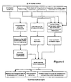
IS 641 format; - Figure 8 is a flowchart of the operation to convert compressed speech data frame in the
IS 54 format to the common format; - Figure 9 is a flowchart of the operation to convert a data frame in the common format to the compressed speech format IS 641;
- Figure 10 is a block diagram of an apparatus for implementing the functionality of a pseudo-encoder of the type depicted in Figure 5;
- Figure 11 is functional block diagram of the apparatus shown in Figure 10; and
- Figure 12 is a functional block diagram of a variant of the apparatus shown in Figure 10.
- The following is a description of the Linear Predictive Coding (LPC) vocoder technology presently used in wireless telecommunications. One application of specific interest is the wireless transmission of a signal between a mobile terminal and a fixed base station. Another application is the transmission of speech over the internet communication network where different vocoders may be used in separate parts of the wireline network.
- In communications applications where channel bandwidth is at a premium, it is essential to use the smallest possible portion of a transmission channel. A common solution is to quantize and compress the voice signal uttered by a user before it is transmitted.
- Typically, the voice signal is first digitized by means of one of many quantization techniques. Examples of these techniques are Pulse Amplitude Modulation (PAM), Pulse Code Modulation (PCM) and Delta Modulation, PCM being perhaps the most popular. Basically, in PCM, samples of an analog signal are taken at a specified rate (8 kHz is common) and quantized into discrete values for representation in digital format.
- Codecs, including an encoding and a decoding stage are then used to compress (and decompress) the digital signals at the source and reception point, respectively, in order to optimize the use of transmission channels. Codecs used specifically fcr voice signals are dubbed «vocoders» (for voice coders). By encoding only the necessary characteristics of a speech signal, fewer bits need to be transmitted than what is required to reproduce the original waveform in a manner that will not significantly degrade the speech quality. With fewer bits required, lower bit rate transmission can be achieved.
- At present, most low bit-rate vocoders are of the Linear Predictive Coding (LPC) family that extracts pertinent speech features from a waveform in the time domain. Vocoders have two main components: an encoder and a decoder. The encoder part processes the digitized speech signal to compress it, while the decoder part expands compressed speech into a digitized audio signal.
- An LPC-type vocoder uses a weighted sum of the past p samples of speech (s n-k ) to estimate the present sample (s n ). The number p determines the order of the model. The higher the order is, the better the speech quality. Typical model orders range from 10 to 15. It follows that an equation for a speech sample can be written as:

where
a k is a coefficient which determines the contribution of the last S n-k sample, and
e n is the error signal for the present sample. - Using the z-transform of S n and e n , and defining a prediction filter we obtain:

where
- The filter

- Figure 1 is a block diagram of the encoder portion of a generic model for a CELP vocoder. As can be seen from this figure, the input to the vocal tract analysis block 100 of the encoder part are PCM samples and the output consists of an LPC filter Coefficrent segment and an excitation segment consisting of several parameters representing the prediction error signal (also called residual). The output is forwarded to a telecommunication channel.
- The number of L?C filter coefficients in the coefficient segment is determined by the order p of the model. Examples of excitation segment parameters are: nature of excitation (voiced or unvoiced), pitch period (for voiced excitation), gain factors, energy, pitch prediction gain, etc. Code Excited Linear Prediction. (CELP) vocoders are the most common type of vocoder used in telephony presently. Instead of sending the excitation parameters, CELP vocoders send index information which points to a set of vectors in an adaptive and stochastic code book. That is, for each speech signal, the encoder searches through its code book for the one that gives the best perceptual match to the sound when used as an excitation to the LPC synthesis filter.
- A speech frame including this information is recalculated every T seconds. A common value for T is 20 ms. A 20 ms compressed speech frame represents 160 PCM samples taken at 8 kHz.
- Figure 2 is a block diagram of the decoder portion of a generic model for a CELP vocoder. The compressed speech frame is received from
telecommunication channel 210 and fed to anLPC synthesis filter 220. TheLPC synthesis filter 220 uses the LPC filter coefficient segment and the excitation segment to produce and output speech signal usually in a PCM sample form. - A technique called interpolation is used as an enhancement to vocoders. It consists of the subdivision of the 20 ms speech frames into sub-frames of 5 ms and the interpolation of their predictor coefficients. This techniques is useful to avcid undesirable «popping» or «clicking» noises in the generated speech signal, that are usually the result of rapid changes in the predictor coefficients from one signal frame to the other. More specifically, each signal frame is divided into four sub-frames, that can be designated as sub-frame (1), sub-frame (2), sub-frame (3) and sub-frame (4), for reference purposes. The predictor coefficients used for speech signal generation over the first sub-frame, namely sub-frame (1), is a combination of the predictor coefficients for the previous frame with the coefficients for the current frame, in a ratio 75%/25%. For sub-frame (2), this ratio changes to 50%/50%, for sub-frame (3), the ratio reaches 25%/75%, while for the last sub-frame (sub-frame (4), the ratio is 0%/100%, in other words only the coefficients from the current frame are used.
- Figures 3a, 3b and 3c are schematics depicting telephone communications involving wireless links and embodying the CELP vocoder technology.
- Figure 3a is a schematic of a communications link between a wireless
mobile terminal 300 and a fixed (wired)terminal 330. Speech is compressed (encoded) by a vocoder located inmobile terminal 300 and sent via a wireless link (RF channel) to abase station 310 where it is decoded into PCM samples by the decode of a second vocoder. The signal is then directed, through various switches in the digital trunk of thetelecommunication company network 315 to thecentral office 320 to which the fixedterminal 330 is physically connected. At the central office, the digital signal is converted into analog format and routed to the terminal 330. In such a scenario, speech is compressed and decompressed only once. - Figure 3b is a schematic of a communications link between two wireless
mobile terminals mobile terminal A 340 and sent via a wireless link (RF channel A) tobase station A 350 where it is decoded into PCM samples by the decoder of a second vocoder. The PCM samples are then sent via thetelecommunication company network 360 to the second mobile terminal'sbase station B 370 where they are compressed (encoded) a second time by the second base station vocoder. The compressed signal is sent via a wireless link (RF channel B) tomobile terminal 380 where it is decoded a second time by the second mobile terminal's vocoder. Audible speech is then available atmobile terminal 380. Figure 3b also shows an embodiment of the invention including twotranscoders - Figure 3c is a schematic diagram of a communication link between two wireless mobile terminals with an embodiment of this invention including a
cross transcoding node 390. The cross transcoding node will be described in detail below. - This arrangement of vocoders is an example of what is called tandemed vocoding. Other examples of tandemed vocoding are situations where a wireless mobile terminal is communicating with a fixed wireless terminal, and when any type of wireless terminal is retrieving messages from a central voice-mail system that uses vocoders co compress speech before the data is stored. In such cases, speech is put through the compression and decompression algorithms of vocoders more than once. When vocoders are tandemed in such a manner, the quality of speech is usually degraded.
- To compensate for degradations of the speech signal caused by tandemed connections of low bit-rate codecs (vocoders), a method called «bypass» was developed to eliminate the double decoding/encoding performed by vocoders in
base stations base station A 350, knowing through signaling and control, that the vocoder inmobile terminal B 380 is identical with the vocoder inmobile terminal A 340, bypasses the vocoder, thus allowing the signal data frames to pass directly in thedigital trunk 360 without being altered. Similarly,base station 370 knowing that it receives compressed speech data frames, simply transmits the signal to themobile terminal B 380 without any coding. The bypass method is fully described in the international application referred to earlier in this specification. - However, this solution is only valid for identical vocoders. With the rapid expansion of networks, the diversity of vocoders is quickly increasing. The bypass solution is therefore useful only for a small portion of connections involving tandem vocoding.
- The present invention provides a method and a system for reducing the signal degradation that occurs when vocoders are connected in tandem during a call. The system features mechanisms and protocols for the conversion of compressed speech data frames to an intermediate common representation during a connection, whether between two mobile terminals or between a mobile terminal and a fixed wireless terminal.
- Figure 4 shows a block diagram of a system constructed in accordance with the present invention to translate compressed speech signal from one format to another via a common format without the necessity of de-compressing the signal to a PCM type digitization technique.
- One specific embodiment of this system is depicted in figure 5 that is a block diagram showing a modular
cross-transcoding system 510 having two transcoders having the same functional blocks, provided to implement the method in accordance with the invention. The transcoders are separate devices installed at the ends of the communication path to provide signal conversion functions. These signal conversion functions may be different depending on which communication standard the network is using. In a typical application, each transcoder may be associated with a base station of the network. Thus, a signal issued by one transcoder is transported over the telephone network toward the second transcoder where it is processed, as it will be described in detail later. Both transcoders have the same functional blocks. For simplicity, one transcoder will be described herein, and the description will apply to the other unit as well. - The
transcoder 510 includes a signaling and control block 520, anencoding block 530 and adecoding block 540. The main function of the signaling and control block 520 is to communicate (or attempt to communicate) through PCM bit stealing (in-band signaling) or direct communications from a central database (out-of band signaling) with the entity at the other end of the link to determine if: - a) the connection terminates on an identical LPC-type vocoder,
- b) the connection terminates on a different LPC-type vocoder,
- c) the connection terminates on an entity not covered by a) or b) above (i.e. vocoder of another family type, new type of LPC vocoder, wireline terminal, etc.)
- The
decoding block 540 comprises adecoder 542, a pseudo-decoder 544 and abypass section 546. Under the control of the signaling and control block 520, thedecoding block 540 will perform one of the following tasks: - a) when the connection terminates on an identical LPC-type vocoder, send the compressed speech signal, from mobile terminal A, through the
bypass section 546 which will passthrough the compressed speech data, possibly after reformatting, for transmission to thebypass section 586 oftranscoder 550 toward mobile terminal B, - b) when the connection terminates on a different LPC-type vocoder for which a transcoding module is available, apply the pseudo-decoder 544 to convert compressed speech data, from mobile terminal A, to a common-format signal for transmission to the
pseudo-encoder 584 oftranscoder 550, or - c) when the connection terminates on a entity not covered by a) or b) above (i.e. vocoder of another family type, new type of LPC vocoder, wireline terminal, etc.), apply the
speech decoder 542 to convert compressed speech data, from mobile terminal A, to PCM samples for transmission to theencoder 582cf transcoder 550 or thecentral office 590. - The
encoding block 530 comprises anencoder 532, a pseudo-encoder 534 and abypass section 536. Under the control of the signaling and control block 520, theencoding block 530 will perform one of the following tasks: - a) when the connection source has an identical LPC-type vocoder, send the speech signal, received from the
bypass section 576 oftranscoder 550, to thebypass section 536 which will passthrough compressed speech data, possibly after reformatting, for transmission to mobile terminal A to which thetranscoder 510 is connected; - b) when the connection source has a different LPC-type vocoder for which a transcoding module is available, invoke the pseudo-encoder 534 to convert a common-format signal, received from the pseude-
decoder section 574 oftranscoder 550, to compressed speech data and forward the signal to mobile terminal A, - c) when the connection terminates on a entity not covered by a) or b) above (i.e. vocoder of another family type, new type of LPC vocoder, wireline terminal, etc.), apply the
speech encoder 532 to convert PCM format samples, received from thedecoder 572 oftranscoder 550 or thecentral office 590, to compressed speech data and forward the compressed speech data to mobile terminal A. - The signaling and control block 520 in the
transcoder 510 is designed to transmit messages toward thetranscoder 550 and also to receive messages fromtranscoder 550 such as to properly adjust the transcoder operations in accordance with the data that is being received from or sent toward thetranscoder 550. The communication between the two transcoders is effected through a communication channel established between them. The communication channel can be either in-band or out of band. - During PCM transmission, the process of bit stealing is used. This process consists of utilizing certain bits from certain speech samples to transmit signaling information. The location of the signaling bits and the bit robbing rate are selected to reduce the perceptual effect of the bit substitution, such that the audible signal at either one of the mobile terminals is not significantly affected. The receiving transcoder knows the location of the signaling bits in the speech samples and it is thus capable of decoding the message.
- The handshaking procedure between the
transcoders - a) the transmitter of the signaling and control block 520 embeds an identifier in the PCM speech signal issued by the
transcoder 510. This identifier enables any remote transcoder to precisely determine the type of vocoder connected to the originating transcoder, namely thetranscoder 510. The identification is effected by a database seeking operation, as it will be described hereafter. - b) the signaling and control block 560 examines the data frames received by the
transcoder 550 and extracts any inband signaling information. This is effected by observing the bit values at the predetermined locations in the data frame. If the message is a transcoder identifier, a database (not shown in the drawings) is consulted to determine the type of vocoder connected to the transcoder issuing the message. Depending upon the contents of the message, the following possibilities arise:- 1) the default mode for the encoding blocks 530 and 580, and the decoding blocks 540 and 570 is such that the
encoders decoders pseudo-encoders pseudo-decoders bypass sections - 2) if the signaling and
control block 510, has identified the presence of a remote transcoder, the identifier of the transcoder is verified in the local database to determine the type of transcoder that is sending the messages. If:- i) the transcoder is identical, in other words the vocoder connected to the remote transcoder operates according to the same frame format or standard as the vocoder linked to the
transcoder 510, the signal and control block 520 causes the decoding block to enable thebypass stage 546, while disabling thedecoder 542 and the pseudo-decoder 544. Thus, any compressed speech data received from the remote transcoder will be directed to mobile terminal A without decoding. This mode of operation is the one that allows achieving the best possible voice quality since no vocoder tandeming occurs. The signal and control block 520 will also switch theencoding block 530 to a state in which thebypass 536 is active, while theencoder 532 and the pseudo-encoder 534 are inactive. Thus, compressed speech data received from mobile terminal A will be passed through thetranscoder 510 without any decoding. It should be observed that the decision to switch theencoding block 530 to the bypass mode is based on the assumption that the signaling and control block 560 of theremote transcoder 550 has received the identifier of thetranscoder 510 and has set thedecoding block 570 and theencoding block 530 to the bypass mode also. In this case, full duplex connection is established between the transcoders that exchange compressed speech signals. - ii) the transcoder is different, that is the remote transcoder indicates that the vocoder associated with mobile terminal B is of a different LPC-type, then the signaling and control block 520 enables the
decoding block 540 to activate the pseudo-decoder 544, while disabling thedecoder 542 and thebypass 546. In this mode of operation, the signaling and control block 520 expects to receive speech signals encoded in a common format that the pseudo-decoder 544 will transform into the format of the vocoder associated with the mobile station A. Also, the signaling and control block 520 will switch theencoding block 530 to a mode in which the pseudo-encoder 534 is active while theencoder 532 and thebypass 536 are inactive. Thus, the data issued by thetranscoder 510 is in a common format that the pseudo-encoder 584 will encode in the format of the vocoder associated with the mobile terminal B.
- i) the transcoder is identical, in other words the vocoder connected to the remote transcoder operates according to the same frame format or standard as the vocoder linked to the
- 1) the default mode for the encoding blocks 530 and 580, and the decoding blocks 540 and 570 is such that the
- A cross-transcoding node, such as depicted in figure 6, is yet another embodiment of this invention. Note that for purposes of clarity only half of the total cross-transcoding node is shown. The other half of the cross-transcoding node is identical and provides communication capabilities in the opposite direction. The
cross-transcoding node 600 acts as a centralized interface between speech codecs that are different. In essence, thetranscoding node 600 can be viewed as two pairs of transcoders physically connected to one another, rather than being separated from one another as described in the earlier embodiment. Instead of using a separate signaling and control block for each transcoder, a single signaling andcontrol stage 610 is used. Thecross-transcoding node 600 also includes adecoding block 620, anencoding block 630 and aswitch 640. - The main function cf the signaling and control block 610 is to communicate (or attempt to communicate) with the entity at the other end of the link to determine if:
- a) the connection terminates on an identical LPC-type vocoder,
- b) the connection terminates on a different LPC-type vocoder for which a transcoding module is available,
- c) the connection terminates on a entity not covered by a) or b) above (i.e. vocoder of another family type, new type of LPC vocoder, wireline terminal, etc.).
- Timing and synchronization information are used to control the
decoding block 620 and theencoding block 630. Control information is used to select the correct position forswitch 640 in order to route through the proper signal. - Decoding block 620 comprises a
decoder 622, a pseudo-decoder 624 and abypass section 626.Encoding block 630 comprises abypass section 632, a pseudo-encoder 634 and anencoder 636. - When interconnecting two vocoders, the cross-transcoding node will function as described below. Under the control of the signaling and
control block 610, thedecoding block 620 will perform one of the following tasks: - a) when the connection terminates on an identical LPC-type vocoder, send the compressed speech signal to the
bypass section 626 which will passthrough the speech data via thebypass section 632, possibly after reformatting, for transmission to the identical LPC-type vocoder, - b) when the connection terminates on a different LPC-type vocoder for which a transcoding module is available, apply the pseudo-decoder 624 to convert compressed speech data to a common-format signal, then route the signal to the pseudo-encoder 634 to convert the common format back to a compressed signal and finally, send the compressed speech signal to the different LPC-type vocoder or
- c) when the connection terminates on a entity not covered by a) or b) above (i.e. vocoder of another family type, new type of LPC vocoder, wireline terminal, etc.), apply the
speech decoder 622 to convert compressed speech data to PCM samples, then route the signal to theencoder 636 to convert the PCM samples back to a compressed speech signal and finally, send the compressed speech signal to the end entity. - When connected to a wireline terminal, the cross-transcoding node will function as described below. When a PCM signal is incoming, it is routed to the
switch 640, the signaling and control block 610 selects switching to forward the signal to theencoder 636 where the signal is converted to compressed speech and, finally, the compressed speech will be sent to the external vocoder. When a wireline terminal is on the receiving end of the communication and a compressed speech signal is incoming, the signal is routed to thedecoder 622, where it is converted to PCM format , then, the signaling and control block selects switching to forward the signal to the wireline terminal. - The following description will now provide a specific example as to how the pseudo-encoder units effect the transformation from a compressed signal to a common format signal, as well as the reverse transformation, namely conversion from the common format to a compressed signal. More particularly, consider the situation where a speech signal is transformed when it is sent from mobile terminal (MT) A 340 to
MT B 380. In this example, MT A uses a Veccor-Sum Enhanced Linear Prediction (VSELP) vocoder in theIS 54 wireless telephony communication standard. Figure 7a describes the frame format for IS 54. The signal is converted to a common format as per Figure 7b and at the receiving end, MT B uses an Enhanced Full-Rate Coder (EFRC) in theIS 641 standard. Figure 7c illustrates the frame format forIS 641. - Referring to figures 3b and 5, for the transformation in this example, a speech signal is compressed (encoded) in the
IS 54 standard by a VSELP vocoder located inMT A 340 and sent via a wireless link (RF channel A) tobase station A 350 where it is transformed into the common format by the pseudo-decoder 544 in transcoder 510 (depicted in Figure 5). The common format data frames are then sent via thetelecommunication company network 360 to transcoder 550 where they are transformed to compressed speech in theIS 641 standard by the pseudo-encoder 584. The compressed signal is sent via a wireless link (RF channel B) toMT 380 where it is decoded by the second MT's EFRC vocoder. Audible speech is then available atMT 380. - The pseudo-decoder 544, receiving a data frame of speech in the
IS 54 format as shown at Figure 7a, converts it as described below and also as illustrated by the flow chart of Figure 8. The pseudo-decoder 544 recomputes the 10 dimensional vector representing the LPC reflection coefficients for the 20 ms data frame using its own quantizer. It then uses the 10 dimensional vector to determine the 4 sets of interpolated LPC coefficient vectors for the 4 subframes. The interpolation method is the same as the one described earlier. This part of the common format data frame is ready and the pseudo-decoder 544 stores it for future retrieval. The pseudo-decoder 544 then reads, from the compressed format, the 4 lag values (pitch delay). The pseudo-decoder 544 stores them for future insertion into the common format. The pseudo-decoder 544 then uses the codebook information, gain factors and pitch delays for the 4 subframes and the frame energy for the frame to create a synthetic excitation signal (4times 40 samples) for the common format. Finally, the common format data frame is built by concatenating the excitation signal and the scored LPC filter coefficients and pitch delays. This data frame is sent to thepseudo-encoder 584 of the next base station. Note that on figure 7b, provisions have been made to reserve bits of information in the common format frame for energy and pitch prediction gain information. This information was not calculated in this particular example. - As shown in Figure 9 the pseudo-encoder 584 receives the common format speech data frame and now needs to convert it to IS 641 compressed speech format in order for the EFRC at MT B to decode it properly. The pseudo-encoder 584 reads the LPC coefficients for the 4 subframes and discards the coefficients for the first three subframes keeping only the fourth subframe coefficients. Note that this is the LPC reflection coefficient vector computed for the whole frame. The first three vectors for the transformation in this specific example are not required since the EFRC vocoder at MT B will interpolate the first three subframe vectors according to the IS-641 interpolation scheme. All four vectors could be used though, for transformations involving other types of vocoders. At this point, the pseudo-encoder 584 requantizes the 4th subframe LPC reflection coefficients using its own quantizer. Before the pseudo-encoder presents the 10 LPC reflection coefficients to its quantizer, it needs to convert them into LP (linear prediction) coefficients first, then into Line Spectrum Pair (LSP) coefficients, and finally, into Line Spectral Frequencies (LSFT vector). The LSF vector is then quantized and converted to a quantized LSP vector. This quantized LSF vector is part of the
IS 641 format and is stored as is. Then, the pseudo-encoder 584 transforms the quantized LSP vector into quantized LP coefficients and interpolates the LP coefficients for the first three subframes. This set of LP coefficient vectors will be used in the next step. - The pseudo-encoder 584 uses the common format excitation signal and passes each of the four 40 sample subframes through a synthesis filter, using the quantized and interpolated L? coefficients as tap coefficients, to re-create the speech signal. From the speech signal, the pseudo-encoder 584 computes (in the same manner as a regular EFRC encoder would) pitch lag, gain and excitation values (algebraic code for MT B codebook), by utilizing the previously computed 10 LSP coefficients. Finally, the
IS 641 compressed speech format frame is built using the quantized pitch delay, gain and excitation values and the stored LSP vector. This speech data frame is sent to the EFRC decoder in MT B where it will be convert into a speech signal as it would normally. - Note that the pitch delay information from the common format is not used in this example, but it can be used in other conversion. Instead, the pitch delay information was computed from the generated speech signal using known algorithms.
- In summary, the pseudo-decoder 534 converts the incoming compressed speech signal into a common format, that has a coefficients part and an excitation part. That common format is then used by the pseudo-encoder to recreate the compressed speech but in a format different from the format of the compressed speech entering the pseudo-decoder 544. More specifically, the pseudo-encoder 584 builds, from the coefficients part in the common format signal, the coefficients of the compressed speech signal to be output by the pseudo-encoder 584. On the basis of the common format signal, the speech signal is re-created and used to extract any excitation or other information, that in conjunction with the coefficients calculated for the compressed speech signal is used to represent the speech information.
- It will be noted that the pseudo-encoder and the pseudo-decoder of the
transcoder 510 are designed in accordance with the type of vocoder wich which it will interact . The common element is that each pseudo-decoder will accept a compressed speech signal and issue a common format signal that in turn will be transformed by the pseudo-encoder into another compressed speech signal format. This feature enables the system to be very flexible, particularly when new vocoders are introduced. It suffices to design a pseudo-encoder and a pseudo-decoder that will provide the transformation between the new vocoder signal format and the common format and vice-versa. There is no necessity to alter the existing transcoders in any way since the common format used by the system remains the same. - From a structural point of view, the apparatus illustrated at Figure 10 can be used to implement the function of a pseudo-encoder 584 whose operation was detailed above in connection with Figure 9. The apparatus comprises an
input signal line 910, a signal output line 912, aprocessor 914 and amemory 916. Thememory 916 is used for storing instructions for the operation of theprocessor 914 and also for storing the data used by theprocessor 914 in executing those instructions. Abus 918 is provided for the exchange of information between thememory 916 and theprocessor 914. - The instructions stored in the
memory 916 allow the apparatus to operate according to the functional block diagram illustrated at figure 11. The apparatus includes a coefficients segment converter that, as described in connection with figure 9 converts through known mathematical manipulations the coefficients segment from the common format frame into the coefficients segment of the compressed audio signal frame, in this example in theIS 641 frame format. The apparatus also includes a synthesis filter that receives from the coefficients segment converter quantized LPC coefficients for the four sub frames. The synthesis filter also receives the excitation signal from the excitation segment of the common format frame in order to construct the audio signal. That signal is then input into an analysis-by-synthesis process that generates the excitation segment for theIS 641 frame format, by using as tap coefficients the quantized LSP vector output by the coefficients segment converter. - Figure 12 illustrates the block diagram of the pseudo-decoder 544 illustrated at Figure 5. The apparatus includes two main functional blocks, namely a coefficients segment converter that receives the coefficients segment from the data frame in the
IS 54 format and converts it into the coefficients segment of the common format data frame. The apparatus also includes an excitation segment converter that uses the elements of the excitation segment from theIS 54 data format to convert it into the excitation segment of the common format data frame. The approach in this design is to treat all segments of the data frame cf compressed audio signal to build the data frame of common format. - When designing a transcoder for a particular application, the pseudo-encoder and the pseudo-decoder can be constructed by using one of the devices depicted at figures 11 and 12. The choice of either system will depend upon the particular format translation to be effected. When the format of the compressed audio signal (either the source data frame or the destination data frame) is such that the coefficients segment and the excitation segment from the source data frame can be processed independently to effect the translation to the destination data frame, the apparatus depicted at figure 12 is probably best suited for the operation. On the other hand, when a re-construction of the audio signal is more appropriate, then the apparatus depicted at figure 11 should be employed.
- As to the construction of the encoder and bypass stages of each transcoder, they can be built in accordance with systems that are presently known to those skilled in the art. More specifically, the encoder and the decoder can be constructed in accordance with the block diagrams of Figures 1 and 2.
Claims (16)
- An apparatus for communicating a data frame of compressed audio information between incompatible vocoders, said apparatus including:a first transcoder (392) including a first input and a first output, said first transcoder (392) being responsive to a frame of compressed audio data of a first format applied to said input to generate at said output a frame of compressed audio data of an intennediate format, the frame of first format having a coefficient segment and an excitation segment, the frame of the intermediate format having a coefficient segment and an excitation segment;a second transcoder (394) including a second input and a second output, said second input being linked to said first output to receive the frame of compressed audio data of the intermediate format, said second transcoder (394) being responsive to a frame of compressed audio data of a intermediate format applied to said second input to generate at said second output a frame of compressed audio data of a second format, the frame of second format having a coefficient segment and an excitation segment.
- An apparatus as defined in claim 1, wherein said first transcoder (392) includes:first processing means connected to said first input for receiving a coefficient segment of the frame of compressed audio data of the first format and issuing on said first output the coefficient segment of the frame of compressed audio data of the intermediate format;second processing means connected to said first input for generating from the data frame of compressed audio data of the first format the excitation segment of the data frame of compressed audio data of the intermediate format.
- An apparatus as defined in claim 2, wherein said first processing means issues the coefficient segment of the frame of compressed audio data of the intermediate format without making any substantial utilization of the excitation segment in the data frame of compressed audio data of the first format.
- An apparatus as defined in claim 3, wherein either one of said first processing means and second processing means includes a quantizer.
- An apparatus as defined in claim 3, wherein said second processing means computes the excitation segment of the data frame of compressed audio data of the intermediate format without making any substantial utilization of the coefficient segment of the data frame of compressed audio data of the first format.
- An apparatus as defined in claim 5, wherein said second processing means includes a filter.
- An apparatus as defined in claim 6, wherein said filter includes a first input for receiving a re-constructed audio signal and a second input for receiving a coefficient segment of the data frame of compressed audio data of the intermediate format.
- An apparatus as defined in claim 1, wherein said second transcoder (394) includes:third processing means connected to said second input for receiving a coefficient segment of the frame of compressed audio data of the intermediate format and issuing on said second output the coefficient segment of the frame of compressed audio data of the second format;fourth processing means connected to said second input for generating from the data frame of compressed audio data of the intermediate format the excitation segment of the data frame of compressed audio data of the second format.
- An apparatus as defined in claim 8, wherein said third processing means issues the coefficient segment of the frame of compressed audio data of the second format without making any substantial utilization of the excitation segment in the data frame of compressed audio data of the intermediate format.
- An apparatus as defined in claim 9, wherein either one of said third processing means and fourth processing means includes a quantizer.
- An apparatus as defined in claim 8, wherein said fourth processing means computes the excitation segment of the data frame of compressed audio data of the second format without making any substantial utilization of the coefficient segment of the data frame of compressed audio data of the intermediate format.
- An apparatus as defined in claim 8, wherein said fourth processing means includes a filter.
- An apparatus as defined in claim 12, wherein said filter includes an input for receiving a re-constructed audio signal and an input for receiving a coefficient segment of the data frame of compressed audio data of the second format.
- A method of transmission of a data frame between incompatible vocoders, the data frame being representative of audio information in digitized and compressed form, the data frame including a coefficient segment and an excitation segment, the data frame being in a first format, said method comprising the steps of:processing at a first site the data frame in the first format to generate a data frame of an intermediate format, the data frame of the intermediate format including a coefficient segment and an excitation segment;transmitting the data frame of a intermediate format to a second site remote from said first site;processing at said second site the data frame of the intermediate format to generate a data frame of a second format, the data frame of a second format including a coefficient segment and an excitation segment.
- A method as defined in claim 14, comprising the steps of:a. processing at said first site the coefficient segment of the data frame in the first format to generate a coefficient segment of a data frame in the intermediate format;b. processing at said first site the data frame in the first format to generate an excitation segment of a data frame in the intermediate format;c. combining the coefficient segment of a data frame in an intermediate format with the excitation segment of a data frame in the intermediate format generated at steps a. and b. respectively, to generate a data frame of the intermediate format representative of the audio information contained in the data frame of the first format.
- A method as defined in claim 15, comprising the steps of:a. processing at said second site the coefficient segment of the data frame in the intermediate format to generate a coefficient segment of a data frame in the second format;b. processing at said second site the data frame in the intermediate format to generate an excitation segment of a data frame in the second format;c. combining the coefficient segment of a data frame in the second format with the excitation segment of a data frame in the second format generated at steps a. and b. respectively, to generate a data frame of the second format representative of the audio information contained in the data frame of the first format and the intermediate format.
Applications Claiming Priority (3)
| Application Number | Priority Date | Filing Date | Title |
|---|---|---|---|
| US883353 | 1997-06-26 | ||
| US08/883,353 US5995923A (en) | 1997-06-26 | 1997-06-26 | Method and apparatus for improving the voice quality of tandemed vocoders |
| PCT/CA1997/000835 WO1999000791A1 (en) | 1997-06-26 | 1997-11-05 | Method and apparatus for improving the voice quality of tandemed vocoders |
Publications (2)
| Publication Number | Publication Date |
|---|---|
| EP0920693A1 EP0920693A1 (en) | 1999-06-09 |
| EP0920693B1 true EP0920693B1 (en) | 2006-01-11 |
Family
ID=25382431
Family Applications (1)
| Application Number | Title | Priority Date | Filing Date |
|---|---|---|---|
| EP97911986A Expired - Lifetime EP0920693B1 (en) | 1997-06-26 | 1997-11-05 | Method and apparatus for improving the voice quality of tandemed vocoders |
Country Status (7)
| Country | Link |
|---|---|
| US (1) | US5995923A (en) |
| EP (1) | EP0920693B1 (en) |
| JP (1) | JP3542610B2 (en) |
| CN (1) | CN1179324C (en) |
| CA (1) | CA2256329A1 (en) |
| DE (1) | DE69735097T2 (en) |
| WO (1) | WO1999000791A1 (en) |
Families Citing this family (82)
| Publication number | Priority date | Publication date | Assignee | Title |
|---|---|---|---|---|
| US5768308A (en) * | 1994-12-19 | 1998-06-16 | Northern Telecom Limited | System for TDMA mobile-to-mobile VSELP codec bypass |
| FR2762464B1 (en) * | 1997-04-16 | 1999-06-25 | France Telecom | METHOD AND DEVICE FOR ENCODING AN AUDIO FREQUENCY SIGNAL BY "FORWARD" AND "BACK" LPC ANALYSIS |
| KR100237569B1 (en) * | 1997-08-30 | 2000-01-15 | 서평원 | The sound/data duplex service method for improving an utilization coefficient of vocoder |
| DE19756191A1 (en) * | 1997-12-17 | 1999-06-24 | Ericsson Telefon Ab L M | Method, switching device and telecommunications system for carrying out data communications between subscriber stations |
| US6272358B1 (en) * | 1998-06-04 | 2001-08-07 | Lucent Technologies Inc. | Vocoder by-pass for digital mobile-to-mobile calls |
| US6249758B1 (en) * | 1998-06-30 | 2001-06-19 | Nortel Networks Limited | Apparatus and method for coding speech signals by making use of voice/unvoiced characteristics of the speech signals |
| FI107109B (en) * | 1998-10-21 | 2001-05-31 | Nokia Networks Oy | Digital communication system |
| US6691084B2 (en) * | 1998-12-21 | 2004-02-10 | Qualcomm Incorporated | Multiple mode variable rate speech coding |
| US6260009B1 (en) * | 1999-02-12 | 2001-07-10 | Qualcomm Incorporated | CELP-based to CELP-based vocoder packet translation |
| US6463414B1 (en) | 1999-04-12 | 2002-10-08 | Conexant Systems, Inc. | Conference bridge processing of speech in a packet network environment |
| US6959274B1 (en) * | 1999-09-22 | 2005-10-25 | Mindspeed Technologies, Inc. | Fixed rate speech compression system and method |
| US7486628B1 (en) * | 1999-12-21 | 2009-02-03 | Nortel Networks Limited | Wireless network communications |
| US7006787B1 (en) * | 2000-02-14 | 2006-02-28 | Lucent Technologies Inc. | Mobile to mobile digital wireless connection having enhanced voice quality |
| GB0003954D0 (en) * | 2000-02-18 | 2000-04-12 | Radioscape Ltd | Method of and apparatus for converting a signal between data compression formats |
| US7283961B2 (en) * | 2000-08-09 | 2007-10-16 | Sony Corporation | High-quality speech synthesis device and method by classification and prediction processing of synthesized sound |
| EP1308927B9 (en) | 2000-08-09 | 2009-02-25 | Sony Corporation | Voice data processing device and processing method |
| KR100659197B1 (en) * | 2000-09-05 | 2006-12-21 | 유티스타콤코리아 유한회사 | Method for vocoding in integrated internet protocol network |
| JP2002202799A (en) * | 2000-10-30 | 2002-07-19 | Fujitsu Ltd | Voice code conversion apparatus |
| US8385470B2 (en) * | 2000-12-05 | 2013-02-26 | Google Inc. | Coding a signal with a shuffled-Hadamard function |
| US8374218B2 (en) | 2000-12-05 | 2013-02-12 | Google Inc. | Combining signals with a shuffled-hadamard function |
| US20030028643A1 (en) * | 2001-03-13 | 2003-02-06 | Dilithium Networks, Inc. | Method and apparatus for transcoding video and speech signals |
| US20030028386A1 (en) * | 2001-04-02 | 2003-02-06 | Zinser Richard L. | Compressed domain universal transcoder |
| US20030195745A1 (en) * | 2001-04-02 | 2003-10-16 | Zinser, Richard L. | LPC-to-MELP transcoder |
| US6718183B1 (en) * | 2001-06-05 | 2004-04-06 | Bellsouth Intellectual Property Corporation | System and method for reducing data quality degradation due to encoding/decoding |
| US20030013465A1 (en) * | 2001-07-11 | 2003-01-16 | Choong Philip T. | System and method for pseudo-tunneling voice transmissions |
| KR100434275B1 (en) * | 2001-07-23 | 2004-06-05 | 엘지전자 주식회사 | Apparatus for converting packet and method for converting packet using the same |
| KR100460109B1 (en) * | 2001-09-19 | 2004-12-03 | 엘지전자 주식회사 | Conversion apparatus and method of Line Spectrum Pair parameter for voice packet conversion |
| JP4108317B2 (en) * | 2001-11-13 | 2008-06-25 | 日本電気株式会社 | Code conversion method and apparatus, program, and storage medium |
| US7453921B1 (en) * | 2001-12-11 | 2008-11-18 | Google Inc. | LPC filter for removing periodic and quasi-periodic interference from spread spectrum signals |
| US6829579B2 (en) * | 2002-01-08 | 2004-12-07 | Dilithium Networks, Inc. | Transcoding method and system between CELP-based speech codes |
| KR20040095205A (en) | 2002-01-08 | 2004-11-12 | 딜리시움 네트웍스 피티와이 리미티드 | A transcoding scheme between celp-based speech codes |
| AU2003214182A1 (en) * | 2002-03-12 | 2003-09-29 | Dilithium Networks Pty Limited | Method for adaptive codebook pitch-lag computation in audio transcoders |
| DE60214599T2 (en) * | 2002-03-12 | 2007-09-13 | Nokia Corp. | SCALABLE AUDIO CODING |
| AU2003217859A1 (en) * | 2002-05-13 | 2003-12-02 | Conexant Systems, Inc. | Transcoding of speech in a packet network environment |
| JP4304360B2 (en) * | 2002-05-22 | 2009-07-29 | 日本電気株式会社 | Code conversion method and apparatus between speech coding and decoding methods and storage medium thereof |
| JP2004151123A (en) * | 2002-10-23 | 2004-05-27 | Nec Corp | Method and device for code conversion, and program and storage medium for the program |
| US7363218B2 (en) * | 2002-10-25 | 2008-04-22 | Dilithium Networks Pty. Ltd. | Method and apparatus for fast CELP parameter mapping |
| US7023880B2 (en) | 2002-10-28 | 2006-04-04 | Qualcomm Incorporated | Re-formatting variable-rate vocoder frames for inter-system transmissions |
| US7808920B2 (en) * | 2002-10-28 | 2010-10-05 | Qualcomm Incorporated | Tandem-free vocoder operations between non-compatible communication systems |
| US7203226B1 (en) * | 2002-11-14 | 2007-04-10 | Nortel Networks Limited | Methods and apparatus for data communication |
| US7352833B2 (en) * | 2002-11-18 | 2008-04-01 | Google Inc. | Method and system for temporal autocorrelation filtering |
| KR100499047B1 (en) * | 2002-11-25 | 2005-07-04 | 한국전자통신연구원 | Apparatus and method for transcoding between CELP type codecs with a different bandwidths |
| WO2004075582A1 (en) | 2003-02-21 | 2004-09-02 | Nortel Networks Limited | Data communication apparatus and method for establishing a codec-bypass connection |
| US7747431B2 (en) * | 2003-04-22 | 2010-06-29 | Nec Corporation | Code conversion method and device, program, and recording medium |
| US8059663B1 (en) | 2003-07-10 | 2011-11-15 | Sprint Spectrum L.P. | Gateway-based system and method for tandem free operation |
| KR100689365B1 (en) * | 2003-07-10 | 2007-03-02 | 삼성전자주식회사 | Method and System for multicasting and forwarding of signaling and supplementary data in mobile communication system |
| KR100554164B1 (en) * | 2003-07-11 | 2006-02-22 | 학교법인연세대학교 | Transcoder between two speech codecs having difference CELP type and method thereof |
| US7586868B2 (en) * | 2003-07-14 | 2009-09-08 | Motorola, Inc | Method and apparatus for controlling distributed transcoders |
| US20050091047A1 (en) * | 2003-10-27 | 2005-04-28 | Gibbs Jonathan A. | Method and apparatus for network communication |
| WO2005089055A2 (en) | 2004-03-19 | 2005-09-29 | Nortel Networks Limited | Communicating processing capabilites along a communications path |
| US8027265B2 (en) | 2004-03-19 | 2011-09-27 | Genband Us Llc | Providing a capability list of a predefined format in a communications network |
| US7240141B2 (en) * | 2004-04-09 | 2007-07-03 | Broadcom Corporation | Programmable inter-virtual channel and intra-virtual channel instructions issuing rules for an I/O bus of a system-on-a-chip processor |
| US7089011B1 (en) | 2004-05-11 | 2006-08-08 | Sprint Spectrum L.P. | Method and system for selective call routing for transcoder free operation |
| US7328027B1 (en) * | 2004-05-11 | 2008-02-05 | Sprint Spectrum L.P. | Method for vocoder selection based on loads in coverage areas of a wireless wide area network |
| US20050258983A1 (en) * | 2004-05-11 | 2005-11-24 | Dilithium Holdings Pty Ltd. (An Australian Corporation) | Method and apparatus for voice trans-rating in multi-rate voice coders for telecommunications |
| KR100647290B1 (en) * | 2004-09-22 | 2006-11-23 | 삼성전자주식회사 | Voice encoder/decoder for selecting quantization/dequantization using synthesized speech-characteristics |
| GB2418818B (en) * | 2004-10-01 | 2007-05-02 | Siemens Ag | A method and an arrangement to provide a common platform for tencoder and decoder of various CELP codecs |
| KR100900438B1 (en) * | 2006-04-25 | 2009-06-01 | 삼성전자주식회사 | Apparatus and method for voice packet recovery |
| US8169983B2 (en) * | 2006-08-07 | 2012-05-01 | Pine Valley Investments, Inc. | Transcoder architecture for land mobile radio systems |
| US8346239B2 (en) | 2006-12-28 | 2013-01-01 | Genband Us Llc | Methods, systems, and computer program products for silence insertion descriptor (SID) conversion |
| US8107438B1 (en) | 2008-06-18 | 2012-01-31 | Sprint Spectrum L.P. | Method for initiating handoff of a wireless access terminal based on the reverse activity bit |
| JP2010008489A (en) * | 2008-06-24 | 2010-01-14 | Oki Semiconductor Co Ltd | Audio format conversion circuit and audio data processing device |
| CN102217314B (en) * | 2008-09-18 | 2017-07-28 | 汤姆森特许公司 | The method and apparatus deleted for video image |
| CN101740030B (en) * | 2008-11-04 | 2012-07-18 | 北京中星微电子有限公司 | Method and device for transmitting and receiving speech signals |
| US8254930B1 (en) | 2009-02-18 | 2012-08-28 | Sprint Spectrum L.P. | Method and system for changing a media session codec before handoff in a wireless network |
| US9374306B1 (en) | 2009-03-04 | 2016-06-21 | Sprint Spectrum L.P. | Using packet-transport metrics for setting DRCLocks |
| US9467938B1 (en) | 2009-04-29 | 2016-10-11 | Sprint Spectrum L.P. | Using DRCLocks for conducting call admission control |
| US8310929B1 (en) | 2009-06-04 | 2012-11-13 | Sprint Spectrum L.P. | Method and system for controlling data rates based on backhaul capacity |
| CN101931805B (en) * | 2009-06-19 | 2013-10-23 | 香港科技大学 | Scalar quantization using bit-stealing for video processing and its application in video coding |
| US8245088B1 (en) | 2009-06-30 | 2012-08-14 | Sprint Spectrum L.P. | Implementing quality of service (QoS) by using hybrid ARQ (HARQ) response for triggering the EV-DO reverse activity bit (RAB) |
| US8204000B1 (en) | 2009-07-23 | 2012-06-19 | Sprint Spectrum L.P. | Achieving quality of service (QoS) by using the reverse activity bit (RAB) in creation of neighbor lists for selected access terminals |
| US8908541B2 (en) | 2009-08-04 | 2014-12-09 | Genband Us Llc | Methods, systems, and computer readable media for intelligent optimization of digital signal processor (DSP) resource utilization in a media gateway |
| US8953800B2 (en) * | 2009-12-14 | 2015-02-10 | Avaya Inc. | Method for transporting low-bit rate information |
| US8521520B2 (en) * | 2010-02-03 | 2013-08-27 | General Electric Company | Handoffs between different voice encoder systems |
| JP5424936B2 (en) * | 2010-02-24 | 2014-02-26 | パナソニック株式会社 | Communication terminal and communication method |
| US8363564B1 (en) | 2010-03-25 | 2013-01-29 | Sprint Spectrum L.P. | EVDO coverage modification based on backhaul capacity |
| US8515434B1 (en) | 2010-04-08 | 2013-08-20 | Sprint Spectrum L.P. | Methods and devices for limiting access to femtocell radio access networks |
| CN101887727B (en) * | 2010-04-30 | 2012-04-18 | 重庆大学 | Speech code data conversion system and method from HELP code to MELP (Mixed Excitation Linear Prediction) code |
| US20120196614A1 (en) * | 2011-02-02 | 2012-08-02 | Vonage Network Llc. | Method and system for unified management of communication events |
| US10290299B2 (en) | 2014-07-17 | 2019-05-14 | Microsoft Technology Licensing, Llc | Speech recognition using a foreign word grammar |
| JP6341078B2 (en) * | 2014-12-09 | 2018-06-13 | 富士通株式会社 | Server apparatus, program, and information processing method |
| WO2016171574A1 (en) * | 2015-04-24 | 2016-10-27 | Motorola Solutions Inc. | Transmission of data with voice-encoded data units on a wireless communications channel using variable rate bit stealing |
Family Cites Families (10)
| Publication number | Priority date | Publication date | Assignee | Title |
|---|---|---|---|---|
| US2949505A (en) * | 1957-08-14 | 1960-08-16 | Bell Telephone Labor Inc | Reduced bandwith transmission system |
| US3973081A (en) * | 1975-09-12 | 1976-08-03 | Trw Inc. | Feedback residue compression for digital speech systems |
| DE3335419A1 (en) * | 1983-09-29 | 1985-04-18 | Siemens AG, 1000 Berlin und 8000 München | CONVERTER FOR ADAPTING INTERFACES BETWEEN LPC AND CHANNEL VOCODERS FOR TRANSMITTING DIGITIZED VOICE SIGNALS VIA DIGITAL NARROW BAND COMMUNICATION SYSTEMS |
| US5694519A (en) * | 1992-02-18 | 1997-12-02 | Lucent Technologies, Inc. | Tunable post-filter for tandem coders |
| JP2779886B2 (en) * | 1992-10-05 | 1998-07-23 | 日本電信電話株式会社 | Wideband audio signal restoration method |
| FR2700087B1 (en) * | 1992-12-30 | 1995-02-10 | Alcatel Radiotelephone | Method for adaptive positioning of a speech coder / decoder within a communication infrastructure. |
| DE69430872T2 (en) * | 1993-12-16 | 2003-02-20 | Voice Compression Technologies | SYSTEM AND METHOD FOR VOICE COMPRESSION |
| US5602961A (en) * | 1994-05-31 | 1997-02-11 | Alaris, Inc. | Method and apparatus for speech compression using multi-mode code excited linear predictive coding |
| US5768308A (en) * | 1994-12-19 | 1998-06-16 | Northern Telecom Limited | System for TDMA mobile-to-mobile VSELP codec bypass |
| US5771452A (en) * | 1995-10-25 | 1998-06-23 | Northern Telecom Limited | System and method for providing cellular communication services using a transcoder |
-
1997
- 1997-06-26 US US08/883,353 patent/US5995923A/en not_active Expired - Lifetime
- 1997-11-05 WO PCT/CA1997/000835 patent/WO1999000791A1/en active IP Right Grant
- 1997-11-05 CA CA002256329A patent/CA2256329A1/en not_active Abandoned
- 1997-11-05 EP EP97911986A patent/EP0920693B1/en not_active Expired - Lifetime
- 1997-11-05 DE DE69735097T patent/DE69735097T2/en not_active Expired - Fee Related
- 1997-11-05 JP JP50516299A patent/JP3542610B2/en not_active Expired - Fee Related
- 1997-11-05 CN CNB971974527A patent/CN1179324C/en not_active Expired - Lifetime
Also Published As
| Publication number | Publication date |
|---|---|
| WO1999000791A1 (en) | 1999-01-07 |
| CN1179324C (en) | 2004-12-08 |
| EP0920693A1 (en) | 1999-06-09 |
| JP3542610B2 (en) | 2004-07-14 |
| CA2256329A1 (en) | 1999-01-07 |
| CN1228867A (en) | 1999-09-15 |
| DE69735097T2 (en) | 2006-07-20 |
| DE69735097D1 (en) | 2006-04-06 |
| JP2001500344A (en) | 2001-01-09 |
| US5995923A (en) | 1999-11-30 |
Similar Documents
| Publication | Publication Date | Title |
|---|---|---|
| EP0920693B1 (en) | Method and apparatus for improving the voice quality of tandemed vocoders | |
| KR101303145B1 (en) | A system for coding a hierarchical audio signal, a method for coding an audio signal, computer-readable medium and a hierarchical audio decoder | |
| KR100594670B1 (en) | Automatic speech/speaker recognition over digital wireless channels | |
| KR100574031B1 (en) | Speech Synthesis Method and Apparatus and Voice Band Expansion Method and Apparatus | |
| US20030115046A1 (en) | TDVC-to-LPC transcoder | |
| US6202045B1 (en) | Speech coding with variable model order linear prediction | |
| KR20070038041A (en) | Method and apparatus for voice trans-rating in multi-rate voice coders for telecommunications | |
| JP2004509367A (en) | Encoding and decoding of multi-channel signals | |
| US8055499B2 (en) | Transmitter and receiver for speech coding and decoding by using additional bit allocation method | |
| KR100434275B1 (en) | Apparatus for converting packet and method for converting packet using the same | |
| US7684978B2 (en) | Apparatus and method for transcoding between CELP type codecs having different bandwidths | |
| US20030195745A1 (en) | LPC-to-MELP transcoder | |
| EP1020848A2 (en) | Method for transmitting auxiliary information in a vocoder stream | |
| US7715365B2 (en) | Vocoder and communication method using the same | |
| Choudhary et al. | Study and performance of amr codecs for gsm | |
| JPH05276049A (en) | Voice coding method and its device |
Legal Events
| Date | Code | Title | Description |
|---|---|---|---|
| PUAI | Public reference made under article 153(3) epc to a published international application that has entered the european phase |
Free format text: ORIGINAL CODE: 0009012 |
|
| AK | Designated contracting states |
Kind code of ref document: A1 Designated state(s): DE FR GB |
|
| RAP3 | Party data changed (applicant data changed or rights of an application transferred) |
Owner name: NORTEL NETWORKS CORPORATION |
|
| 17P | Request for examination filed |
Effective date: 19990707 |
|
| RAP1 | Party data changed (applicant data changed or rights of an application transferred) |
Owner name: NORTEL NETWORKS LIMITED |
|
| 17Q | First examination report despatched |
Effective date: 20020514 |
|
| RAP1 | Party data changed (applicant data changed or rights of an application transferred) |
Owner name: NORTEL NETWORKS LIMITED |
|
| RIC1 | Information provided on ipc code assigned before grant |
Ipc: 7H 04Q 7/30 B Ipc: 7G 10L 19/14 A |
|
| GRAP | Despatch of communication of intention to grant a patent |
Free format text: ORIGINAL CODE: EPIDOSNIGR1 |
|
| GRAS | Grant fee paid |
Free format text: ORIGINAL CODE: EPIDOSNIGR3 |
|
| GRAA | (expected) grant |
Free format text: ORIGINAL CODE: 0009210 |
|
| AK | Designated contracting states |
Kind code of ref document: B1 Designated state(s): DE FR GB |
|
| REF | Corresponds to: |
Ref document number: 69735097 Country of ref document: DE Date of ref document: 20060406 Kind code of ref document: P |
|
| ET | Fr: translation filed | ||
| PLBE | No opposition filed within time limit |
Free format text: ORIGINAL CODE: 0009261 |
|
| STAA | Information on the status of an ep patent application or granted ep patent |
Free format text: STATUS: NO OPPOSITION FILED WITHIN TIME LIMIT |
|
| 26N | No opposition filed |
Effective date: 20061012 |
|
| PG25 | Lapsed in a contracting state [announced via postgrant information from national office to epo] |
Ref country code: DE Free format text: LAPSE BECAUSE OF NON-PAYMENT OF DUE FEES Effective date: 20070601 |
|
| GBPC | Gb: european patent ceased through non-payment of renewal fee |
Effective date: 20061105 |
|
| REG | Reference to a national code |
Ref country code: FR Ref legal event code: ST Effective date: 20070731 |
|
| PG25 | Lapsed in a contracting state [announced via postgrant information from national office to epo] |
Ref country code: GB Free format text: LAPSE BECAUSE OF NON-PAYMENT OF DUE FEES Effective date: 20061105 |
|
| PG25 | Lapsed in a contracting state [announced via postgrant information from national office to epo] |
Ref country code: FR Free format text: LAPSE BECAUSE OF NON-PAYMENT OF DUE FEES Effective date: 20061130 |