EP0920356B1 - Devices incorporating filters for filtering fluid samples - Google Patents
Devices incorporating filters for filtering fluid samples Download PDFInfo
- Publication number
- EP0920356B1 EP0920356B1 EP97938586A EP97938586A EP0920356B1 EP 0920356 B1 EP0920356 B1 EP 0920356B1 EP 97938586 A EP97938586 A EP 97938586A EP 97938586 A EP97938586 A EP 97938586A EP 0920356 B1 EP0920356 B1 EP 0920356B1
- Authority
- EP
- European Patent Office
- Prior art keywords
- filter
- fluid
- region
- compression
- sample
- Prior art date
- Legal status (The legal status is an assumption and is not a legal conclusion. Google has not performed a legal analysis and makes no representation as to the accuracy of the status listed.)
- Expired - Lifetime
Links
Images


Classifications
-
- B—PERFORMING OPERATIONS; TRANSPORTING
- B01—PHYSICAL OR CHEMICAL PROCESSES OR APPARATUS IN GENERAL
- B01L—CHEMICAL OR PHYSICAL LABORATORY APPARATUS FOR GENERAL USE
- B01L3/00—Containers or dishes for laboratory use, e.g. laboratory glassware; Droppers
- B01L3/50—Containers for the purpose of retaining a material to be analysed, e.g. test tubes
- B01L3/502—Containers for the purpose of retaining a material to be analysed, e.g. test tubes with fluid transport, e.g. in multi-compartment structures
- B01L3/5027—Containers for the purpose of retaining a material to be analysed, e.g. test tubes with fluid transport, e.g. in multi-compartment structures by integrated microfluidic structures, i.e. dimensions of channels and chambers are such that surface tension forces are important, e.g. lab-on-a-chip
- B01L3/502753—Containers for the purpose of retaining a material to be analysed, e.g. test tubes with fluid transport, e.g. in multi-compartment structures by integrated microfluidic structures, i.e. dimensions of channels and chambers are such that surface tension forces are important, e.g. lab-on-a-chip characterised by bulk separation arrangements on lab-on-a-chip devices, e.g. for filtration or centrifugation
-
- B—PERFORMING OPERATIONS; TRANSPORTING
- B01—PHYSICAL OR CHEMICAL PROCESSES OR APPARATUS IN GENERAL
- B01D—SEPARATION
- B01D61/00—Processes of separation using semi-permeable membranes, e.g. dialysis, osmosis or ultrafiltration; Apparatus, accessories or auxiliary operations specially adapted therefor
- B01D61/14—Ultrafiltration; Microfiltration
- B01D61/18—Apparatus therefor
-
- B—PERFORMING OPERATIONS; TRANSPORTING
- B01—PHYSICAL OR CHEMICAL PROCESSES OR APPARATUS IN GENERAL
- B01D—SEPARATION
- B01D61/00—Processes of separation using semi-permeable membranes, e.g. dialysis, osmosis or ultrafiltration; Apparatus, accessories or auxiliary operations specially adapted therefor
- B01D61/14—Ultrafiltration; Microfiltration
- B01D61/20—Accessories; Auxiliary operations
-
- B—PERFORMING OPERATIONS; TRANSPORTING
- B01—PHYSICAL OR CHEMICAL PROCESSES OR APPARATUS IN GENERAL
- B01D—SEPARATION
- B01D63/00—Apparatus in general for separation processes using semi-permeable membranes
- B01D63/08—Flat membrane modules
- B01D63/081—Manufacturing thereof
-
- B—PERFORMING OPERATIONS; TRANSPORTING
- B01—PHYSICAL OR CHEMICAL PROCESSES OR APPARATUS IN GENERAL
- B01D—SEPARATION
- B01D65/00—Accessories or auxiliary operations, in general, for separation processes or apparatus using semi-permeable membranes
- B01D65/003—Membrane bonding or sealing
-
- B—PERFORMING OPERATIONS; TRANSPORTING
- B01—PHYSICAL OR CHEMICAL PROCESSES OR APPARATUS IN GENERAL
- B01D—SEPARATION
- B01D69/00—Semi-permeable membranes for separation processes or apparatus characterised by their form, structure or properties; Manufacturing processes specially adapted therefor
- B01D69/02—Semi-permeable membranes for separation processes or apparatus characterised by their form, structure or properties; Manufacturing processes specially adapted therefor characterised by their properties
-
- G—PHYSICS
- G01—MEASURING; TESTING
- G01N—INVESTIGATING OR ANALYSING MATERIALS BY DETERMINING THEIR CHEMICAL OR PHYSICAL PROPERTIES
- G01N33/00—Investigating or analysing materials by specific methods not covered by groups G01N1/00 - G01N31/00
- G01N33/48—Biological material, e.g. blood, urine; Haemocytometers
- G01N33/483—Physical analysis of biological material
- G01N33/487—Physical analysis of biological material of liquid biological material
- G01N33/49—Blood
- G01N33/491—Blood by separating the blood components
-
- B—PERFORMING OPERATIONS; TRANSPORTING
- B01—PHYSICAL OR CHEMICAL PROCESSES OR APPARATUS IN GENERAL
- B01L—CHEMICAL OR PHYSICAL LABORATORY APPARATUS FOR GENERAL USE
- B01L2300/00—Additional constructional details
- B01L2300/06—Auxiliary integrated devices, integrated components
- B01L2300/0681—Filter
-
- B—PERFORMING OPERATIONS; TRANSPORTING
- B01—PHYSICAL OR CHEMICAL PROCESSES OR APPARATUS IN GENERAL
- B01L—CHEMICAL OR PHYSICAL LABORATORY APPARATUS FOR GENERAL USE
- B01L2300/00—Additional constructional details
- B01L2300/08—Geometry, shape and general structure
- B01L2300/0809—Geometry, shape and general structure rectangular shaped
- B01L2300/0825—Test strips
-
- B—PERFORMING OPERATIONS; TRANSPORTING
- B01—PHYSICAL OR CHEMICAL PROCESSES OR APPARATUS IN GENERAL
- B01L—CHEMICAL OR PHYSICAL LABORATORY APPARATUS FOR GENERAL USE
- B01L2400/00—Moving or stopping fluids
- B01L2400/04—Moving fluids with specific forces or mechanical means
- B01L2400/0403—Moving fluids with specific forces or mechanical means specific forces
- B01L2400/0406—Moving fluids with specific forces or mechanical means specific forces capillary forces
-
- B—PERFORMING OPERATIONS; TRANSPORTING
- B01—PHYSICAL OR CHEMICAL PROCESSES OR APPARATUS IN GENERAL
- B01L—CHEMICAL OR PHYSICAL LABORATORY APPARATUS FOR GENERAL USE
- B01L2400/00—Moving or stopping fluids
- B01L2400/08—Regulating or influencing the flow resistance
- B01L2400/084—Passive control of flow resistance
-
- G—PHYSICS
- G01—MEASURING; TESTING
- G01N—INVESTIGATING OR ANALYSING MATERIALS BY DETERMINING THEIR CHEMICAL OR PHYSICAL PROPERTIES
- G01N1/00—Sampling; Preparing specimens for investigation
- G01N1/28—Preparing specimens for investigation including physical details of (bio-)chemical methods covered elsewhere, e.g. G01N33/50, C12Q
- G01N1/34—Purifying; Cleaning
-
- G—PHYSICS
- G01—MEASURING; TESTING
- G01N—INVESTIGATING OR ANALYSING MATERIALS BY DETERMINING THEIR CHEMICAL OR PHYSICAL PROPERTIES
- G01N1/00—Sampling; Preparing specimens for investigation
- G01N1/28—Preparing specimens for investigation including physical details of (bio-)chemical methods covered elsewhere, e.g. G01N33/50, C12Q
- G01N1/40—Concentrating samples
- G01N1/4077—Concentrating samples by other techniques involving separation of suspended solids
-
- Y—GENERAL TAGGING OF NEW TECHNOLOGICAL DEVELOPMENTS; GENERAL TAGGING OF CROSS-SECTIONAL TECHNOLOGIES SPANNING OVER SEVERAL SECTIONS OF THE IPC; TECHNICAL SUBJECTS COVERED BY FORMER USPC CROSS-REFERENCE ART COLLECTIONS [XRACs] AND DIGESTS
- Y10—TECHNICAL SUBJECTS COVERED BY FORMER USPC
- Y10T—TECHNICAL SUBJECTS COVERED BY FORMER US CLASSIFICATION
- Y10T436/00—Chemistry: analytical and immunological testing
- Y10T436/25—Chemistry: analytical and immunological testing including sample preparation
- Y10T436/25375—Liberation or purification of sample or separation of material from a sample [e.g., filtering, centrifuging, etc.]
Definitions
- This invention relates to devices comprising filters for filtering fluid samples.
- the filter-containing devices filter cells or particulate matter from biological samples and introduce the filtrate into a capillary space, and operate without the use of any externally applied force.
- Point of care diagnostic tests frequently are performed on biological samples, such as whole blood or urine.
- Cells and particulate matter in biological samples can interfere with fluid flow in a test device, and thus impair the measurement of analytes in the biological fluid.
- red blood cells can interfere with spectroscopic measurements, and as the hematocrit varies, the volume of plasma in a given volume of blood varies.
- red blood cells are separated from plasma to allow for a more defined and uniform sample.
- urine can contain lymphocytes that can affect spectroscopic measurements, and flow through filters and capillaries.
- a device to filter out cells, particulate matter, or debris from a biological sample can improve the quality of an analytical procedure performed on the sample.
- U.S. Patents 4,477,575; 4,753,776; 4,987,085; and 5,135,719 refer to blood filter devices whereby a transverse flow of blood through a filter results in the separation of red blood cells from plasma.
- Sealing of the filter in the device to achieve effective filtration, and not allow sample to bypass the filter, has been a problem in the prior art.
- a small capillary or gap between the filter and the filter chamber walls often existed due to poor initial sealing, or because the gap formed with time. As a consequence, particulates in a fluid sample travel in the capillary space or gap rather than through the filter.
- Particulate matter which travels around the filter decreases the filtration efficiency, repeatability, and may cause the filter to be unacceptable for certain applications.
- Techniques, such as using glues, tapes and the like have been used to seal a filter into the filter chamber of such devices.
- the use of these materials to affect sealing has produced variable, and often poor sealing. Additionally, these sealing methods resulted in absorption of variable amounts of the sealing compound into the filter.
- European Appl. No. 89300416.8 describes methods and devices which bind red blood cells to treated polycationic filters.
- treatment of filters introduces an additional process in device fabrication.
- a filter-device design that does not require treatment would be advantageous since the filter would be too costly and device manufacture would be less complicated; less complicated device designs are easier and more cost-effective to manufacture.
- Embodiments with longer transverse flow paths have also been disadvantageous, however.
- U.S. Patent 5,139,685 (“the '685 patent”), describes a cylinder of stacked filters, so that the device has a relatively long flow path.
- the '685 patent has a relatively long transverse fluid flow path pursuant to stacking of discrete filters, applications of this technique are limited. Namely, in the '685 patent, discrete filters are stacked and are under an applied pressure to achieve an efficient filtration of red blood cells from plasma. The pressurization of the filters is necessary to achieve a fast and efficient separation of particulate matter from the sample.
- Point of care diagnostic testing is facilitated by smaller and more convenient designs that can be easily manipulated by a health care worker, designs which are capable of being fed into hand-held instruments that provide quantitation of assay results.
- Devices capable of being fed into hand-held instruments should be small and flat, and have smooth surfaces.
- a point of care device would not require an externally applied pressure.
- the present invention provides for simple and rapid filtering of biological samples, whereby a sample can be analyzed in the same device or a different device.
- the present invention provides a device comprising:
- Use of the device optionally comprises means for a producing an assay result in an exit region of the device.
- This invention describes novel devices comprising filters for the rapid filtering of samples, particularly chemical, environmental, or biological samples, and preferably for introduction of the filtered sample into a capillary space.
- This invention can be utilized in any device format in accordance with the teachings provided herein.
- assay device filters of conventional configuration are discussed, it is understood that the principles of the application apply to devices with other configurations.
- the invention is used with the technology of devices described in U.S. Patent No. 5,458,852 to Buechler. Aspects of the invention are discussed below.
- a conventional filter has a width, length, dimensions and substantially smaller depth ("thickness") dimension.
- transverse flow is perpendicular to the length and width of the filter, and is predominantly in a direction parallel to the depth of the filter.
- lateral flow is predominantly parallel to the length or width planes of a filter.
- a lateral flow path is a distance greater than a transverse flow path distance through a filter, typically these flow paths are oriented perpendicular to each other.
- a lateral fluid flow path is through a filter connecting a fluid access port to a fluid egress port, where the flow path is greater than or equal to that of the greatest cross sectional distance of the filter as determined perpendicular to any point along the flow path.
- Conventional device filters comprise some degree of capillarity. To a certain extent, fluid moves through the filter due to capillary forces created, e.g., by small diameter pores or the close proximity of fibers. Fluid may move through such a filter with or without external pressure. On a micro scale relative to the filter's overall dimensions, fluid travels in multiple directions as a result of capillary forces. On a macro scale, however, fluid travels in one direction; i.e., through the filter in a predominantly lateral or transverse direction to a location where fluid can exit the filter.
- a fluid input surface is defined as the filter surface where unfiltered sample fluid is placed in contact with the filter; the fluid egress surface is a filter surface from which the majority of a filtered sample fluid ("filtrate” or "filtration liquid”) exits. As discussed below, a smaller amount of fluid can exit from peripheral surfaces.
- a peripheral surface is defined as being a surface that is not a fluid input surface and not a fluid egress surface.
- the input and egress surfaces are the top and bottom surfaces of a conventionally shaped filter, e.g., surfaces parallel to the length and width planes.
- input surfaces and egress surfaces can be on the top, bottom or any surface which is not a peripheral filter surface.
- flow directionality through a device filter is lateral flow.
- lateral flow has several advantages.
- the fluid flow path can be dramatically increased in a filter of a standard configuration.
- lateral flow yields greater filtration efficiency than transverse flow since the lateral fluid flow path is longer than the transverse fluid flow path.
- conventional assay filters generally have a thickness of between 0.1 mm and 6 mm, approximately 2 mm is most common, with a length and width substantially longer than the thickness usually on the order of several centimeters.
- lateral flow yielded greater filtration efficiency with minimum effects on the device's shape.
- lateral flow within a filter allowed the addition of fluid to any region of the filter that is not a fluid egress region, so long as fluid could laterally flow through the filter to the fluid egress region thereof.
- addition of fluid to regions of the filter which are not fluid egress regions allowed fluid to enter the filter at an effectively larger area (approx. 2 times) than by entering only on one side.
- the larger area for fluid entrance provided a more efficient use of the filter, maximizing flow rate through the filter and minimizing the potential for clogging with particulate matter which is to be filtered from a sample.
- incorporating a single filter rather than a stack of several filters in a device conserves device space and permits the filter to be easily situated on a device, allowing a plethora of possible design configurations.
- cellulose fibers, nylon, glass fibers, polyester fibers or combinations of these materials are useful to make filters that remove debris from samples, e.g., cells from urine and red blood cells from plasma.
- the filter is preferably chosen such that the pores or fibrous matrix of the filter do not get clogged by particulate matter from the sample.
- filters In the case of separating red blood cells from plasma, filters generally bind, retain or retard the red blood cells and allow plasma to separate from blood and pass through the filter.
- Filters can comprise a fibrous matrix or porous material.
- a preferred filter is a fibrous matrix filter that is made of borosilicate glass microfibers. Borosilicate glass microfiber filters permit filtration of whole blood samples by permitting the sample (including particulate matter such as red blood cells) to penetrate the filter. For whole blood samples, the filter retards red blood cells and allows plasma to move through the fiber matrix at an nonretarded, higher flow rate. When these filters were used, and cells and plasma moved through the filter, the plasma moved further ahead of the red blood cells.
- filters which have a more porous structure, for example filters comprising nitrocellulose, acrylic copolymers, or polyethersulfone. These filters, generally, functioned differently than filters comprising fiber matrices, in view of the fact that they have pore-like passages typically of uniform diameters. Typically, a porous filter is selected such that the pore diameters are smaller than the diameters of the particulates desired to be separated from a sample. These filters retain rather than retard the red blood cells, i.e., red cells generally do not penetrate the filter beyond its surface.
- the particulate matter in a sample is approximately the same size or greater than the pores of a filter, the particulate matter will rapidly clog the pores and slow or stop fluid flow therethrough.
- a filter may be one of several commercially available filters including but not limited to Ahlstrom CytoSep (Mt. Holly Springs, PA) or Micro Filtration System's (Dublin, CA) glass fiber media.
- Ahlstrom CytoSep Mt. Holly Springs, PA
- Micro Filtration System's Dublin, CA glass fiber media.
- a sample reservoir accomplishes several functions: 1) it delimits a volume which is sufficient to achieve an assay result, and thus facilitates a device user's ability to provide the suitable volume; 2) it accomplishes the foregoing while allowing for a diverse range of input volumes in a manner which does not impair an assay result; and, 3) a reservoir that is a capillary space helps to prevent fluid escape.
- the sample reservoir contained a fluid volume approximately 100 times the volume needed for downstream processing of a sample.
- a sample reservoir 26 comprising a capillary space is incorporated into the device, whereby sample was contained in the capillary space of the sample reservoir, and the reservoir was in fluid communication with an edge, top and/or bottom of the filter (Fig. 6D).
- An advantage of utilizing a capillary space for introducing the sample to the filter is that the fluid, for example, a hazardous chemical, environmental or biological fluid, contained in a capillary space will tend not to spill or leak from the device.
- the peripheral surfaces of the filter are sealed within the device: 1) so that fluid must flow through the filter; and 2) to prevent the fluid sample, e.g., particulates, from flowing around the filter in a capillary between the filter and the device, thus contaminating the filtrate.
- Sample that travels around the filter in a capillary space, rather than through the filter, can enter the exit region 17.
- the filtering efficiency of the device is decreased.
- "Sealing" of the peripheral surfaces need not be liquid-tight, sealing in accordance with the invention also comprises the ability to retard to flow of liquid and particulates, or particulates into spaces between the filter and the walls of the device adjacent to the filter.
- the sealing is liquid-tight, although some liquid release is acceptable so long as a low resistance fluid flow path outside the filter does not result.
- the sealing permits liquid between the device wall and the filter, but retards the development of a capillary space along the peripheral surfaces and the sealing also may serve to retain particulate matter in the filter and not in any space along peripheral surfaces, due to compression.
- filter surfaces may be sealed using one or a combination of the following techniques: pressure-adhesive tapes, glues, or sealants. Such techniques require careful placement of the sealant along edges of the filter and the side walls of filter cavity 12.
- a preferred liquid sealing of the peripheral surfaces is achieved by a pressure fit.
- a pressure fit may be achieved by placing a slightly oversized filter into filter cavity 12 such that all the peripheral surfaces of the filter are in contact with the walls of the filter cavity.
- Concerning length and width dimensions, a filter is preferably 1-10% and more preferably 1 to 5% larger than the filter cavity into which it is to be placed to ensure direct contact. Compression of the depth dimension is discussed in greater detail below.
- the filter must have a degree of resilience such that it may be squeezed and hold its shape over time.
- the conventional media described herein have these properties and can be employed as disclosed herein to effectively seal particulates and/or liquid. The more pliable a filter is, the larger the filter must be relative to the cavity into which it is placed, so as to assure that the filter provides pressure against the cavity walls and a low resistance fluid flow path is avoided.
- the shape of the filter must be approximately identical to the filter cavity, 12, ( Figure 1A).
- Filter cavity 12 may be of any three dimensional shape, e.g., trapezoidal, rectangular, rounded or the like.
- a presently preferred filter shape is that of the filter cavity 12 of Figure 1A-1D.
- Preferred embodiments of the invention make use of compression of the filter in distinct areas to limit or retard the movement of particulate matter (e.g., cells or debris) within the filter and to prevent particulate matter from escaping the filter and traveling along the peripheral filter surfaces.
- a compression structure 22 e.g., see Figure 2, 3, 4 or 5A
- filter cavity 12 helps to prevent the formation of capillary gaps between the filter 20 and a surface to which it is in contact, e.g., lid 18 or a surface defining cavity 12. Capillary gaps are to be avoided as they provide a low resistance flow path to fluid exit region 17, and thereby permit unfiltered sample to contaminate the filtrate.
- region specific compression liquid sealing of the filter peripheral surfaces by use of capillary force, glues, pressure-sensitive tapes, or sealants can be used to prevent particulate escape and flow of liquid along the peripheral surfaces. It is advantageous to avoid glues, pressure sensitive tapes or sealants since they have a tendency to lose their sealing properties with time; and the sealant in such materials tends to leach through the filters, potentially affecting the filtrate.
- region specific filter compression leads to a lasting seal and functions without any additives or additional parts; thus, it decreases the complexity of the fabrication process and avoids potential contamination of the filtrate.
- a compression structure 22 is shown.
- Preferred degrees of compression of the thickness of filter 20 by compression structure 22 and an abutting surface such as lid 18, are 1 to 50% and more preferably 1 to 30% of the native thickness of the filter. Accordingly, in preferred embodiments of the device only specific regions of a filter are compressed; all regions of the filter are not compressed, and flow rate is not unduly impeded. Thus, one advantage of the present invention is that effective and rapid filtration is achieved.
- FIG. 4C The cross section view of an assemble device in Figure 4C displays a preferred height change between filter cavity 12, and compression structure 22. This height change results in dead space 24 (e.g., in figure 4C) underneath filter 20 upon placement of filter 20 in cavity 12.
- Dead space 24 effectively leads to liquid sealing, since dead space 24 has minimal capillary force, and therefore does not draw any fluid away from or out of filter 20.
- the capillary force is low for dead space 24 due to a relatively large gap between filter 20 and filter cavity 12.
- Region specific compression leads to liquid sealing yet also facilitates rapid fluid flow through the filter.
- the filter region depicted above the dead space is not compressed to the same degree as the filter regions between compression structure 22 and an abutting surface.
- the pores or matrices of the filter are not appreciably compressed in this area and fluid flow therethrough is facilitated. It is advantageous to keep the filter noncompressed in embodiments where maximum flow rate from the fluid egress region is desired.
- dead space 24 results from certain compression structure designs and is useful for several reasons. First, it has minimal capillary force and draws no fluid into its cavity. Thus, a liquid seal is formed along the respective filter surface adjacent the dead space, forcing fluid to flow through the filter. Second, the filter adjacent to the dead space is not compressed and therefore the pore or fiber structure within the filter remains unchanged; such filter configuration is in contrast to the prior art, and advantageously produces higher flow rates.
- compression structure 22 As noted, preferred degrees of compression of filter 20 by compression structure 22 and lid 18 are 1 to 50%, preferably 1 to 30% of the native thickness of the filter.
- compression structure 22 need not be limited to one uniform level or height. Rather, compression structure 22 may be comprised of multiple sections at the same or different heights.
- Figure 5A displays an embodiment of the present invention in which compression structure 22 is comprised of sub-regions including: support bar 23, lateral compression regions 36, proximal compression region 38, distal compression region 40. Each sub-region may be sized to yield compression that facilitates sealing, filtration, or flow rate properties.
- the combination of support bar 23, lateral compression regions 36, and distal compression region 38 force filter 20 to be in contact with lid 18 forming a preferably liquid tight seal above each sub-region, thus facilitating prevention of flow along the peripheral surfaces of the filter.
- Distal region 40 does not form a liquid-tight seal, but permits liquid to exit at fluid egress region 16. Accordingly, filter 20 is not uniformly compressed, but rather is compressed only above the sub-regions of compression structure 22.
- region specific compression is the ability to retard particulate matter from designated regions of the filter. Namely, to retard particulate matter from reaching either the peripheral edges or the fluid egress region of a filter. Retardation of particulate movement occurs since compression of a filter causes concomitant compression of the fiber spacing and/or pores in the filter; the compression of these microstructures makes it more difficult or impossible for particulate matter or cells to travel therethrough.
- the selective compression of the filter at the compression structure 22 is not required for the separation of the particulate matter from the sample, but rather, such compression is but one embodiment than can be utilized for sealing the peripheral surfaces of the filter in a device and for modulating particulate movement.
- no particulate matter can exit along the peripheral surfaces or the fluid egress region of filter 20.
- particulate matter is retarded in its movement through the filter, but nevertheless is capable of exiting the filter; in this embodiment, the exit region preferably holds the amount of liquid that is required to produce an assay (via a material(s) or modality(s) for achieving an assay result appreciated by those of skill in the art), where that volume is less than the volume of fluid that flows through he filter ahead of the retarded particulate matter.
- Exit region 17 comprises higher capillarity than filter 20 to facilitate fluid flow therebetween.
- the invention utilizes capillarity force, whereby fluid egress area 16 of the filter is immediately adjacent to exit region 17, and region 17 is a capillary space. Due to the use of capillarity as taught herein, fluid leaves the filter without an external pressure and uniformly fills the capillary space of exit region 17, and fluid will not enter any region with lower capillarity than the filter, e.g., dead space 24.
- capillary force can be used to cause egress of fluid from the filter and into an exit region 17 without the application of an external pressure such as hydrostatic pressure.
- compression of the filter by compression structure 22, in particular distal compression region 40 should not cause the pores of the filter to be made sufficiently small such that the capillary force holding the fluid within the filter is greater than the capillarity of exit region 17.
- devices that incorporate filters that function by lateral flow can be designed so that the overall device thickness is not constrained by the filter thickness.
- Lid 18 and base 10 can be fabricated from conventional materials compatible with chemical, environmental or biological fluids to be assayed, for example: a plastic material such as acrylic, polystyrene, polycarbonate, or like polymeric materials; as well as silicon composites, such as silicon semiconductor chips; glass; or metal.
- a plastic material such as acrylic, polystyrene, polycarbonate, or like polymeric materials
- silicon composites such as silicon semiconductor chips
- glass or metal.
- lid 18 and base 10 may be fabricated using thermal injection molding technology or machining.
- micromachining and photolithographic techniques commonly used in the field of electronics, can be utilized to create chambers and capillaries.
- the base 10 and lid 18 are contacted together in order to form the physical configuration desired to achieve a particular result.
- Ultrasonic welding, adhesives, physical interfitting and heat welding are some of the methods that may be used to join base 10 and lid 18.
- the base and lid can be joined with adhesives.
- the plastic surfaces of base 10, lid 18, or both are made hydrophilic or "wettable", whereby the contact angle between the sample fluid meniscus and the base 10 and lid 18 is decreased.
- the contact angle including but not limited to corona discharge, plasma treatment or the drying down of various surfactants or proteins onto surfaces.
- exposing a plastic surface to a corona discharge or plasma gas results in the formation of functional groups on the surface.
- the surface chemistry as well as the degree of hydrophobicity are thus modified and can be used for a variety of applications.
- time gates as described in U.S. Patent 5,458,852 to Buechler, can be incorporated at the fluid egress region to provide an incubation time for the sample within the filter.
- the filter cavity can have many possible design configurations or embodiments.
- the filtration concepts disclosed herein can be incorporated into a variety of devices that can be used in various assays.
- the following examples demonstrate presently preferred embodiments and are not intended to limit the invention.
- Base 10 was fabricated using injection molding technology and was made of white acrylic copolymer (Polysar NAS® 30, Polysar, Inc., Madison, CT). The overall device length, width and thickness were 8.7, 3.5 and 0.26 cm respectively. The surface of base 10 was made hydrophilic by a corona discharge treatment.
- filter cavity 12 ( Figure 1A, 1B) was formed into base 10.
- the filter cavity had a bilaterally symmetrical trapezoidal shape, with parallel sides 1.0 and 1.34 cm long and 0.72 cm apart.
- the filter (# GB100R, Micro Filtration Systems ("MFS”), Dublin, CA) consisted of borosilicate glass fibers; its thickness was 0.038 cm and had an absorption volume of approximately 50 ⁇ l.
- a clear plastic lid 18 (Figure 1C, 1D) was coupled to base 10 by ultrasonically welding using a Branson 941 AE welder (Branson Inc., Danbury CT) set at 50 joules and 40 psi. Bonding lid 18 to base 10 slightly compressed the filter 20. This compression created a seal that served to prevent fluid and particle flow around the peripheral edges of filter 20.
- fluid access port 14 was located directly over the filter. Lid 18 and base 10 formed a capillary space in exit region 17 adjacent to fluid egress region 16 of filter 20. Despite the increase in capillarity by compressing filter 20, exit region 17 comprised sufficient capillarity to draw filtrate fluid, e.g. plasma, out of filter 20.
- the exit region comprised a capillary space, where a cross section of exit region 17 immediately abutting fluid egress region of filter 20 had dimensions approximately 25 ⁇ m by 1.0 cm.
- the volume encompassed by this exit region is preferably a volume sufficient to permit enough fluid to flow through the device so that an effective assay result is obtained (via a material or modality appreciated by one of ordinary skill in the art), after which the exit region is filled with fluid and flow stops; for such an embodiment an escape port is present (not illustrated) that permits release of gaseous fluids but not liquid fluids.
- a use of the embodiment depicted in Figure 1 was as follows: fresh human whole blood (70 ⁇ l), that was drawn in a Vacutainer® Blood Collection Tube with acid citrate dextrose (ACD), was added to fluid access port 14. Some of the blood was immediately absorbed into filter 20 and the remainder formed a small droplet covering fluid access port 14. As the fluid moved by lateral flow through filter 20, two distinct flow fronts formed. Since the filter retarded flow of particulates, the two flow fronts consisted of a clear plasma front preceding a dark front of red blood cells. Thus, the plasma front reached egress region 16 of the filter before the red cells, and particulate depleted filtrate entered exit region 17 before the red blood cell flow front reached the end of the filter.
- Base 10 is fabricated using injection molding technology and is made of white acrylic copolymer (Polysar NAS® 30, Polysar, Inc., Madison, CT). The overall device length, width and thickness were 8.7, 3.5 and 0.26 cm respectively. The surface of base 10 was made hydrophilic by a corona discharge treatment.
- Base 10 comprising compression structure 22 was formed by conventional methods.
- a slightly oversized filter 20 (Figure 2C) was fitted over compression region 22 causing dead space 24 to be defined ( Figure 2C).
- the filter was 1-30%, preferably 1-5% larger than the portion of the filter cavity 12 which did not include the dead spare 24.
- the filter (MFS filter, cat. no. GB100R Micro Filtration Systems, Dublin, CA) consisted of borosilicate glass fibers. Its thickness was 0.038 cm and had an absorption volume of approximately 50 ⁇ l. Thus, there was sealing between fluid access port 14 and fluid access region 15 of filter 20, so that essentially the only way sample could enter the filter was through region 15.
- this embodiment comprises dead space 24 ( Figure 2C).
- fluid could accumulate in a capillary space between the filter and device walls around the filter.
- the formation of fluid in the capillary space is believed to result from a relatively high capillary force created by the close contact of the filter with the filter cavity and by the deformability of the filter. Fluid formation in such regions is undesirable since it can provide a route whereby sample does flow entirely within the filter, and if particulates enter the space separation efficiency is decreased.
- the present invention decreases potential fluid formation between filter 20 and a wall of cavity 12 by means of a space (dead space 24) that has virtually no capillary force. Therefore, so long as capillary force is used to move fluid through the filter fluid exits only from the designated region, namely, fluid egress region 16.
- a clear plastic lid 18 (Figure 2C) was coupled to the base by ultrasonic welding using a Branson 941 AE welder set at 50 joules and 40 psi. Bonding of lid 18 to base 10 slightly compressed filter 20 above compression structure 22: the filter was compressed by 1-50%, preferably 1-30% relative to its native thickness. This region specific compression created a sufficient seal to serve to prevent fluid flow over the peripheral surfaces of the filter at that region and to retard particles within the filter compressed at that region. Fluid access port 14 was located directly over the trapezoid-shaped filter. As shown in Fig. 2C, lid 18 and base 10 defined a fluid egress region from the filter 16 adjacent to the downstream edge of filter 20. A cross section of exit region 17 immediately adjacent fluid egress region 16 had dimensions approximately 25 ⁇ m by 1.0 cm.
- a thin film lamination may be applied to the filter to increase the filter's rigidity, to avoid having the filter fall into dead space 24 when sample is added.
- the lamination also prevents bending of the filter in a region where the filter is unsupported; bending can lead to flow of fluid and particulates along a peripheral surface causing contamination of the filtrate, and is generally to be avoided.
- Pressure sensitive tape such as ARcare ®7396 (Adhesives Research, Inc., Glen Rock, PA) is one example of a commercially available plastic lamination film which has been used.
- FIG. 2 The embodiment of Figure 2 was used as follows: Fresh human whole blood (70 ⁇ l), was drawn in a Vacutainer® Blood Collection Tube with ACD, and was added to fluid access port 14. Some of the fluid was immediately absorbed into filter 20, and the remainder formed a small droplet covering fluid access port 14. Due to the retarding of particulate flow through the filter, as the fluid laterally moved through filter 20, two distinct flow fronts formed. The two flow fronts consisted of a clear plasma front preceding a dark front of particulate matter comprising red blood cells. Thus, the plasma front reached the downstream edge of filter 20 before the red cells, and by the time particulate matter reached the downstream edge, clear plasma had already entered exit capillary 17. Exit capillary 17 contained material(s)/modality(s) for conducting an assay on the filtrate fluid, e.g., plasma, thus an assay was performed substantially without contamination from particulate matter, e.g., red blood cells.
- Exit capillary 17 contained material(s)/modality(s) for
- fluid continues to flow from filter egress region 16 into exit region 17 until the fluid sample at access port 14 is depleted into the device or until the volume that exit region 17 can contain is filled.
- a device of the invention was designed to hold a specific volume of filtrate (e.g., plasma) in exit region 17, for example, as in devices described in U.S. Patent 5,458,852 to Buechler; once the exit region contained the specified volume of liquid, fluid flow through the device stopped. The fluid flow stopped whether or not sample remained at the access port 14 or sample reservoir 26; thus, the addition of too much sample had no negative affect on device function.
- a specific volume of filtrate e.g., plasma
- Example 2 As depicted in Table 1, use of the embodiment of Example 2 yielded a flow rate of plasma out of filter 20 of up to 8 ⁇ l/min. Use of this embodiment provided recovery of at least 6 ⁇ l of plasma.
- the effect of varying the area of filter compression at the distal compression region 40 is shown in Table 1. As the area of the distal compression region 40 was decreased from 0.041 in 2 to 0.004 in 2 , the percent area of compression of the filter 20 concomitantly decreased from 32% to 3%, and the flow rate of plasma through the filter increased from 1 ⁇ l/min to 8 ⁇ l/min at a constant filter compression of 40%. This data showed that the flow rate of fluid from the filter can be controlled by the area of the filter that is compressed.
- Figure 3 represents an alternative embodiment of a filtration device in accordance with this invention.
- the embodiment in Figure 3 is fabricated by conventional methodologies, such as described in Examples 1 and 2.
- An aspect of this embodiment is the extension of compression structure 22 along two additional sides (lateral compression regions 36) of base 10.
- lateral compression regions 36 capable of compressing the filter, diminished the possibility that fluid could create a low resistance path along the peripheral surfaces of the filter, whereby particulate matter could contaminate the filtrate.
- the lateral compression regions of compression structure 22 provided additional support for the filter 20, minimizing the potential for the filter 20 to touch the bottom of filter cavity 12 in any aspect of dead space 24.
- Figure 4 represents an alternative embodiment of a filtration device in accordance with the invention.
- This embodiment was fabricated in accordance with standard methodologies, such as those described in Examples 1 and 2.
- An aspect of this embodiment is compression structure 22 which comprises lateral compression regions 36 and proximal compression region 38 so that the perimeter of filter 20 is supported and capable of being compressed.
- a compression structure 22, as shown in Figure 4A, is particularly useful when a large bolus of sample is added to the device at a rapid rate. Thus, the extra support given along the edges of the filter will minimize the potential for the filter to touch the bottom of the filter cavity 12 in any aspect of dead space 24.
- dead space 24 is beneficial because it has essentially no capillary force, and therefore, dead space 24 remains free of fluid throughout the operation of the embodiment depicted in Figure 4.
- the degree of compression of the filter at the compression region can be increased to about 50% of the filter thickness. This amount of compression, however, impacts the flow rate through the filter. Generally, as the filter is compressed more than about 5% of the filter thickness, the flow rate of the sample moving in the filter is decreased.
- lid 18 incorporates a lid cavity 42 which is positioned above filter 20 when lid 18 is assembled to base 10; the lid cavity does not extend into the area above the filter at the compression structure 22.
- compression structure 22 is capable of compressing filter 20 to any degree necessary to seal and hold filter 20 in filter cavity 12 without compressing the complete filter 20 against the lid 18, thereby potentially slowing overall fluid flow through filter 20.
- Table 2 shows the effect of varying the areas of the proximal 38 and lateral 36 regions, wherein the area of distal compression region 40 was held constant. The results showed that as the total areas were increased from having no lateral or proximal compression region to a combined area of 0.05 in 2 , the flow rate decreased from 5 ⁇ l/min to 0.5 ⁇ l/min.
- Table 2 provides data showing the impact on flow rate due to variations in the combined area of proximal region 38 and lateral region 36 of compression structure 22.
- Figure 5 illustrates another embodiment of compression structure 22.
- compression structure 22 was extended to comprise support bar 23 ( Figure 5A, 5B), that divided dead apace.24 into two separate dead spaces.
- Support bar 23 of compression structure 22 added additional support to the filter in the area of the filter 20 which is adjacent and slightly downstream to fluid access port 14.
- support bar 23 can provide for a differential compression as compared to other regions of the compression structure 22.
- Support bar 23 can provide just enough compression on a small surface area of the filter such that flow of sample between a peripheral filter surface and the cavity wall is eliminated, but not so much compression as to impede or cease fluid flow through the device.
- Table 3 depicts data for flow rate based on variations in the area of distal compression region 40 of compression structure 22.
- Table 3 provides empirical data that relates flow rate, plasma recovery volume, and % filter compression for the embodiment shown in Figures 5A-C.
- Table 3 illustrates that compressing filter 20 from 4% to 31% of the native filter thickness at distal compression region 40, decreased the flow rate from about 3 ⁇ l/min to 2 ⁇ l/min while maintaining region specific compression.
- the data of Table 3 was taken by adding fresh human whole blood to the inlet port of devices embodied as illustrated in Figure 5.
- the surface area of the compression structure 22 that contacts filter 20 is held to a minimum. If one were to compress the entire filter, the flow rate and filtrate fluid recovery from filter 20 would substantially decrease because the effective porosity of the total filter would be lowered.
- the sealing of filter 20 comprised use of compression in certain regions of filter 20.
- a variation in the shape of compression structure 22 was made.
- the choice of a compression region configuration for use with a particulate sample is appreciated readily by one of ordinary skill in the art in view of the present disclosure, based on the extent to which one wishes to emphasize parameters such as filter support, flow rate or particle retardation.
- inclusion of compression structure 22 in Figure 3 reduced the leakage of red blood cells into the plasma and increased separation efficiency while maximizing flow rate.
- Figure 6A-D illustrates a presently preferred embodiment of the invention.
- This embodiment provided a sample reservoir 26 ( Figure 6D) which safely contains a fluid sample.
- Sample reservoir 26 preferably comprises a capillary space, and is in fluid communication with filter 20 and exit region 17.
- base 10 was fabricated using injection molding technology and was made of white acrylic copolymer (Polysar NAS® 30). The overall device length, width and thickness were approximately 8.7, 3.5 and 0.26 cm, respectively.
- the surface of base 10 was made hydrophilic by treatment with a gas plasma in accordance with standard methodologies, alternatively corona discharge treatment was used to make the surface hydrophilic.
- Filter 20 (Ahlstrom CytoSep® filter, Mt. Holly Springs, PA) comprised a mixture of cellulose, borosilicate glass, and polyester fibers. Its thickness was 0.063 cm and had an absorption volume of approximately 200 ⁇ l. To enhance filter support, filter posts 28 were added, these posts are believed to improve the stability and positioning of filter 20.
- the lid had dimensions of approximately 8, 2.5 and 0.1 cm. Bonding lid 18 to base 10 resulted in a slight compression of filter 20 of approximately 4% relative to its native thickness. Region-specific compression at structure 22 created a seal that helped to prevent fluid and particle flow over peripheral surfaces of filter 20.
- Tables 4-6 contain flow rate data for exit region 17. The data for Tables 4-6 were obtained from experiments wherein at least 15 ⁇ l of filtrate fluid was obtained.
- Table 5 shows the effect of filter compression by support bar 23 on the fluid flow from the filter.
- a constant 1% compression of filter 20 at the distal compression region 40 was the control.
- the flow rate dropped from 6.4 ⁇ l/min to 1.7 ⁇ l/min.
- EFFECT ON FLUID FLOW BY FILTER COMPRESSION (THICKNESS) BY SUPPORT BAR 23 % Compression Flow Rate ⁇ l/min % decrease in fluid flow 1 6.4 Control 25 3.0 53% 50 1.7 73%
- Table 6 shows the effect of filter compression at both distal region 40 and support bar 23, on fluid flow rate from the filter. As the compression regions increased filter compression from 1% to 50%, the flow rate decreased from 6.4 ⁇ l/min to 1.8 ⁇ l/min. EFFECT ON FLUID FLOW BY FILTER COMPRESSION (THICKNESS) BY DISTAL REGION 40 AND SUPPORT BAR 23 % Compression Flow Rate ⁇ l/min % decrease in fluid flow 1 6.4 Control 25 2.9 55% 50 1.8 72%
- compression of the filter at compression structure 22 can be as great as 50% if lid 18 has been modified to comprise lid cavity 42, as shown in Figure 4D, without a substantial decrease in fluid flow rate.
- Fluid access port 14 was located over sample reservoir 26.
- the fluid access port 14 can be situated over the sample reservoir 26, as well as a portion of filter 20 (Figure 6D).
- Lid 18 and base 10 formed a fluid exit region 17 (Figure 6D) adjacent to the downstream edge of filter 20 (i.e., adjacent fluid egress region 16 of filter 20).
- the fluid exit region comprises a capillary space.
- Exit region 17 had cross-sectional dimensions adjacent filter egress region 16 of 25 ⁇ m by 1.0 cm to create a capillary gap (also referred to herein as a capillary space).
- the dimension of a fluid egress region comprising a capillary can vary from about 0.1 ⁇ m to about 100 ⁇ m, and most preferably from about 10 ⁇ m to 50 ⁇ m.
- exit region 17 was important for fluid to be drawn into the exit region without an external applied pressure at any point before or along the flow path.
- the relative capillarity of filter 20 and the exit region 17 were designed to provide fluid movement from the filter into the exit capillary.
- exit region 17 will have the highest capillarity
- filter 20 will have intermediate capillarity
- sample reservoir 26 will have lowest capillarity.
- the capillarity of the sample reservoir should not be so great as to prevent fluid from entering the filter and the downstream capillaries of the device, particularly devices as described in U.S. Patent 5,458,852.
- sample reservoir 26 is in fluid communication with the top, bottom and edge of filter 20.
- surface area of the filter in contact with fluid in sample reservoir 26 can be varied, and that maximizing the surface area of the filter in contact with fluid will improve the filtration characteristics of the filter because particulate matter incapable of penetrating the filter is spread out over a larger area, whereby the filter will have a lower tendency to clog.
- Sample reservoir 26 also facilitates addition of various volumes of sample to the device.
- the volume of the sample reservoir 26 should be adjusted to accommodate the volume of sample to be assayed by the device.
- Preferred volumes for the sample reservoir are between 0.1 ⁇ l and 1000 ⁇ l, and particularly preferred volumes are between 5 ⁇ l and 300 ⁇ l.
- sample reservoir 26 comprises a capillary space when a lid 18 is attached to the base 10; therefore, the dimensions of the capillary gap of the reservoir 26 are designed in accordance with the capillarity of the regions of the entire device, so that there will be fluid flow and filtration.
- the capillary force of the fluid reservoir 26 held the fluid sample within the reservoir and minimized the risk of spilling or expulsion of fluid sample from the device.
- the fluid sample is, e.g., a biological fluid that may be contaminated with hazardous bacteria or virus, or is an environmental water sample contaminated with pollutants.
- reservoir 26 comprises vent holes 30 in lid 18. Vent holes 30 allow escape of air from reservoir 28 during filling with the fluid sample, and facilitate more complete filling of the reservoir.
- a particularly preferred embodiment of the sample reservoir 26, as illustrated in Figure 6, comprises grooves 34 on the floor of reservoir 26 and on the filter stay 32.
- grooves 34 are approximately 0.013 cm deep and 0.043 cm wide and are oriented such that the sample fluid is directed to filter 20 by flowing along grooves 34.
- the volume of plasma that a 2 mm distance corresponded to was approximately 20 to 30 ⁇ l. This volume represented the amount of plasma available for an assay before the red blood cells reached the downstream edge of filter 20 and could move into exit region 17; this configuration was selected because a volume of 15 to 20 ⁇ l was necessary to obtain an assay result. Fluid flow through filter 20 was enhanced by the capillary force of exit region 17. As noted above, exit region 17 comprised a capillary space, and plasma exited the filter and entered exit region 17 by capillary action, at a flow rate of approximately 7 ⁇ l/min. Approximately 15 to 20 ⁇ l of plasma was recovered and was devoid of red blood cells.
- the exit region was designed to accommodate a volume which corresponded to the volume of fluid that was equal to or less than that which precedes the particulate matter front for a given device embodiment.
- the exit region was designed to accommodate 20-30 ⁇ l or less.
Abstract
Description
- This invention relates to devices comprising filters for filtering fluid samples. In a particular embodiment, the filter-containing devices filter cells or particulate matter from biological samples and introduce the filtrate into a capillary space, and operate without the use of any externally applied force.
- With the advent of point of care testing in hospital emergency departments, it has become increasingly important to develop diagnostic products which are simple, rapid and convenient for the user to perform. This need has arisen because health care workers in an emergency department need results rapidly with a minimum of time given to the performance of a diagnostic test. Providing a diagnostic result in minutes allows a physician to treat a patient as soon as possible.
- Point of care diagnostic tests frequently are performed on biological samples, such as whole blood or urine. Cells and particulate matter in biological samples can interfere with fluid flow in a test device, and thus impair the measurement of analytes in the biological fluid.
- For example, in blood, red blood cells can interfere with spectroscopic measurements, and as the hematocrit varies, the volume of plasma in a given volume of blood varies. To overcome these problems, red blood cells are separated from plasma to allow for a more defined and uniform sample.
- As a further example, urine can contain lymphocytes that can affect spectroscopic measurements, and flow through filters and capillaries. Thus, a device to filter out cells, particulate matter, or debris from a biological sample can improve the quality of an analytical procedure performed on the sample.
- To achieve removal of particulates, incorporation of a filter into an assay device has been described in the prior art. For example, U.S. Patents 4,477,575; 4,753,776; 4,987,085; and 5,135,719 refer to blood filter devices whereby a transverse flow of blood through a filter results in the separation of red blood cells from plasma. Sealing of the filter in the device to achieve effective filtration, and not allow sample to bypass the filter, has been a problem in the prior art. A small capillary or gap between the filter and the filter chamber walls often existed due to poor initial sealing, or because the gap formed with time. As a consequence, particulates in a fluid sample travel in the capillary space or gap rather than through the filter. Particulate matter which travels around the filter decreases the filtration efficiency, repeatability, and may cause the filter to be unacceptable for certain applications. Techniques, such as using glues, tapes and the like have been used to seal a filter into the filter chamber of such devices. The use of these materials to affect sealing has produced variable, and often poor sealing. Additionally, these sealing methods resulted in absorption of variable amounts of the sealing compound into the filter.
- Another drawback of prior art filter devices is consequent to use of a relatively short transverse fluid flow path through a filter. The transverse flow path in a conventionally shaped filter (a filter with a length, width and substantially thinner depth) is the distance between the top and the bottom of the filter, the filter depth commonly referred to as the filter thickness. Filters are generally 0.1 mm to 6 mm thick, this relatively short flow path produces relatively poor separation efficiency. A longer flow path would allow more particulates to be removed from fluid, thus, increasing the separation efficiency. U.S. Patents 4,678,757; 5,135,719; 5,262,067 and 5,435,970, comprise filters treated with materials such as carbohydrates, agglutins and lectins, to affect separation of red blood cells from plasma. However, due to the relatively short fluid flow path, the filtration efficiencies in these teachings are not optimal. European Appl. No. 89300416.8, describes methods and devices which bind red blood cells to treated polycationic filters. However, treatment of filters introduces an additional process in device fabrication. A filter-device design that does not require treatment would be advantageous since the filter would be too costly and device manufacture would be less complicated; less complicated device designs are easier and more cost-effective to manufacture.
- Embodiments with longer transverse flow paths have also been disadvantageous, however. U.S. Patent 5,139,685 ("the '685 patent"), describes a cylinder of stacked filters, so that the device has a relatively long flow path. Although the '685 patent has a relatively long transverse fluid flow path pursuant to stacking of discrete filters, applications of this technique are limited. Namely, in the '685 patent, discrete filters are stacked and are under an applied pressure to achieve an efficient filtration of red blood cells from plasma. The pressurization of the filters is necessary to achieve a fast and efficient separation of particulate matter from the sample.
- The relatively large amount of space required and the configuration of a design of the '685 patent does not lend itself to a convenient point of care diagnostic testing. Point of care diagnostic testing is facilitated by smaller and more convenient designs that can be easily manipulated by a health care worker, designs which are capable of being fed into hand-held instruments that provide quantitation of assay results. Devices capable of being fed into hand-held instruments (such as a reader) should be small and flat, and have smooth surfaces. Preferably a point of care device would not require an externally applied pressure. Thus, there is a need for an efficient, compact, cost-effective filtration device. There is also a need for a means to effectively seal a filter within a device, whereby the fluid flow path is optimized, leading to increased filtration efficiency. Most desirably, there is a need for a sealing means that makes device fabrication tolerances less crucial and device manufacture more economical.
- In US 5,147,609 there is described an element for use with automated test equipment which provides at least one dispensing chamber connected to a collecting chamber by a porous material such that during an assay procedure assay fluids will flow from the dispensing chamber(s) to the collecting chamber.
-
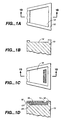
- Figures 1A, 1B, 1C, and 1D show one embodiment of a
device in which Figure 1A is a top view of
base 10. Figure 1B is a cross-section ofbase 10. Figure 1C is a top view of an assembled device taken alongplane 1B-1B in Figure 1A. Figure 1D is a cross section of an assembled device including afilter 20,lid 18, andbase 10 taken alongplane 1D-1D in Figure 1C. - Figures 2A, 2B, and 2C show another embodiment of a
device in which Figure 2A is a top view of
base 10. Figure 2B is a cross-section ofbase 10 taken alongplane 2B-2B in Figure 2A. Figure 2C is a cross section taken along the cross-sectional plane in Figure 23 of an assembled device including afilter 20,lid 18, andbase 10. - Figures 3A, 3B, and 3C show another embodiment of a
device in which Figure 3A is a top view of
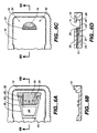
base 10. Figure 3B is a cross-section ofbase 10 taken alongplane 3B-3B in Figure 3A. Figure 3C is a cross section taken along the cross-sectional plane in Figure 3B of an assembled device including afilter 20,lid 18, andbase 10. - Figures 4A, 4B, 4C, 4D and 4E show another embodiment
of a device in which Figure 4A is a top view of
base 10. Figure 4B is a cross-section ofbase 10 viewed along theplane 4B-4B of Fig. 4A. Figure 4C is a cross section, along the same plane as Fig. 4B, of an assembled device including afilter 20,lid 18, andbase 10. Figure 4D is a top view of an embodiment comprising alid cavity 42, depicted in dashed lines. Fig. 4E is a cross section of Fig. 4D taken along the plane 4E-4E. - Figures 5A, 5B, and 5C show another embodiment of a
device in which Figure 5A is a top view of
base 10. Figure 5B is a cross-section ofbase 10 viewed along theplane 5B-5B of Fig. 5A. Figure 5C is a cross section, along the same plane as 5B, of an assembled device including afilter 20,lid 18, andbase 10. - Figures 6A, 6B, 6C and 6D show another embodiment of a
device in which Figure 6A is a top view of
base 10. Figure 6B is a cross-section ofbase 10, viewed alongplane 6B-6B of Fig. 6A. Figure 6C is a top view of an assembled device of this embodiment. Figure 6D is a cross section, viewed along the plane as 6D-6D of Fig. 6c, of an assembled device including afilter 20,lid 18, andbase 10. -
- The present invention provides for simple and rapid filtering of biological samples, whereby a sample can be analyzed in the same device or a different device.
- Accordingly the present invention provides a device comprising:
- a lid, a base substantially parallel to the lid, a fluid access port within the lid;
- a fluid permeable filter comprising a region for fluid access in fluid communication with the fluid access port and a region for fluid egress, wherein the filter comprises a substantially smaller depth dimension in comparison to its length and width dimensions, wherein the length/width plane of the filter is oriented within the device substantially parallel to the lid and base, and wherein the peripheral surfaces of the filter are sealed within the device;
- a fluid flow path through the filter that is a lateral flow path from the region for fluid access through the filter to the region for fluid egress; and
- a fluid egress port comprising a capillary space fluidly connected to the region of fluid egress from the filter, wherein fluid flows from said filter to said capillary space.
-
- Use of the device optionally comprises means for a producing an assay result in an exit region of the device.
-
- 10
- Base
- 12
- Filter Cavity
- 14
- Fluid Access Port
- 15
- Fluid Access Region of
Filter 20 - 16
- Fluid Egress Region of
Filter 20 - 17
- Exit Region
- 18
- Lid
- 20
- Filter/Filter Matrix/
Membrane 22 Compression Structure - 23
- Support Bar
- 24
- Dead Space of
Filter Cavity 12 - 26
- Sample Reservoir
- 28
- Filter Supports/Posts
- 30
- Vent Holes
- 32
- Filter Stays
- 34
- Grooves
- 36
- Lateral Compression Region of
Compression Structure 22 - 38
- Proximal Compression Region of
Compression Structure 22 - 40
- Distal Compression Region of
Compression Structure 22 - 42
- Lid Cavity
- This invention describes novel devices comprising filters for the rapid filtering of samples, particularly chemical, environmental, or biological samples, and preferably for introduction of the filtered sample into a capillary space. This invention can be utilized in any device format in accordance with the teachings provided herein. For example, although assay device filters of conventional configuration are discussed, it is understood that the principles of the application apply to devices with other configurations. In a preferred embodiment, the invention is used with the technology of devices described in U.S. Patent No. 5,458,852 to Buechler. Aspects of the invention are discussed below.
- As used herein, fluid flow will be described as follows: a conventional filter has a width, length, dimensions and substantially smaller depth ("thickness") dimension. For a filter with such dimensions, transverse flow is perpendicular to the length and width of the filter, and is predominantly in a direction parallel to the depth of the filter. Conversely, lateral flow is predominantly parallel to the length or width planes of a filter. Alternatively, a lateral flow path is a distance greater than a transverse flow path distance through a filter, typically these flow paths are oriented perpendicular to each other. In one embodiment of the invention, a lateral fluid flow path is through a filter connecting a fluid access port to a fluid egress port, where the flow path is greater than or equal to that of the greatest cross sectional distance of the filter as determined perpendicular to any point along the flow path.
- Conventional device filters comprise some degree of capillarity. To a certain extent, fluid moves through the filter due to capillary forces created, e.g., by small diameter pores or the close proximity of fibers. Fluid may move through such a filter with or without external pressure. On a micro scale relative to the filter's overall dimensions, fluid travels in multiple directions as a result of capillary forces. On a macro scale, however, fluid travels in one direction; i.e., through the filter in a predominantly lateral or transverse direction to a location where fluid can exit the filter.
- To filter a sample, either lateral or transverse fluid flow requires at least one fluid input surface and at least one fluid egress surface. A fluid input surface is defined as the filter surface where unfiltered sample fluid is placed in contact with the filter; the fluid egress surface is a filter surface from which the majority of a filtered sample fluid ("filtrate" or "filtration liquid") exits. As discussed below, a smaller amount of fluid can exit from peripheral surfaces. A peripheral surface is defined as being a surface that is not a fluid input surface and not a fluid egress surface. For transverse flow, the input and egress surfaces are the top and bottom surfaces of a conventionally shaped filter, e.g., surfaces parallel to the length and width planes. Alternatively, for a filter having lateral fluid flow, input surfaces and egress surfaces can be on the top, bottom or any surface which is not a peripheral filter surface.
- In accordance with the present disclosure, flow directionality through a device filter is lateral flow. Compared to transverse flow, lateral flow has several advantages. First, the fluid flow path can be dramatically increased in a filter of a standard configuration. For a filter of conventional shape, lateral flow yields greater filtration efficiency than transverse flow since the lateral fluid flow path is longer than the transverse fluid flow path. For example, conventional assay filters generally have a thickness of between 0.1 mm and 6 mm, approximately 2 mm is most common, with a length and width substantially longer than the thickness usually on the order of several centimeters. Thus, lateral flow yielded greater filtration efficiency with minimum effects on the device's shape. Second, lateral flow within a filter allowed the addition of fluid to any region of the filter that is not a fluid egress region, so long as fluid could laterally flow through the filter to the fluid egress region thereof. In lateral flow devices, addition of fluid to regions of the filter which are not fluid egress regions allowed fluid to enter the filter at an effectively larger area (approx. 2 times) than by entering only on one side. The larger area for fluid entrance provided a more efficient use of the filter, maximizing flow rate through the filter and minimizing the potential for clogging with particulate matter which is to be filtered from a sample.
- Additionally, incorporating a single filter rather than a stack of several filters in a device conserves device space and permits the filter to be easily situated on a device, allowing a plethora of possible design configurations.
- Various filter materials are available for filtering cells and particulate matter from biological samples. For example, cellulose fibers, nylon, glass fibers, polyester fibers or combinations of these materials are useful to make filters that remove debris from samples, e.g., cells from urine and red blood cells from plasma.
- The filter is preferably chosen such that the pores or fibrous matrix of the filter do not get clogged by particulate matter from the sample. In the case of separating red blood cells from plasma, filters generally bind, retain or retard the red blood cells and allow plasma to separate from blood and pass through the filter.
- Filters can comprise a fibrous matrix or porous material. A preferred filter is a fibrous matrix filter that is made of borosilicate glass microfibers. Borosilicate glass microfiber filters permit filtration of whole blood samples by permitting the sample (including particulate matter such as red blood cells) to penetrate the filter. For whole blood samples, the filter retards red blood cells and allows plasma to move through the fiber matrix at an nonretarded, higher flow rate. When these filters were used, and cells and plasma moved through the filter, the plasma moved further ahead of the red blood cells.
- Alternative filters can also be used which have a more porous structure, for example filters comprising nitrocellulose, acrylic copolymers, or polyethersulfone. These filters, generally, functioned differently than filters comprising fiber matrices, in view of the fact that they have pore-like passages typically of uniform diameters. Typically, a porous filter is selected such that the pore diameters are smaller than the diameters of the particulates desired to be separated from a sample. These filters retain rather than retard the red blood cells, i.e., red cells generally do not penetrate the filter beyond its surface. One skilled in the art will recognize that if the particulate matter in a sample is approximately the same size or greater than the pores of a filter, the particulate matter will rapidly clog the pores and slow or stop fluid flow therethrough.
- Thus, in accordance with the present disclosure, various filters can be used. A filter may be one of several commercially available filters including but not limited to Ahlstrom CytoSep (Mt. Holly Springs, PA) or Micro Filtration System's (Dublin, CA) glass fiber media. U.S. Patents 5,186,843; 4,774,039; 4,629,563, and 5,171,445, cover the compositions of these and like media.
- Preferably, a sample reservoir accomplishes several functions: 1) it delimits a volume which is sufficient to achieve an assay result, and thus facilitates a device user's ability to provide the suitable volume; 2) it accomplishes the foregoing while allowing for a diverse range of input volumes in a manner which does not impair an assay result; and, 3) a reservoir that is a capillary space helps to prevent fluid escape. In a preferred embodiment, the sample reservoir contained a fluid volume approximately 100 times the volume needed for downstream processing of a sample.
- As depicted in Figure 6A, 6B, 6C and 6D, a
sample reservoir 26 comprising a capillary space is incorporated into the device, whereby sample was contained in the capillary space of the sample reservoir, and the reservoir was in fluid communication with an edge, top and/or bottom of the filter (Fig. 6D). An advantage of utilizing a capillary space for introducing the sample to the filter is that the fluid, for example, a hazardous chemical, environmental or biological fluid, contained in a capillary space will tend not to spill or leak from the device. - The peripheral surfaces of the filter are sealed within the device: 1) so that fluid must flow through the filter; and 2) to prevent the fluid sample, e.g., particulates, from flowing around the filter in a capillary between the filter and the device, thus contaminating the filtrate. Sample that travels around the filter in a capillary space, rather than through the filter, can enter the
exit region 17. When unfiltered fluid entersexit region 17, the filtering efficiency of the device is decreased. "Sealing" of the peripheral surfaces need not be liquid-tight, sealing in accordance with the invention also comprises the ability to retard to flow of liquid and particulates, or particulates into spaces between the filter and the walls of the device adjacent to the filter. - There are several methods to achieve sealing of the peripheral surfaces of a filter. Preferably the sealing is liquid-tight, although some liquid release is acceptable so long as a low resistance fluid flow path outside the filter does not result. In one embodiment, the sealing permits liquid between the device wall and the filter, but retards the development of a capillary space along the peripheral surfaces and the sealing also may serve to retain particulate matter in the filter and not in any space along peripheral surfaces, due to compression. In any event, there is preferably particle-tight, more preferably liquid-tight and most preferably fluid-tight sealing of the device at or near the fluid access region 15 of
filter 20. - Regardless of the flow path direction, filter surfaces may be sealed using one or a combination of the following techniques: pressure-adhesive tapes, glues, or sealants. Such techniques require careful placement of the sealant along edges of the filter and the side walls of
filter cavity 12. A preferred liquid sealing of the peripheral surfaces is achieved by a pressure fit. A pressure fit may be achieved by placing a slightly oversized filter intofilter cavity 12 such that all the peripheral surfaces of the filter are in contact with the walls of the filter cavity. Concerning length and width dimensions, a filter is preferably 1-10% and more preferably 1 to 5% larger than the filter cavity into which it is to be placed to ensure direct contact. Compression of the depth dimension is discussed in greater detail below. Direct contact between the filter and the filter cavity walls discourages fluid from traveling between the peripheral surfaces of the filter and the filter cavity walls, because a capillary space does exist between the filter and the device walls. Thus, the perimeter or side edges of the filter will maintain contact with the walls of thefilter cavity 12 as depicted in Figure 1A. - The filter must have a degree of resilience such that it may be squeezed and hold its shape over time. The conventional media described herein have these properties and can be employed as disclosed herein to effectively seal particulates and/or liquid. The more pliable a filter is, the larger the filter must be relative to the cavity into which it is placed, so as to assure that the filter provides pressure against the cavity walls and a low resistance fluid flow path is avoided.
- To prepare a device in accordance with the invention, the shape of the filter must be approximately identical to the filter cavity, 12, (Figure 1A).
Filter cavity 12 may be of any three dimensional shape, e.g., trapezoidal, rectangular, rounded or the like. A presently preferred filter shape is that of thefilter cavity 12 of Figure 1A-1D. - Preferred embodiments of the invention make use of compression of the filter in distinct areas to limit or retard the movement of particulate matter (e.g., cells or debris) within the filter and to prevent particulate matter from escaping the filter and traveling along the peripheral filter surfaces. In the case of preventing fluid from flowing along peripheral surfaces of the filter, a compression structure 22 (e.g., see Figure 2, 3, 4 or 5A) in
filter cavity 12 helps to prevent the formation of capillary gaps between thefilter 20 and a surface to which it is in contact, e.g.,lid 18 or asurface defining cavity 12. Capillary gaps are to be avoided as they provide a low resistance flow path tofluid exit region 17, and thereby permit unfiltered sample to contaminate the filtrate. - In addition to region specific compression, liquid sealing of the filter peripheral surfaces by use of capillary force, glues, pressure-sensitive tapes, or sealants can be used to prevent particulate escape and flow of liquid along the peripheral surfaces. It is advantageous to avoid glues, pressure sensitive tapes or sealants since they have a tendency to lose their sealing properties with time; and the sealant in such materials tends to leach through the filters, potentially affecting the filtrate. In contrast, region specific filter compression leads to a lasting seal and functions without any additives or additional parts; thus, it decreases the complexity of the fabrication process and avoids potential contamination of the filtrate.
- Structures using region specific compression are shown, for example, in the embodiment depicted in Figure 4. Referring to the top view Figure 4A, a
compression structure 22 is shown. Preferred degrees of compression of the thickness offilter 20 bycompression structure 22 and an abutting surface such aslid 18, are 1 to 50% and more preferably 1 to 30% of the native thickness of the filter. Accordingly, in preferred embodiments of the device only specific regions of a filter are compressed; all regions of the filter are not compressed, and flow rate is not unduly impeded. Thus, one advantage of the present invention is that effective and rapid filtration is achieved. - The cross section view of an assemble device in Figure 4C displays a preferred height change between
filter cavity 12, andcompression structure 22. This height change results in dead space 24 (e.g., in figure 4C) underneathfilter 20 upon placement offilter 20 incavity 12. -
Dead space 24 effectively leads to liquid sealing, sincedead space 24 has minimal capillary force, and therefore does not draw any fluid away from or out offilter 20. The capillary force is low fordead space 24 due to a relatively large gap betweenfilter 20 andfilter cavity 12. - Region specific compression leads to liquid sealing yet also facilitates rapid fluid flow through the filter. The filter region depicted above the dead space is not compressed to the same degree as the filter regions between
compression structure 22 and an abutting surface. The pores or matrices of the filter are not appreciably compressed in this area and fluid flow therethrough is facilitated. It is advantageous to keep the filter noncompressed in embodiments where maximum flow rate from the fluid egress region is desired. - In summary,
dead space 24 results from certain compression structure designs and is useful for several reasons. First, it has minimal capillary force and draws no fluid into its cavity. Thus, a liquid seal is formed along the respective filter surface adjacent the dead space, forcing fluid to flow through the filter. Second, the filter adjacent to the dead space is not compressed and therefore the pore or fiber structure within the filter remains unchanged; such filter configuration is in contrast to the prior art, and advantageously produces higher flow rates. - As noted, preferred degrees of compression of
filter 20 bycompression structure 22 andlid 18 are 1 to 50%, preferably 1 to 30% of the native thickness of the filter. To achieve such compression,compression structure 22 need not be limited to one uniform level or height. Rather,compression structure 22 may be comprised of multiple sections at the same or different heights. Figure 5A displays an embodiment of the present invention in whichcompression structure 22 is comprised of sub-regions including:support bar 23,lateral compression regions 36,proximal compression region 38,distal compression region 40. Each sub-region may be sized to yield compression that facilitates sealing, filtration, or flow rate properties. In the embodiment of Figure 5, the combination ofsupport bar 23,lateral compression regions 36, anddistal compression region 38force filter 20 to be in contact withlid 18 forming a preferably liquid tight seal above each sub-region, thus facilitating prevention of flow along the peripheral surfaces of the filter.Distal region 40 does not form a liquid-tight seal, but permits liquid to exit atfluid egress region 16. Accordingly, filter 20 is not uniformly compressed, but rather is compressed only above the sub-regions ofcompression structure 22. - Another advantageous aspect of region specific compression is the ability to retard particulate matter from designated regions of the filter. Namely, to retard particulate matter from reaching either the peripheral edges or the fluid egress region of a filter. Retardation of particulate movement occurs since compression of a filter causes concomitant compression of the fiber spacing and/or pores in the filter; the compression of these microstructures makes it more difficult or impossible for particulate matter or cells to travel therethrough.
- One skilled in the art will recognize that the selective compression of the filter at the
compression structure 22 is not required for the separation of the particulate matter from the sample, but rather, such compression is but one embodiment than can be utilized for sealing the peripheral surfaces of the filter in a device and for modulating particulate movement. In a preferred embodiment, no particulate matter can exit along the peripheral surfaces or the fluid egress region offilter 20. In an alternative embodiment employingcompression structure 22, particulate matter is retarded in its movement through the filter, but nevertheless is capable of exiting the filter; in this embodiment, the exit region preferably holds the amount of liquid that is required to produce an assay (via a material(s) or modality(s) for achieving an assay result appreciated by those of skill in the art), where that volume is less than the volume of fluid that flows through he filter ahead of the retarded particulate matter. - After the particulate-free fluid has passed through the filter it is drawn into a fluid exit region 17 (see, e.g., Fig 1D).
Exit region 17 comprises higher capillarity thanfilter 20 to facilitate fluid flow therebetween. Thus, the invention utilizes capillarity force, wherebyfluid egress area 16 of the filter is immediately adjacent to exitregion 17, andregion 17 is a capillary space. Due to the use of capillarity as taught herein, fluid leaves the filter without an external pressure and uniformly fills the capillary space ofexit region 17, and fluid will not enter any region with lower capillarity than the filter, e.g.,dead space 24. Thus, capillary force can be used to cause egress of fluid from the filter and into anexit region 17 without the application of an external pressure such as hydrostatic pressure. In accordance with this embodiment, compression of the filter bycompression structure 22, in particulardistal compression region 40, should not cause the pores of the filter to be made sufficiently small such that the capillary force holding the fluid within the filter is greater than the capillarity ofexit region 17. - Advantageously, devices that incorporate filters that function by lateral flow, can be designed so that the overall device thickness is not constrained by the filter thickness.
- The filtration devices described herein generally require assembly and joining of several parts.
Lid 18 andbase 10 can be fabricated from conventional materials compatible with chemical, environmental or biological fluids to be assayed, for example: a plastic material such as acrylic, polystyrene, polycarbonate, or like polymeric materials; as well as silicon composites, such as silicon semiconductor chips; glass; or metal. In the case of plastic polymeric materials,lid 18 andbase 10 may be fabricated using thermal injection molding technology or machining. In the case of fabricating the lid and base from silicon composites, micromachining and photolithographic techniques, commonly used in the field of electronics, can be utilized to create chambers and capillaries. - The
base 10 andlid 18 are contacted together in order to form the physical configuration desired to achieve a particular result. Ultrasonic welding, adhesives, physical interfitting and heat welding are some of the methods that may be used to joinbase 10 andlid 18. For example, with embodiments comprising a lid of silicon composite or plastic, and a base of plastic or silicon composite, the base and lid can be joined with adhesives. - In a preferred embodiment, the plastic surfaces of
base 10,lid 18, or both are made hydrophilic or "wettable", whereby the contact angle between the sample fluid meniscus and thebase 10 andlid 18 is decreased. There are several ways to decrease the contact angle including but not limited to corona discharge, plasma treatment or the drying down of various surfactants or proteins onto surfaces. In accordance with standard methodologies, exposing a plastic surface to a corona discharge or plasma gas results in the formation of functional groups on the surface. The surface chemistry as well as the degree of hydrophobicity are thus modified and can be used for a variety of applications. For example, time gates, as described in U.S. Patent 5,458,852 to Buechler, can be incorporated at the fluid egress region to provide an incubation time for the sample within the filter. - One skilled in the art will recognize, in view of the present disclosure, that the filter cavity can have many possible design configurations or embodiments. The filtration concepts disclosed herein can be incorporated into a variety of devices that can be used in various assays. The following examples demonstrate presently preferred embodiments and are not intended to limit the invention.
- An embodiment of the present invention is shown in Figure 1.
Base 10 was fabricated using injection molding technology and was made of white acrylic copolymer (Polysar NAS® 30, Polysar, Inc., Madison, CT). The overall device length, width and thickness were 8.7, 3.5 and 0.26 cm respectively. The surface ofbase 10 was made hydrophilic by a corona discharge treatment. - In accordance with standard methodologies, filter cavity 12 (Figure 1A, 1B) was formed into
base 10. The filter cavity had a bilaterally symmetrical trapezoidal shape, with parallel sides 1.0 and 1.34 cm long and 0.72 cm apart. Afilter 20, slightly oversized 1-30% preferably 1-5% relative to filtercavity 12, was fitted into the cavity (Figure 1D). The filter (# GB100R, Micro Filtration Systems ("MFS"), Dublin, CA) consisted of borosilicate glass fibers; its thickness was 0.038 cm and had an absorption volume of approximately 50 µl. - A clear plastic lid 18 (Figure 1C, 1D) was coupled to
base 10 by ultrasonically welding using a Branson 941 AE welder (Branson Inc., Danbury CT) set at 50 joules and 40 psi.Bonding lid 18 tobase 10 slightly compressed thefilter 20. This compression created a seal that served to prevent fluid and particle flow around the peripheral edges offilter 20. Referring now to Figure 1D,fluid access port 14 was located directly over the filter.Lid 18 andbase 10 formed a capillary space inexit region 17 adjacent tofluid egress region 16 offilter 20. Despite the increase in capillarity by compressingfilter 20,exit region 17 comprised sufficient capillarity to draw filtrate fluid, e.g. plasma, out offilter 20. In this embodiment the exit region comprised a capillary space, where a cross section ofexit region 17 immediately abutting fluid egress region offilter 20 had dimensions approximately 25 µm by 1.0 cm. The volume encompassed by this exit region is preferably a volume sufficient to permit enough fluid to flow through the device so that an effective assay result is obtained (via a material or modality appreciated by one of ordinary skill in the art), after which the exit region is filled with fluid and flow stops; for such an embodiment an escape port is present (not illustrated) that permits release of gaseous fluids but not liquid fluids. - A use of the embodiment depicted in Figure 1 was as follows: fresh human whole blood (70 µl), that was drawn in a Vacutainer® Blood Collection Tube with acid citrate dextrose (ACD), was added to
fluid access port 14. Some of the blood was immediately absorbed intofilter 20 and the remainder formed a small droplet coveringfluid access port 14. As the fluid moved by lateral flow throughfilter 20, two distinct flow fronts formed. Since the filter retarded flow of particulates, the two flow fronts consisted of a clear plasma front preceding a dark front of red blood cells. Thus, the plasma front reachedegress region 16 of the filter before the red cells, and particulate depleted filtrate enteredexit region 17 before the red blood cell flow front reached the end of the filter. - Another embodiment of this invention is depicted in Figure 2.
Base 10 is fabricated using injection molding technology and is made of white acrylic copolymer (Polysar NAS® 30, Polysar, Inc., Madison, CT). The overall device length, width and thickness were 8.7, 3.5 and 0.26 cm respectively. The surface ofbase 10 was made hydrophilic by a corona discharge treatment. -
Base 10 comprisingcompression structure 22 was formed by conventional methods. A slightly oversized filter 20 (Figure 2C) was fitted overcompression region 22 causingdead space 24 to be defined (Figure 2C). The filter was 1-30%, preferably 1-5% larger than the portion of thefilter cavity 12 which did not include the dead spare 24. The filter (MFS filter, cat. no. GB100R Micro Filtration Systems, Dublin, CA) consisted of borosilicate glass fibers. Its thickness was 0.038 cm and had an absorption volume of approximately 50 µl. Thus, there was sealing betweenfluid access port 14 and fluid access region 15 offilter 20, so that essentially the only way sample could enter the filter was through region 15. - Advantageously, this embodiment comprises dead space 24 (Figure 2C). In prior art devices, fluid could accumulate in a capillary space between the filter and device walls around the filter. The formation of fluid in the capillary space is believed to result from a relatively high capillary force created by the close contact of the filter with the filter cavity and by the deformability of the filter. Fluid formation in such regions is undesirable since it can provide a route whereby sample does flow entirely within the filter, and if particulates enter the space separation efficiency is decreased. The present invention decreases potential fluid formation between
filter 20 and a wall ofcavity 12 by means of a space (dead space 24) that has virtually no capillary force. Therefore, so long as capillary force is used to move fluid through the filter fluid exits only from the designated region, namely,fluid egress region 16. - A clear plastic lid 18 (Figure 2C) was coupled to the base by ultrasonic welding using a Branson 941 AE welder set at 50 joules and 40 psi. Bonding of
lid 18 tobase 10 slightly compressedfilter 20 above compression structure 22: the filter was compressed by 1-50%, preferably 1-30% relative to its native thickness. This region specific compression created a sufficient seal to serve to prevent fluid flow over the peripheral surfaces of the filter at that region and to retard particles within the filter compressed at that region.Fluid access port 14 was located directly over the trapezoid-shaped filter. As shown in Fig. 2C,lid 18 andbase 10 defined a fluid egress region from thefilter 16 adjacent to the downstream edge offilter 20. A cross section ofexit region 17 immediately adjacentfluid egress region 16 had dimensions approximately 25 µm by 1.0 cm. - For the embodiment depicted in Fig. 2, a thin film lamination may be applied to the filter to increase the filter's rigidity, to avoid having the filter fall into
dead space 24 when sample is added. The lamination also prevents bending of the filter in a region where the filter is unsupported; bending can lead to flow of fluid and particulates along a peripheral surface causing contamination of the filtrate, and is generally to be avoided. Pressure sensitive tape such as ARcare ®7396 (Adhesives Research, Inc., Glen Rock, PA) is one example of a commercially available plastic lamination film which has been used. - The embodiment of Figure 2 was used as follows: Fresh human whole blood (70 µl), was drawn in a Vacutainer® Blood Collection Tube with ACD, and was added to
fluid access port 14. Some of the fluid was immediately absorbed intofilter 20, and the remainder formed a small droplet coveringfluid access port 14. Due to the retarding of particulate flow through the filter, as the fluid laterally moved throughfilter 20, two distinct flow fronts formed. The two flow fronts consisted of a clear plasma front preceding a dark front of particulate matter comprising red blood cells. Thus, the plasma front reached the downstream edge offilter 20 before the red cells, and by the time particulate matter reached the downstream edge, clear plasma had already enteredexit capillary 17.Exit capillary 17 contained material(s)/modality(s) for conducting an assay on the filtrate fluid, e.g., plasma, thus an assay was performed substantially without contamination from particulate matter, e.g., red blood cells. - In general, fluid continues to flow from
filter egress region 16 intoexit region 17 until the fluid sample ataccess port 14 is depleted into the device or until the volume that exitregion 17 can contain is filled. With this concept in mind, an embodiment of a device of the invention was designed to hold a specific volume of filtrate (e.g., plasma) inexit region 17, for example, as in devices described in U.S. Patent 5,458,852 to Buechler; once the exit region contained the specified volume of liquid, fluid flow through the device stopped. The fluid flow stopped whether or not sample remained at theaccess port 14 orsample reservoir 26; thus, the addition of too much sample had no negative affect on device function. - As depicted in Table 1, use of the embodiment of Example 2 yielded a flow rate of plasma out of
filter 20 of up to 8 µl/min. Use of this embodiment provided recovery of at least 6 µl of plasma. The effect of varying the area of filter compression at thedistal compression region 40 is shown in Table 1. As the area of thedistal compression region 40 was decreased from 0.041 in2 to 0.004 in2, the percent area of compression of thefilter 20 concomitantly decreased from 32% to 3%, and the flow rate of plasma through the filter increased from 1 µl/min to 8 µl/min at a constant filter compression of 40%. This data showed that the flow rate of fluid from the filter can be controlled by the area of the filter that is compressed.EFFECT ON FLOW RATE BY VARIATIONS OF FILTER AREA COMPRESSED AT DISTAL REGION 40 (40% FILTER THICKNESS COMPRESSION) AREA % AREA COMP FLOW RATE µl/MIN 0.041 32 1 0.028 22 2 0.014 11 4 0.004 3 8 - Figure 3 represents an alternative embodiment of a filtration device in accordance with this invention. The embodiment in Figure 3 is fabricated by conventional methodologies, such as described in Examples 1 and 2. An aspect of this embodiment is the extension of
compression structure 22 along two additional sides (lateral compression regions 36) ofbase 10. Providinglateral compression regions 36 capable of compressing the filter, diminished the possibility that fluid could create a low resistance path along the peripheral surfaces of the filter, whereby particulate matter could contaminate the filtrate. In addition, the lateral compression regions ofcompression structure 22 provided additional support for thefilter 20, minimizing the potential for thefilter 20 to touch the bottom offilter cavity 12 in any aspect ofdead space 24. - Figure 4 represents an alternative embodiment of a filtration device in accordance with the invention. This embodiment was fabricated in accordance with standard methodologies, such as those described in Examples 1 and 2. An aspect of this embodiment is
compression structure 22 which compriseslateral compression regions 36 andproximal compression region 38 so that the perimeter offilter 20 is supported and capable of being compressed. Acompression structure 22, as shown in Figure 4A, is particularly useful when a large bolus of sample is added to the device at a rapid rate. Thus, the extra support given along the edges of the filter will minimize the potential for the filter to touch the bottom of thefilter cavity 12 in any aspect ofdead space 24. - The embodiment described in this example, and depicted in Figure 4, provides a larger and more
stable compression structure 22 forfilter 20. As previously described herein,dead space 24 is beneficial because it has essentially no capillary force, and therefore,dead space 24 remains free of fluid throughout the operation of the embodiment depicted in Figure 4. - Depending on the manner of sample addition to the filtration device, that is, whether a large bolus of sample is added quickly to the filter, the degree of compression of the filter at the compression region can be increased to about 50% of the filter thickness. This amount of compression, however, impacts the flow rate through the filter. Generally, as the filter is compressed more than about 5% of the filter thickness, the flow rate of the sample moving in the filter is decreased.
- As illustrated in Figure 4D and 4E,
lid 18 incorporates alid cavity 42 which is positioned abovefilter 20 whenlid 18 is assembled tobase 10; the lid cavity does not extend into the area above the filter at thecompression structure 22. Thus,compression structure 22 is capable of compressingfilter 20 to any degree necessary to seal and holdfilter 20 infilter cavity 12 without compressing thecomplete filter 20 against thelid 18, thereby potentially slowing overall fluid flow throughfilter 20. - Table 2 shows the effect of varying the areas of the proximal 38 and lateral 36 regions, wherein the area of
distal compression region 40 was held constant. The results showed that as the total areas were increased from having no lateral or proximal compression region to a combined area of 0.05 in2, the flow rate decreased from 5 µl/min to 0.5 µl/min. - Thus, Table 2 provides data showing the impact on flow rate due to variations in the combined area of
proximal region 38 andlateral region 36 ofcompression structure 22.EFFECT OF VARIATION OF COMBINED AREAS OF PROXIMAL REGION 38 ANDLATERAL REGION 36, ON FLUID FLOW RATE(AREA OF 40 WAS CONSTANT) AREA % AREA COMP FLOW RATE µl/MIN 0 0 5 0.01 8 2 0.025 20 1 0.05 39 0.5 - Figure 5 illustrates another embodiment of
compression structure 22. Specifically,compression structure 22 was extended to comprise support bar 23 (Figure 5A, 5B), that divided dead apace.24 into two separate dead spaces.Support bar 23 ofcompression structure 22 added additional support to the filter in the area of thefilter 20 which is adjacent and slightly downstream tofluid access port 14. In addition,support bar 23 can provide for a differential compression as compared to other regions of thecompression structure 22.Support bar 23 can provide just enough compression on a small surface area of the filter such that flow of sample between a peripheral filter surface and the cavity wall is eliminated, but not so much compression as to impede or cease fluid flow through the device. - Table 3 depicts data for flow rate based on variations in the area of
distal compression region 40 ofcompression structure 22. Table 3 provides empirical data that relates flow rate, plasma recovery volume, and % filter compression for the embodiment shown in Figures 5A-C. Thus, Table 3 illustrates that compressingfilter 20 from 4% to 31% of the native filter thickness atdistal compression region 40, decreased the flow rate from about 3 µl/min to 2 µl/min while maintaining region specific compression. The data of Table 3 was taken by adding fresh human whole blood to the inlet port of devices embodied as illustrated in Figure 5. Each such device consisted of base 10 (Polysar, Polysar Incorporated, Madison, CT, NAS® 30) ultrasonically bonded tolid 18 with filter 20 (Ahlstrom CytoSep, Lot 94-49B, 0.066 cm thick) placed therebetween.Distal Filter Compression
(%)Flow rate of Plasma Exiting Filter
(µl/min.)Plasma Recovery Volume
(µl)4 3 6 15 3 6 23 2.5 8 31 2 8 - Preferably, the surface area of the
compression structure 22 that contacts filter 20 is held to a minimum. If one were to compress the entire filter, the flow rate and filtrate fluid recovery fromfilter 20 would substantially decrease because the effective porosity of the total filter would be lowered. - In each of Examples 2-5, the sealing of
filter 20 comprised use of compression in certain regions offilter 20. With each example, a variation in the shape ofcompression structure 22 was made. The choice of a compression region configuration for use with a particulate sample is appreciated readily by one of ordinary skill in the art in view of the present disclosure, based on the extent to which one wishes to emphasize parameters such as filter support, flow rate or particle retardation. For example, inclusion ofcompression structure 22 in Figure 3 reduced the leakage of red blood cells into the plasma and increased separation efficiency while maximizing flow rate. - Figure 6A-D illustrates a presently preferred embodiment of the invention. This embodiment provided a sample reservoir 26 (Figure 6D) which safely contains a fluid sample.
Sample reservoir 26 preferably comprises a capillary space, and is in fluid communication withfilter 20 andexit region 17. - The embodiment depicted in Figure 6 was fabricated as follows:
base 10 was fabricated using injection molding technology and was made of white acrylic copolymer (Polysar NAS® 30). The overall device length, width and thickness were approximately 8.7, 3.5 and 0.26 cm, respectively. The surface ofbase 10 was made hydrophilic by treatment with a gas plasma in accordance with standard methodologies, alternatively corona discharge treatment was used to make the surface hydrophilic. - As depicted in Figure 6D, a slightly
oversized filter 20 was fitted overcompression structure 22 and a dual regiondead space 24. Filter 20 (Ahlstrom CytoSep® filter, Mt. Holly Springs, PA) comprised a mixture of cellulose, borosilicate glass, and polyester fibers. Its thickness was 0.063 cm and had an absorption volume of approximately 200 µl. To enhance filter support, filter posts 28 were added, these posts are believed to improve the stability and positioning offilter 20. -
Lid 18, formed of clear plastic, was ultrasonically welded tobase 10. The lid had dimensions of approximately 8, 2.5 and 0.1 cm.Bonding lid 18 tobase 10 resulted in a slight compression offilter 20 of approximately 4% relative to its native thickness. Region-specific compression atstructure 22 created a seal that helped to prevent fluid and particle flow over peripheral surfaces offilter 20. - Tables 4-6 contain flow rate data for
exit region 17. The data for Tables 4-6 were obtained from experiments wherein at least 15 µl of filtrate fluid was obtained. - For example, as indicated in Table 4, a 25% compression of
filter 20 bycompression structure 22 slowed the flow rate of the sample by as much as 23% in the filter. Increasing the compression to about 50% decreased the flow rate by up to 61%.EFFECT ON FLUID FLOW BY FILTER COMPRESSION (THICKNESS) BY DISTAL COMPRESSION REGION 40 OFCOMPRESSION STRUCTURE 22% Compression Flow Rate µl/min % decrease in fluid flow 1 6.4 Control 25 4.9 23% 50 2.5 61% - Table 5 shows the effect of filter compression by
support bar 23 on the fluid flow from the filter. A constant 1% compression offilter 20 at thedistal compression region 40 was the control. As the compression of the filter thickness bysupport bar 23 increased from 1% to 50%, the flow rate dropped from 6.4 µl/min to 1.7 µl/min.EFFECT ON FLUID FLOW BY FILTER COMPRESSION (THICKNESS) BY SUPPORT BAR 23% Compression Flow Rate µl/min % decrease in fluid flow 1 6.4 Control 25 3.0 53% 50 1.7 73% - Table 6 shows the effect of filter compression at both
distal region 40 andsupport bar 23, on fluid flow rate from the filter. As the compression regions increased filter compression from 1% to 50%, the flow rate decreased from 6.4 µl/min to 1.8 µl/min.EFFECT ON FLUID FLOW BY FILTER COMPRESSION (THICKNESS) BY DISTAL REGION 40 ANDSUPPORT BAR 23% Compression Flow Rate µl/min % decrease in fluid flow 1 6.4 Control 25 2.9 55% 50 1.8 72% - The sample flow rate decreased since pores or matrices of the filter are made smaller by compression and the resistance to flow is increased. As disclosed herein, compression of the filter at
compression structure 22 can be as great as 50% iflid 18 has been modified to compriselid cavity 42, as shown in Figure 4D, without a substantial decrease in fluid flow rate. -
Fluid access port 14 was located oversample reservoir 26. One skilled in the art will recognize that thefluid access port 14 can be situated over thesample reservoir 26, as well as a portion of filter 20 (Figure 6D).Lid 18 andbase 10 formed a fluid exit region 17 (Figure 6D) adjacent to the downstream edge of filter 20 (i.e., adjacentfluid egress region 16 of filter 20). The fluid exit region comprises a capillary space.Exit region 17 had cross-sectional dimensions adjacentfilter egress region 16 of 25 µm by 1.0 cm to create a capillary gap (also referred to herein as a capillary space). The dimension of a fluid egress region comprising a capillary can vary from about 0.1 µm to about 100 µm, and most preferably from about 10 µm to 50 µm. - The capillarity of
exit region 17 was important for fluid to be drawn into the exit region without an external applied pressure at any point before or along the flow path. The relative capillarity offilter 20 and theexit region 17 were designed to provide fluid movement from the filter into the exit capillary. Thus,exit region 17 will have the highest capillarity,filter 20 will have intermediate capillarity andsample reservoir 26 will have lowest capillarity. The capillarity of the sample reservoir should not be so great as to prevent fluid from entering the filter and the downstream capillaries of the device, particularly devices as described in U.S. Patent 5,458,852. - As depicted in Figure 6D,
sample reservoir 26, is in fluid communication with the top, bottom and edge offilter 20. One skilled in the art will recognize that the surface area of the filter in contact with fluid insample reservoir 26 can be varied, and that maximizing the surface area of the filter in contact with fluid will improve the filtration characteristics of the filter because particulate matter incapable of penetrating the filter is spread out over a larger area, whereby the filter will have a lower tendency to clog. -
Sample reservoir 26 also facilitates addition of various volumes of sample to the device. One skilled in the art will recognize that the volume of thesample reservoir 26 should be adjusted to accommodate the volume of sample to be assayed by the device. Preferred volumes for the sample reservoir are between 0.1 µl and 1000 µl, and particularly preferred volumes are between 5 µl and 300 µl. - In one embodiment,
sample reservoir 26 comprises a capillary space when alid 18 is attached to thebase 10; therefore, the dimensions of the capillary gap of thereservoir 26 are designed in accordance with the capillarity of the regions of the entire device, so that there will be fluid flow and filtration. - Advantageously, the capillary force of the
fluid reservoir 26 held the fluid sample within the reservoir and minimized the risk of spilling or expulsion of fluid sample from the device. This is particularly advantageous when the fluid sample is, e.g., a biological fluid that may be contaminated with hazardous bacteria or virus, or is an environmental water sample contaminated with pollutants. - Preferably,
reservoir 26 comprises vent holes 30 inlid 18. Vent holes 30 allow escape of air fromreservoir 28 during filling with the fluid sample, and facilitate more complete filling of the reservoir. - A particularly preferred embodiment of the
sample reservoir 26, as illustrated in Figure 6, comprisesgrooves 34 on the floor ofreservoir 26 and on the filter stay 32. In the absence of grooves (or other suitable texture), when the floor of thesample reservoir 26 was flat, some sample fluid was retained by capillary action in the corners of thesample reservoir 26. In one embodiment,grooves 34 are approximately 0.013 cm deep and 0.043 cm wide and are oriented such that the sample fluid is directed to filter 20 by flowing alonggrooves 34. Thus, the sample fluid completely drained from the corners of thesample reservoir 26, sincegrooves 34 served to break the capillary tension of the sample fluid meniscus that formed in the corners ofsample reservoir 26 that occurred as sample fluid was depleted from the reservoir. - One skilled in the art will recognize that the size and orientation of the grooves can be changed and the grooves could be substituted for a surface texture of posts protruding from the floor of the sample reservoir without changing the scope of this invention.
- In the particular embodiment with dimensions discussed in this example, fresh human whole blood (220 µl), drawn in a Vacutainer® Blood Collection Tube with EDTA, was added through
fluid access port 14, intosample reservoir 26; the fluid simultaneously began to flow intofilter 20. Blood continued to move fromsample reservoir 26 intofilter 20 becausefilter 20 had a stronger capillary force thansample reservoir 26. The fluid flowed laterally throughfilter 20, and two distinct flow fronts developed, the leading front being clear plasma and the trailing front comprising particulate material such as red blood cells. The plasma front reached the downstream edge of filter 20 (i.e., fluid egress region 16) after about 50 seconds at which point the plasma front was approximately 2 mm ahead of the red blood cell front. Withinfilter 20 having dimensions disclosed above, the volume of plasma that a 2 mm distance corresponded to was approximately 20 to 30 µl. This volume represented the amount of plasma available for an assay before the red blood cells reached the downstream edge offilter 20 and could move intoexit region 17; this configuration was selected because a volume of 15 to 20 µl was necessary to obtain an assay result. Fluid flow throughfilter 20 was enhanced by the capillary force ofexit region 17. As noted above,exit region 17 comprised a capillary space, and plasma exited the filter and enteredexit region 17 by capillary action, at a flow rate of approximately 7 µl/min. Approximately 15 to 20 µl of plasma was recovered and was devoid of red blood cells. - In a preferred embodiment, to minimize the possibility that a filtrate fluid in
exit region 17 might be contaminated with particulate matter, the exit region was designed to accommodate a volume which corresponded to the volume of fluid that was equal to or less than that which precedes the particulate matter front for a given device embodiment. Thus, in the embodiment depicted in Figure 6, with dimensions as set forth above, the exit region was designed to accommodate 20-30 µl or less.
Claims (19)
- A device comprising:a lid 18, a base 10 substantially parallel to the lid, a fluid access port 14 within the lid;a fluid permeable filter 20 comprising a region for fluid access 15 in fluid communication with the fluid access port 14 and a region for fluid egress 16, wherein the filter comprises a substantially smaller depth dimension in comparison to its length and width dimensions, wherein the length/width plane of the filter is oriented within the device substantially parallel to the lid 18 and base 10, and wherein the peripheral surfaces of the filter 20 are sealed within the device;a fluid flow path through the filter that is a lateral flow path from the region for fluid access 15 through the filter to the region for fluid egress 16; anda fluid egress port comprising a capillary space 17 fluidly connected to the region of fluid egress 16 from the filter 20, wherein fluid flows from said filter to said capillary space.
- The device of claim 1, wherein the peripheral surfaces of the filter 20 are sealed within the device in a fluid tight manner.
- The device of claim 1, further comprising a dead space 24 defined by a peripheral surface of the filter and a region of the device.
- The device of claim 1, further comprising a means for retarding movement of any particulate matter in the filter through a peripheral surface of the filter.
- The device of claim 4, wherein the filter 20 is sealed in a particle-tight manner on all peripheral surfaces, whereby for a sample comprising particulate matter, any particulate matter in the filter is retained in the filter and any fluid in a capillary space along a peripheral surface of the filter is free of particulate matter.
- The device of claim 5, wherein the filter is sealed in a liquid-tight manner on all peripheral surfaces.
- The device of claim 5, wherein the filter is sealed in a fluid-tight manner on all peripheral surfaces.
- The device of claim 1, further comprising a means for region-specific compression.
- The device of claim 8, wherein the means for region-specific compression further comprises use of fluid-impermeable glue, a sealant, or a pressure adhesive tape.
- The device of claim 8, wherein the means for region-specific compression comprises compressing the filter matrix 20 between two or more solid surfaces.
- The device of claim 1 further comprising a sample reservoir 26 fluidly connected to the sample access region 15 of the filter.
- The device of claim 11 wherein the sample reservoir 26 comprises a capillary space.
- The device of claim 1 wherein the capillary space 17 fluidly connected to the fluid egress region 16 comprises a means for producing an assay result.
- A method for assaying fluid samples, the method comprising adding fluid to the fluid access region 15 of the device of claim 11.
- The device of claim 1 wherein the capillary space 17 fluidly connected to the fluid egress port comprises a means for producing an assay result, wherein the assay means requires a set volume of liquid to produce an assay result.
- The device of claim 15 wherein the capillary space 17 fluidly connected to the fluid egress port is adapted to contain a volume that is at least the set volume of liquid required to produce an assay result.
- A method for producing an assay result, the method comprising adding a volume of fluid sample to the sample access port 14 of the device of claim 15, wherein the volume is greater than or equal to the volume required by the assay means to produce an assay result.
- The device of claim 8, wherein the means for region-specific compression comprises compression of the filter by 1-50% of the native thickness of the filter.
- The device of claim 1, wherein sample fluid substantially devoid of particulate matter is released from the filter 20 through the fluid egress port.
Priority Applications (1)
| Application Number | Priority Date | Filing Date | Title |
|---|---|---|---|
| EP02077188A EP1236514B1 (en) | 1996-08-26 | 1997-08-25 | Devices incorporating filter with region-specific compression |
Applications Claiming Priority (3)
| Application Number | Priority Date | Filing Date | Title |
|---|---|---|---|
| US704804 | 1996-08-26 | ||
| US08/704,804 US6391265B1 (en) | 1996-08-26 | 1996-08-26 | Devices incorporating filters for filtering fluid samples |
| PCT/US1997/014939 WO1998008606A2 (en) | 1996-08-26 | 1997-08-25 | Devices incorporating filters for filtering fluid samples |
Related Child Applications (1)
| Application Number | Title | Priority Date | Filing Date |
|---|---|---|---|
| EP02077188A Division EP1236514B1 (en) | 1996-08-26 | 1997-08-25 | Devices incorporating filter with region-specific compression |
Publications (2)
| Publication Number | Publication Date |
|---|---|
| EP0920356A2 EP0920356A2 (en) | 1999-06-09 |
| EP0920356B1 true EP0920356B1 (en) | 2002-12-18 |
Family
ID=24830930
Family Applications (2)
| Application Number | Title | Priority Date | Filing Date |
|---|---|---|---|
| EP97938586A Expired - Lifetime EP0920356B1 (en) | 1996-08-26 | 1997-08-25 | Devices incorporating filters for filtering fluid samples |
| EP02077188A Expired - Lifetime EP1236514B1 (en) | 1996-08-26 | 1997-08-25 | Devices incorporating filter with region-specific compression |
Family Applications After (1)
| Application Number | Title | Priority Date | Filing Date |
|---|---|---|---|
| EP02077188A Expired - Lifetime EP1236514B1 (en) | 1996-08-26 | 1997-08-25 | Devices incorporating filter with region-specific compression |
Country Status (8)
| Country | Link |
|---|---|
| US (2) | US6391265B1 (en) |
| EP (2) | EP0920356B1 (en) |
| AT (1) | ATE229845T1 (en) |
| AU (1) | AU4088197A (en) |
| CA (1) | CA2263976C (en) |
| DE (2) | DE69718011T2 (en) |
| ES (1) | ES2185984T3 (en) |
| WO (1) | WO1998008606A2 (en) |
Cited By (2)
| Publication number | Priority date | Publication date | Assignee | Title |
|---|---|---|---|---|
| US10071373B2 (en) | 2014-08-08 | 2018-09-11 | Ortho-Clinical Diagnostics, Inc. | Lateral-flow assay device having flow constrictions |
| US11033896B2 (en) | 2014-08-08 | 2021-06-15 | Ortho-Clinical Diagnostics, Inc. | Lateral-flow assay device with filtration flow control |
Families Citing this family (76)
| Publication number | Priority date | Publication date | Assignee | Title |
|---|---|---|---|---|
| US6767510B1 (en) | 1992-05-21 | 2004-07-27 | Biosite, Inc. | Diagnostic devices and apparatus for the controlled movement of reagents without membranes |
| US6905882B2 (en) * | 1992-05-21 | 2005-06-14 | Biosite, Inc. | Diagnostic devices and apparatus for the controlled movement of reagents without membranes |
| US6113855A (en) * | 1996-11-15 | 2000-09-05 | Biosite Diagnostics, Inc. | Devices comprising multiple capillarity inducing surfaces |
| US6194222B1 (en) * | 1998-01-05 | 2001-02-27 | Biosite Diagnostics, Inc. | Methods for monitoring the status of assays and immunoassays |
| US7713703B1 (en) | 2000-11-13 | 2010-05-11 | Biosite, Inc. | Methods for monitoring the status of assays and immunoassays |
| EP2283924B1 (en) * | 2001-08-28 | 2013-04-17 | Gyros Patent Ab | Inlet unit with means supporting liquid entrance into a microchannel structure |
| JP4191051B2 (en) * | 2002-02-27 | 2008-12-03 | 三光純薬株式会社 | Plasma or serum separator |
| SE0201738D0 (en) * | 2002-06-07 | 2002-06-07 | Aamic Ab | Micro-fluid structures |
| JP4210783B2 (en) | 2002-09-26 | 2009-01-21 | アークレイ株式会社 | Analysis tool |
| JP4262466B2 (en) | 2002-10-28 | 2009-05-13 | アークレイ株式会社 | Analysis tool and analyzer |
| EP1557663B1 (en) * | 2002-11-01 | 2007-08-01 | ARKRAY, Inc. | Measuring instrument provided with sold component concentrating means |
| SE527896C2 (en) * | 2003-05-20 | 2006-07-04 | Aamic Ab | Optical test device for biological samples, as well as a microarray for the device and the method for its use |
| JP2007530946A (en) * | 2004-03-23 | 2007-11-01 | クイデル コーポレイション | Hybrid phase lateral flow assay |
| SE0400662D0 (en) * | 2004-03-24 | 2004-03-24 | Aamic Ab | Assay device and method |
| SE527036C2 (en) * | 2004-06-02 | 2005-12-13 | Aamic Ab | Controlled flow analysis device and corresponding procedure |
| DE102004027422A1 (en) * | 2004-06-04 | 2005-12-29 | Boehringer Ingelheim Microparts Gmbh | Device for receiving blood and separating blood components |
| DK1843850T3 (en) | 2005-01-31 | 2015-12-07 | Realbio Technologies Ltd | LATERAL FLOW STEERING CAPILLAR DEVICE |
| US7648844B2 (en) * | 2005-05-02 | 2010-01-19 | Bioscale, Inc. | Method and apparatus for detection of analyte using an acoustic device |
| US7749445B2 (en) * | 2005-05-02 | 2010-07-06 | Bioscale, Inc. | Method and apparatus for analyzing bioprocess fluids |
| US7300631B2 (en) * | 2005-05-02 | 2007-11-27 | Bioscale, Inc. | Method and apparatus for detection of analyte using a flexural plate wave device and magnetic particles |
| US7611908B2 (en) * | 2005-05-02 | 2009-11-03 | Bioscale, Inc. | Method and apparatus for therapeutic drug monitoring using an acoustic device |
| WO2006132666A1 (en) * | 2005-06-06 | 2006-12-14 | Decision Biomarkers, Inc. | Assays based on liquid flow over arrays |
| SE529254C2 (en) * | 2005-06-17 | 2007-06-12 | Aamic Ab | Optical test system |
| SE0501418L (en) | 2005-06-20 | 2006-09-26 | Aamic Ab | Method and means for effecting liquid transport |
| RU2423073C2 (en) * | 2005-07-14 | 2011-07-10 | Нано-Дайтек Корпорейшн | Nicrofluidic devices and methods of their preparation and application |
| ATE472100T1 (en) * | 2005-09-06 | 2010-07-15 | Hoffmann La Roche | DEVICE WITH COMPRESSABLE MATRIX AND HOMOGENEOUS FLOW PROFILE |
| US7871568B2 (en) * | 2006-01-23 | 2011-01-18 | Quidel Corporation | Rapid test apparatus |
| US7794656B2 (en) * | 2006-01-23 | 2010-09-14 | Quidel Corporation | Device for handling and analysis of a biological sample |
| SE529711C2 (en) | 2006-03-22 | 2007-11-06 | Aamic Ab | Fluorescence Readers |
| EP2038658B1 (en) | 2006-06-20 | 2013-03-20 | Amic AB | Assay device |
| SE531948C2 (en) * | 2006-06-20 | 2009-09-15 | Aamic Ab | Liquid sample analyzer including filters in direct contact with projections |
| US20100311186A1 (en) * | 2006-07-28 | 2010-12-09 | Biosite Incorporated | Devices and methods for performing receptor binding assays using magnetic particles |
| WO2008060607A2 (en) | 2006-11-14 | 2008-05-22 | Biosite Incorporated | Methods and compositions for monitoring and risk prediction in cardiorenal syndrome |
| WO2008061149A2 (en) | 2006-11-14 | 2008-05-22 | Biosite Incorporated | Methods and compositions for diagnosis and prognosis of renal artery stenosis |
| WO2009033056A1 (en) * | 2007-09-06 | 2009-03-12 | Bioscale, Inc. | Reusable detection surfaces and methods of using same |
| WO2009068027A1 (en) * | 2007-11-26 | 2009-06-04 | Atonomics A/S | Separation and detection device |
| US20100264099A1 (en) * | 2007-11-26 | 2010-10-21 | Atonomics A/S | Separation device comprising a physical barrier |
| JP2011504591A (en) * | 2007-11-26 | 2011-02-10 | アトノミックス アクティーゼルスカブ | Integrated separation and detection cartridge with means and methods for increasing the signal to noise ratio |
| WO2009075709A1 (en) * | 2007-12-12 | 2009-06-18 | Micropoint Bioscience Inc | Rapid and efficient filtering whole blood in a capillary flow device |
| US9968931B2 (en) * | 2007-12-12 | 2018-05-15 | Nan Zhang | Rapid and efficient filtering whole blood in capillary flow device |
| KR100912531B1 (en) * | 2007-12-17 | 2009-08-18 | 한국전자통신연구원 | Filter chip and Method for manufacturing filter chip |
| WO2009109997A1 (en) | 2008-03-07 | 2009-09-11 | Advanced Microdevices Pvt Ltd | Method and device for particle removal and droplet preparation for qualitative and quantitative bioanalysis |
| US9952211B2 (en) | 2008-06-29 | 2018-04-24 | Realbio Technologies Ltd. | Liquid-transfer device particularly useful as a capturing device in a biological assay process |
| WO2010005467A2 (en) | 2008-07-09 | 2010-01-14 | Micropoint Bioscience Inc | Analytical cartridge with fluid flow control |
| EP2269737B1 (en) * | 2009-07-02 | 2017-09-13 | Amic AB | Assay device comprising serial reaction zones |
| EP2473284A1 (en) * | 2009-09-01 | 2012-07-11 | Koninklijke Philips Electronics N.V. | Fluid filtering device |
| WO2011041572A1 (en) * | 2009-09-30 | 2011-04-07 | Conocophillips Company | Double string pump for hydrocarbon wells |
| EP2646822B1 (en) | 2010-11-29 | 2017-11-01 | Alere San Diego, Inc. | Methods for diagnosis and risk prediction in heart failure |
| WO2012137506A1 (en) * | 2011-04-08 | 2012-10-11 | パナソニック株式会社 | Diagnosis kit and diagnosis method |
| SE1150848A1 (en) * | 2011-09-19 | 2013-03-20 | Method and apparatus for treating a patient sample | |
| WO2013082273A1 (en) * | 2011-11-30 | 2013-06-06 | Wellstat Diagnostics, Llc. | Filtration module |
| CN105833925B (en) | 2011-12-22 | 2018-11-13 | 瑞尔比奥技术有限公司 | sequential lateral flow capillary device for analyte determination |
| US9213043B2 (en) | 2012-05-15 | 2015-12-15 | Wellstat Diagnostics, Llc | Clinical diagnostic system including instrument and cartridge |
| US9625465B2 (en) | 2012-05-15 | 2017-04-18 | Defined Diagnostics, Llc | Clinical diagnostic systems |
| US9075042B2 (en) | 2012-05-15 | 2015-07-07 | Wellstat Diagnostics, Llc | Diagnostic systems and cartridges |
| US9386948B2 (en) | 2012-12-05 | 2016-07-12 | Theranos, Inc. | Systems, devices, and methods for bodily fluid sample transport |
| US10248765B1 (en) | 2012-12-05 | 2019-04-02 | Theranos Ip Company, Llc | Systems, devices, and methods for bodily fluid sample collection, transport, and handling |
| US9097624B1 (en) * | 2013-03-01 | 2015-08-04 | The United States Of America As Represented By The Secretary Of The Army | External filter assembly adapted for modifying a suction cleaning device to perform biological sampling |
| US20140323911A1 (en) * | 2013-03-15 | 2014-10-30 | Theranos, Inc. | Methods and devices for sample collection and sample separation |
| CA2906810A1 (en) | 2013-03-15 | 2014-09-18 | Theranos, Inc. | Methods and devices for sample collection and sample separation |
| WO2015021308A1 (en) | 2013-08-07 | 2015-02-12 | Astute Medical, Inc. | Assays for timp2 having improved performance in biological samples |
| CA3185700A1 (en) | 2013-11-06 | 2015-05-14 | Astute Medical, Inc. | Assays for igfbp7 having improved performance in biological samples |
| US10073091B2 (en) * | 2014-08-08 | 2018-09-11 | Ortho-Clinical Diagnostics, Inc. | Lateral flow assay device |
| WO2016122560A1 (en) * | 2015-01-30 | 2016-08-04 | Hewlett-Packard Development Company, L.P. | Vented microfluidic reservoirs |
| JP1530328S (en) * | 2015-02-17 | 2015-08-03 | ||
| US10371606B2 (en) | 2015-07-21 | 2019-08-06 | Theraos IP Company, LLC | Bodily fluid sample collection and transport |
| WO2017044888A1 (en) | 2015-09-09 | 2017-03-16 | Theranos, Inc. | Methods and devices for sample collection and sample separation |
| CN105536898B (en) * | 2015-12-14 | 2017-07-07 | 清华大学 | The preparation method of micro-fluidic chip, haemocyte separation method and system and the system |
| US11857966B1 (en) | 2017-03-15 | 2024-01-02 | Labrador Diagnostics Llc | Methods and devices for sample collection and sample separation |
| US11718682B2 (en) | 2017-04-05 | 2023-08-08 | Astute Medical, Inc. | Assays for TIMP2 having improved performance in biological samples |
| EP3460077B1 (en) | 2017-09-20 | 2020-06-17 | Altratech Limited | Diagnostic device and system |
| CN111108216B (en) | 2017-09-20 | 2024-02-23 | 阿尔查技术有限公司 | Diagnostic device and system |
| CN112041341A (en) | 2017-12-28 | 2020-12-04 | 机敏医药股份有限公司 | Antibodies and detection of CCL14 |
| CN113101985B (en) * | 2019-06-26 | 2022-07-22 | 京东方科技集团股份有限公司 | Detection chip and detection system |
| MX2022015287A (en) | 2020-06-01 | 2023-02-22 | Loop Diagnostics S L | Method and kit for the early detection of sepsis. |
| CN115575280B (en) * | 2022-12-06 | 2023-02-28 | 广州云舟智慧城市勘测设计有限公司 | Water flow sand content sampling and detecting device for water conservancy survey |
Citations (1)
| Publication number | Priority date | Publication date | Assignee | Title |
|---|---|---|---|---|
| US5516488A (en) * | 1991-11-11 | 1996-05-14 | British Technology Group Limited | Liquid transfer devices |
Family Cites Families (31)
| Publication number | Priority date | Publication date | Assignee | Title |
|---|---|---|---|---|
| US1986957A (en) * | 1934-09-17 | 1935-01-08 | Edward Perlman | Filter holder |
| NL286850A (en) * | 1961-12-18 | 1900-01-01 | ||
| US3620375A (en) * | 1969-09-08 | 1971-11-16 | Jack Atkins | Filter constructed of metallic material |
| US3747769A (en) * | 1971-08-02 | 1973-07-24 | R Brumfield | Compressible disposable filter press for blood |
| US4774039A (en) | 1980-03-14 | 1988-09-27 | Brunswick Corporation | Dispersing casting of integral skinned highly asymmetric polymer membranes |
| US4629563B1 (en) | 1980-03-14 | 1997-06-03 | Memtec North America | Asymmetric membranes |
| DE3029579C2 (en) | 1980-08-05 | 1985-12-12 | Boehringer Mannheim Gmbh, 6800 Mannheim | Method and means for separating plasma or serum from whole blood |
| US4678757A (en) | 1985-04-11 | 1987-07-07 | Smithkline Diagnostics, Inc. | Device and method for whole blood separation and analysis |
| US5081017A (en) * | 1986-02-18 | 1992-01-14 | Texas Bioresource Corporation | Method and apparatus for detection and quantitation of bacteria |
| US4753776A (en) | 1986-10-29 | 1988-06-28 | Biotrack, Inc. | Blood separation device comprising a filter and a capillary flow pathway exiting the filter |
| US5135719A (en) * | 1986-10-29 | 1992-08-04 | Biotrack, Inc. | Blood separation device comprising a filter and a capillary flow pathway exiting the filter |
| US5593580A (en) * | 1986-11-26 | 1997-01-14 | Kopf; Henry B. | Filtration cassette article, and filter comprising same |
| US4987085A (en) | 1987-06-22 | 1991-01-22 | Chemtrak Inc. | Blood filtering metering device |
| DE3875860T2 (en) * | 1987-08-21 | 1993-03-25 | Takano Corp | FILTER WITH DEEP EFFECT. |
| CA1318588C (en) | 1988-01-19 | 1993-06-01 | Henry Jeong | Method and device for separating plasma from red cells |
| AU2684488A (en) * | 1988-06-27 | 1990-01-04 | Carter-Wallace, Inc. | Test device and method for colored particle immunoassay |
| US5202268A (en) * | 1988-12-30 | 1993-04-13 | Environmental Diagnostics, Inc. | Multi-layered test card for the determination of substances in liquids |
| US5087556A (en) * | 1989-05-17 | 1992-02-11 | Actimed Laboratories, Inc. | Method for quantitative analysis of body fluid constituents |
| US5147609A (en) * | 1989-05-19 | 1992-09-15 | Pb Diagnostic Systems, Inc. | Assay element |
| US5435970A (en) | 1989-12-18 | 1995-07-25 | Environmental Diagnostics, Inc. | Device for analysis for constituents in biological fluids |
| DE4015589A1 (en) | 1990-05-15 | 1991-11-21 | Boehringer Mannheim Gmbh | DEVICE AND THE USE THEREOF FOR SEPARATING PLASMA FROM WHOLE BLOOD |
| US5139685A (en) * | 1991-03-26 | 1992-08-18 | Gds Technology, Inc. | Blood separation filter assembly and method |
| US5171445A (en) | 1991-03-26 | 1992-12-15 | Memtec America Corporation | Ultraporous and microporous membranes and method of making membranes |
| US5186843A (en) | 1991-07-22 | 1993-02-16 | Ahlstrom Filtration, Inc. | Blood separation media and method for separating plasma from whole blood |
| US5458852A (en) | 1992-05-21 | 1995-10-17 | Biosite Diagnostics, Inc. | Diagnostic devices for the controlled movement of reagents without membranes |
| DE4323672A1 (en) * | 1993-07-15 | 1995-01-19 | Boehringer Mannheim Gmbh | Device for the simultaneous determination of analytes |
| GB9324310D0 (en) | 1993-11-26 | 1994-01-12 | Univ Birmingham | Liquid transfer device |
| DE4432627B4 (en) * | 1994-09-14 | 2008-09-25 | Sartorius Stedim Biotech Gmbh | Filtration unit for the separation of substances with membrane adsorbers |
| DE4432628B4 (en) * | 1994-09-14 | 2008-01-10 | Sartorius Biotech Gmbh | Dead-end filtration unit for separating substances with membrane adsorbers |
| US5916521A (en) * | 1995-01-04 | 1999-06-29 | Spectral Diagnostics, Inc. | Lateral flow filter devices for separation of body fluids from particulate materials |
| DE60300826T2 (en) * | 2002-01-25 | 2006-05-18 | Inoac Corp., Nagoya | fluid filter |
-
1996
- 1996-08-26 US US08/704,804 patent/US6391265B1/en not_active Expired - Lifetime
-
1997
- 1997-08-25 DE DE69718011T patent/DE69718011T2/en not_active Expired - Lifetime
- 1997-08-25 EP EP97938586A patent/EP0920356B1/en not_active Expired - Lifetime
- 1997-08-25 ES ES97938586T patent/ES2185984T3/en not_active Expired - Lifetime
- 1997-08-25 DE DE69739668T patent/DE69739668D1/en not_active Expired - Lifetime
- 1997-08-25 WO PCT/US1997/014939 patent/WO1998008606A2/en active IP Right Grant
- 1997-08-25 CA CA002263976A patent/CA2263976C/en not_active Expired - Lifetime
- 1997-08-25 EP EP02077188A patent/EP1236514B1/en not_active Expired - Lifetime
- 1997-08-25 AU AU40881/97A patent/AU4088197A/en not_active Abandoned
- 1997-08-25 AT AT97938586T patent/ATE229845T1/en not_active IP Right Cessation
-
2002
- 2002-05-21 US US10/153,423 patent/US7588730B2/en not_active Expired - Fee Related
Patent Citations (1)
| Publication number | Priority date | Publication date | Assignee | Title |
|---|---|---|---|---|
| US5516488A (en) * | 1991-11-11 | 1996-05-14 | British Technology Group Limited | Liquid transfer devices |
Cited By (3)
| Publication number | Priority date | Publication date | Assignee | Title |
|---|---|---|---|---|
| US10071373B2 (en) | 2014-08-08 | 2018-09-11 | Ortho-Clinical Diagnostics, Inc. | Lateral-flow assay device having flow constrictions |
| US11033896B2 (en) | 2014-08-08 | 2021-06-15 | Ortho-Clinical Diagnostics, Inc. | Lateral-flow assay device with filtration flow control |
| US11931734B2 (en) | 2014-08-08 | 2024-03-19 | Ortho-Clinical Diagnostics, Inc. | Lateral-flow assay device having flow constrictions |
Also Published As
| Publication number | Publication date |
|---|---|
| DE69718011T2 (en) | 2003-09-25 |
| US7588730B2 (en) | 2009-09-15 |
| CA2263976C (en) | 2006-05-16 |
| WO1998008606A3 (en) | 1998-07-16 |
| ES2185984T3 (en) | 2003-05-01 |
| US20030035758A1 (en) | 2003-02-20 |
| US6391265B1 (en) | 2002-05-21 |
| ATE229845T1 (en) | 2003-01-15 |
| WO1998008606A2 (en) | 1998-03-05 |
| EP1236514B1 (en) | 2009-11-18 |
| EP0920356A2 (en) | 1999-06-09 |
| CA2263976A1 (en) | 1998-03-05 |
| DE69739668D1 (en) | 2009-12-31 |
| DE69718011D1 (en) | 2003-01-30 |
| AU4088197A (en) | 1998-03-19 |
| EP1236514A3 (en) | 2004-01-28 |
| EP1236514A2 (en) | 2002-09-04 |
Similar Documents
| Publication | Publication Date | Title |
|---|---|---|
| EP0920356B1 (en) | Devices incorporating filters for filtering fluid samples | |
| US4895706A (en) | Multi-well filter strip and composite assemblies | |
| US6783732B2 (en) | Apparatus and method for avoiding cross-contamination due to pendent drops of fluid hanging from discharge conduits | |
| US8623296B2 (en) | Microfluidic size-exclusion devices, systems, and methods | |
| EP3645998B1 (en) | Sample filtration device and method | |
| EP0333119A2 (en) | Liquid filtering device | |
| AU3263199A (en) | Apparatus for, and method of, varying the rate of flow of fluid along a pathway | |
| US8069991B2 (en) | System and method for liquid filtration with reduced hold-up volume | |
| CA2421406C (en) | A device and a method for separating undissolved constituents out of biological fluids | |
| JPH09500809A (en) | Self-prepared filter device | |
| US20110041591A1 (en) | Method and device for particle removal and droplet preparation for qualitative and quantitative bioanalysis | |
| CA2956710A1 (en) | Vacuum-assisted plasma separation | |
| CN101470055B (en) | Rapid and efficient filtering whole blood in a capillary flow device | |
| JP2007003478A (en) | Blood separation material, blood separation device, and vacuum specimen collection container | |
| US5045207A (en) | Multi-concentration disposable liquid concentrating device | |
| JP2003194806A (en) | Chip for separation of blood cell | |
| KR102183082B1 (en) | Membrane-based Devices for Pretreating Liquid Fluids | |
| JP2002508698A (en) | Device incorporating a filter for filtering a fluid sample | |
| CN220040471U (en) | Microfluidic chip | |
| CA2478306A1 (en) | Multi-well microfiltration apparatus | |
| AU2004242438B2 (en) | Apparatus for use with multi-well filtration | |
| CN117065814A (en) | Microfluidic device, support and plasma separation method | |
| JP2008076158A (en) | Blood separator | |
| JPH0299068A (en) | Body fluid filtering apparatus | |
| US20100240119A1 (en) | Microseparation structure and devices formed therewith |
Legal Events
| Date | Code | Title | Description |
|---|---|---|---|
| PUAI | Public reference made under article 153(3) epc to a published international application that has entered the european phase |
Free format text: ORIGINAL CODE: 0009012 |
|
| 17P | Request for examination filed |
Effective date: 19990308 |
|
| AK | Designated contracting states |
Kind code of ref document: A2 Designated state(s): AT BE CH DE DK ES FI FR GB GR IE IT LI LU MC NL PT SE |
|
| 17Q | First examination report despatched |
Effective date: 19991029 |
|
| GRAG | Despatch of communication of intention to grant |
Free format text: ORIGINAL CODE: EPIDOS AGRA |
|
| GRAG | Despatch of communication of intention to grant |
Free format text: ORIGINAL CODE: EPIDOS AGRA |
|
| GRAH | Despatch of communication of intention to grant a patent |
Free format text: ORIGINAL CODE: EPIDOS IGRA |
|
| GRAH | Despatch of communication of intention to grant a patent |
Free format text: ORIGINAL CODE: EPIDOS IGRA |
|
| GRAA | (expected) grant |
Free format text: ORIGINAL CODE: 0009210 |
|
| AK | Designated contracting states |
Kind code of ref document: B1 Designated state(s): AT BE CH DE DK ES FI FR GB GR IE IT LI LU MC NL PT SE |
|
| PG25 | Lapsed in a contracting state [announced via postgrant information from national office to epo] |
Ref country code: LI Free format text: LAPSE BECAUSE OF FAILURE TO SUBMIT A TRANSLATION OF THE DESCRIPTION OR TO PAY THE FEE WITHIN THE PRESCRIBED TIME-LIMIT Effective date: 20021218 Ref country code: GR Free format text: LAPSE BECAUSE OF FAILURE TO SUBMIT A TRANSLATION OF THE DESCRIPTION OR TO PAY THE FEE WITHIN THE PRESCRIBED TIME-LIMIT Effective date: 20021218 Ref country code: FI Free format text: LAPSE BECAUSE OF FAILURE TO SUBMIT A TRANSLATION OF THE DESCRIPTION OR TO PAY THE FEE WITHIN THE PRESCRIBED TIME-LIMIT Effective date: 20021218 Ref country code: CH Free format text: LAPSE BECAUSE OF FAILURE TO SUBMIT A TRANSLATION OF THE DESCRIPTION OR TO PAY THE FEE WITHIN THE PRESCRIBED TIME-LIMIT Effective date: 20021218 Ref country code: BE Free format text: LAPSE BECAUSE OF FAILURE TO SUBMIT A TRANSLATION OF THE DESCRIPTION OR TO PAY THE FEE WITHIN THE PRESCRIBED TIME-LIMIT Effective date: 20021218 Ref country code: AT Free format text: LAPSE BECAUSE OF FAILURE TO SUBMIT A TRANSLATION OF THE DESCRIPTION OR TO PAY THE FEE WITHIN THE PRESCRIBED TIME-LIMIT Effective date: 20021218 |
|
| REF | Corresponds to: |
Ref document number: 229845 Country of ref document: AT Date of ref document: 20030115 Kind code of ref document: T |
|
| REG | Reference to a national code |
Ref country code: GB Ref legal event code: FG4D |
|
| REG | Reference to a national code |
Ref country code: CH Ref legal event code: EP |
|
| REG | Reference to a national code |
Ref country code: IE Ref legal event code: FG4D |
|
| REF | Corresponds to: |
Ref document number: 69718011 Country of ref document: DE Date of ref document: 20030130 Kind code of ref document: P Ref document number: 69718011 Country of ref document: DE Date of ref document: 20030130 |
|
| PG25 | Lapsed in a contracting state [announced via postgrant information from national office to epo] |
Ref country code: SE Free format text: LAPSE BECAUSE OF FAILURE TO SUBMIT A TRANSLATION OF THE DESCRIPTION OR TO PAY THE FEE WITHIN THE PRESCRIBED TIME-LIMIT Effective date: 20030318 Ref country code: PT Free format text: LAPSE BECAUSE OF FAILURE TO SUBMIT A TRANSLATION OF THE DESCRIPTION OR TO PAY THE FEE WITHIN THE PRESCRIBED TIME-LIMIT Effective date: 20030318 Ref country code: DK Free format text: LAPSE BECAUSE OF FAILURE TO SUBMIT A TRANSLATION OF THE DESCRIPTION OR TO PAY THE FEE WITHIN THE PRESCRIBED TIME-LIMIT Effective date: 20030318 |
|
| REG | Reference to a national code |
Ref country code: ES Ref legal event code: FG2A Ref document number: 2185984 Country of ref document: ES Kind code of ref document: T3 |
|
| REG | Reference to a national code |
Ref country code: CH Ref legal event code: PL |
|
| ET | Fr: translation filed | ||
| PG25 | Lapsed in a contracting state [announced via postgrant information from national office to epo] |
Ref country code: LU Free format text: LAPSE BECAUSE OF NON-PAYMENT OF DUE FEES Effective date: 20030825 Ref country code: IE Free format text: LAPSE BECAUSE OF NON-PAYMENT OF DUE FEES Effective date: 20030825 |
|
| PG25 | Lapsed in a contracting state [announced via postgrant information from national office to epo] |
Ref country code: MC Free format text: LAPSE BECAUSE OF NON-PAYMENT OF DUE FEES Effective date: 20030831 |
|
| PLBE | No opposition filed within time limit |
Free format text: ORIGINAL CODE: 0009261 |
|
| STAA | Information on the status of an ep patent application or granted ep patent |
Free format text: STATUS: NO OPPOSITION FILED WITHIN TIME LIMIT |
|
| 26N | No opposition filed |
Effective date: 20030919 |
|
| REG | Reference to a national code |
Ref country code: IE Ref legal event code: MM4A |
|
| PGFP | Annual fee paid to national office [announced via postgrant information from national office to epo] |
Ref country code: NL Payment date: 20100810 Year of fee payment: 14 |
|
| PGFP | Annual fee paid to national office [announced via postgrant information from national office to epo] |
Ref country code: IT Payment date: 20100823 Year of fee payment: 14 |
|
| REG | Reference to a national code |
Ref country code: NL Ref legal event code: V1 Effective date: 20120301 |
|
| PG25 | Lapsed in a contracting state [announced via postgrant information from national office to epo] |
Ref country code: IT Free format text: LAPSE BECAUSE OF NON-PAYMENT OF DUE FEES Effective date: 20110825 Ref country code: NL Free format text: LAPSE BECAUSE OF NON-PAYMENT OF DUE FEES Effective date: 20120301 |
|
| REG | Reference to a national code |
Ref country code: FR Ref legal event code: CD Owner name: ALERE SAN DIEGO, INC., US Effective date: 20130409 Ref country code: FR Ref legal event code: CA Effective date: 20130409 |
|
| REG | Reference to a national code |
Ref country code: FR Ref legal event code: GC Effective date: 20130705 |
|
| REG | Reference to a national code |
Ref country code: FR Ref legal event code: PLFP Year of fee payment: 20 |
|
| PGFP | Annual fee paid to national office [announced via postgrant information from national office to epo] |
Ref country code: GB Payment date: 20160824 Year of fee payment: 20 Ref country code: DE Payment date: 20160816 Year of fee payment: 20 |
|
| PGFP | Annual fee paid to national office [announced via postgrant information from national office to epo] |
Ref country code: FR Payment date: 20160712 Year of fee payment: 20 |
|
| PGFP | Annual fee paid to national office [announced via postgrant information from national office to epo] |
Ref country code: ES Payment date: 20160712 Year of fee payment: 20 |
|
| REG | Reference to a national code |
Ref country code: DE Ref legal event code: R071 Ref document number: 69718011 Country of ref document: DE |
|
| REG | Reference to a national code |
Ref country code: GB Ref legal event code: PE20 Expiry date: 20170824 |
|
| PG25 | Lapsed in a contracting state [announced via postgrant information from national office to epo] |
Ref country code: GB Free format text: LAPSE BECAUSE OF EXPIRATION OF PROTECTION Effective date: 20170824 |
|
| REG | Reference to a national code |
Ref country code: ES Ref legal event code: FD2A Effective date: 20180508 |
|
| PG25 | Lapsed in a contracting state [announced via postgrant information from national office to epo] |
Ref country code: ES Free format text: LAPSE BECAUSE OF EXPIRATION OF PROTECTION Effective date: 20170826 |