EP0920046A2 - Circuit breaker with sense bar to sense current from voltage drop across bimetal - Google Patents
Circuit breaker with sense bar to sense current from voltage drop across bimetal Download PDFInfo
- Publication number
- EP0920046A2 EP0920046A2 EP98120040A EP98120040A EP0920046A2 EP 0920046 A2 EP0920046 A2 EP 0920046A2 EP 98120040 A EP98120040 A EP 98120040A EP 98120040 A EP98120040 A EP 98120040A EP 0920046 A2 EP0920046 A2 EP 0920046A2
- Authority
- EP
- European Patent Office
- Prior art keywords
- bimetal
- circuit breaker
- sense
- conductor
- insulated wire
- Prior art date
- Legal status (The legal status is an assumption and is not a legal conclusion. Google has not performed a legal analysis and makes no representation as to the accuracy of the status listed.)
- Withdrawn
Links
- 239000004020 conductor Substances 0.000 claims abstract description 29
- 230000007246 mechanism Effects 0.000 claims abstract description 14
- 230000004044 response Effects 0.000 claims description 11
- 230000007935 neutral effect Effects 0.000 description 3
- 238000003466 welding Methods 0.000 description 3
- 230000009471 action Effects 0.000 description 2
- 238000001514 detection method Methods 0.000 description 2
- 230000004907 flux Effects 0.000 description 2
- 230000002085 persistent effect Effects 0.000 description 2
- 238000005476 soldering Methods 0.000 description 2
- 239000007787 solid Substances 0.000 description 2
- 238000005219 brazing Methods 0.000 description 1
- 230000001419 dependent effect Effects 0.000 description 1
- 230000000694 effects Effects 0.000 description 1
- 238000005259 measurement Methods 0.000 description 1
- 230000004048 modification Effects 0.000 description 1
- 238000012986 modification Methods 0.000 description 1
- 230000002035 prolonged effect Effects 0.000 description 1
- 230000002040 relaxant effect Effects 0.000 description 1
- 230000002441 reversible effect Effects 0.000 description 1
- 239000011435 rock Substances 0.000 description 1
Images

Classifications
-
- H—ELECTRICITY
- H01—ELECTRIC ELEMENTS
- H01H—ELECTRIC SWITCHES; RELAYS; SELECTORS; EMERGENCY PROTECTIVE DEVICES
- H01H71/00—Details of the protective switches or relays covered by groups H01H73/00 - H01H83/00
- H01H71/10—Operating or release mechanisms
- H01H71/12—Automatic release mechanisms with or without manual release
- H01H71/123—Automatic release mechanisms with or without manual release using a solid-state trip unit
- H01H71/125—Automatic release mechanisms with or without manual release using a solid-state trip unit characterised by sensing elements, e.g. current transformers
-
- H—ELECTRICITY
- H01—ELECTRIC ELEMENTS
- H01H—ELECTRIC SWITCHES; RELAYS; SELECTORS; EMERGENCY PROTECTIVE DEVICES
- H01H71/00—Details of the protective switches or relays covered by groups H01H73/00 - H01H83/00
- H01H71/10—Operating or release mechanisms
- H01H71/12—Automatic release mechanisms with or without manual release
- H01H71/14—Electrothermal mechanisms
- H01H71/16—Electrothermal mechanisms with bimetal element
-
- H—ELECTRICITY
- H01—ELECTRIC ELEMENTS
- H01H—ELECTRIC SWITCHES; RELAYS; SELECTORS; EMERGENCY PROTECTIVE DEVICES
- H01H83/00—Protective switches, e.g. circuit-breaking switches, or protective relays operated by abnormal electrical conditions otherwise than solely by excess current
- H01H83/20—Protective switches, e.g. circuit-breaking switches, or protective relays operated by abnormal electrical conditions otherwise than solely by excess current operated by excess current as well as by some other abnormal electrical condition
- H01H2083/201—Protective switches, e.g. circuit-breaking switches, or protective relays operated by abnormal electrical conditions otherwise than solely by excess current operated by excess current as well as by some other abnormal electrical condition the other abnormal electrical condition being an arc fault
-
- H—ELECTRICITY
- H01—ELECTRIC ELEMENTS
- H01H—ELECTRIC SWITCHES; RELAYS; SELECTORS; EMERGENCY PROTECTIVE DEVICES
- H01H83/00—Protective switches, e.g. circuit-breaking switches, or protective relays operated by abnormal electrical conditions otherwise than solely by excess current
- H01H83/14—Protective switches, e.g. circuit-breaking switches, or protective relays operated by abnormal electrical conditions otherwise than solely by excess current operated by imbalance of two or more currents or voltages, e.g. for differential protection
- H01H83/144—Protective switches, e.g. circuit-breaking switches, or protective relays operated by abnormal electrical conditions otherwise than solely by excess current operated by imbalance of two or more currents or voltages, e.g. for differential protection with differential transformer
-
- H—ELECTRICITY
- H01—ELECTRIC ELEMENTS
- H01H—ELECTRIC SWITCHES; RELAYS; SELECTORS; EMERGENCY PROTECTIVE DEVICES
- H01H83/00—Protective switches, e.g. circuit-breaking switches, or protective relays operated by abnormal electrical conditions otherwise than solely by excess current
- H01H83/20—Protective switches, e.g. circuit-breaking switches, or protective relays operated by abnormal electrical conditions otherwise than solely by excess current operated by excess current as well as by some other abnormal electrical condition
-
- H—ELECTRICITY
- H02—GENERATION; CONVERSION OR DISTRIBUTION OF ELECTRIC POWER
- H02H—EMERGENCY PROTECTIVE CIRCUIT ARRANGEMENTS
- H02H1/00—Details of emergency protective circuit arrangements
- H02H1/0007—Details of emergency protective circuit arrangements concerning the detecting means
- H02H1/0015—Using arc detectors
Definitions
- This invention relates to circuit breakers in which the voltage drop across the bimetal of the thermal-magnetic trip device provides a representation of load current for use, for instance, in an electronic trip circuit such as an arc fault detector or for metering purposes. More particularly, it relates to such a circuit breaker which utilizes a sense bar extending alongside the bimetal for reducing stray inductance which can affect the sensed current.
- the small circuit breakers commonly used for residential and light commercial purposes have a thermal-magnetic device for tripping the circuit breaker to interrupt current flow in the protected circuit.
- the thermal-magnetic device includes a bimetal which heats up and bends in response to persistent overcurrent conditions to unlatch a spring powered operating mechanism which opens the contacts.
- An armature is attracted by very high overcurrents such as those associated with a short circuit to also unlatch the spring powered operating mechanism to trip the circuit breaker open.
- 5,519,561 has solved this problem by utilizing the voltage drop across the bimetal of the thermal-magnetic device as a measure of the curtent. As all of the current passes through the bimetal connected in series with the separable contacts of the circuit breaker, and the resistance of the bimetal is a stable, measurable quantity, the voltage drop across the bimetal provides a convenient, economical representation of the load current.
- U.S. Patent No. 5,519,561 teaches that this arrangement for measurement of load current can be used in a electronic trip circuit within the circuit breaker such as an arc fault detector, or for other purposes such as metering.
- the bimetal and the two voltage sensing leads connected to the two ends of the bimetal form a loop which introduces stray inductance into the circuit.
- the resistance of the bimetal is quite small, and therefore the voltage signal is small, even the small amount of stray inductance produced by this loop can have an noticeable affect on the sensed current.
- the amount of stray inductance can be reduced by reducing the area of the loop formed by the bimetal and the voltage sensing conductors.
- the problem is compounded by the fact that the bimetal is fixed at one end, and the other cantilevered end is free to move, and in fact must do so to trip the circuit breaker.
- circuit breakers In some miniature circuit breakers it has been possible to route the voltage sensing lead connected to the free end of the bimetal along the bimetal to reduce the loop area. However, in other circuit breakers this has not been successful, such as in those circuit breakers in which a solenoid which implements the electronic trip, such as for a ground fault, is positioned adjacent to the bimetal. In such arrangements, routing the voltage sensing lead connected to the free end of the bimetal can interfere with operation of the circuit breaker.
- the circuit breaker has an overcurrent trip device including a bimetal connected in series with the stealble contacts of the circuit breaker to actuate an operating mechanism and open the contacts in response to selected overcurrent conditions.
- the circuit breaker has a voltage sensing circuit which includes first and second conductors connected to first and second ends of the bimetal, respectively, to sense a voltage across the bimetal representative of current flowing through the circuit breaker.
- the first conductor is a sense bar joined to the bimetal adjacent to a first or free end of the bimetal and extending beside the bimetal toward the second or fixed end.
- the circuit breaker also includes means responsive to the current represented by the sensed voltage such as an arc fault detector.
- the sense bar is joined to the free end of the bimetal and therefore moves with it. This reduces the area of the loop formed by the bimetal and the conductors to thereby reduce the stray inductance of the voltage sensing circuit.
- the sense bar extends to the second fixed end of the bimetal and insulated wires connected to the fixed end of the bimetal and to the free end of the sense bar are routed in close proximity to one another, and preferably as a twisted pair, to the response means.
- the sense bar has a main section extending beside the bimetal and a terminal section extending generally transversely from the main section to the bimetal adjacent the free end of the bimetal.
- the circuit breaker 1 has a molded insulating housing 3 which is shown with the cover removed.
- the housing 3 has a pole compartment 5 and an electronic trip compartment 7 separated by a vertical molded wall 9.
- Mounted in the pole compartment 5 is a pole mechanism 11 which is similar to that described in Patent No. 5,301,083 which is hereby incorporated by reference. As this pole mechanism is well known it will only be described briefly.
- the pole mechanism 11 has a pair of separable contacts 13 including a stationary contact 15 and a moveable contact 17, and an operating mechanism 18 for opening and closing the separable contacts.
- This operating mechanism 18 includes a molded insulating operator 19 rotatably journalled on cylindrical bosses 21 received in recesses formed in the housing and cover (not shown).
- An operating handle 23 of the operator 19 extends upwardly through an opening 25 in the housing 3 for external manual operation of the breaker.
- Operator 19 has a dependent leg 27 opposite the handle 23.
- Leg 27 has an aperture 29 receiving a tab 31 of a moveable contact arm 33 to pivotally attached the moveable contact arm 33 to the operator 19.
- Moveable contact arm 33 has the moveable contact 17 mounted thereto for engagement with the stationary contact 15 mounted to stationary contact terminal arm and clip 35 at the lower left corner of the pole compartment 5 of the housing for external circuit connection to the line side of the circuit.
- a generally inverted U-shaped latch lever 37 is pivotally mounted at its left end as shown in Figure 1 within a semi-cylindrical recess 39 in the housing 3.
- Latch lever 37 has a notch 41 formed approximately centrally thereof which receives the upper hooked end of a spring 43.
- the other hooked end of the spring 43 is connected to the moveable contact arm 33 at tab 45.
- Spring 43 connects the latch lever 37 to the moveable contact arm 33 under tension, thereby biasing the moveable contact arm 33 clockwise about its pivotal attachment to operator 19 and biasing the latch lever 37 clockwise about the pivot formed at recess 39.
- spring 43 provides contact closing force for the contacts 13.
- a second helical tension spring 47 is connected between a boss 49 of the housing 3 and the left leg of the latch lever 37 at aperture 51, in opposition to the bias provided by spring 43.
- Spring 47 operates to automatically reset the latch lever 37 after the breaker has tripped and to move the handle 23 to the OFF position.
- spring 47 When the circuit breaker is in its ON state as shown in Figure 1, spring 47 is almost fully relaxed, providing little opposing bias to latch lever 37. However, when the circuit breaker trips and the latch lever 37 moves in a clockwise direction about the pivot 39, spring 47 becomes stretched to provide a reverse or counterclockwise bias to the latch lever 37, to be described, thereby urging latch lever 37 back to a reset position.
- a thermal-magnetic trip device 53 is located in the pole compartment 5 to the right of the latch lever 37.
- a bimetal member 55 is affixed at its upper end, such as by welding, soldering, or the like, to one leg of a V-shaped support conductor 57. The other leg of the V-shaped support conductor is secured to the housing 3.
- An adjustment screw 59 threaded through a tab on 61 on the support conductor 57 bears against a molded ledge 63 in the housing to bend the support conductor 57 and thereby adjusting the position of the lower end of the bimetal 55. This adjustment calibrates the predetermined current at which the breaker will respond to a persistent overcurrent.
- a braided shunt conductor 65 is affixed at its right end to the lower or free end of the bimetal 55 by soldering, welding, brazing or the like. The other end of the shunt conductor 65 is similarly affixed to the moveable contact arm 33.
- the support conductor 57 has an angularly downwardly extending tab 67 to which is connected a load conductor 69 which extends through the electronic compartments 7 and is connected to a load terminal 71.
- the magnetic portion of the trip structure 53 includes an elongated pole piece 73 having ear 75 at its upper end pivoted in the housing about which the pole piece swings in an arc as guided and limited by a tab 77 engaging a recess 79 in the housing 3. Carried by the pole piece 73 is a trip coil 81 for the electronic trip to be described. Leads 83 from the trip coil extends into the electronic compartment 7.
- An armature 85 has an upper end 87 hooked around a boss 89 in the housing 3, and a hook 91 adjacent the lower end engaging a notch 93 in the latch lever 37.
- a lower leg 95 extending angularly downward from the lower end of the armature 85 has a laterally (out of the plane of Figure 1) extending finger 97.
- the central portion 99 of the armature 85 is U-shaped in horizontal cross-section with legs 101 (only one visible in Figure 1) extending to the right in Figure 1 toward the pole piece 73 and straddling the bimetal 55.
- This clockwise movement of the latch lever 37 carries the upper end of the spring 43 across the plane of the pivot provided by the tab 45 on the operator 19 to effect counterclockwise movement of the contact arm 33 about this pivotal connection.
- This movement of the contact arm 33 shortens the operating length of the spring 43, relaxing it to nearly solid condition having its line of action directed to the left of the pivot of the operator 19, thereby applying a clockwise moment to the operator.
- spring 47 urges the latch lever 37 counterclockwise to its reset position, moving contact arm 33 and spring 43 therewith.
- Spring 43 then becomes fully relaxed and acts as a solid link to rotate the operating handle 23 clockwise to an OFF position of the circuit breaker 1 (not shown).
- the circuit breaker 1 includes an electronic trip 103.
- the electronic trip 103 responds to arc faults and ground faults.
- Such arc fault and ground fault response of electronic trip circuits is known, for example see U.S. Patent No. 5,519,561.
- the circuitry for the electronic trip function is implemented on a printed circuit board 105 which is mounted in the electronic compartment 7.
- Ground fault currents are sensed by the electronic trip unit 103 by a current transformer 107 through which the load conductor 69 passes.
- a neutral lead 109 also passes through the toroidal current transformer and is connected at one end to a neutral load terminal 111 and at the other end to a pigtail (not shown) for connection to a neutral line side bus bar (also not shown).
- the voltage across the bimetal 55 is measured as taught in U.S. Patent No. 5,519,561. As discussed above, this can be accomplished by connecting electrical leads to the opposite ends of the bimetal 55 for connection to the printed circuit board 105. However, as also previously mentioned, the loop formed by these wires and the bimetal can introduce stray inductance into the sensing circuit. This stray inductance can be reduced by directing the wire connected to the lower end of the bimetal up along the bimetal until it reaches the lead connected to the upper end. These leads are then twisted to form a twisted pair leading to the printed circuit board 105.
- the trip coil 81 mounted on the pole piece 73 is energized by the electronic trip unit 103 in response to the detection of a ground fault or an arc fault.
- the magnetic field generated by the trip coil 81 attracts the armature 85 to trip the circuit breaker in the manner discussed in connection with a magnetic trip by the thermal magnetic trip device 53. It has been found that routing a current sense wire along side the bimetal can interfere with this operation of the circuit breaker.
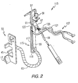
- the voltage sensing circuit 113 for sensing the voltage across the bimetal 55 which is representative of the current flowing through the circuit breaker 1 includes a first conductor in the form of a sense bar 115.
- the sense bar 115 has a main section 117 and a terminal section 119 extending transversely from one end of the main section.
- the terminal section 119 is affixed to the free end of the bimetal 55 such as by welding so that the main section 117 extends generally beside the bimetal toward the fixed end of the bimetal.
- the first conductor then further includes an insulated wire 121 connected to the free end 123 of the sense bar.
- the voltage sensing circuit 113 also includes a second conductor in the form of an insulated wire 125 which is affixed to the second end of the bimetal 55.
- the second conductor 125 is secured to the support conductor 57.
- the support conductor 57 has a much lower resistance than the bimetal, so that the insulated wire 125 senses the voltage at the fixed end of the bimetal.
- the two insulated wires 121 and 125 are then twisted to form a twisted pair 127 leading to the printed circuit board 105.
Landscapes
- Engineering & Computer Science (AREA)
- Power Engineering (AREA)
- Breakers (AREA)
Abstract
Description
Claims (10)
- A circuit breaker (1) for protecting an electrical system, said circuit breaker comprising:separable contacts (13) connected in series with said electrical system;an operating mechanism (18) opening said separable contacts (13) when actuated;an overcurrent trip device (53) including a bimetal (55) having first and second ends connected in series with said separable contacts (13) and being responsive to selected overcurrent conditions in said electrical system for actuating said operating mechanism (18); anda voltage sensing circuit (113) including a first conductor (115, 121) and a second conductor (125) connected to said first and second ends of said bimetal (55), respectively, to sense a sensed voltage across said bimetal (55) representative of current flowing through said bimetal, said first conductor (115, 121) comprising a sense bar (115) joined to said bimetal (55) adjacent to said first end and extending generally beside said bimetal (55) toward said second end; andmeans (103) responsive to said sensed voltage representative of current flowing through said bimetal (55).
- The circuit breaker (1) of Claim 1 wherein said second end of said bimetal is fixed and said first end is free, and wherein said sense bar (115) moves with said free, first end of said bimetal (55).
- The circuit breaker (1) of Claim 2 wherein said second conductor (125) comprises an insulated wire, said sense bar (115) extends beside said bimetal (55) substantially to said second end of said bimetal and terminates in a free end (123), and said first conductor further includes another insulated wire (121) connected to said free end (123) of said sense bar (115) and routed to said response means (103) in close proximity to said insulated wire (125).
- The circuit breaker (1) of Claim 3 wherein said insulated wire (125) and said another insulated wire (121) are twisted about one another to form a twisted pair of wires (127).
- The circuit breaker (1) of Claim 4 wherein said sense bar (115) has a main section (117) extending generally beside said bimetal (55) and a terminal section (119) extending generally transversely from said main section (117) to said bimetal (55) adjacent said first end of said bimetal.
- The circuit breaker (1) of Claim 5 wherein said response means (103) comprises an arc fault detector actuating said operating mechanism (18) in response to predetermined conditions of said sensed voltage representing current through said bimetal (55) indicative of an arcing fault.
- The circuit breaker (1) of Claim 2 wherein said sense bar (115) has a main section (117) extending generally beside said bimetal (55) and a terminal section (119) extending generally transversely from said main section (117) to said bimetal (55) adjacent said first end of said bimetal.
- The circuit breaker (1) of Claim 1 wherein said second conductor (125) comprises an insulated wire, said sense bar (115) extends beside said bimetal (55) substantially to said second end of said bimetal (55) and terminates in a free end (123), and said first conductor (121) further includes another insulated wire connected to said free end (123) of said sense bar (115) and routed to said response means (103) in close proximity to said insulated wire (125).
- The circuit breaker (1) of Claim 8 wherein said response means (103) comprises an arc fault detector actuating said operating mechanism (18) in response to predetermined conditions of said sensed voltage representing current through said bimetal (55) indicative of an arcing fault.
- The circuit breaker (1) of Claim 9 wherein said sense bar (115) has a main section (117) extending generally beside said bimetal (55) and a terminal section (119) extending generally transversely from said main section to said bimetal (55) adjacent said first end of said bimetal.
Applications Claiming Priority (2)
| Application Number | Priority Date | Filing Date | Title |
|---|---|---|---|
| US955779 | 1997-10-22 | ||
| US08/955,779 US5831509A (en) | 1997-10-22 | 1997-10-22 | Circuit breaker with sense bar to sense current from voltage drop across bimetal |
Publications (2)
| Publication Number | Publication Date |
|---|---|
| EP0920046A2 true EP0920046A2 (en) | 1999-06-02 |
| EP0920046A3 EP0920046A3 (en) | 1999-09-22 |
Family
ID=25497317
Family Applications (1)
| Application Number | Title | Priority Date | Filing Date |
|---|---|---|---|
| EP98120040A Withdrawn EP0920046A3 (en) | 1997-10-22 | 1998-10-22 | Circuit breaker with sense bar to sense current from voltage drop across bimetal |
Country Status (5)
| Country | Link |
|---|---|
| US (1) | US5831509A (en) |
| EP (1) | EP0920046A3 (en) |
| JP (1) | JP4142780B2 (en) |
| AU (1) | AU734225B2 (en) |
| CA (1) | CA2251247C (en) |
Families Citing this family (38)
| Publication number | Priority date | Publication date | Assignee | Title |
|---|---|---|---|---|
| US6232857B1 (en) * | 1999-09-16 | 2001-05-15 | General Electric Company | Arc fault circuit breaker |
| US6487057B1 (en) | 2000-06-13 | 2002-11-26 | Eaton Corporation | Ground fault current interrupter/arc fault current interrupter circuit breaker with fail safe mechanism |
| US6445274B1 (en) * | 2000-11-10 | 2002-09-03 | Eaton Corporation | Circuit interrupter with thermal trip adjustability |
| US6642832B2 (en) * | 2000-12-08 | 2003-11-04 | Texas Instruments Incorporated | ARC responsive thermal circuit breaker |
| US6728085B2 (en) | 2001-05-21 | 2004-04-27 | Eaton Corporation | Circuit breaker with shunt |
| US6717786B2 (en) | 2001-10-30 | 2004-04-06 | The Boeing Company | Automatic voltage source selector for circuit breakers utilizing electronics |
| US6724591B2 (en) | 2001-11-15 | 2004-04-20 | Eaton Corporation | Circuit interrupter employing a mechanism to open a power circuit in response to a resistor body burning open |
| US6545574B1 (en) * | 2001-12-17 | 2003-04-08 | General Electric Company | Arc fault circuit breaker |
| DE102006003124A1 (en) * | 2006-01-23 | 2007-08-02 | Siemens Ag | Method for implementing an improved thermo-mechanical overload protection and associated overload protection device |
| US7518482B2 (en) * | 2006-10-10 | 2009-04-14 | Dennis William Fleege | Trip unit having a plurality of stacked bimetal elements |
| US7397333B2 (en) * | 2006-10-18 | 2008-07-08 | Square D Company | Trip unit having bimetal element located outside the yoke |
| DE102008017472A1 (en) * | 2007-04-28 | 2008-11-06 | Abb Ag | Service switching device |
| KR100905021B1 (en) * | 2007-08-07 | 2009-06-30 | 엘에스산전 주식회사 | Thermal overload tripping device and its trip sensitivity adjustment method |
| KR100881365B1 (en) * | 2007-08-07 | 2009-02-02 | 엘에스산전 주식회사 | How to adjust trip sensitivity of thermal overload protector |
| CN101465247B (en) * | 2007-12-21 | 2012-08-08 | 赵建平 | Mechanism for setting and regulating circuit breaker time-delay current |
| AT509407A1 (en) * | 2008-03-05 | 2011-08-15 | Moeller Gebaeudeautomation Gmbh | SWITCHGEAR |
| US7800478B2 (en) * | 2008-05-30 | 2010-09-21 | Eaton Corporation | Electrical switching apparatus and heater assembly therefor |
| US9349559B2 (en) * | 2009-03-23 | 2016-05-24 | Siemens Industry, Inc. | Low-profile electronic circuit breakers, breaker tripping mechanisms, and systems and methods of using same |
| JP4906881B2 (en) * | 2009-03-27 | 2012-03-28 | 富士電機機器制御株式会社 | Thermal overload relay |
| JP2010232058A (en) * | 2009-03-27 | 2010-10-14 | Fuji Electric Fa Components & Systems Co Ltd | Thermal overload relay |
| JP4706772B2 (en) * | 2009-03-27 | 2011-06-22 | 富士電機機器制御株式会社 | Thermal overload relay |
| US8258898B2 (en) * | 2009-11-16 | 2012-09-04 | Schneider Electric USA, Inc. | Low cost multi-pole circuit breakers with shared components |
| DE102011078636A1 (en) * | 2011-07-05 | 2013-01-10 | Siemens Aktiengesellschaft | Overload release, especially for a circuit breaker |
| DE102012202153B4 (en) * | 2012-02-14 | 2021-09-16 | Siemens Aktiengesellschaft | Thermomagnetic release for small current ranges as well as electrical switching device with it |
| US20140176293A1 (en) * | 2012-12-21 | 2014-06-26 | Schneider Electric USA, Inc. | Mechanical flexible thermal trip unit for miniature circuit breakers |
| CN103903921B (en) * | 2012-12-28 | 2016-08-17 | 施耐德电器工业公司 | Overload protection arrangement and include the thermomagnetic adjustable release device of breaker of this device |
| KR20150044746A (en) * | 2013-10-17 | 2015-04-27 | 엘에스산전 주식회사 | Trip device for curcuit breaker |
| US9287065B1 (en) | 2014-06-11 | 2016-03-15 | Google Inc. | Cooling electrical equipment |
| US20160055985A1 (en) * | 2014-08-25 | 2016-02-25 | Siemens Industry, Inc. | Circuit breakers, circuit breaker line power assemblies, and operational methods |
| US9460880B2 (en) * | 2014-11-25 | 2016-10-04 | Schneider Electric USA, Inc. | Thermal-mechanical flexible overload sensor |
| US10598703B2 (en) | 2015-07-20 | 2020-03-24 | Eaton Intelligent Power Limited | Electric fuse current sensing systems and monitoring methods |
| CN105428167A (en) * | 2015-11-05 | 2016-03-23 | 国网山东省电力公司菏泽供电公司 | Electricity larceny preventive circuit breaker |
| US11143718B2 (en) | 2018-05-31 | 2021-10-12 | Eaton Intelligent Power Limited | Monitoring systems and methods for estimating thermal-mechanical fatigue in an electrical fuse |
| US11289298B2 (en) | 2018-05-31 | 2022-03-29 | Eaton Intelligent Power Limited | Monitoring systems and methods for estimating thermal-mechanical fatigue in an electrical fuse |
| US10984974B2 (en) * | 2018-12-20 | 2021-04-20 | Schneider Electric USA, Inc. | Line side power, double break, switch neutral electronic circuit breaker |
| GB2591796A (en) * | 2020-02-07 | 2021-08-11 | Eaton Intelligent Power Ltd | Circuit breaker and method for operating a circuit breaker |
| CN111816514A (en) * | 2020-07-27 | 2020-10-23 | 浙江创奇电气有限公司 | An intelligent circuit breaker based on bimetal strip for metering and sampling |
| GB2624399A (en) * | 2022-11-16 | 2024-05-22 | Eaton Intelligent Power Ltd | Circuit breaker with current measuring capability |
Family Cites Families (8)
| Publication number | Priority date | Publication date | Assignee | Title |
|---|---|---|---|---|
| NL126952C (en) * | 1960-01-07 | |||
| US4081852A (en) * | 1974-10-03 | 1978-03-28 | Westinghouse Electric Corporation | Ground fault circuit breaker |
| JPH01176621A (en) * | 1987-12-29 | 1989-07-13 | Fuji Electric Co Ltd | Circuit breaker overcurrent trip device |
| US5224006A (en) * | 1991-09-26 | 1993-06-29 | Westinghouse Electric Corp. | Electronic circuit breaker with protection against sputtering arc faults and ground faults |
| US5301083A (en) * | 1991-09-30 | 1994-04-05 | Eaton Corporation | Remote control residential circuit breaker |
| US5459630A (en) * | 1993-09-15 | 1995-10-17 | Eaton Corporation | Self testing circuit breaker ground fault and sputtering arc trip unit |
| US5519561A (en) * | 1994-11-08 | 1996-05-21 | Eaton Corporation | Circuit breaker using bimetal of thermal-magnetic trip to sense current |
| US5706154A (en) * | 1996-10-04 | 1998-01-06 | General Electric Company | Residential circuit breaker with arcing fault detection |
-
1997
- 1997-10-22 US US08/955,779 patent/US5831509A/en not_active Expired - Lifetime
-
1998
- 1998-10-21 CA CA002251247A patent/CA2251247C/en not_active Expired - Fee Related
- 1998-10-21 AU AU89418/98A patent/AU734225B2/en not_active Ceased
- 1998-10-21 JP JP31982598A patent/JP4142780B2/en not_active Expired - Fee Related
- 1998-10-22 EP EP98120040A patent/EP0920046A3/en not_active Withdrawn
Also Published As
| Publication number | Publication date |
|---|---|
| CA2251247C (en) | 2007-09-11 |
| EP0920046A3 (en) | 1999-09-22 |
| JPH11213848A (en) | 1999-08-06 |
| US5831509A (en) | 1998-11-03 |
| JP4142780B2 (en) | 2008-09-03 |
| CA2251247A1 (en) | 1999-04-22 |
| AU734225B2 (en) | 2001-06-07 |
| AU8941898A (en) | 1999-05-13 |
Similar Documents
| Publication | Publication Date | Title |
|---|---|---|
| CA2251247C (en) | Circuit breaker with sense bar to sense current from voltage drop across bimetal | |
| US6239677B1 (en) | Circuit breaker thermal magnetic trip unit | |
| US5293522A (en) | Ground fault circuit breaker with test spring/contacts directly mounted to test circuit of printed circuit board | |
| US6477022B1 (en) | Ground fault of arc fault circuit breaker employing first and second separable contacts and plural actuating mechanisms | |
| US6482048B1 (en) | Automated assembly methods for miniature circuit breakers with wire attachment clamps | |
| US6225883B1 (en) | Circuit breaker with latch and toggle mechanism operating in perpendicular planes | |
| US20050269195A1 (en) | Circuit breaker | |
| US3970975A (en) | Ground fault circuit breaker with ground fault trip indicator | |
| US6487057B1 (en) | Ground fault current interrupter/arc fault current interrupter circuit breaker with fail safe mechanism | |
| CA2288467A1 (en) | Circuit breaker with visible trip indicator | |
| US6307453B1 (en) | Circuit breaker with instantaneous trip provided by main conductor routed through magnetic circuit of electronic trip motor | |
| CA2899773C (en) | Bimetal and magnetic armature providing an arc splatter resistant offset therebetween, and circuit breaker including the same | |
| US4090156A (en) | Circuit breaker having solid state and thermal-magnetic trip means | |
| US6788174B1 (en) | Adjustable magnetic trip unit and a circuit breaker incorporating the same | |
| US5565828A (en) | Circuit breaker | |
| US3745414A (en) | Ground fault circuit interrupter | |
| US4064469A (en) | Interchangeable solid state and thermal-magnetic trip units | |
| US4038618A (en) | Circuit breaker having thermal and solid state trip means | |
| WO2002082486A2 (en) | Circuit breaker thermal magnetic trip unit | |
| US6917267B2 (en) | Non-conductive barrier for separating a circuit breaker trip spring and cradle | |
| US8035467B2 (en) | Add-on trip module for multi-pole circuit breaker | |
| US3506941A (en) | Thermal tripping device for circuit breaker | |
| US5999385A (en) | Ground fault circuit breaker | |
| US6850134B2 (en) | Circuit breaker operating mechanism with a metal cradle pivot | |
| PL200691B1 (en) | CIRCUIT BREAKER THERMAL MAGNETIC TRIP UNIT and a circuit breaker comprising said unit and also a VISUAL SIGNALLING |
Legal Events
| Date | Code | Title | Description |
|---|---|---|---|
| PUAI | Public reference made under article 153(3) epc to a published international application that has entered the european phase |
Free format text: ORIGINAL CODE: 0009012 |
|
| AK | Designated contracting states |
Kind code of ref document: A2 Designated state(s): DE FR GB IT |
|
| AX | Request for extension of the european patent |
Free format text: AL;LT;LV;MK;RO;SI |
|
| PUAL | Search report despatched |
Free format text: ORIGINAL CODE: 0009013 |
|
| AK | Designated contracting states |
Kind code of ref document: A3 Designated state(s): AT BE CH CY DE DK ES FI FR GB GR IE IT LI LU MC NL PT SE |
|
| AX | Request for extension of the european patent |
Free format text: AL;LT;LV;MK;RO;SI |
|
| 17P | Request for examination filed |
Effective date: 20000322 |
|
| AKX | Designation fees paid |
Free format text: DE FR GB IT |
|
| STAA | Information on the status of an ep patent application or granted ep patent |
Free format text: STATUS: THE APPLICATION HAS BEEN WITHDRAWN |
|
| 18W | Application withdrawn |
Effective date: 20040824 |