EP0919197B1 - Device for trans myocardial cryo revascularization - Google Patents
Device for trans myocardial cryo revascularization Download PDFInfo
- Publication number
- EP0919197B1 EP0919197B1 EP98204029A EP98204029A EP0919197B1 EP 0919197 B1 EP0919197 B1 EP 0919197B1 EP 98204029 A EP98204029 A EP 98204029A EP 98204029 A EP98204029 A EP 98204029A EP 0919197 B1 EP0919197 B1 EP 0919197B1
- Authority
- EP
- European Patent Office
- Prior art keywords
- passageway
- gas
- operating member
- high pressure
- operating
- Prior art date
- Legal status (The legal status is an assumption and is not a legal conclusion. Google has not performed a legal analysis and makes no representation as to the accuracy of the status listed.)
- Expired - Lifetime
Links
- 230000002107 myocardial effect Effects 0.000 title description 25
- 230000000250 revascularization Effects 0.000 title description 15
- 239000007789 gas Substances 0.000 claims description 56
- 238000002681 cryosurgery Methods 0.000 claims description 22
- XKRFYHLGVUSROY-UHFFFAOYSA-N Argon Chemical compound [Ar] XKRFYHLGVUSROY-UHFFFAOYSA-N 0.000 claims description 10
- 229910052786 argon Inorganic materials 0.000 claims description 5
- 239000001307 helium Substances 0.000 claims description 5
- 229910052734 helium Inorganic materials 0.000 claims description 5
- SWQJXJOGLNCZEY-UHFFFAOYSA-N helium atom Chemical compound [He] SWQJXJOGLNCZEY-UHFFFAOYSA-N 0.000 claims description 5
- IJGRMHOSHXDMSA-UHFFFAOYSA-N Atomic nitrogen Chemical compound N#N IJGRMHOSHXDMSA-UHFFFAOYSA-N 0.000 claims description 4
- 238000004891 communication Methods 0.000 claims description 3
- 229910052743 krypton Inorganic materials 0.000 claims description 2
- DNNSSWSSYDEUBZ-UHFFFAOYSA-N krypton atom Chemical compound [Kr] DNNSSWSSYDEUBZ-UHFFFAOYSA-N 0.000 claims description 2
- 229910052757 nitrogen Inorganic materials 0.000 claims description 2
- 229910052724 xenon Inorganic materials 0.000 claims description 2
- FHNFHKCVQCLJFQ-UHFFFAOYSA-N xenon atom Chemical compound [Xe] FHNFHKCVQCLJFQ-UHFFFAOYSA-N 0.000 claims description 2
- 238000000034 method Methods 0.000 description 24
- 238000010438 heat treatment Methods 0.000 description 16
- 238000001816 cooling Methods 0.000 description 12
- 210000004165 myocardium Anatomy 0.000 description 12
- 210000001519 tissue Anatomy 0.000 description 10
- 230000002861 ventricular Effects 0.000 description 9
- 108090000623 proteins and genes Proteins 0.000 description 8
- 230000015572 biosynthetic process Effects 0.000 description 5
- 239000002245 particle Substances 0.000 description 5
- 239000013598 vector Substances 0.000 description 5
- 230000033115 angiogenesis Effects 0.000 description 4
- 210000004204 blood vessel Anatomy 0.000 description 4
- 238000012546 transfer Methods 0.000 description 4
- 206010002329 Aneurysm Diseases 0.000 description 3
- 206010030113 Oedema Diseases 0.000 description 3
- 208000007536 Thrombosis Diseases 0.000 description 3
- 206010073696 Wallerian degeneration Diseases 0.000 description 3
- 230000000740 bleeding effect Effects 0.000 description 3
- 230000008859 change Effects 0.000 description 3
- 230000006378 damage Effects 0.000 description 3
- 239000003102 growth factor Substances 0.000 description 3
- 230000035876 healing Effects 0.000 description 3
- 230000001939 inductive effect Effects 0.000 description 3
- 230000028709 inflammatory response Effects 0.000 description 3
- 208000014674 injury Diseases 0.000 description 3
- 210000004126 nerve fiber Anatomy 0.000 description 3
- 230000010412 perfusion Effects 0.000 description 3
- 102000004169 proteins and genes Human genes 0.000 description 3
- 230000008929 regeneration Effects 0.000 description 3
- 238000011069 regeneration method Methods 0.000 description 3
- 230000008733 trauma Effects 0.000 description 3
- 230000008734 wallerian degeneration Effects 0.000 description 3
- 206010029113 Neovascularisation Diseases 0.000 description 2
- 108010073929 Vascular Endothelial Growth Factor A Proteins 0.000 description 2
- 102000005789 Vascular Endothelial Growth Factors Human genes 0.000 description 2
- 108010019530 Vascular Endothelial Growth Factors Proteins 0.000 description 2
- 210000001367 artery Anatomy 0.000 description 2
- 210000004369 blood Anatomy 0.000 description 2
- 239000008280 blood Substances 0.000 description 2
- 210000004027 cell Anatomy 0.000 description 2
- 230000000694 effects Effects 0.000 description 2
- 238000007710 freezing Methods 0.000 description 2
- 230000008014 freezing Effects 0.000 description 2
- 238000003780 insertion Methods 0.000 description 2
- 230000037431 insertion Effects 0.000 description 2
- 230000003902 lesion Effects 0.000 description 2
- 239000000203 mixture Substances 0.000 description 2
- 239000000523 sample Substances 0.000 description 2
- 231100000241 scar Toxicity 0.000 description 2
- 230000001225 therapeutic effect Effects 0.000 description 2
- 208000032544 Cicatrix Diseases 0.000 description 1
- 206010063560 Excessive granulation tissue Diseases 0.000 description 1
- 102000009123 Fibrin Human genes 0.000 description 1
- 108010073385 Fibrin Proteins 0.000 description 1
- BWGVNKXGVNDBDI-UHFFFAOYSA-N Fibrin monomer Chemical compound CNC(=O)CNC(=O)CN BWGVNKXGVNDBDI-UHFFFAOYSA-N 0.000 description 1
- 229910052689 Holmium Inorganic materials 0.000 description 1
- GQPLMRYTRLFLPF-UHFFFAOYSA-N Nitrous Oxide Chemical compound [O-][N+]#N GQPLMRYTRLFLPF-UHFFFAOYSA-N 0.000 description 1
- 239000003570 air Substances 0.000 description 1
- 230000003444 anaesthetic effect Effects 0.000 description 1
- 230000017531 blood circulation Effects 0.000 description 1
- 239000004020 conductor Substances 0.000 description 1
- 239000000112 cooling gas Substances 0.000 description 1
- 238000004925 denaturation Methods 0.000 description 1
- 230000036425 denaturation Effects 0.000 description 1
- 210000003743 erythrocyte Anatomy 0.000 description 1
- 230000002349 favourable effect Effects 0.000 description 1
- 229950003499 fibrin Drugs 0.000 description 1
- 210000001126 granulation tissue Anatomy 0.000 description 1
- 238000010562 histological examination Methods 0.000 description 1
- KJZYNXUDTRRSPN-UHFFFAOYSA-N holmium atom Chemical compound [Ho] KJZYNXUDTRRSPN-UHFFFAOYSA-N 0.000 description 1
- 238000010348 incorporation Methods 0.000 description 1
- 208000015181 infectious disease Diseases 0.000 description 1
- 230000007774 longterm Effects 0.000 description 1
- 229910052751 metal Inorganic materials 0.000 description 1
- 239000002184 metal Substances 0.000 description 1
- 238000012986 modification Methods 0.000 description 1
- 230000004048 modification Effects 0.000 description 1
- 230000004660 morphological change Effects 0.000 description 1
- 230000000149 penetrating effect Effects 0.000 description 1
- 230000035515 penetration Effects 0.000 description 1
- 230000008569 process Effects 0.000 description 1
- 230000002035 prolonged effect Effects 0.000 description 1
- 230000004044 response Effects 0.000 description 1
- 230000037387 scars Effects 0.000 description 1
- TXEYQDLBPFQVAA-UHFFFAOYSA-N tetrafluoromethane Chemical compound FC(F)(F)F TXEYQDLBPFQVAA-UHFFFAOYSA-N 0.000 description 1
- 231100000419 toxicity Toxicity 0.000 description 1
- 230000001988 toxicity Effects 0.000 description 1
Images

Classifications
-
- A—HUMAN NECESSITIES
- A61—MEDICAL OR VETERINARY SCIENCE; HYGIENE
- A61B—DIAGNOSIS; SURGERY; IDENTIFICATION
- A61B18/00—Surgical instruments, devices or methods for transferring non-mechanical forms of energy to or from the body
- A61B18/02—Surgical instruments, devices or methods for transferring non-mechanical forms of energy to or from the body by cooling, e.g. cryogenic techniques
-
- A—HUMAN NECESSITIES
- A61—MEDICAL OR VETERINARY SCIENCE; HYGIENE
- A61B—DIAGNOSIS; SURGERY; IDENTIFICATION
- A61B17/00—Surgical instruments, devices or methods
- A61B17/00234—Surgical instruments, devices or methods for minimally invasive surgery
- A61B2017/00238—Type of minimally invasive operation
- A61B2017/00243—Type of minimally invasive operation cardiac
-
- A—HUMAN NECESSITIES
- A61—MEDICAL OR VETERINARY SCIENCE; HYGIENE
- A61B—DIAGNOSIS; SURGERY; IDENTIFICATION
- A61B17/00—Surgical instruments, devices or methods
- A61B17/00234—Surgical instruments, devices or methods for minimally invasive surgery
- A61B2017/00238—Type of minimally invasive operation
- A61B2017/00243—Type of minimally invasive operation cardiac
- A61B2017/00247—Making holes in the wall of the heart, e.g. laser Myocardial revascularization
-
- A—HUMAN NECESSITIES
- A61—MEDICAL OR VETERINARY SCIENCE; HYGIENE
- A61B—DIAGNOSIS; SURGERY; IDENTIFICATION
- A61B18/00—Surgical instruments, devices or methods for transferring non-mechanical forms of energy to or from the body
- A61B2018/00315—Surgical instruments, devices or methods for transferring non-mechanical forms of energy to or from the body for treatment of particular body parts
- A61B2018/00345—Vascular system
- A61B2018/00351—Heart
- A61B2018/00392—Transmyocardial revascularisation
-
- A—HUMAN NECESSITIES
- A61—MEDICAL OR VETERINARY SCIENCE; HYGIENE
- A61B—DIAGNOSIS; SURGERY; IDENTIFICATION
- A61B18/00—Surgical instruments, devices or methods for transferring non-mechanical forms of energy to or from the body
- A61B18/02—Surgical instruments, devices or methods for transferring non-mechanical forms of energy to or from the body by cooling, e.g. cryogenic techniques
- A61B2018/0231—Characteristics of handpieces or probes
- A61B2018/0262—Characteristics of handpieces or probes using a circulating cryogenic fluid
- A61B2018/0268—Characteristics of handpieces or probes using a circulating cryogenic fluid with restriction of flow
- A61B2018/0281—Characteristics of handpieces or probes using a circulating cryogenic fluid with restriction of flow using a tortuous path, e.g. formed by fins or ribs
- A61B2018/0287—Characteristics of handpieces or probes using a circulating cryogenic fluid with restriction of flow using a tortuous path, e.g. formed by fins or ribs the fluid flowing through a long thin tube with spiral shape
-
- F—MECHANICAL ENGINEERING; LIGHTING; HEATING; WEAPONS; BLASTING
- F25—REFRIGERATION OR COOLING; COMBINED HEATING AND REFRIGERATION SYSTEMS; HEAT PUMP SYSTEMS; MANUFACTURE OR STORAGE OF ICE; LIQUEFACTION SOLIDIFICATION OF GASES
- F25B—REFRIGERATION MACHINES, PLANTS OR SYSTEMS; COMBINED HEATING AND REFRIGERATION SYSTEMS; HEAT PUMP SYSTEMS
- F25B2309/00—Gas cycle refrigeration machines
- F25B2309/02—Gas cycle refrigeration machines using the Joule-Thompson effect
- F25B2309/021—Gas cycle refrigeration machines using the Joule-Thompson effect with a cryosurgical probe tip having a specific construction
Definitions
- the present invention relates to a device for trans myocardial cryo revascularization. More particularly, the present invention relates to a device for conducting trans myocardial revascularization by means of a cryosurgery device. Further, the present invention relates to a cryosurgery device including a plurality of Joule-Thomson heat exchangers which enables to effectively conduct such revascularization procedure.
- Trans myocardial revascularization (TMR) procedures including the formation of transmyocardial channels extending from the epicardium to the left ventricular cavity are well known in the art. Such TMR procedures are currently performed by using CO 2 laser or Holmium:YAG laser and are generally known as TMLR procedures.
- TMLR channels provide significant myocardial perfusion by allowing blood to flow therethrough from the left ventricular chamber into the myocardium.
- TMLR trans myocardial laser revascularization
- the healing of the laser induced myocardial burns involves the formation of scar tissue accompanied by neovascularization, which neovascularization may explain the long term therapeutic effect of such TMLR method.
- cryosurgery method and device for trans myocardial cryo revascularization which enable to form durable transmyocardial channels without causing considerable trauma to the myocardial tissue.
- Cryosurgery devices including a Joule-Thomson heat exchanger for providing a surface having a fast changing temperature are disclosed in U.S. Pat. Nos. 5,522,870; 5,540,062; and 5,603,221.
- none of these inventions provides a plurality of cooling and/or heating chambers for effectively pre-cooling and/or pre-heating the incoming gas before it communicates with the operating tip.
- none of these inventions provides a plurality of Joule-Thomson heat exchangers for efficiently and rapidly changing the temperature of gas within such chambers so as to efficiently and rapidly change the temperature of the operating tip.
- Document GB-A-2 283 678 discloses a cryosurgery device according to the preamble of claim 1.
- cryosurgery device having a plurality of cooling and/or heating chambers for effectively pre-cooling and/or pre-heating the incoming gas before it communicates with the operating tip.
- Such a device which includes a plurality of Joule-Thomson heat exchangers for efficiently and rapidly changing the temperature of gas within such chambers so as to efficiently and rapidly change the temperature of the operating tip.
- a cryosurgery device comprising:(a) an operating member having an operating surface and a hollow; and a housing member connected to the operating member; (b) a first passageway extending along the housing member and a portion of the operating member for providing high pressure gas to the operating member, the first passageway including a primary heat exchanging element having a primary orifice located on the first passageway for enabling expansion of gas within the hollow of the operating member, thereby providing a desired temperature to the surface of the operating member; (c) a second passageway extending through the length of the housing member for evacuating gas from the operating tip to atmosphere; (d) a third passageway extending along a portion of at least one of the housing member and the operating member, the third passageway being in heat-exchange communication with the first passageway, the third passageway including a secondary heat exchanging element for providing a desired temperature to gas flowing through the first passageway.
- a portion of the first passageway is enclosed within the third passageway, and the secondary heat exchanging element includes a secondary orifice located on the first passageway for enabling expansion of gas within the third passageway.
- the device comprises a fourth passageway enclosed by at least a portion of the third passageway, the fourth passageway for providing high pressure gas to a selected portion of the device.
- the secondary heat exchanging element preferably includes a secondary orifice located on the fourth passageway for enabling expansion of gas into the third passageway.
- the first passageway provides a first high pressure gas and the fourth passageway provides a second high pressure gas.
- the fourth passageway may extend along the housing member and a portion of the operating member, and may further include a tertiary orifice for enabling expansion of the second high pressure gas within the hollow of the operating member.
- the first passageway and the fourth passageway may include a plurality of orifices located along their length.
- a method of operating the device according to the invention further comprises: providing a high pressure gas to a secondary portion of the operating device and creating a secondary cryogenic pool at the secondary portion so as to precool the high pressure gas provided to the primary portion of the device.
- the operating tip is inserted through the epicardium into the myocardium of a patient.
- the operating device is substantially flexible and the operating tip is inserted through an artery into a ventricular chamber of the patient, preferably by means of a catheter, so as to form channels extending from the ventricular chamber into the patient's myocardium.
- the method further comprises: providing a second high pressure gas to the primary portion of the operating device for heating the operating tip so as to prevent sticking of the tip to the myocardial tissue.
- a second high pressure gas may be also provided to the secondary portion of the device so as to heat the gas provided to the primary portion of the device.
- the present invention successfully addresses the shortcomings of the presently known configurations by providing cryosurgery method and device for trans myocardial cryo revascutarization which enable to form durable transmyocardial channels without causing considerable trauma to the myocardial tissue.
- the present invention addresses the shortcomings of the presently known configurations by providing such device which enables to minimize bleeding, and to substantially eliminate the risk of thrombosis, aneurysms or rupture of major blood vessels.
- such device enables to minimize edema and inflammatory response, do not completely denature proteins, and enable regeneration of nerve fibers following Wallerian degeneration.
- the present invention addresses the shortcomings of the presently known configurations by providing such device which enables to predetermine the location, shape and size of a lesion, thereby minimizing damage to the surrounding area.
- the present invention addresses the shortcomings of the presently known configurations by providing a cryosurgery device having a plurality of cooling and/or heating chambers for effectively pre-cooling and/or pre-heating the incoming gas before it communicates with the operating tip. Further, the present invention addresses the shortcomings of the presently known configurations by providing a cryosurgery device having a plurality of Joule-Thomson heat exchangers for efficiently and rapidly changing the temperature of gas within such chambers so as to efficiently and rapidly change the temperature of the operating tip.
- the present invention is a device for trans myocardial cryo revascularization. Specifically, according to the present invention there is provided a device for conducting trans myocardial revascularization by means of a cryosurgery device. Further, according to the present invention there is provided a cryosurgery device including a plurality of Joule-Thomson heat exchangers which enables to effectively conduct such revascularization procedure.
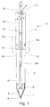
- FIG. 1 illustrates a preferred embodiment of a cryosurgery device according to the present invention.
- a cryosurgery device 2 preferably includes elongated housing 3 having a pointed operating tip 4 for penetrating through the epicardium and myocardium of a patient into a ventricular chamber.
- Operating tip 4 features a shape of a needle element for allowing a surgeon to effectively and accurately determine the site of insertion of operating tip 4 into the epicardium, and to appropriately directing the device through the patient's myocardium according to a desired and predetermined path.
- Operating tip 4 may feature various shapes and sizes so as to enable the surgeon to form transmyocardial channels of a predetermined diameter and shape, thereby minimizing damage to surrounding areas.
- operating tip 4 is connected to elongated housing 3 by means of an elongated member 5 substantially thin in cross section for allowing insertion thereof through the patient's myocardium.
- operating tip 4 is substantially elongated so as to allow effective cryoablation of tissues surrounding the tip when the tip penetrates the myocardium.
- Operating tip 4 and elongated member 5 preferably feature a diameter of between about 0.8 mm and about 1.6 mm so as to allow the formation of transmyocardial channels of substantially small diameter.
- Operating tip 4 preferably features a length of between about 2.5 cm and bout 3.5 cm for enabling effective cryoablation across the myocardium.
- a cryosurgery device may feature any diameter and length adapted for carrying out cryosurgical procedures other than trans myocardial revascularization.
- operating tip 4 and elongated member 5 may feature a diameter between about 0.5 mm and about 3 mm.
- a device includes a first passageway 10 extending along the length of the device for providing gas of high pressure to a heat exchanger located at operating tip 4, and a second passageway 16 for evacuating gas from the operating tip to atmosphere.
- First passageway 10 is preferably in the form of a substantially thin tubular element extending along elongated housing 3, elongated member 5, and a portion of operating tip 4.
- the portion of first passageway 10 extending along elongated housing 3 is preferably in the form of a spiral tube 14a wrapped around second passageway 16.
- the portion of first passageway 10 extending along elongated member 5 and portion of operating tip 4 is preferably in the form of a straight tube 14b received within second passageway 16. Further as shown in the figure, tube 14b preferably penetrates into second passageway, 16 substantially adjacent the connection of elongated member 5 and housing 3.
- elongated housing 3 preferably includes a third passageway 20 enclosing first and second passageways 10 and 16, which third passageway forming a heat exchanging chamber for precooling or preheating gas flowing within spiral tube 14a before it arrives to operating tip 4.
- Third passageway 20 preferably merges with second passageway 16 at the upper end of elongated housing 3 to form a common passageway 22 for releasing gas to atmosphere.
- the various passageways of the device are enclosed by an insulating chamber 24 extending along housing 3 and elongated member 5.
- first passageway 10 preferably includes a plurality of orifices for passage of high pressure gas therethrough so as to cool or heat selective portions of the device, depending on the type of gas used.
- Gases which may be used for cooling include argon, nitrogen, air, krypton, CF 4 , xenon, N 2 O, or any mixture of gases.
- Gases which may be used for heating include helium or any mixture of gases.
- a primary Joule Thomson heat exchanger is located at operating tip 4, which heat exchanger including: an orifice 6 located preferably at the end of straight tube 14b, and a chamber 7 defined by the inner walls of tip 4.
- a high pressure gas such as argon expands through orifice 6 it liquifies so as to form a cryogenic pool within chamber 7 of operating tip 4, which cryogenic pool effectively cools surface 8 of operating tip 4.
- Surface 8 is preferably made of a heat conducting material such as metal for effectively freezing the myocardial tissue so as to produce the desired cryoablation effect.
- a high pressure gas such as helium expands through orifice 6 it heats chamber 7 of operating tip 4, thereby heating surface 8 of the operating tip.
- Such heating of the operating tip may be used for preventing sticking of the device to the myocardial tissue.
- a device preferably includes a plurality of Joule Thomson heat exchangers for effectively precooling or preheating the gas flowing within first passageway 10.
- the device includes a secondary Joule Thomson heat exchanger located within housing 3, including: an orifice 18 located preferably at the lower end of spiral tube 14, and a chamber 21 defined by the inner walls of passageway 20.
- a high pressure gas such as argon expands through orifice 18 it liquifies so as to form a cryogenic pool within chamber 21, which cryogenic pool effectively cools passageway 20, thereby precooling the gas flowing within spiral tube 14a.
- a high pressure gas such as helium expands through orifice 18 it heats chamber 21 and passageway 20, thereby effectively preheating the gas flowing within spiral tube 14a.
- gas flowing through spiral tube 14a is effectively pre-cooled or pre-heated by exchanging heat with third passageway 20. Furthermore, the gas flowing through spiral tube 14a and strait tube 14b exchanges heat with second passageway 16 which contains cooled (or heated) gas coming from operating tip 4.
- a cryosurgery device enables to effectively and quickly produce the desired freezing effect and to quickly inverse from cooling to heating so as to prevent sticking of the operating tip to the tissue.
- first passageway 10 may include a plurality of orifices located along spiral tube 14a and strait tube 14b.
- a device according to the present invention may include a plurality of Joule Thomson heat exchangers for cooling or heating selected portions of the device, wherein each of the heat exchangers includes plurality of orifices.
- the device may include a plurality of entering passageways of distinct lengths, each passageway for providing gas to a selected portion of the device.
- the device may include two entering passageways, 10 and 11, wherein passageway 10 ends nearby operating tip 4 and provides high pressure gas so as to selectively cool or heat chamber 7 and operating tip 4, and wherein passageway 11 ends at housing 3 and provides high pressure gas so as to selectively cool or heat chamber 21 and third passageway 20.
- passageway 10 includes a spiral tube portion 14a extending along housing 3 and a straight tube portion 14b extending along elongated member 5 and having an orifice 6 located at its end.
- Passageway 11 preferably includes a spiral tube portion 15a extending along housing 3 and having an orifice 19 located at its end.
- the device includes two entering passageways extending through the length or the device and ending nearby the operating tip, wherein one passageway provides a cooling gas such as argon and the other passageway provides a heating gas such as helium, and wherein each of the passageways includes a primary orifice for cooling or heating chamber 7 and operating tip 4, and a secondary orifice for cooling or heating chamber 21 and passageway 20.
- the various portions of the cryosurgery device may be substantially rigid or substantially flexible.
- a flexible elongated cryosurgery probe may be inserted retrogradely through an artery into a ventricular chamber, preferably by means of a catheter, so as to form transmyocardial channels extending from the ventricular chamber to a predetermined depth within the myocardium.
- Such an embodiment enables to perform minimally invasive trans myocardial revascularization procedures in a closed chest fashion and eliminates the need to perform an open lateral thoracotomy.
- the incorporation of video-assisted thoracoscopy allows to continuously monitor the trans myocardial revascularization procedure so as to accurately direct the flexible probe to predetermined sites at the patient's epicardium and to control the depth of penetration into the myocardium.
- an endoscope and/or a miniature video camera is connected to housing 3 of the cryosurgery device by means of a connector element.
- the device according to the present invention enables to create durable transmyocardial channels without causing considerable trauma to the myocardial tissue due to their anesthetic quality.
- such device enables to minimize bleeding, and to substantially eliminate the risk of thrombosis, aneurysms or rupture ot major blood vessels. Further, such method and device enable to minimize protein denaturation, edema formation and inflammatory response. Further, such method and device enable regeneration of nerve fibers following Wallerian degeneration.
- angiogenesis inducing factors may be incorporated to the cryogenic device or independently injected into the drilled channels so as to stimulate formation of new blood vessels.
- Such angiogenesis inducing factors may include growth factors such as VEGF (Vascular Endothelial Growth Factor).
- the angiogenesis inducing factors include vectors carrying genes encoding for specific growth factors so as to allow slow release of such growth factors for a predetermined period of time.
- Trans myocardial cryo revascularization device enables to appropriately regulate the angiogenesis process by ensuring effective gene transfer. It is well know in the art that the effectiveness of gene transfer depends on the ratio of infecting particles to infected cells, which ratio referred to as multiplicity of infection (m.o.i.), wherein low m.o.i. results in ineffective gene transfer and high m.o.i. results in toxicity and cells death. Method and device according to the present invention enable to precisely predict the dimensions of the trans myocardial channels, thereby enabling to accurately determine the amount of infecting vector particles which would produce a desired therapeutic effect.
- multiplicity of infection m.o.i.
- Transmyocardial cryo revascularization provides favorable conditions for gene transfer since it provides a low temperature environment for introducing the vector particles, thereby enabling to maintain the infectivity of the vector particles for substantially extended period of time, unlike the TMLR method which creates substantially hot environment.
- blood from the ventricular cavity immediately freezes at the endocardial surface, thereby enabling substantially prolonged communication between the vector particles and the myocardial tissue, unlike the TMLR method wherein ventricular blood flows through the myocardium to the epicardial surface.
Landscapes
- Health & Medical Sciences (AREA)
- Surgery (AREA)
- Life Sciences & Earth Sciences (AREA)
- Nuclear Medicine, Radiotherapy & Molecular Imaging (AREA)
- Medical Informatics (AREA)
- General Health & Medical Sciences (AREA)
- Biomedical Technology (AREA)
- Heart & Thoracic Surgery (AREA)
- Otolaryngology (AREA)
- Molecular Biology (AREA)
- Animal Behavior & Ethology (AREA)
- Engineering & Computer Science (AREA)
- Public Health (AREA)
- Veterinary Medicine (AREA)
- Surgical Instruments (AREA)
- Thermotherapy And Cooling Therapy Devices (AREA)
- Media Introduction/Drainage Providing Device (AREA)
- Prostheses (AREA)
Description
- The present invention relates to a device for trans myocardial cryo revascularization. More particularly, the present invention relates to a device for conducting trans myocardial revascularization by means of a cryosurgery device. Further, the present invention relates to a cryosurgery device including a plurality of Joule-Thomson heat exchangers which enables to effectively conduct such revascularization procedure.
- Trans myocardial revascularization (TMR) procedures including the formation of transmyocardial channels extending from the epicardium to the left ventricular cavity are well known in the art. Such TMR procedures are currently performed by using CO2 laser or Holmium:YAG laser and are generally known as TMLR procedures.
- Various studies have been conducted so as to determine whether such TMLR channels provide significant myocardial perfusion by allowing blood to flow therethrough from the left ventricular chamber into the myocardium.
- Histological examinations have revealed that such channels do not provide significant myocardial perfusion. Rather, the channels undergo significant morphologic changes within two weeks, wherein epicardial and endocardial scars appear at the ends of the channels, and wherein the channels are invaded with granulation tissue containing capillaries and lacunar spaces filled with fibrin and red blood cells. After two weeks, the channels are obscured with massive healing response induced by the infraction so that no definitive channels are identified within the healing myocardium.
- Thus, it seems that the TMLR (trans myocardial laser revascularization) method fails to provide durable transmyocardial channels and thereby fails to provide significant myocardial perfusion therethrough.
- Rather, the healing of the laser induced myocardial burns involves the formation of scar tissue accompanied by neovascularization, which neovascularization may explain the long term therapeutic effect of such TMLR method.
- There is thus a widely recognized need for, and it would be highly advantageous to have, cryosurgery method and device for trans myocardial cryo revascularization which enable to form durable transmyocardial channels without causing considerable trauma to the myocardial tissue.
- It would be further advantageous to have such method and device which enable to minimize bleeding, and to substantially eliminate the risk of thrombosis, aneurysms or rupture of major blood vessels.
- It would be further advantageous to have such method and device which enable to minimize edema and inflammatory response. Further, it would be advantageous to have such method and device which do not completely denature proteins and which enable regeneration of nerve fibers following Wallerian degeneration.
- It would be further advantageous to have such method and device which enable to predetermine the location, shape and size of a lesion, thereby minimizing damage to the surrounding area.
- Cryosurgery devices including a Joule-Thomson heat exchanger for providing a surface having a fast changing temperature are disclosed in U.S. Pat. Nos. 5,522,870; 5,540,062; and 5,603,221.
- However, none of these inventions provides a plurality of cooling and/or heating chambers for effectively pre-cooling and/or pre-heating the incoming gas before it communicates with the operating tip.
- Further, none of these inventions provides a plurality of Joule-Thomson heat exchangers for efficiently and rapidly changing the temperature of gas within such chambers so as to efficiently and rapidly change the temperature of the operating tip.
- Document GB-A-2 283 678 discloses a cryosurgery device according to the preamble of claim 1.
- There is thus a widely recognized need for, and it would be highly advantageous to have, a cryosurgery device having a plurality of cooling and/or heating chambers for effectively pre-cooling and/or pre-heating the incoming gas before it communicates with the operating tip.
- It would be further advantageous to have such a device which includes a plurality of Joule-Thomson heat exchangers for efficiently and rapidly changing the temperature of gas within such chambers so as to efficiently and rapidly change the temperature of the operating tip.
- According to the present invention there is provided a cryosurgery device, comprising:(a) an operating member having an operating surface and a hollow; and a housing member connected to the operating member; (b) a first passageway extending along the housing member and a portion of the operating member for providing high pressure gas to the operating member, the first passageway including a primary heat exchanging element having a primary orifice located on the first passageway for enabling expansion of gas within the hollow of the operating member, thereby providing a desired temperature to the surface of the operating member; (c) a second passageway extending through the length of the housing member for evacuating gas from the operating tip to atmosphere; (d) a third passageway extending along a portion of at least one of the housing member and the operating member, the third passageway being in heat-exchange communication with the first passageway, the third passageway including a secondary heat exchanging element for providing a desired temperature to gas flowing through the first passageway.
- According to further features in preferred embodiments of the invention described below, a portion of the first passageway is enclosed within the third passageway, and the secondary heat exchanging element includes a secondary orifice located on the first passageway for enabling expansion of gas within the third passageway.
- According to the invention, the device comprises a fourth passageway enclosed by at least a portion of the third passageway, the fourth passageway for providing high pressure gas to a selected portion of the device. The secondary heat exchanging element preferably includes a secondary orifice located on the fourth passageway for enabling expansion of gas into the third passageway.
- According to the invention, the first passageway provides a first high pressure gas and the fourth passageway provides a second high pressure gas.
- The fourth passageway may extend along the housing member and a portion of the operating member, and may further include a tertiary orifice for enabling expansion of the second high pressure gas within the hollow of the operating member.
- The first passageway and the fourth passageway may include a plurality of orifices located along their length.
- A method of operating the device according to the invention further comprises: providing a high pressure gas to a secondary portion of the operating device and creating a secondary cryogenic pool at the secondary portion so as to precool the high pressure gas provided to the primary portion of the device.
- Preferably, the operating tip is inserted through the epicardium into the myocardium of a patient. Alternatively, the operating device is substantially flexible and the operating tip is inserted through an artery into a ventricular chamber of the patient, preferably by means of a catheter, so as to form channels extending from the ventricular chamber into the patient's myocardium.
- The method further comprises: providing a second high pressure gas to the primary portion of the operating device for heating the operating tip so as to prevent sticking of the tip to the myocardial tissue. Such second high pressure gas may be also provided to the secondary portion of the device so as to heat the gas provided to the primary portion of the device.
- The present invention successfully addresses the shortcomings of the presently known configurations by providing cryosurgery method and device for trans myocardial cryo revascutarization which enable to form durable transmyocardial channels without causing considerable trauma to the myocardial tissue.
- Specifically, the present invention addresses the shortcomings of the presently known configurations by providing such device which enables to minimize bleeding, and to substantially eliminate the risk of thrombosis, aneurysms or rupture of major blood vessels.
- Further, such device enables to minimize edema and inflammatory response, do not completely denature proteins, and enable regeneration of nerve fibers following Wallerian degeneration.
- Further, the present invention addresses the shortcomings of the presently known configurations by providing such device which enables to predetermine the location, shape and size of a lesion, thereby minimizing damage to the surrounding area.
- Further, the present invention addresses the shortcomings of the presently known configurations by providing a cryosurgery device having a plurality of cooling and/or heating chambers for effectively pre-cooling and/or pre-heating the incoming gas before it communicates with the operating tip. Further, the present invention addresses the shortcomings of the presently known configurations by providing a cryosurgery device having a plurality of Joule-Thomson heat exchangers for efficiently and rapidly changing the temperature of gas within such chambers so as to efficiently and rapidly change the temperature of the operating tip.
- The invention is herein described, by way of example only, with reference to the accompanying drawings, wherein:
- FIG. 1 is a schematic side view, partially in longitudinal section, of a cryosurgery device according to the present invention.
- FIG. 2 is a schematic side view, partially in longitudinal section, of another embodiment of a cryosurgery device according to the present invention.
-
- The present invention is a device for trans myocardial cryo revascularization. Specifically, according to the present invention there is provided a device for conducting trans myocardial revascularization by means of a cryosurgery device. Further, according to the present invention there is provided a cryosurgery device including a plurality of Joule-Thomson heat exchangers which enables to effectively conduct such revascularization procedure.
- The principies and operation of apparatus according to the present invention may be better underwood with reference to the drawings and the accompanying description.
- Referring now to the drawings, FIG. 1 illustrates a preferred embodiment of a cryosurgery device according to the present invention.
- As shown in the figures, a
cryosurgery device 2 according to the present invention preferably includeselongated housing 3 having apointed operating tip 4 for penetrating through the epicardium and myocardium of a patient into a ventricular chamber.Operating tip 4 features a shape of a needle element for allowing a surgeon to effectively and accurately determine the site of insertion ofoperating tip 4 into the epicardium, and to appropriately directing the device through the patient's myocardium according to a desired and predetermined path.Operating tip 4 may feature various shapes and sizes so as to enable the surgeon to form transmyocardial channels of a predetermined diameter and shape, thereby minimizing damage to surrounding areas. - As shown in the figures,
operating tip 4 is connected toelongated housing 3 by means of anelongated member 5 substantially thin in cross section for allowing insertion thereof through the patient's myocardium. According to another embodiment (FIG. 2),operating tip 4 is substantially elongated so as to allow effective cryoablation of tissues surrounding the tip when the tip penetrates the myocardium.Operating tip 4 andelongated member 5 preferably feature a diameter of between about 0.8 mm and about 1.6 mm so as to allow the formation of transmyocardial channels of substantially small diameter.Operating tip 4 preferably features a length of between about 2.5 cm and bout 3.5 cm for enabling effective cryoablation across the myocardium. - A cryosurgery device according to the present invention may feature any diameter and length adapted for carrying out cryosurgical procedures other than trans myocardial revascularization. For example,
operating tip 4 andelongated member 5 may feature a diameter between about 0.5 mm and about 3 mm. - As shown in FIG. 1, a device according to the present invention includes a
first passageway 10 extending along the length of the device for providing gas of high pressure to a heat exchanger located atoperating tip 4, and asecond passageway 16 for evacuating gas from the operating tip to atmosphere.First passageway 10 is preferably in the form of a substantially thin tubular element extending alongelongated housing 3,elongated member 5, and a portion ofoperating tip 4. As shown in the figures, the portion offirst passageway 10 extending alongelongated housing 3 is preferably in the form of aspiral tube 14a wrapped aroundsecond passageway 16. The portion offirst passageway 10 extending alongelongated member 5 and portion ofoperating tip 4 is preferably in the form of astraight tube 14b received withinsecond passageway 16. Further as shown in the figure,tube 14b preferably penetrates into second passageway, 16 substantially adjacent the connection ofelongated member 5 andhousing 3. - Further,
elongated housing 3 preferably includes athird passageway 20 enclosing first andsecond passageways spiral tube 14a before it arrives to operatingtip 4.Third passageway 20 preferably merges withsecond passageway 16 at the upper end ofelongated housing 3 to form acommon passageway 22 for releasing gas to atmosphere. - As shown in the figures, the various passageways of the device are enclosed by an insulating
chamber 24 extending alonghousing 3 andelongated member 5. - Preferably, a device according to the present invention provides effective cooling or heating by using Joule Thomson heat exchangers. Thus,
first passageway 10 preferably includes a plurality of orifices for passage of high pressure gas therethrough so as to cool or heat selective portions of the device, depending on the type of gas used. Gases which may be used for cooling include argon, nitrogen, air, krypton, CF4, xenon, N2O, or any mixture of gases. Gases which may be used for heating include helium or any mixture of gases. - According to the embodiment shown in FIG. 1, a primary Joule Thomson heat exchanger is located at operating
tip 4, which heat exchanger including: anorifice 6 located preferably at the end ofstraight tube 14b, and achamber 7 defined by the inner walls oftip 4. When a high pressure gas such as argon expands throughorifice 6 it liquifies so as to form a cryogenic pool withinchamber 7 ofoperating tip 4, which cryogenic pool effectively coolssurface 8 ofoperating tip 4.Surface 8 is preferably made of a heat conducting material such as metal for effectively freezing the myocardial tissue so as to produce the desired cryoablation effect. When a high pressure gas such as helium expands throughorifice 6 it heatschamber 7 ofoperating tip 4, therebyheating surface 8 of the operating tip. Such heating of the operating tip may be used for preventing sticking of the device to the myocardial tissue. - A device according to the present invention preferably includes a plurality of Joule Thomson heat exchangers for effectively precooling or preheating the gas flowing within
first passageway 10. According to the embodiment shown in FIG. 1, the device includes a secondary Joule Thomson heat exchanger located withinhousing 3, including: anorifice 18 located preferably at the lower end of spiral tube 14, and achamber 21 defined by the inner walls ofpassageway 20. When a high pressure gas such as argon expands throughorifice 18 it liquifies so as to form a cryogenic pool withinchamber 21, which cryogenic pool effectively coolspassageway 20, thereby precooling the gas flowing withinspiral tube 14a. When a high pressure gas such as helium expands throughorifice 18 it heatschamber 21 andpassageway 20, thereby effectively preheating the gas flowing withinspiral tube 14a. - Thus, gas flowing through
spiral tube 14a is effectively pre-cooled or pre-heated by exchanging heat withthird passageway 20. Furthermore, the gas flowing throughspiral tube 14a andstrait tube 14b exchanges heat withsecond passageway 16 which contains cooled (or heated) gas coming from operatingtip 4. - A cryosurgery device according to the present invention enables to effectively and quickly produce the desired freezing effect and to quickly inverse from cooling to heating so as to prevent sticking of the operating tip to the tissue.
- According to another embodiment (not shown),
first passageway 10 may include a plurality of orifices located alongspiral tube 14a andstrait tube 14b. Further, a device according to the present invention may include a plurality of Joule Thomson heat exchangers for cooling or heating selected portions of the device, wherein each of the heat exchangers includes plurality of orifices. - Referring now to FIG. 2, according to another embodiment the device may include a plurality of entering passageways of distinct lengths, each passageway for providing gas to a selected portion of the device. Thus, the device may include two entering passageways, 10 and 11, wherein
passageway 10 endsnearby operating tip 4 and provides high pressure gas so as to selectively cool orheat chamber 7 andoperating tip 4, and whereinpassageway 11 ends athousing 3 and provides high pressure gas so as to selectively cool orheat chamber 21 andthird passageway 20. Preferably,passageway 10 includes aspiral tube portion 14a extending alonghousing 3 and astraight tube portion 14b extending alongelongated member 5 and having anorifice 6 located at its end.Passageway 11 preferably includes aspiral tube portion 15a extending alonghousing 3 and having anorifice 19 located at its end. - According to yet another embodiment (not shown), the device includes two entering passageways extending through the length or the device and ending nearby the operating tip, wherein one passageway provides a cooling gas such as argon and the other passageway provides a heating gas such as helium, and wherein each of the passageways includes a primary orifice for cooling or
heating chamber 7 andoperating tip 4, and a secondary orifice for cooling orheating chamber 21 andpassageway 20. - The various portions of the cryosurgery device may be substantially rigid or substantially flexible.
- According to a preferred embodiment, a flexible elongated cryosurgery probe may be inserted retrogradely through an artery into a ventricular chamber, preferably by means of a catheter, so as to form transmyocardial channels extending from the ventricular chamber to a predetermined depth within the myocardium.
- Such an embodiment enables to perform minimally invasive trans myocardial revascularization procedures in a closed chest fashion and eliminates the need to perform an open lateral thoracotomy.
- According to a preferred embodiment of the invention, the incorporation of video-assisted thoracoscopy allows to continuously monitor the trans myocardial revascularization procedure so as to accurately direct the flexible probe to predetermined sites at the patient's epicardium and to control the depth of penetration into the myocardium. Preferably, an endoscope and/or a miniature video camera is connected to
housing 3 of the cryosurgery device by means of a connector element. - The device according to the present invention enables to create durable transmyocardial channels without causing considerable trauma to the myocardial tissue due to their anesthetic quality.
- Thus, such device enables to minimize bleeding, and to substantially eliminate the risk of thrombosis, aneurysms or rupture ot major blood vessels. Further, such method and device enable to minimize protein denaturation, edema formation and inflammatory response. Further, such method and device enable regeneration of nerve fibers following Wallerian degeneration.
- According to further aspects of the present invention, angiogenesis inducing factors may be incorporated to the cryogenic device or independently injected into the drilled channels so as to stimulate formation of new blood vessels. Such angiogenesis inducing factors may include growth factors such as VEGF (Vascular Endothelial Growth Factor). Preferably, the angiogenesis inducing factors include vectors carrying genes encoding for specific growth factors so as to allow slow release of such growth factors for a predetermined period of time.
- Trans myocardial cryo revascularization device according to the present invention enables to appropriately regulate the angiogenesis process by ensuring effective gene transfer. It is well know in the art that the effectiveness of gene transfer depends on the ratio of infecting particles to infected cells, which ratio referred to as multiplicity of infection (m.o.i.), wherein low m.o.i. results in ineffective gene transfer and high m.o.i. results in toxicity and cells death. Method and device according to the present invention enable to precisely predict the dimensions of the trans myocardial channels, thereby enabling to accurately determine the amount of infecting vector particles which would produce a desired therapeutic effect.
- Transmyocardial cryo revascularization provides favorable conditions for gene transfer since it provides a low temperature environment for introducing the vector particles, thereby enabling to maintain the infectivity of the vector particles for substantially extended period of time, unlike the TMLR method which creates substantially hot environment.
- Further, when using a device according to the present invention, blood from the ventricular cavity immediately freezes at the endocardial surface, thereby enabling substantially prolonged communication between the vector particles and the myocardial tissue, unlike the TMLR method wherein ventricular blood flows through the myocardium to the epicardial surface.
- While the invention has been described with respect to a limited number of embodiments, it will be appreciated that many variations, modifications and other applications of the invention may be made.
Claims (12)
- A cryosurgery device, comprising:wherein said first passageway provides a first high pressure gas and said fourth passageway provides a second high pressure helium gas.(a) an operating member (4) having an operating surface (8) and a hollow (7); and a housing member (3) connected to said operating member;(b) a first passageway (10,14a,14b) extending along said housing member and a portion of said operating member for providing high pressure gas to said operating member, said first passageway including a primary heat exchanging element having a primary orifice (6) located on said first passageway for enabling expansion of said gas within said hollow of said operating member, thereby providing a desired temperature to said surface of said operating member;(c) a second passageway (16) extending through the length of said housing member for evacuating gas from said operating member to atmosphere:(d) a third passageway (20) extending along a portion of at least one of said housing member and operating member, said third passageway being in heat-exchange communication with said first passageway, said third passageway including a secondary heat exchanging element for providing a desired temperature to gas flowing through said first passageway; characterized by:(e) a fourth passageway (11) enclosed by at least a portion of said third passageway, said fourth passageway for providing high pressure gas to a selected portion of said device, and wherein said secondary heat exchanging element includes a secondary orifice (19) located on said fourth passageway to enabling expansion of gas into said third passageway;
- The device of claim 1, wherein a portion of said first passageway is enclosed within said third passageway, and wherein said secondary heat exchanging element includes said secondary orifice (19) located on said first passageway for enabling expansion of gas within said third passageway.
- The device of claim 1, wherein a portion of said first passageway is in the form of a spiral tube (14a) rapped around said second passageway.
- The device of claim 1, wherein a portion (14b) of said first passageway is enclosed by said second passageway.
- The device of claim 1, further including an insulating chamber (24)
- The device of claim 1, wherein said first passageway includes a plurality of orifices located along its length.
- The device of claim 6, wherein at least one of said orifices is for allowing expansion of said high pressure gas within said third passageway.
- The device of claim 1, wherein said high pressure gas is selected from the group consisting of:(a) argon:(b) nitrogen;(c) air;(d) krypton;(e) CF4;(f) xenon; and(g) N2O.
- The device of claim 1, wherein said housing member and said operating member feature an elongated shape.
- The device of claim 9, wherein said operating member features a diameter of between about 0.8 mm and about 1.6 mm.
- The device of claim 1, wherein at least a portion of said device is substantially flexible.
- The device of claim 1, wherein at least a portion of said device is substantially rigid.
Applications Claiming Priority (2)
| Application Number | Priority Date | Filing Date | Title |
|---|---|---|---|
| US08/982,860 US5885276A (en) | 1997-12-02 | 1997-12-02 | Method and device for transmyocardial cryo revascularization |
| US982860 | 1997-12-02 |
Publications (2)
| Publication Number | Publication Date |
|---|---|
| EP0919197A1 EP0919197A1 (en) | 1999-06-02 |
| EP0919197B1 true EP0919197B1 (en) | 2005-02-16 |
Family
ID=25529577
Family Applications (1)
| Application Number | Title | Priority Date | Filing Date |
|---|---|---|---|
| EP98204029A Expired - Lifetime EP0919197B1 (en) | 1997-12-02 | 1998-11-30 | Device for trans myocardial cryo revascularization |
Country Status (5)
| Country | Link |
|---|---|
| US (2) | US5885276A (en) |
| EP (1) | EP0919197B1 (en) |
| JP (1) | JPH11276495A (en) |
| CA (1) | CA2252988C (en) |
| DE (1) | DE69829028T2 (en) |
Cited By (4)
| Publication number | Priority date | Publication date | Assignee | Title |
|---|---|---|---|---|
| US11633224B2 (en) | 2020-02-10 | 2023-04-25 | Icecure Medical Ltd. | Cryogen pump |
| US12215811B2 (en) | 2022-07-18 | 2025-02-04 | Icecure Medical Ltd. | Cryogenic system connector |
| US12426934B2 (en) | 2022-02-28 | 2025-09-30 | Icecure Medical Ltd. | Cryogen flow control |
| US12527613B2 (en) | 2023-09-11 | 2026-01-20 | Icecure Medical Ltd. | Cryoprobe |
Families Citing this family (79)
| Publication number | Priority date | Publication date | Assignee | Title |
|---|---|---|---|---|
| US5800488A (en) * | 1996-07-23 | 1998-09-01 | Endocare, Inc. | Cryoprobe with warming feature |
| US6120520A (en) | 1997-05-27 | 2000-09-19 | Angiotrax, Inc. | Apparatus and methods for stimulating revascularization and/or tissue growth |
| US6051008A (en) | 1996-12-02 | 2000-04-18 | Angiotrax, Inc. | Apparatus having stabilization members for percutaneously performing surgery and methods of use |
| US6102926A (en) | 1996-12-02 | 2000-08-15 | Angiotrax, Inc. | Apparatus for percutaneously performing myocardial revascularization having means for sensing tissue parameters and methods of use |
| US6281175B1 (en) | 1997-09-23 | 2001-08-28 | Scimed Life Systems, Inc. | Medical emulsion for lubrication and delivery of drugs |
| US6251105B1 (en) | 1998-03-31 | 2001-06-26 | Endocare, Inc. | Cryoprobe system |
| US6261304B1 (en) | 1998-09-10 | 2001-07-17 | Percardia, Inc. | Delivery methods for left ventricular conduit |
| ATE238004T1 (en) * | 1999-02-12 | 2003-05-15 | Nikolai Korpan | DEVICE FOR CRYOSURGICAL PROCEDURES, IN PARTICULAR FOR TUMOR TREATMENT |
| US6468271B1 (en) | 1999-02-24 | 2002-10-22 | Scimed Life Systems, Inc. | Device and method for percutaneous myocardial revascularization |
| US6217575B1 (en) | 1999-02-24 | 2001-04-17 | Scimed Life Systems, Inc. | PMR catheter |
| US6546932B1 (en) | 1999-04-05 | 2003-04-15 | Cryocath Technologies Inc. | Cryogenic method and apparatus for promoting angiogenesis |
| US6626899B2 (en) * | 1999-06-25 | 2003-09-30 | Nidus Medical, Llc | Apparatus and methods for treating tissue |
| US6329348B1 (en) | 1999-11-08 | 2001-12-11 | Cornell Research Foundation, Inc. | Method of inducing angiogenesis |
| WO2001037919A2 (en) * | 1999-11-12 | 2001-05-31 | Cryocath Technologies, Inc. | Cryomedical device for promoting angiogenesis |
| US6503246B1 (en) * | 2000-07-05 | 2003-01-07 | Mor Research Applications Ltd. | Cryoprobe and method of treating scars |
| US7686799B2 (en) * | 2000-07-13 | 2010-03-30 | Abbott Cardiovascular Systems Inc. | Deployment system for myocardial cellular material |
| US6706037B2 (en) * | 2000-10-24 | 2004-03-16 | Galil Medical Ltd. | Multiple cryoprobe apparatus and method |
| US20020068929A1 (en) * | 2000-10-24 | 2002-06-06 | Roni Zvuloni | Apparatus and method for compressing a gas, and cryosurgery system and method utilizing same |
| US20020188287A1 (en) * | 2001-05-21 | 2002-12-12 | Roni Zvuloni | Apparatus and method for cryosurgery within a body cavity |
| US20080045934A1 (en) * | 2000-10-24 | 2008-02-21 | Galil Medical Ltd. | Device and method for coordinated insertion of a plurality of cryoprobes |
| US6533779B2 (en) | 2001-01-16 | 2003-03-18 | Scimed Life Systems, Inc. | PMR catheter and associated methods |
| US6544220B2 (en) | 2001-02-14 | 2003-04-08 | Scimed Life Systems, Inc. | Fluid jet PMR |
| US6755823B2 (en) | 2001-02-28 | 2004-06-29 | Cryocath Technologies Inc. | Medical device with enhanced cooling power |
| US20080051776A1 (en) * | 2001-05-21 | 2008-02-28 | Galil Medical Ltd. | Thin uninsulated cryoprobe and insulating probe introducer |
| US20080051774A1 (en) * | 2001-05-21 | 2008-02-28 | Galil Medical Ltd. | Device and method for coordinated insertion of a plurality of cryoprobes |
| US6585728B2 (en) * | 2001-05-25 | 2003-07-01 | Biosense Webster, Inc. | Cryoablation catheter with an improved gas expansion chamber |
| US6589234B2 (en) | 2001-09-27 | 2003-07-08 | Cryocath Technologies Inc. | Cryogenic medical device with high pressure resistance tip |
| EP1429679A2 (en) * | 2001-09-27 | 2004-06-23 | Galil Medical Ltd | Apparatus and method for cryosurgical treatment of tumors of the breast |
| JP2005503241A (en) * | 2001-09-27 | 2005-02-03 | ガリル メディカル リミテッド | Cryoplasty apparatus and method |
| US7083612B2 (en) | 2003-01-15 | 2006-08-01 | Cryodynamics, Llc | Cryotherapy system |
| US7273479B2 (en) * | 2003-01-15 | 2007-09-25 | Cryodynamics, Llc | Methods and systems for cryogenic cooling |
| AU2004206911B2 (en) * | 2003-01-15 | 2009-07-16 | Adagio Medical, Inc. | Cryotherapy probe and system |
| US7410484B2 (en) | 2003-01-15 | 2008-08-12 | Cryodynamics, Llc | Cryotherapy probe |
| US6936048B2 (en) * | 2003-01-16 | 2005-08-30 | Charlotte-Mecklenburg Hospital Authority | Echogenic needle for transvaginal ultrasound directed reduction of uterine fibroids and an associated method |
| US20040204705A1 (en) | 2003-04-10 | 2004-10-14 | Scimed Life Systems, Inc. | Cryotreatment devices and methods of forming conduction blocks |
| US7039075B2 (en) * | 2003-04-11 | 2006-05-02 | Thornton Robert L | Fiber extended, semiconductor laser |
| US7381207B2 (en) | 2003-06-25 | 2008-06-03 | Endocare, Inc. | Quick disconnect assembly having a finger lock assembly |
| US7160291B2 (en) * | 2003-06-25 | 2007-01-09 | Endocare, Inc. | Detachable cryosurgical probe |
| US8308708B2 (en) * | 2003-07-15 | 2012-11-13 | Abbott Cardiovascular Systems Inc. | Deployment system for myocardial cellular material |
| US8007847B2 (en) | 2004-01-13 | 2011-08-30 | Eytan Biderman | Feeding formula appliance |
| US8029502B2 (en) * | 2005-05-19 | 2011-10-04 | Endocare, Inc. | Cryosurgical probe assembly with multiple deployable cryoprobes |
| WO2007069248A2 (en) * | 2005-12-16 | 2007-06-21 | Galil Medical Ltd. | Apparatus and method for thermal ablation of uterine fibroids |
| US20090292279A1 (en) * | 2006-01-26 | 2009-11-26 | Galil Medical Ltd. | Device and Method for Coordinated Insertion of a Plurality of Cryoprobes |
| JP5596924B2 (en) | 2006-02-17 | 2014-09-24 | カスケード プロドラッグ インコーポレイテッド | Treatment of hyperproliferative diseases with vinca alkaloid N oxides and analogs |
| US7803154B2 (en) * | 2006-08-03 | 2010-09-28 | Arbel Medical Ltd. | Cryogenic probe for treating enlarged volume of tissue |
| US7425211B2 (en) * | 2006-08-03 | 2008-09-16 | Arbel Medical Ltd. | Cryogenic probe for treating enlarged volume of tissue |
| DE602007010807D1 (en) * | 2006-09-08 | 2011-01-05 | Arbel Medical Ltd | DEVICE FOR COMBINED TREATMENT |
| WO2008035331A1 (en) * | 2006-09-18 | 2008-03-27 | Arbel Medical Ltd. | Cryosurgical instrument |
| WO2008087649A1 (en) * | 2007-01-19 | 2008-07-24 | Arbel Medical Ltd. | Thermally insulated needles for dermatological applications |
| US20100162730A1 (en) * | 2007-06-14 | 2010-07-01 | Arbel Medical Ltd. | Siphon for delivery of liquid cryogen from dewar flask |
| US20100324546A1 (en) * | 2007-07-09 | 2010-12-23 | Alexander Levin | Cryosheath |
| WO2009066292A1 (en) * | 2007-11-21 | 2009-05-28 | Arbel Medical Ltd. | Pumping unit for delivery of liquid medium from a vessel |
| WO2009090647A2 (en) * | 2008-01-15 | 2009-07-23 | Arbel Medical Ltd. | Cryosurgical instrument insulating system |
| US8083733B2 (en) | 2008-04-16 | 2011-12-27 | Icecure Medical Ltd. | Cryosurgical instrument with enhanced heat exchange |
| US8845627B2 (en) | 2008-08-22 | 2014-09-30 | Boston Scientific Scimed, Inc. | Regulating pressure to lower temperature in a cryotherapy balloon catheter |
| US20100281917A1 (en) * | 2008-11-05 | 2010-11-11 | Alexander Levin | Apparatus and Method for Condensing Contaminants for a Cryogenic System |
| US7967814B2 (en) | 2009-02-05 | 2011-06-28 | Icecure Medical Ltd. | Cryoprobe with vibrating mechanism |
| US8162812B2 (en) * | 2009-03-12 | 2012-04-24 | Icecure Medical Ltd. | Combined cryotherapy and brachytherapy device and method |
| US20100305439A1 (en) * | 2009-05-27 | 2010-12-02 | Eyal Shai | Device and Method for Three-Dimensional Guidance and Three-Dimensional Monitoring of Cryoablation |
| US7967815B1 (en) | 2010-03-25 | 2011-06-28 | Icecure Medical Ltd. | Cryosurgical instrument with enhanced heat transfer |
| US7938822B1 (en) | 2010-05-12 | 2011-05-10 | Icecure Medical Ltd. | Heating and cooling of cryosurgical instrument using a single cryogen |
| US8080005B1 (en) | 2010-06-10 | 2011-12-20 | Icecure Medical Ltd. | Closed loop cryosurgical pressure and flow regulated system |
| US20140271453A1 (en) | 2013-03-14 | 2014-09-18 | Abbott Laboratories | Methods for the early detection of lung cancer |
| EP3049005B1 (en) | 2013-09-24 | 2022-08-10 | Adagio Medical, Inc. | Endovascular near critical fluid based cryoablation catheter |
| EP3131487A4 (en) | 2014-04-17 | 2017-12-13 | Adagio Medical, Inc. | Endovascular near critical fluid based cryoablation catheter having plurality of preformed treatment shapes |
| CA2965314C (en) | 2014-11-13 | 2021-07-06 | Adagio Medical, Inc. | Pressure modulated cryoablation system and related methods |
| US11051867B2 (en) | 2015-09-18 | 2021-07-06 | Adagio Medical, Inc. | Tissue contact verification system |
| US10864031B2 (en) | 2015-11-30 | 2020-12-15 | Adagio Medical, Inc. | Ablation method for creating elongate continuous lesions enclosing multiple vessel entries |
| US20190358262A1 (en) | 2016-12-03 | 2019-11-28 | Juno Therapeutics, Inc. | Methods for modulation of car-t cells |
| US11771486B2 (en) | 2017-01-17 | 2023-10-03 | Corfigo, Inc. | Device for ablation of tissue surfaces and related systems and methods |
| JP2020532408A (en) | 2017-09-05 | 2020-11-12 | アダージョ メディカル インコーポレイテッドAdagio Medical,Inc. | Ablation catheter with shape memory stylet |
| EP3737316B1 (en) | 2018-01-10 | 2026-01-28 | Adagio Medical, Inc. | Cryoablation element with conductive liner |
| WO2019213205A1 (en) | 2018-05-01 | 2019-11-07 | The Johns Hopkins University | Carbon dioxide-based percutaneous cryosurgical system |
| CN112969423B (en) | 2018-11-01 | 2025-02-14 | 生物相容英国有限公司 | Cryoprobe with reinforcing element |
| AU2020245381A1 (en) * | 2019-03-25 | 2021-11-04 | Biocompatibles Uk Limited | Cryoprobe |
| JP7763750B2 (en) | 2019-08-14 | 2025-11-04 | バイオコンパティブルズ ユーケー リミテッド | Two-stage cryocooler |
| US11129663B2 (en) * | 2019-09-27 | 2021-09-28 | Israel Barken | High-temperature cryosurgery system and methods of using the same |
| CN110974398A (en) * | 2019-12-04 | 2020-04-10 | 宁波胜杰康生物科技有限公司 | Cryoablation system with magnetic navigation |
| CN119908641A (en) * | 2025-04-01 | 2025-05-02 | 浙江明克医光技术有限公司 | Endoscope and renal pressure simulation testing device thereof |
Family Cites Families (16)
| Publication number | Priority date | Publication date | Assignee | Title |
|---|---|---|---|---|
| US3880552A (en) * | 1973-12-03 | 1975-04-29 | John S Mason | Counteractuated articulated waterwheels |
| JP2702930B2 (en) * | 1987-06-29 | 1998-01-26 | 株式会社日立製作所 | Filtering method |
| GB2226497B (en) * | 1988-12-01 | 1992-07-01 | Spembly Medical Ltd | Cryosurgical probe |
| US5254116A (en) * | 1991-09-06 | 1993-10-19 | Cryomedical Sciences, Inc. | Cryosurgical instrument with vent holes and method using same |
| US5281215A (en) * | 1992-04-16 | 1994-01-25 | Implemed, Inc. | Cryogenic catheter |
| IL104506A (en) * | 1993-01-25 | 1997-11-20 | Israel State | Fast changing heating- cooling device and method, particularly for cryogenic and/or surgical use |
| NL9301851A (en) * | 1993-10-26 | 1995-05-16 | Cordis Europ | Cryo-ablation catheter. |
| IL107460A (en) * | 1993-11-01 | 1999-06-20 | Israel State | Controlled cryogenic contact system |
| GB2283678B (en) * | 1993-11-09 | 1998-06-03 | Spembly Medical Ltd | Cryosurgical catheter probe |
| US5452582A (en) * | 1994-07-06 | 1995-09-26 | Apd Cryogenics, Inc. | Cryo-probe |
| IL113116A0 (en) * | 1995-03-24 | 1995-06-29 | Levin Alexander | Cryogenic device for performance of cryosurgical or cosmetic treatments |
| EP0833590B1 (en) * | 1995-04-28 | 2003-10-01 | Endocare, Inc. | Cryosurgical integrated control monitoring system |
| US5758505C1 (en) * | 1995-10-12 | 2001-10-30 | Cryogen Inc | Precooling system for joule-thomson probe |
| US5716353A (en) * | 1996-05-03 | 1998-02-10 | Urds, Corp. | Cryosurgical instrument |
| US5893848A (en) * | 1996-10-24 | 1999-04-13 | Plc Medical Systems, Inc. | Gauging system for monitoring channel depth in percutaneous endocardial revascularization |
| US5853368A (en) * | 1996-12-23 | 1998-12-29 | Hewlett-Packard Company | Ultrasound imaging catheter having an independently-controllable treatment structure |
-
1997
- 1997-12-02 US US08/982,860 patent/US5885276A/en not_active Expired - Lifetime
-
1998
- 1998-07-30 US US09/126,380 patent/US5993444A/en not_active Expired - Fee Related
- 1998-11-30 EP EP98204029A patent/EP0919197B1/en not_active Expired - Lifetime
- 1998-11-30 DE DE69829028T patent/DE69829028T2/en not_active Expired - Lifetime
- 1998-12-01 CA CA002252988A patent/CA2252988C/en not_active Expired - Fee Related
- 1998-12-02 JP JP10342255A patent/JPH11276495A/en active Pending
Cited By (4)
| Publication number | Priority date | Publication date | Assignee | Title |
|---|---|---|---|---|
| US11633224B2 (en) | 2020-02-10 | 2023-04-25 | Icecure Medical Ltd. | Cryogen pump |
| US12426934B2 (en) | 2022-02-28 | 2025-09-30 | Icecure Medical Ltd. | Cryogen flow control |
| US12215811B2 (en) | 2022-07-18 | 2025-02-04 | Icecure Medical Ltd. | Cryogenic system connector |
| US12527613B2 (en) | 2023-09-11 | 2026-01-20 | Icecure Medical Ltd. | Cryoprobe |
Also Published As
| Publication number | Publication date |
|---|---|
| US5993444A (en) | 1999-11-30 |
| DE69829028T2 (en) | 2006-01-05 |
| CA2252988A1 (en) | 1999-06-02 |
| US5885276A (en) | 1999-03-23 |
| DE69829028D1 (en) | 2005-03-24 |
| CA2252988C (en) | 2006-10-31 |
| JPH11276495A (en) | 1999-10-12 |
| EP0919197A1 (en) | 1999-06-02 |
Similar Documents
| Publication | Publication Date | Title |
|---|---|---|
| US5885276A (en) | Method and device for transmyocardial cryo revascularization | |
| JP4115834B2 (en) | Multiple cryoprobe apparatus and method | |
| CA2460739C (en) | Malleable cryosurgical probe | |
| US8162929B2 (en) | Cryoablation segment for creating linear lesions | |
| AU740358B2 (en) | Cryoprobe | |
| US9554842B2 (en) | Cryoprobe for low pressure systems | |
| US6505629B1 (en) | Cryosurgical system with protective warming feature | |
| US20040064152A1 (en) | Device, system, and method for cryosurgical treatment of cardiac arrhythmia | |
| US20080051774A1 (en) | Device and method for coordinated insertion of a plurality of cryoprobes | |
| JP7476294B2 (en) | Cryoprobe with stiffening element | |
| CN102843986A (en) | Cryoprobe having internal warming fluid capabilities | |
| CA2659827A1 (en) | Cryogenic probe for treating enlarged volume of tissue | |
| JP2022527172A (en) | Cryoprobe |
Legal Events
| Date | Code | Title | Description |
|---|---|---|---|
| PUAI | Public reference made under article 153(3) epc to a published international application that has entered the european phase |
Free format text: ORIGINAL CODE: 0009012 |
|
| AK | Designated contracting states |
Kind code of ref document: A1 Designated state(s): DE FR GB IT |
|
| AX | Request for extension of the european patent |
Free format text: AL;LT;LV;MK;RO;SI |
|
| RIN1 | Information on inventor provided before grant (corrected) |
Inventor name: STURLESI, GIDEON, EVEN Inventor name: OFER, GLINKA Inventor name: BLIWEIS, MORDECHAI Inventor name: AMMAR, RONY |
|
| 17P | Request for examination filed |
Effective date: 19991130 |
|
| AKX | Designation fees paid |
Free format text: AT BE CH CY LI |
|
| RBV | Designated contracting states (corrected) |
Designated state(s): DE FR GB IT |
|
| REG | Reference to a national code |
Ref country code: DE Ref legal event code: 8566 |
|
| GRAP | Despatch of communication of intention to grant a patent |
Free format text: ORIGINAL CODE: EPIDOSNIGR1 |
|
| RIC1 | Information provided on ipc code assigned before grant |
Ipc: 7A 61B 18/00 A |
|
| GRAS | Grant fee paid |
Free format text: ORIGINAL CODE: EPIDOSNIGR3 |
|
| GRAA | (expected) grant |
Free format text: ORIGINAL CODE: 0009210 |
|
| AK | Designated contracting states |
Kind code of ref document: B1 Designated state(s): DE FR GB IT |
|
| PG25 | Lapsed in a contracting state [announced via postgrant information from national office to epo] |
Ref country code: IT Free format text: LAPSE BECAUSE OF FAILURE TO SUBMIT A TRANSLATION OF THE DESCRIPTION OR TO PAY THE FEE WITHIN THE PRESCRIBED TIME-LIMIT;WARNING: LAPSES OF ITALIAN PATENTS WITH EFFECTIVE DATE BEFORE 2007 MAY HAVE OCCURRED AT ANY TIME BEFORE 2007. THE CORRECT EFFECTIVE DATE MAY BE DIFFERENT FROM THE ONE RECORDED. Effective date: 20050216 |
|
| REG | Reference to a national code |
Ref country code: GB Ref legal event code: FG4D |
|
| REF | Corresponds to: |
Ref document number: 69829028 Country of ref document: DE Date of ref document: 20050324 Kind code of ref document: P |
|
| PLBE | No opposition filed within time limit |
Free format text: ORIGINAL CODE: 0009261 |
|
| STAA | Information on the status of an ep patent application or granted ep patent |
Free format text: STATUS: NO OPPOSITION FILED WITHIN TIME LIMIT |
|
| ET | Fr: translation filed | ||
| 26N | No opposition filed |
Effective date: 20051117 |
|
| PGFP | Annual fee paid to national office [announced via postgrant information from national office to epo] |
Ref country code: FR Payment date: 20101210 Year of fee payment: 13 |
|
| PGFP | Annual fee paid to national office [announced via postgrant information from national office to epo] |
Ref country code: DE Payment date: 20101208 Year of fee payment: 13 |
|
| PGFP | Annual fee paid to national office [announced via postgrant information from national office to epo] |
Ref country code: GB Payment date: 20101201 Year of fee payment: 13 |
|
| GBPC | Gb: european patent ceased through non-payment of renewal fee |
Effective date: 20111130 |
|
| REG | Reference to a national code |
Ref country code: FR Ref legal event code: ST Effective date: 20120731 |
|
| REG | Reference to a national code |
Ref country code: DE Ref legal event code: R119 Ref document number: 69829028 Country of ref document: DE Effective date: 20120601 |
|
| PG25 | Lapsed in a contracting state [announced via postgrant information from national office to epo] |
Ref country code: GB Free format text: LAPSE BECAUSE OF NON-PAYMENT OF DUE FEES Effective date: 20111130 |
|
| PG25 | Lapsed in a contracting state [announced via postgrant information from national office to epo] |
Ref country code: FR Free format text: LAPSE BECAUSE OF NON-PAYMENT OF DUE FEES Effective date: 20111130 |
|
| PG25 | Lapsed in a contracting state [announced via postgrant information from national office to epo] |
Ref country code: DE Free format text: LAPSE BECAUSE OF NON-PAYMENT OF DUE FEES Effective date: 20120601 |