EP0918955B1 - Bushings for axle suspension systems - Google Patents
Bushings for axle suspension systems Download PDFInfo
- Publication number
- EP0918955B1 EP0918955B1 EP97938650A EP97938650A EP0918955B1 EP 0918955 B1 EP0918955 B1 EP 0918955B1 EP 97938650 A EP97938650 A EP 97938650A EP 97938650 A EP97938650 A EP 97938650A EP 0918955 B1 EP0918955 B1 EP 0918955B1
- Authority
- EP
- European Patent Office
- Prior art keywords
- bushing
- voids
- percent
- area
- square inches
- Prior art date
- Legal status (The legal status is an assumption and is not a legal conclusion. Google has not performed a legal analysis and makes no representation as to the accuracy of the status listed.)
- Expired - Lifetime
Links
- 239000000725 suspension Substances 0.000 title claims abstract description 91
- 239000007787 solid Substances 0.000 claims description 28
- 230000002093 peripheral effect Effects 0.000 claims description 12
- 244000043261 Hevea brasiliensis Species 0.000 claims description 10
- 229920003052 natural elastomer Polymers 0.000 claims description 10
- 229920001194 natural rubber Polymers 0.000 claims description 10
- 230000001419 dependent effect Effects 0.000 claims 1
- 238000010348 incorporation Methods 0.000 abstract 1
- 239000002184 metal Substances 0.000 description 22
- 239000011800 void material Substances 0.000 description 14
- 230000003068 static effect Effects 0.000 description 8
- 229920001971 elastomer Polymers 0.000 description 7
- 230000000712 assembly Effects 0.000 description 6
- 238000000429 assembly Methods 0.000 description 6
- 230000006835 compression Effects 0.000 description 5
- 238000007906 compression Methods 0.000 description 5
- 230000035939 shock Effects 0.000 description 5
- 230000003247 decreasing effect Effects 0.000 description 4
- 238000003466 welding Methods 0.000 description 4
- 229910000831 Steel Inorganic materials 0.000 description 3
- 239000006096 absorbing agent Substances 0.000 description 3
- 239000000853 adhesive Substances 0.000 description 3
- 230000001070 adhesive effect Effects 0.000 description 3
- 238000005336 cracking Methods 0.000 description 3
- 230000000977 initiatory effect Effects 0.000 description 3
- 230000002028 premature Effects 0.000 description 3
- 239000010959 steel Substances 0.000 description 3
- 239000000463 material Substances 0.000 description 2
- 238000013508 migration Methods 0.000 description 2
- 230000005012 migration Effects 0.000 description 2
- 239000004033 plastic Substances 0.000 description 2
- 238000004873 anchoring Methods 0.000 description 1
- 230000006866 deterioration Effects 0.000 description 1
- 239000000806 elastomer Substances 0.000 description 1
- 230000001747 exhibiting effect Effects 0.000 description 1
- 238000009661 fatigue test Methods 0.000 description 1
- 230000002452 interceptive effect Effects 0.000 description 1
- 230000002787 reinforcement Effects 0.000 description 1
- 238000000926 separation method Methods 0.000 description 1
Images








Classifications
-
- B—PERFORMING OPERATIONS; TRANSPORTING
- B60—VEHICLES IN GENERAL
- B60G—VEHICLE SUSPENSION ARRANGEMENTS
- B60G9/00—Resilient suspensions of a rigid axle or axle housing for two or more wheels
-
- B—PERFORMING OPERATIONS; TRANSPORTING
- B60—VEHICLES IN GENERAL
- B60G—VEHICLE SUSPENSION ARRANGEMENTS
- B60G9/00—Resilient suspensions of a rigid axle or axle housing for two or more wheels
- B60G9/003—Resilient suspensions of a rigid axle or axle housing for two or more wheels the axle being rigidly connected to a trailing guiding device
-
- B—PERFORMING OPERATIONS; TRANSPORTING
- B60—VEHICLES IN GENERAL
- B60G—VEHICLE SUSPENSION ARRANGEMENTS
- B60G11/00—Resilient suspensions characterised by arrangement, location or kind of springs
- B60G11/26—Resilient suspensions characterised by arrangement, location or kind of springs having fluid springs only, e.g. hydropneumatic springs
- B60G11/27—Resilient suspensions characterised by arrangement, location or kind of springs having fluid springs only, e.g. hydropneumatic springs wherein the fluid is a gas
-
- B—PERFORMING OPERATIONS; TRANSPORTING
- B60—VEHICLES IN GENERAL
- B60G—VEHICLE SUSPENSION ARRANGEMENTS
- B60G7/00—Pivoted suspension arms; Accessories thereof
- B60G7/02—Attaching arms to sprung part of vehicle
-
- F—MECHANICAL ENGINEERING; LIGHTING; HEATING; WEAPONS; BLASTING
- F16—ENGINEERING ELEMENTS AND UNITS; GENERAL MEASURES FOR PRODUCING AND MAINTAINING EFFECTIVE FUNCTIONING OF MACHINES OR INSTALLATIONS; THERMAL INSULATION IN GENERAL
- F16F—SPRINGS; SHOCK-ABSORBERS; MEANS FOR DAMPING VIBRATION
- F16F1/00—Springs
- F16F1/36—Springs made of rubber or other material having high internal friction, e.g. thermoplastic elastomers
- F16F1/38—Springs made of rubber or other material having high internal friction, e.g. thermoplastic elastomers with a sleeve of elastic material between a rigid outer sleeve and a rigid inner sleeve or pin, i.e. bushing-type
- F16F1/3835—Springs made of rubber or other material having high internal friction, e.g. thermoplastic elastomers with a sleeve of elastic material between a rigid outer sleeve and a rigid inner sleeve or pin, i.e. bushing-type characterised by the sleeve of elastic material, e.g. having indentations or made of materials of different hardness
-
- F—MECHANICAL ENGINEERING; LIGHTING; HEATING; WEAPONS; BLASTING
- F16—ENGINEERING ELEMENTS AND UNITS; GENERAL MEASURES FOR PRODUCING AND MAINTAINING EFFECTIVE FUNCTIONING OF MACHINES OR INSTALLATIONS; THERMAL INSULATION IN GENERAL
- F16F—SPRINGS; SHOCK-ABSORBERS; MEANS FOR DAMPING VIBRATION
- F16F1/00—Springs
- F16F1/36—Springs made of rubber or other material having high internal friction, e.g. thermoplastic elastomers
- F16F1/38—Springs made of rubber or other material having high internal friction, e.g. thermoplastic elastomers with a sleeve of elastic material between a rigid outer sleeve and a rigid inner sleeve or pin, i.e. bushing-type
- F16F1/387—Springs made of rubber or other material having high internal friction, e.g. thermoplastic elastomers with a sleeve of elastic material between a rigid outer sleeve and a rigid inner sleeve or pin, i.e. bushing-type comprising means for modifying the rigidity in particular directions
-
- B—PERFORMING OPERATIONS; TRANSPORTING
- B60—VEHICLES IN GENERAL
- B60G—VEHICLE SUSPENSION ARRANGEMENTS
- B60G2200/00—Indexing codes relating to suspension types
- B60G2200/30—Rigid axle suspensions
- B60G2200/31—Rigid axle suspensions with two trailing arms rigidly connected to the axle
-
- B—PERFORMING OPERATIONS; TRANSPORTING
- B60—VEHICLES IN GENERAL
- B60G—VEHICLE SUSPENSION ARRANGEMENTS
- B60G2200/00—Indexing codes relating to suspension types
- B60G2200/40—Indexing codes relating to the wheels in the suspensions
- B60G2200/462—Toe-in/out
-
- B—PERFORMING OPERATIONS; TRANSPORTING
- B60—VEHICLES IN GENERAL
- B60G—VEHICLE SUSPENSION ARRANGEMENTS
- B60G2200/00—Indexing codes relating to suspension types
- B60G2200/40—Indexing codes relating to the wheels in the suspensions
- B60G2200/462—Toe-in/out
- B60G2200/4622—Alignment adjustment
-
- B—PERFORMING OPERATIONS; TRANSPORTING
- B60—VEHICLES IN GENERAL
- B60G—VEHICLE SUSPENSION ARRANGEMENTS
- B60G2202/00—Indexing codes relating to the type of spring, damper or actuator
- B60G2202/10—Type of spring
- B60G2202/15—Fluid spring
- B60G2202/152—Pneumatic spring
-
- B—PERFORMING OPERATIONS; TRANSPORTING
- B60—VEHICLES IN GENERAL
- B60G—VEHICLE SUSPENSION ARRANGEMENTS
- B60G2204/00—Indexing codes related to suspensions per se or to auxiliary parts
- B60G2204/10—Mounting of suspension elements
- B60G2204/14—Mounting of suspension arms
- B60G2204/143—Mounting of suspension arms on the vehicle body or chassis
-
- B—PERFORMING OPERATIONS; TRANSPORTING
- B60—VEHICLES IN GENERAL
- B60G—VEHICLE SUSPENSION ARRANGEMENTS
- B60G2204/00—Indexing codes related to suspensions per se or to auxiliary parts
- B60G2204/40—Auxiliary suspension parts; Adjustment of suspensions
- B60G2204/41—Elastic mounts, e.g. bushings
-
- B—PERFORMING OPERATIONS; TRANSPORTING
- B60—VEHICLES IN GENERAL
- B60G—VEHICLE SUSPENSION ARRANGEMENTS
- B60G2204/00—Indexing codes related to suspensions per se or to auxiliary parts
- B60G2204/40—Auxiliary suspension parts; Adjustment of suspensions
- B60G2204/42—Joints with cam surfaces
-
- B—PERFORMING OPERATIONS; TRANSPORTING
- B60—VEHICLES IN GENERAL
- B60G—VEHICLE SUSPENSION ARRANGEMENTS
- B60G2204/00—Indexing codes related to suspensions per se or to auxiliary parts
- B60G2204/40—Auxiliary suspension parts; Adjustment of suspensions
- B60G2204/44—Centering or positioning means
- B60G2204/4402—Spacers or shims
-
- B—PERFORMING OPERATIONS; TRANSPORTING
- B60—VEHICLES IN GENERAL
- B60G—VEHICLE SUSPENSION ARRANGEMENTS
- B60G2206/00—Indexing codes related to the manufacturing of suspensions: constructional features, the materials used, procedures or tools
- B60G2206/01—Constructional features of suspension elements, e.g. arms, dampers, springs
- B60G2206/011—Modular constructions
- B60G2206/0112—Bogies for heavy vehicles
Definitions
- the invention relates to bushings used in axle suspension systems for wheeled vehicles, and in particular beam-type axle suspension systems for wheeled vehicles.
- the bushings are used in a beam-type axle suspension system for tractor-trailers in which each beam tapers from a narrower width at an end pivotally attached to the trailer frame, without special mounting accessories.
- each system typically includes a pair of longitudinally extending beams.
- Each beam is located adjacent to and below a respective one of a pair of spaced-apart longitudinally extending frame rails which depend from the trailer. More specifically, each beam is pivotally connected at one of its ends to a hanger which is attached to and depends from a respective one of the frame rails.
- An axle extends transversely between and is mounted in openings formed in the beams generally adjacent to the end of the beam opposite from the pivotal connection end.
- each beam also is connected to a bellows air spring or its equivalent which in turn is connected to a respective one of the trailer rails.
- a brake assembly and shock absorber typically also are mounted on each of the beams.
- the beam may extend rearwardly or frontwardly relative to the front end of the tractor-trailer, thus defining a trailing arm or leading arm beam suspension system, respectively.
- the weight of beam-type air suspension systems generally is greater than leaf spring suspension systems.
- the present proposals aim to enable attachment of the pivotal end of the beam to a frame bracket which fits within the confines of a conventional trailer frame rail and is relatively easily anchored thereto, which in turn involves use of a smaller pivot bushing. Moreover, one may optimize the weight of the beam by removing material in its lower-stress portions adjacent to the pivotal attachment end.
- GB-A-2071265 discloses an elastic bushing for an engine mount, comprising an annular elastic body fitted in an outer mounting tube and having a central opening for attachment to an oscillating body and a pair of diametrically opposed voids which extend the entire length of the elastic body to improve the fatigue strength.
- the fitted elastic body may have various end face conformations including outwardly concave and outwardly convex.
- One objective of the present invention is therefore to enable an axle suspension system for tractor-trailers which can be mounted on trailer frame rails without special mounting accessories, and which includes a reduced size pivot bushing that exhibits satisfactory durability and reaction to static loads, roll moments, lateral forces, and braking forces.
- a further objective of the present invention is to provide such an axle suspension system for tractor-trailers which has an optimal weight.
- a bushing for a vehicle suspension as set out in claim 1, which includes an elastic, generally cylindrical-shaped body having a pair of spaced-apart generally concave sides and being formed with a central opening which passes completely through the body and each of the sides about a horizontal pivotal axis of the body, the body having an edge formed at an interface of each of the sides with a peripheral end of the body.
- the body has a width of e.g. from 58 mm (2.3 inches) to 71 mm (2.8 inches) at the peripheral end and a diameter of 159 mm (6.25 inches).
- the body edge is generally free of a radius.
- a rigid sleeve is immovably mounted in the central opening, the rigid sleeve outside diameter being generally equal to the central opening diameter, the sleeve extending substantially the entire width of the central opening to facilitate mounting of the bushing on a vehicle suspension, a pair of spaced apart voids formed in each of the elastic body sides, the pair of voids being formed in each of the sides above and below the central opening, and an imaginary vertical center of each of the voids being disposed about 90 degrees from an imaginary horizontal plane passing transversely through the body when the bushing is mounted on a vehicle suspension, the voids each being generally horizontal rectangular-shaped, the elastic body being generally solid apart from the voids and the central opening, the sides each having a generally concave shape which is flattered on mounting in said mounting tube to substantially fill it.
- the generally concave sides may have a generally concave shape about the imaginary horizontal plane, a generally concave shape from a radially innermost edge of each of the voids inward to the rigid sleeve and a generally sidewardly protruding shape from a radially outermost edge of each of the voids outward to the periphery of the elastic body.
- the bushing is more rigid in the direction of the horizontal plane than in the direction of the vertical center when the vehicle suspension is subjected to horizontal and vertical loads, respectively.
- axle suspension system 20 includes generally identical suspension assemblies 21 each suspended from a respective one of a pair of hangers 22, only one of the suspension assemblies will be described in detail herein, and shown in FIGS. 1-4.
- Hanger 22 is, by any suitable means, securely mounted on and depends from a respective one of a pair of spaced-apart, parallel longitudinally extending elongated frame rails 38 which are secured to and depend from the underside of the trailer of a semi-trailer (FIG. 3).
- a bushing assembly 23 is rigidly attached to the front end of a trailing arm or beam 24 by any suitable means such as welding. More specifically, and as best shown in FIG. 3, bushing assembly 23 includes a beam mounting tube 100 which is welded to the front end of beam 24.
- a prior art conventional-size voided pivot bushing 101 is press-fitted into tube 100 in a manner well known to the art and to the literature.
- Each one of a pair of alignment collars 102 is rigidly mounted in a respective slot (not shown) formed in each sidewall of hanger 22 to properly align tube 100 relative to the hanger.
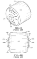
- Prior art voided bushing 101 of the type heretofore utilized in beam-type trailing arm axle suspension systems 20 and other suspension applications for trucks and tractor-trailers and the like, is best shown in FIGS. 9 and 10.
- Prior art bushing 101 includes an elastic, generally cylindrical-shaped body 103 formed with a central opening 104 which passes completely through the body about its longitudinal axis.
- a rigid metal sleeve 105 is friction fitted in opening 104 of body 103 and is bonded to the body at the peripheral surface of the sleeve by any suitable adhesive.
- Sleeve 105 extends slightly outwardly from both ends of opening 104 to provide means for pivotally attaching bushing 101 to suspension hanger 22 by passing a bolt 39 through metal sleeve 105 and a pair of wear pads 106 formed of any suitable plastic, each one of the pair being loosely disposed over a respective one of the ends of the metal sleeve (FIG. 3). Wear pads 106 protect the ends of beam mounting tube 100, each one of the ends of which abuts a respective one of the sidewalls of hanger 22.
- Elastic body 103 when used in tractor-trailer suspensions having a GAWR of from about 8200 kg to about 11000 kg (about 18,000 lbs.
- a pair of spaced-apart voids 107 is formed in each side of elastic body 103 of bushing 101. More specifically, a generally radially inwardly curving, rectangular-shaped void 107 is formed in each of the top and bottom portions of each side of body 103. Voids 107 enable prior art bushing 101 to achieve multifunctional characteristics. More specifically, the multifunctional characteristics include required load and deflection ratios, or static rates, of varying levels in different directions for semi-trailer axle suspension system applications.
- the bushing static rate is stiff in the horizontal radial direction, so that axle suspension system 20 remains substantially perpendicular to the direction of movement of the tractor-trailer despite horizontal loading which may be placed on the suspension system, and relatively soft in the vertical radial direction, to enable the suspension system and bushing 101 to absorb vertical loading shocks and provide a smooth ride for the vehicle occupants and any cargo carried by the vehicle.
- beam 24 generally is rectangular-shaped and includes spaced-apart top and bottom walls 25 and 26, respectively, and spaced-apart parallel inboard and outboard sidewalls 27 and 28, respectively.
- Top wall 25 is formed integrally with sidewalls 27, 28, and bottom wall 26 extends between, is welded to, and interconnects the sidewalls.
- An air spring 29 is suitably mounted on and extends between the upper surface of the rear end of top wall 25 and frame rail 38.
- a shock absorber 30 extends between and is mounted on inboard sidewall 27 of suspension beam 24 and hanger 22.
- An air brake chamber 31 of the semi-trailer braking system (only portions shown) is mounted on bottom wall 26 of suspension beam 24 by any suitable means such as welding.
- a piston 32 of brake chamber 31 in turn is pivotally attached to a slack adjuster 33, which in turn is immovably mounted on a cam shaft 34 of the braking system to provide for transfer of in-line loads from the brake chamber piston into a torsional load on the cam shaft.
- An axle 35 extends between and is immovably captured in suspension beam 24 and its corresponding opposite suspension beam of axle suspension system 20.
- brake chamber 31 On bottom wall 26 of beam 24 necessitates disposition of slack adjuster 33 between sidewalls 27, 28 of the beam.
- inboard sidewall 27 is provided with a cutout 36 to enable the slack adjuster to be accessed and/or removed from cam shaft 34.
- cutout 36 causes a potential weak spot in the structure of beam 24, which could weaken the suspension assembly 21 and/or suspension system 20 in certain situations such as when the beam is subjected to increased load capacity.
- beam 24 can be reinforced to counteract the potential weak spot, reinforcement would add unwanted weight and cost to suspension system 20.
- air-ride beam-type axle suspension systems 20 as described hereinabove in general utilize a large bushing 101 (FIGS. 9 and 10) which corresponds to the size/width of beam 24 and reacts to static loads, roll moments and braking forces encountered by the suspension system during normal operation.
- a wide hanger 22 is required to accommodate bushing 23 and typically is wider than the typical width of original equipment trailer frame rails 38, as best shown in FIG. 3.
- This size discrepancy requires shims and other accessory structures (not shown) to properly anchor hanger 22 to its respective frame rail 38. This is a penalty when compared to narrow leaf spring suspension system designs which generally fit within the typical trailer frame rail confines.
- leaf spring axle suspension systems generally are lighter in weight than air-ride beam-type axle suspension systems such as described at 20 above and shown in FIGS. 1-4.
- axle suspension system 20 must overcome less efficient axle support centers than a typical leaf spring axle suspension system, because large air spring 29 must be offset inboard to avoid hitting a tire (not shown) of trailer wheel 37, as best shown in FIG. 3. Trailing arm beam 24 must in turn be disposed further inboard to support air spring 29, thus moving the seat centers of axle 35 inboard with a resultant loss in axle support efficiency.
- axle suspension system 60 includes generally identical suspension assemblies 61 each suspended from a respective one of a pair of hangers 62, only one of the suspension assemblies will be described in detail herein and shown in FIGS. 5-8. All components of system 60 are formed of a suitable strong -metal or other sturdy material, unless otherwise noted.
- Hanger 62 is, by any suitable means, securely mounted on and depends from a respective one of the pair of spaced-apart, parallel longitudinally extending elongated frame rails 38 which are secured to and depend from the underside of the trailer of a tractor-trailer.
- the width of hanger 62 is less than the width of prior art suspension assembly hangers such as those identified at 22 in FIGS. 1-4.
- the reason for this decreased width W of hanger 62 will be described in detail hereinbelow.
- the decreased width of hanger 62 results in two practical advantages which require immediate description. First, reduced width hanger 62 closely matches the width of trailer frame rails 38, thus enabling hanger 62 to be directly mounted on its respective frame rail 38 without requiring shims or other special accessory parts as is required for many prior art hangers which are wider than the frame rail.
- a pivot bushing assembly 63 for pivotal mounting in hanger 62 and rigid attachment to the front end of a trailing arm or beam 64 by any suitable means such as welding, can be of reduced size/width, which assists in reducing the overall weight of suspension assembly 61.
- Bushing assembly 63 (FIG. 7) includes a beam mounting tube 110 which is welded to the front end of beam 64.
- a reduced-size voided pivot bushing 111, 111' is press-fitted into tube 110.
- the basic structure of a first embodiment reduced-size bushing 111 of the present invention, as well as a second embodiment reduced-size bushing 111' of the present invention, is described briefly immediately below, with a more detailed description of the structure and the key features of the first and second embodiment bushings appearing thereafter hereinbelow.
- Each one of a pair of alignment collars 112 is rigidly mounted in a respective slot (not shown) formed in each sidewall of hanger 62 to properly align tube 110 relative to the hanger.
- each reduced-size pivot bushing 111, 111' includes, respectively, an elastic, generally cylindrical-shaped body 113, 113' formed with a central opening 114, 114' which passes completely through the body about its horizontal pivotal axis.
- a rigid metal sleeve 115, 115' is friction fitted in opening 114, 114' of body 113, 113' and is bonded to the body at the peripheral surface of the sleeve by any suitable adhesive.
- Sleeve 115, 115' extends slightly outwardly from both ends of opening 114, 114' to provide means for pivotally attaching bushing 111, 111' to suspension hanger 62 by passing a bolt 79 through metal sleeve 115, 115' and a pair of wear pads 116 formed of any suitable plastic, each one of the pair being loosely disposed over a respective one of the ends of the metal sleeve (FIG. 7). Wear pads 116 protect the ends of beam mounting tube 110, each one of the ends of which abuts a respective one of the sidewalls of hanger 62.
- Metal sleeve 115, 115' can be made of any suitable hard metal such as steel.
- a pair of spaced-apart voids 117, 117' is formed in each side of elastic body 113, 113' of bushing 111, 111'. More specifically, a generally horizontal, rectangular-shaped void 117 is formed in each of said top and bottom portions of each side of body 113.
- beam 64 generally is rectangular shaped and includes spaced-apart top and bottom walls 65 and 66, respectively, and spaced-apart inboard and outboard sidewalls 67 and 68, respectively.
- Top wall 65 is formed integrally with sidewalls 67, 68, and bottom wall 66 extends between, is welded to, and interconnects the sidewalls.
- the sidewall 67 is angled rearwardly inboard relative to its respective frame rail 38 (FIG. 7).
- This rearward inboard disposition of inboard sidewall 67 when combined with the non-angular front-rear disposition of outboard sidewall 68 making it generally parallel to its respective frame rail 38, results in beam 64 having a taper from being narrower at hanger 62, to wider as it fans out rearwardly therefrom.
- beam 64 possesses less mass in the lower stressed portion of the beam adjacent to hanger 62 and bushing assembly 63, enabling use of a reduced size/width hanger and bushing 111, 111'.
- the tapered design enables beam 64 to possess greater mass in its high stress portions toward the rear of the beam, thus optimizing its weight.
- Air spring 69 is one factor which places stress on the rear portion of trailing arm beam 64.
- Air spring 69 formed of any suitable elastomer, is securely mounted on and extends between the upper surface of the rear end of top wall 65 and frame rail 38.
- the width of the front end of beam 64 is less than prior art beams, it can be appreciated that the inboard taper of sidewall 67 enables beam 64 to adequately support air spring 69 (FIG. 7) which is by necessity disposed slightly inboard to avoid interfering with a tire (not shown) of trailer wheel 77.
- axle 75 which extends between and is immovably captured in suspension beam 64 and its corresponding opposite suspension beam of axle suspension system 60, to be wider or more outboard than prior art axle seat centers, thus improving the efficiency of the support of axle 75.
- a shock absorber 70 extends between and is mounted on inboard sidewall 67 of suspension beam 64 and hanger 62.
- An air brake chamber 71 of the semi-trailer braking system (only portions shown) is mounted on bottom wall 66 of suspension beam 64 by any suitable means such as welding.
- a piston 72 of brake chamber 71 in turn is pivotally attached to a slack adjuster 73, which in turn is immovably mounted on a cam shaft 74 of the braking system to provide for transfer of in-line loads from the brake chamber piston into a torsional load on the cam shaft.
- axle suspension system 60 of the present invention provides access to/removal/replacement of slack adjuster 73 due to the rearward taper of inboard sidewall 67 providing adequate clearance for access to and especially removal/replacement of the slack adjuster from its location within beam 64, as best shown in FIGS. 5 and 7.
- the reduced-size voided pivot bushing embodiments 111, 111' useful in suspension assembly 61 display desirable multifunctional characteristics heretofore observed only in conventional-size voided pivot bushings of the type shown in FIGS. 9 and 10 and described hereinabove.
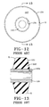
- prior art reduced-size solid bushings 121 of the type shown in FIGS. 11 to 13, while offering smaller size and weight characteristics have been unsuccessful in achieving the desirable multifunctional characteristics of their conventional-size voided counterparts.
- Prior art reduced-size solid bushing 121 includes an elastic, generally cylindrical-shaped body 123 formed with a central opening 124 which passes completely through the body about its horizontal pivotal axis.
- a rigid metal sleeve 125 is friction fitted in opening 124 of body 123, and is bonded to the body at the peripheral surface of the sleeve by any suitable adhesive.
- Sleeve 125 extends slightly outwardly from both ends of opening 124 to provide means for pivotally attaching bushing 121 to a hanger of a suspension assembly as has been described above for reduced-size voided pivot bushings 111, 111' of the present invention.
- Elastic body 123 when used in tractor-trailer suspensions having a GAWR of from about 8200 kg to about 11000 kg (about 18,000 lbs. to about 25,000 lbs), is formed of natural rubber having a durometer of from about 50 to about 75.
- Metal sleeve 125 is made of any hard metal such as steel.
- bushing 121 Although reduced-size solid pivot bushing 121 provides the required vertical load-deflection found in bushings exhibiting multifunctional characteristics, bushing 121 fails to provide adequate horizontal load-deflection. Specifically, horizontal load-deflection controls the lateral or side-to-side motion of suspension system 60. Solid bushing 121 allows unacceptable excessive lateral motion due to its lower load-deflection characteristics in the horizontal direction. Moreover, and as best shown in FIG. 14, when subjected to loading conditions of the type encountered in service in air-ride, beam-type trailing arm axle suspension system 60, bushing 121 exhibited reduced durability as evidenced by crack initiation C of bushing body 123 from friction fitted adhesively bonded bushing metal sleeve 125.
- press fitting of solid bushing 121 in mounting tube 120 causes the normally linear tapering sides of bushing 121 (FIG. 13) to bulge outwardly, thus further reducing the contact surface area between the bushing and the mounting tube.
- the contact surface area is reduced because the width of bushing body 123 must be significantly less than the width of mounting tube 120, otherwise the bulging sides of bushing 121 would extend outwardly from the ends of the mounting tube, thus making it impossible to mount bushing assembly 63 within hanger 62.
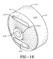
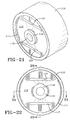
- First pivot bushing 111 is shown in FIGS. 16 to 24.
- the widths W and W 2 of elastic bushing body 113 like the width of reduced-size solid bushing body 123, each is about fifty percent of the width of conventional-size voided bushing 101, but its diameter D is larger than bushings 101 and 121 by about 6 mm (one-quarter of an inch).
- W is about 60 mm (2.35 inches) and W 2 is about 72 mm (2.82 inches) and D is about 159 mm (6.25 inches).
- reduced-size voided bushing 111 has two distinct surface profiles on each of its sides.
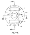
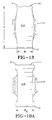
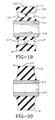
- a first surface profile exists generally about an imaginary horizontal line parallel to section line 20-20 shown in FIG. 17, and can be described as generally concave (FIGS. 18A and 20).
- a second surface profile exists generally about an imaginary vertical line parallel to section line 19-19 shown in FIG. 17, and can be described as generally concave from the radially inner most edge of each void 117 and on inward to metal sleeve 115. From the radially outermost edge of each void 117 and on outward to the periphery or end of elastic body 113, the second surface profile can be described as generally sidewardly protruding as best shown in FIGS. 16 to 19.
- reduced-size solid bushing 121 has a radiused or rounded edge R between each of its sides and its peripheral end, as best shown in FIGS. 11 and 13.
- the corresponding edge S' of reduced-size voided bushing 111 is generally free of a pronounced radius or rounding and is sharper in shape.
- the durometer range of reduced-size solid bushing 121 is from about 50 to about 75.
- elastic body 113 when used in tractor-trailer suspensions having a GAWR from about 8200 kg to about 11000 kg (about 18,000 lbs. to about 25,000 lbs), preferably is formed of natural rubber having a durometer of from about 75 to about 90, more preferably from about 75 to about 84, and most preferably from about 75 to about 79, with the rubber being available from the Goodyear Tire & Rubber Company of Akron, Ohio.
- each void 117 is a generally horizontal rectangular slot having radiused or rounded edges and generally rounded ends.
- each void preferably is from about 1400 mm 2 (2:17 square inches) to about 1860 mm 2 (2.89 square inches), more preferably from about 1430 mm 2 (2.23 to about 1790 mm 2 2.77 square inches), and most preferably from about 1470 mm 2 (2.29 to about 1710 mm 2 2.65 square inches).
- the total area of each void preferably is from about 1400 mm 2 (2:17 square inches) to about 1860 mm 2 (2.89 square inches), more preferably from about 1430 mm 2 (2.23 to about 1790 mm 2 2.77 square inches), and most preferably from about 1470 mm 2 (2.29 to about 1710 mm 2 2.65 square inches).
- each void 117 which extends outwardly beyond a pair of spaced, imaginary vertical lines T f and T r , respectively, which are tangential to the front and rear outer surfaces of metal sleeve 115, preferably is from about 27 percent to about 46 percent of the total area of each void 117, more preferably from about 29 percent to about 43 percent, and most preferably from about 31 percent to about 40 percent of the total area of each of the voids.
- first embodiment reduced-size voided bushing 111 of the present invention overcomes all of the problems associated with prior art reduced-size solid bushing 121. Specifically, the combination of the variable concave/protruding side profile and unradiused side to peripheral edge profile of bushing 111, together with elongated straight horizontal voids 117 having generally rounded ends and choice of rubber durometer, enables bushing 111 to achieve the multifunctional characteristics heretofore demonstrated only in conventional-size voided bushing 101. Specifically, the multifunctional characteristics of bushing 111 include required load and deflection ratios, or static rates, of varying levels in different directions for semi-trailer axle suspension system applications.
- the bushing static rate is stiff in the horizontal radial direction, so that axle suspension system 60 remains substantially perpendicular to the direction of movement of the vehicle despite horizontal loading which may be placed on the suspension system, and relatively soft in the vertical radial direction, to enable the suspension system and bushing 111 to absorb vertical loading shocks and provide proper roll-stability for the trailer.
- shape and positioning of voids 117 is important for other reasons as well.
- the slightly rounded ends of each void 117 assist in preventing premature crack sites in bushing body 113 adjacent to the ends of voids 117 by reducing localized buckling or puckering.
- the above-described combination of features of bushing 111 prevents the type of cracking observed in reduced-size solid bushing 121 as shown in FIG. 14, namely, cracking separation of bushing body 123 from metal sleeve 125.
- the protruding portions of the sides of bushing 111 combined with the larger outside diameter of the bushing prevent the migration and twisting problem described hereinabove for prior art solid bushing 121.
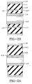
- the larger diameter of bushing body 113 enables greater compression force when bushing 111 is press fitted into beam mounting tube 110, as best shown in FIGS. 21 to 24. This compression force of bushing body 113 against beam mounting tube 110 is about 19 percent compared to about 13 percent for solid bushing 121, which translates to increased interference pressure to hold bushing 111 in place in tube 110.
- variable concave/protruding side profile and unradiused side to periphery edge profile of bushing 111 also increases the contact surface area and resulting compression between the peripheral surface of bushing body 113 and the inner surface of mounting tube 110.
- mounting tube 110 is substantially filled by bushing 111. This filling of mounting tube 110 assists bushing 111 in achieving its multifunctional characteristics, and also helps prevent bushing migration or twisting.
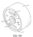
- Second pivot bushing 111' is shown in FIGS. 25 to 32.
- the width W' of elastic bushing body 113' like the width of reduced-size solid bushing body 123, is about 50 percent of the width of conventional size voided bushing 101, but its diameter D' is larger than bushings 101 and 121 by about 6 mm (one-quarter of an inch).
- W' is about 60 mm (2.37 inches) and D' is about 159 mm (6.25 inches).
- reduced-size voided bushing 111' has a surface profile that can best be described as generally concave, as best shown in FIGS. 25 and 27, 28.
- reduced-size solid bushing 121 has a radiused or rounded edge R between each of its sides and its peripheral end, as best shown in FIGS. 11 and 13.
- the corresponding edge S' of reduced-size voided bushing 111' is generally free of a pronounced radius or rounding and is sharper in shape.
- the durometer range of reduced-size solid bushing 121 is from about 50 to about 75.
- elastic body 113' when used in tractor-trailer suspensions having a GAWR from about 8200 kg to about 11000 kg (about 18,000 lbs. to about 25,000 lbs), preferably is formed of natural rubber having a durometer of from about 75 to about 90, more preferably from about 78 to 88, and most preferably from about 82 to about 86, with the rubber being available from the Goodyear Tire & Rubber Company of Akron, OH.
- each void 117' is a generally horizontal rectangular slot having generally rounded ends.
- each void preferably is from about 1240 mm 2 (1.93 square inches) to about 1670 mm 2 (2.59 square inches), more preferably from about 1280 mm 2 (1.99 to about 1600 mm 2 2.48 square inches), and most preferably from about 1310 mm 2 (2.04 to about 1530 mm 2 2.37 square inches).
- the total area of each void preferably is from about 1240 mm 2 (1.93 square inches) to about 1670 mm 2 (2.59 square inches), more preferably from about 1280 mm 2 (1.99 to about 1600 mm 2 2.48 square inches), and most preferably from about 1310 mm 2 (2.04 to about 1530 mm 2 2.37 square inches).
- each void 117' which extends outwardly beyond a pair of spaced, imaginary vertical lines T' f and T' r , respectively, which are tangential to the front and rear outer surfaces of metal sleeve 115', preferably is from about 21 percent to about 35 percent of the total area of each void 117', more preferably from about 23 percent to about 31 percent, and most preferably from about 25 percent to about 27 percent of the total area of each of the voids.
- second embodiment of reduced-size voided bushing 111' of the present invention overcomes the problems associated with prior art reduced-size solid bushing 121 in the same way as first embodiment 111', except for the absence of protruding side profile.
- improved bushings 111, 111' can be employed in suspension assembly 61, and the improved bushings have been designed to be durable as well as to withstand static loads, roll moments and braking forces encountered during normal operation of the semi-trailer.
Landscapes
- Engineering & Computer Science (AREA)
- Mechanical Engineering (AREA)
- General Engineering & Computer Science (AREA)
- Vehicle Body Suspensions (AREA)
- Springs (AREA)
- Valve Device For Special Equipments (AREA)
- Shafts, Cranks, Connecting Bars, And Related Bearings (AREA)
- Rod-Shaped Construction Members (AREA)
- Supports For Pipes And Cables (AREA)
- Transition And Organic Metals Composition Catalysts For Addition Polymerization (AREA)
Abstract
Description
Claims (21)
- A bushing (111) including:characterised in that(a) an elastic, generally cylindrical-shaped body (113) having a pair of spaced-apart generally concave sides and being formed with a central opening (114) which passes completely through said body (113) and each of said sides about a horizontal pivotal axis of the body (113), said body (113) having an edge formed at an interface of each of said sides with a peripheral end of said body;(b) a mounting tube (110) in which said elastic body (113) is fitted;(c) a rigid sleeve (115) immovably mounted in said central opening (114), of the elastic body (113), said rigid sleeve (115) outside diameter being generally equal to the central opening (114) diameter, the sleeve (115) extending substantially the entire width of said central opening (114) to facilitate mounting of said bushing;(d) a pair of spaced apart voids (117) formed in each of said elastic body (113) sides, said pair of voids (117) being formed in each of the sides above and below the central opening (114), and an imaginary vertical center of each of said voids (117) being disposed about 90 degrees from an imaginary horizontal plane passing transversely through the body (113) when said bushing (111) is mounted on a vehicle suspension, said voids each being generally horizontal rectangular-shaped, said elastic body (113) being generally solid apart from said voids (117) and said central opening (114), so that said bushing (111) is more rigid in the direction of said horizontal plane than in the direction of said vertical center;
said bushing (111) is for use in vehicle suspension; said elastic body (113) is mountable within said mounting tube (110) with flattening of the concave sides thereof to substantially fill said tube (110), and said edge thereof is generally unradiused. - The bushing of claim 1 in which said elastic body has a width of 58-71mm (2.3 - 2.8 inches) and a diameter of about 159 mm (6.25 inches).
- The bushing (111) of claim 1, in which said bushing body (113) is formed of natural rubber having a durometer of from about 75 to about 90.
- The bushing (111) of claim 1, in which said bushing body (113) is formed of natural rubber having a durometer of from about 78 to about 88.
- The bushing (111) of claim 1, in which said bushing body (113) is formed of natural rubber having a durometer of from about 82 to about 86.
- The bushing (111) of claim 2, in which the area of each of said voids (117) is from about 1240 mm2 (1.93 square inches) to about 1670 mm2 (2.59 square inches).
- The bushing (111) of claim 2, in which the area of each of said voids (117) is from about 1280 mm2 (1.99 square inches) to about 1600 mm2 (2.48 square inches).
- The bushing (111) of claim 2, in which the area of each of said voids (117) is from about 1310 mm2 (2.04 square inches) to about 1530 mm2 (2.37 square inches).
- The bushing (111) of claim 1, in which from about 21 percent to about 35 percent of the total area of each of said voids (117) extends beyond an area bounded by a pair of spaced imaginary vertical lines located tangential to an outer surface of said sleeve (115).
- The bushing (111) of claim 1, in which from about 23 percent to about 31 percent of the total area of each of said voids (117) extends beyond an area bounded by a pair of spaced imaginary vertical lines located tangential to an outer surface of said sleeve (115)
- The bushing (111) of claim 1, in which from about 25 percent to about 27 percent of the total area of each of said voids (117) extends beyond an area bounded by a pair of spaced imaginary vertical lines located tangential to an outer surface of said sleeve (115).
- A bushing (111) according to claim 1 or 2 in which said generally concave sides have a concave shape between a radially innermost edge of each of said voids (117) and said rigid sleeve (115) and a generally sidewardly protruding shape between a radially outermost edge of each of said voids (117) and said peripheral end of said elastic body.
- The bushing (111) of claim 12, in which said bushing body (113) is formed of natural rubber having a durometer of from about 75 to about 90.
- The bushing (111) of claim 12, in which said bushing body (113) is formed of natural rubber having a durometer of from about 75 to about 84.
- The bushing (111) of claim 12, in which said bushing body (113) is formed of natural rubber having a durometer of from about 75 to about 79.
- The bushing (111) of claim 12 as dependent on claim 2, in which the area of each of said voids (117) is from about 1400 mm2 (2.17 square inches) to about 1860 mm2 (2.89 square inches).
- The bushing (111) of claim 16, in which the area of each of said voids (117) is from about 1430 mm2 (2.23 square inches) to about 1790 mm2 (2.77 square inches).
- The bushing (111) of claim 17, in which the area of each of said voids (117) is from about 1470 mm2 (2.29 square inches) to about 1710 mm2 (2.65 square inches).
- The bushing (111) of claim 12, in which from about 27 percent to about 46 percent of the total area of each of said voids (117) extends beyond an area bounded by a pair of spaced imaginary vertical lines located tangential to an outer surface of said sleeve (115).
- The bushing (111) of claim 12, in which fromabout 29 percent to about 43 percent of the total area of each of said voids (117) extends beyond an area bounded by a pair of spaced imaginary vertical lines located tangential to an outer surface of said sleeve (115).
- The bushing (111) of claim 12, in which from about 31 percent to about 40 percent of the total area of each of said voids (117) extends beyond an area bounded by a pair of spaced imaginary vertical lines located tangential to an outer surface of said sleeve (115).
Applications Claiming Priority (5)
| Application Number | Priority Date | Filing Date | Title |
|---|---|---|---|
| US70409096A | 1996-08-28 | 1996-08-28 | |
| US704090 | 1996-08-28 | ||
| US841795 | 1997-05-05 | ||
| US08/841,795 US5996981A (en) | 1996-08-28 | 1997-05-05 | Reduced size bushing for beam-type axle suspension system |
| PCT/US1997/015096 WO1998009094A1 (en) | 1996-08-28 | 1997-08-27 | Beam-type axle suspension system |
Publications (2)
| Publication Number | Publication Date |
|---|---|
| EP0918955A1 EP0918955A1 (en) | 1999-06-02 |
| EP0918955B1 true EP0918955B1 (en) | 2000-11-08 |
Family
ID=27107259
Family Applications (1)
| Application Number | Title | Priority Date | Filing Date |
|---|---|---|---|
| EP97938650A Expired - Lifetime EP0918955B1 (en) | 1996-08-28 | 1997-08-27 | Bushings for axle suspension systems |
Country Status (19)
| Country | Link |
|---|---|
| US (1) | US5996981A (en) |
| EP (1) | EP0918955B1 (en) |
| KR (1) | KR100315528B1 (en) |
| AT (1) | ATE197497T1 (en) |
| AU (1) | AU707479B2 (en) |
| BR (1) | BR9711267A (en) |
| CA (1) | CA2263866C (en) |
| DE (1) | DE69703496T2 (en) |
| DK (1) | DK0918955T3 (en) |
| ES (1) | ES2153684T3 (en) |
| GR (1) | GR3035229T3 (en) |
| HU (1) | HU220655B1 (en) |
| NO (1) | NO316337B1 (en) |
| NZ (1) | NZ334263A (en) |
| PL (1) | PL185697B1 (en) |
| PT (1) | PT918955E (en) |
| TR (1) | TR199900441T2 (en) |
| WO (1) | WO1998009094A1 (en) |
| YU (1) | YU10199A (en) |
Families Citing this family (39)
| Publication number | Priority date | Publication date | Assignee | Title |
|---|---|---|---|---|
| MXPA01007859A (en) * | 1999-02-04 | 2002-04-10 | Holland Neway Int Inc | Trailing arm suspension with brake assembly mounting bracket. |
| DE10029639C2 (en) * | 2000-06-15 | 2002-04-18 | Daimler Chrysler Ag | Coupling an axle beam to a vehicle leaf spring or a trailing arm |
| NZ524252A (en) * | 2000-07-20 | 2004-03-26 | Lauras As | Cox-2 inhibitors for treating HIV and AIDS |
| GB0021716D0 (en) * | 2000-09-05 | 2000-10-18 | Meritor Heavy Vehicle Sys Ltd | Vehicle suspension axle wrap |
| GB0021718D0 (en) * | 2000-09-05 | 2000-10-18 | Meritor Heavy Vehicle Sys Ltd | Vehicle suspension beam |
| GB0021719D0 (en) * | 2000-09-05 | 2000-10-18 | Meritor Heavy Vehicle Sys Ltd | Pivot bearing |
| US6446993B1 (en) * | 2000-10-18 | 2002-09-10 | Daimlerchrysler Corporation | Control arm bushing |
| US20030025258A1 (en) * | 2001-08-02 | 2003-02-06 | Collyer Brent R. | Grooved or ribbed bushing and mating grooved or ribbed bushing receiving bore included within a suspension component |
| US7044457B2 (en) * | 2001-11-05 | 2006-05-16 | Lord Corporation | Mount with replaceable load bearing and rebound members |
| US20030201589A1 (en) * | 2002-04-30 | 2003-10-30 | Adema Daniel R. | Bushing with anti-walkout feature |
| US6827360B2 (en) * | 2002-10-24 | 2004-12-07 | Arvinmeritor Technology, Llc | One-piece trailing arm section |
| US20040084822A1 (en) | 2002-11-05 | 2004-05-06 | Collyer Brent R. | Bushing with performance tuning features |
| GB2396140C (en) * | 2002-12-13 | 2011-06-23 | Meritor Heavy Vehicle Sys Ltd | A suspension trailing arm and method of making a suspension trailing arm |
| US20040113337A1 (en) * | 2002-12-17 | 2004-06-17 | Landry Joseph Raymond | Elastomeric bushing |
| DE602004026312D1 (en) * | 2003-07-18 | 2010-05-12 | Barnes Group Inc | DAMPER AND DAMPING CYLINDER FOR PLASTER OR BASE PLATE OF A PRESS |
| US7090309B2 (en) * | 2003-11-25 | 2006-08-15 | Dana Corporation | Variable wall thickness trailer axles |
| US20050156398A1 (en) * | 2004-01-16 | 2005-07-21 | John Edward Ramsey | Device for leveling a trailer floor |
| US7445220B2 (en) | 2004-02-06 | 2008-11-04 | Daimler Trucks North America Llc | Vehicle axle apparatus |
| DE102005043234B4 (en) * | 2005-09-09 | 2017-05-11 | Boge Elastmetall Gmbh | Method of making an elastomeric bushing bearing |
| DE102006021011B4 (en) | 2006-05-04 | 2021-05-12 | Boge Elastmetall Gmbh | Bush bearing with bearing body profiled on the axial side |
| US7954793B2 (en) * | 2006-12-08 | 2011-06-07 | Enidine, Inc. | Elastomeric isolator |
| WO2008142876A1 (en) * | 2007-05-17 | 2008-11-27 | Mitsubishi Electric Corporation | Bushing for fixing device and device fixing unit using the same |
| US20090072458A1 (en) * | 2007-09-17 | 2009-03-19 | The Pullman Company | Self-constrained dynamic damper |
| US8348249B2 (en) * | 2008-10-07 | 2013-01-08 | Dadco, Inc. | Reaction device for forming equipment |
| US8128076B2 (en) * | 2008-11-07 | 2012-03-06 | Itt Manfacturing Enterprises, Inc. | Noise attenuator for side wall panel |
| US9016970B2 (en) * | 2011-06-08 | 2015-04-28 | United States Postal Service | Elastomeric force mitigating joint |
| US10767721B2 (en) | 2015-08-18 | 2020-09-08 | Hendrickson Usa, L.L.C. | Bar pin bushing for vehicle suspension |
| US10704637B2 (en) | 2015-08-18 | 2020-07-07 | Hendrickson Usa, L.L.C. | Bar pin bushing for vehicle suspension |
| US9809073B2 (en) | 2015-09-29 | 2017-11-07 | Hendrickson Usa, L.L.C. | Tapered axle/suspension system beam for heavy-duty vehicles |
| US10017026B2 (en) * | 2015-11-10 | 2018-07-10 | Federal-Mogul Motorparts Llc | Sway bar linkage with bushing |
| GB201521841D0 (en) | 2015-12-11 | 2016-01-27 | Hendrickson United Kingdom Ltd | Axle/suspension systems |
| BR112018068162B1 (en) | 2016-03-09 | 2022-11-29 | Hendrickson Usa, L.L.C. | AIR DISC BRAKE SYSTEM FOR A HEAVY VEHICLE AND AIR DISC BRAKE ACTUATOR ASSEMBLY FOR A HEAVY VEHICLE |
| US10807428B1 (en) | 2017-01-06 | 2020-10-20 | Jason M. Klein | Leaf-spring suspension systems with compliant oversized pivot bushings |
| KR102310502B1 (en) * | 2017-05-10 | 2021-10-08 | 현대자동차주식회사 | Double Compression Ratio type Bush and Suspension System thereby |
| KR101951211B1 (en) * | 2017-05-15 | 2019-02-26 | 주식회사 두성특장차 | Independent stub axle structure |
| WO2019036354A1 (en) | 2017-08-14 | 2019-02-21 | Hendrickson Usa, L.L.C. | Suspension assembly with disc brake actuator protection |
| CA3066229C (en) * | 2017-08-16 | 2021-11-23 | Hendrickson Usa, L.L.C. | Multi-functional suspension bushing |
| BR202017023671Y1 (en) * | 2017-11-01 | 2022-10-11 | Castertech Fundição E Tecnologia Ltda | CONSTRUCTION ARRANGEMENT INSERTED IN BUSHING FOR PNEUMATIC SUSPENSION ARM |
| DE102019209917A1 (en) * | 2019-07-05 | 2021-01-07 | Ford Global Technologies, Llc | Axle suspension for a vehicle |
Family Cites Families (26)
| Publication number | Priority date | Publication date | Assignee | Title |
|---|---|---|---|---|
| US2375105A (en) * | 1942-12-24 | 1945-05-01 | Us Rubber Co | Resilient mounting |
| FR1251719A (en) * | 1959-03-25 | 1961-01-20 | Gomma Antivibranti Applic | Anti-vibration elastic support for machine parts, particularly for transmission shafts |
| US3191896A (en) * | 1962-03-05 | 1965-06-29 | Hamilton Kent Mfg Company | Vibration pad |
| US3140081A (en) * | 1963-03-18 | 1964-07-07 | Lord Mfg Co | Tube form mounting |
| US3650520A (en) * | 1970-06-29 | 1972-03-21 | Rogers Corp | Energy absorbing device |
| US3762747A (en) * | 1972-09-25 | 1973-10-02 | Gen Motors Corp | Grommet |
| DE7718677U1 (en) * | 1977-06-14 | 1982-12-02 | Lemförder Metallwaren AG, 2844 Lemförde | Spring element, in particular for the elastic mounting of drive units or other assemblies in motor vehicles |
| US4166640B1 (en) * | 1978-04-14 | 1994-03-22 | Boler Company Inc | Axle suspension for wheeled vehicles |
| FR2473662B1 (en) * | 1980-01-09 | 1987-02-27 | Siette | ELASTIC SUPPORT FOR SUSPENDING AN OSCILLATING BODY ON A CARRIER STRUCTURE, IN PARTICULAR A MOTOR ON THE CHASSIS OF A MOTOR VEHICLE |
| JPS5751036A (en) * | 1980-09-11 | 1982-03-25 | Toyota Motor Corp | Cylindrical bush assembly |
| US4504080A (en) * | 1983-05-16 | 1985-03-12 | Turner Quick-Lift Corporation | Leaf spring lift axle suspension system |
| FR2599450B1 (en) * | 1986-06-03 | 1990-08-10 | Hutchinson | IMPROVEMENTS ON HYDRAULIC ANTI-VIBRATION SUPPORT SLEEVES |
| US4732407A (en) * | 1986-06-10 | 1988-03-22 | Fuji Jukogyo Kabushiki Kaisha | Suspension system for a motor vehicle |
| JPH0774658B2 (en) * | 1987-03-31 | 1995-08-09 | 鬼怒川ゴム工業株式会社 | Anti-vibration bush |
| JP2634062B2 (en) * | 1988-06-20 | 1997-07-23 | 鬼怒川ゴム工業株式会社 | Anti-vibration bush |
| US5170997A (en) * | 1989-11-30 | 1992-12-15 | Hutchinson | Resilient articulation with variable stiffness |
| US4991868A (en) * | 1989-12-19 | 1991-02-12 | The Boler Company | Vehicle suspension beam pivot connection |
| JPH0425628A (en) * | 1990-05-15 | 1992-01-29 | Bridgestone Corp | Bush type oscillation proof rubber |
| JPH0442937U (en) * | 1990-08-09 | 1992-04-13 | ||
| US5127668A (en) * | 1991-01-24 | 1992-07-07 | Raidel John E | Torque beam with clamped mono-pivot bushing and flexible axle seat |
| JPH04272527A (en) * | 1991-02-26 | 1992-09-29 | Toyota Motor Corp | Bush |
| JP2618767B2 (en) * | 1991-05-17 | 1997-06-11 | 東海ゴム工業株式会社 | Steering coupling |
| AU666572B2 (en) * | 1992-10-19 | 1996-02-15 | Hendrickson International Corporation | Axle suspension systems |
| DE9414971U1 (en) * | 1993-10-02 | 1994-11-17 | Saar-Gummiwerk GmbH, 66687 Wadern | Elastic suspension for fastening dynamically stressed functional parts |
| DE4414276C1 (en) * | 1994-04-23 | 1995-08-10 | Stewing Kunststoff | Door opening limit |
| DE4438932C2 (en) * | 1994-10-31 | 1998-07-02 | Daimler Benz Ag | Hydro bearing |
-
1997
- 1997-05-05 US US08/841,795 patent/US5996981A/en not_active Expired - Lifetime
- 1997-08-27 HU HU0002988A patent/HU220655B1/en unknown
- 1997-08-27 WO PCT/US1997/015096 patent/WO1998009094A1/en not_active Ceased
- 1997-08-27 ES ES97938650T patent/ES2153684T3/en not_active Expired - Lifetime
- 1997-08-27 BR BR9711267-4A patent/BR9711267A/en not_active IP Right Cessation
- 1997-08-27 NZ NZ334263A patent/NZ334263A/en not_active IP Right Cessation
- 1997-08-27 AU AU40932/97A patent/AU707479B2/en not_active Expired
- 1997-08-27 TR TR1999/00441T patent/TR199900441T2/en unknown
- 1997-08-27 PT PT97938650T patent/PT918955E/en unknown
- 1997-08-27 AT AT97938650T patent/ATE197497T1/en active
- 1997-08-27 EP EP97938650A patent/EP0918955B1/en not_active Expired - Lifetime
- 1997-08-27 DE DE69703496T patent/DE69703496T2/en not_active Expired - Lifetime
- 1997-08-27 PL PL97331850A patent/PL185697B1/en unknown
- 1997-08-27 CA CA002263866A patent/CA2263866C/en not_active Expired - Lifetime
- 1997-08-27 DK DK97938650T patent/DK0918955T3/en active
-
1999
- 1999-02-25 NO NO19990895A patent/NO316337B1/en not_active IP Right Cessation
- 1999-02-26 YU YU10199A patent/YU10199A/en unknown
- 1999-02-27 KR KR1019997001637A patent/KR100315528B1/en not_active Expired - Lifetime
-
2001
- 2001-01-11 GR GR20010400045T patent/GR3035229T3/en unknown
Also Published As
| Publication number | Publication date |
|---|---|
| NO316337B1 (en) | 2004-01-12 |
| KR100315528B1 (en) | 2001-11-29 |
| US5996981A (en) | 1999-12-07 |
| KR20000035910A (en) | 2000-06-26 |
| DE69703496T2 (en) | 2001-05-03 |
| PL331850A1 (en) | 1999-08-16 |
| DE69703496D1 (en) | 2000-12-14 |
| DK0918955T3 (en) | 2001-02-05 |
| NZ334263A (en) | 1999-04-29 |
| ATE197497T1 (en) | 2000-11-11 |
| AU707479B2 (en) | 1999-07-08 |
| CA2263866C (en) | 2001-04-17 |
| TR199900441T2 (en) | 1999-08-23 |
| WO1998009094A1 (en) | 1998-03-05 |
| BR9711267A (en) | 2000-01-18 |
| NO990895L (en) | 1999-04-28 |
| YU10199A (en) | 2001-09-28 |
| EP0918955A1 (en) | 1999-06-02 |
| AU4093297A (en) | 1998-03-19 |
| PL185697B1 (en) | 2003-07-31 |
| GR3035229T3 (en) | 2001-04-30 |
| PT918955E (en) | 2001-04-30 |
| NO990895D0 (en) | 1999-02-25 |
| HU220655B1 (en) | 2002-03-28 |
| ES2153684T3 (en) | 2001-03-01 |
| HUP0002988A2 (en) | 2000-12-28 |
| HUP0002988A3 (en) | 2001-02-28 |
| CA2263866A1 (en) | 1998-03-05 |
Similar Documents
| Publication | Publication Date | Title |
|---|---|---|
| US5996981A (en) | Reduced size bushing for beam-type axle suspension system | |
| EP2230106B1 (en) | Vehicle suspension | |
| US7722064B2 (en) | Tapered joint for vehicle suspension components | |
| EP0863060B1 (en) | Axle suspension systems | |
| US8177246B2 (en) | Axle seat for vehicle suspensions | |
| AU2002248483A1 (en) | Vehicle suspension | |
| AU2018318057B2 (en) | Beam for suspension assemblies of heavy-duty vehicle axle/suspension systems | |
| US11813918B2 (en) | Axle/suspension system for heavy-duty vehicles | |
| AU2009200960B2 (en) | Tapered joint for vehicle suspension components | |
| MXPA99001945A (en) | Beam-type axle suspension system | |
| AU2008200853B2 (en) | Axle clamp assembly top pad and air spring mounting assembly |
Legal Events
| Date | Code | Title | Description |
|---|---|---|---|
| PUAI | Public reference made under article 153(3) epc to a published international application that has entered the european phase |
Free format text: ORIGINAL CODE: 0009012 |
|
| 17P | Request for examination filed |
Effective date: 19990322 |
|
| AK | Designated contracting states |
Kind code of ref document: A1 Designated state(s): AT BE CH DE DK ES FI FR GB GR IE IT LI LU NL PT SE |
|
| GRAG | Despatch of communication of intention to grant |
Free format text: ORIGINAL CODE: EPIDOS AGRA |
|
| 17Q | First examination report despatched |
Effective date: 19990924 |
|
| GRAG | Despatch of communication of intention to grant |
Free format text: ORIGINAL CODE: EPIDOS AGRA |
|
| GRAG | Despatch of communication of intention to grant |
Free format text: ORIGINAL CODE: EPIDOS AGRA |
|
| GRAH | Despatch of communication of intention to grant a patent |
Free format text: ORIGINAL CODE: EPIDOS IGRA |
|
| RTI1 | Title (correction) |
Free format text: BUSHINGS FOR AXLE SUSPENSION SYSTEMS |
|
| GRAH | Despatch of communication of intention to grant a patent |
Free format text: ORIGINAL CODE: EPIDOS IGRA |
|
| GRAA | (expected) grant |
Free format text: ORIGINAL CODE: 0009210 |
|
| AK | Designated contracting states |
Kind code of ref document: B1 Designated state(s): AT BE CH DE DK ES FI FR GB GR IE IT LI LU NL PT SE |
|
| REF | Corresponds to: |
Ref document number: 197497 Country of ref document: AT Date of ref document: 20001111 Kind code of ref document: T |
|
| REG | Reference to a national code |
Ref country code: CH Ref legal event code: EP |
|
| REG | Reference to a national code |
Ref country code: IE Ref legal event code: FG4D |
|
| REF | Corresponds to: |
Ref document number: 69703496 Country of ref document: DE Date of ref document: 20001214 |
|
| ET | Fr: translation filed | ||
| ITF | It: translation for a ep patent filed | ||
| REG | Reference to a national code |
Ref country code: DK Ref legal event code: T3 |
|
| REG | Reference to a national code |
Ref country code: ES Ref legal event code: FG2A Ref document number: 2153684 Country of ref document: ES Kind code of ref document: T3 |
|
| REG | Reference to a national code |
Ref country code: PT Ref legal event code: SC4A Free format text: AVAILABILITY OF NATIONAL TRANSLATION Effective date: 20010206 |
|
| PLBE | No opposition filed within time limit |
Free format text: ORIGINAL CODE: 0009261 |
|
| STAA | Information on the status of an ep patent application or granted ep patent |
Free format text: STATUS: NO OPPOSITION FILED WITHIN TIME LIMIT |
|
| 26N | No opposition filed | ||
| REG | Reference to a national code |
Ref country code: GB Ref legal event code: IF02 |
|
| REG | Reference to a national code |
Ref country code: GB Ref legal event code: 732E |
|
| REG | Reference to a national code |
Ref country code: PT Ref legal event code: PC4A Owner name: HENDRICKSON INTERNATIONAL CORPORATION, US Effective date: 20050824 |
|
| REG | Reference to a national code |
Ref country code: FR Ref legal event code: TP |
|
| REG | Reference to a national code |
Ref country code: CH Ref legal event code: PUE Owner name: HENDRICKSON INTERNATIONAL CORPORATION Free format text: THE BOLER COMPANY.#500 PARK BOULEVARD, SUITE 1010#ITASCA, ILLINOIS 60143-1285 (US) -TRANSFER TO- HENDRICKSON INTERNATIONAL CORPORATION#500 PARK BOULEVARD SUITE 1010#ITASCA, IL 60143 (US) |
|
| NLS | Nl: assignments of ep-patents |
Owner name: HENDRICKSON INTERNATIONAL CORPORATION Effective date: 20060516 |
|
| REG | Reference to a national code |
Ref country code: ES Ref legal event code: PC2A |
|
| REG | Reference to a national code |
Ref country code: FR Ref legal event code: PLFP Year of fee payment: 20 |
|
| PGFP | Annual fee paid to national office [announced via postgrant information from national office to epo] |
Ref country code: LU Payment date: 20160831 Year of fee payment: 20 Ref country code: NL Payment date: 20160826 Year of fee payment: 20 |
|
| PGFP | Annual fee paid to national office [announced via postgrant information from national office to epo] |
Ref country code: DK Payment date: 20160831 Year of fee payment: 20 Ref country code: CH Payment date: 20160829 Year of fee payment: 20 Ref country code: IE Payment date: 20160826 Year of fee payment: 20 Ref country code: GB Payment date: 20160830 Year of fee payment: 20 Ref country code: DE Payment date: 20160826 Year of fee payment: 20 Ref country code: IT Payment date: 20160824 Year of fee payment: 20 Ref country code: FI Payment date: 20160831 Year of fee payment: 20 |
|
| PGFP | Annual fee paid to national office [announced via postgrant information from national office to epo] |
Ref country code: SE Payment date: 20160829 Year of fee payment: 20 Ref country code: AT Payment date: 20160803 Year of fee payment: 20 Ref country code: FR Payment date: 20160825 Year of fee payment: 20 Ref country code: GR Payment date: 20160829 Year of fee payment: 20 Ref country code: PT Payment date: 20160804 Year of fee payment: 20 |
|
| PGFP | Annual fee paid to national office [announced via postgrant information from national office to epo] |
Ref country code: BE Payment date: 20160829 Year of fee payment: 20 Ref country code: ES Payment date: 20160826 Year of fee payment: 20 |
|
| REG | Reference to a national code |
Ref country code: DE Ref legal event code: R071 Ref document number: 69703496 Country of ref document: DE |
|
| REG | Reference to a national code |
Ref country code: DK Ref legal event code: EUP Effective date: 20170827 |
|
| REG | Reference to a national code |
Ref country code: NL Ref legal event code: MK Effective date: 20170826 |
|
| REG | Reference to a national code |
Ref country code: CH Ref legal event code: PL |
|
| REG | Reference to a national code |
Ref country code: GB Ref legal event code: PE20 Expiry date: 20170826 |
|
| REG | Reference to a national code |
Ref country code: SE Ref legal event code: EUG |
|
| REG | Reference to a national code |
Ref country code: AT Ref legal event code: MK07 Ref document number: 197497 Country of ref document: AT Kind code of ref document: T Effective date: 20170827 |
|
| REG | Reference to a national code |
Ref country code: IE Ref legal event code: MK9A |
|
| PG25 | Lapsed in a contracting state [announced via postgrant information from national office to epo] |
Ref country code: IE Free format text: LAPSE BECAUSE OF EXPIRATION OF PROTECTION Effective date: 20170827 Ref country code: PT Free format text: LAPSE BECAUSE OF EXPIRATION OF PROTECTION Effective date: 20170905 Ref country code: GB Free format text: LAPSE BECAUSE OF EXPIRATION OF PROTECTION Effective date: 20170826 |
|
| REG | Reference to a national code |
Ref country code: BE Ref legal event code: MK Effective date: 20170827 |
|
| REG | Reference to a national code |
Ref country code: ES Ref legal event code: FD2A Effective date: 20171204 |
|
| PG25 | Lapsed in a contracting state [announced via postgrant information from national office to epo] |
Ref country code: ES Free format text: LAPSE BECAUSE OF EXPIRATION OF PROTECTION Effective date: 20170828 |