EP0918551B1 - Medical irrigation pump and system - Google Patents
Medical irrigation pump and system Download PDFInfo
- Publication number
- EP0918551B1 EP0918551B1 EP97936418A EP97936418A EP0918551B1 EP 0918551 B1 EP0918551 B1 EP 0918551B1 EP 97936418 A EP97936418 A EP 97936418A EP 97936418 A EP97936418 A EP 97936418A EP 0918551 B1 EP0918551 B1 EP 0918551B1
- Authority
- EP
- European Patent Office
- Prior art keywords
- pump
- controller
- housing
- motor
- pump body
- Prior art date
- Legal status (The legal status is an assumption and is not a legal conclusion. Google has not performed a legal analysis and makes no representation as to the accuracy of the status listed.)
- Expired - Lifetime
Links
- 230000002262 irrigation Effects 0.000 title claims description 53
- 238000003973 irrigation Methods 0.000 title claims description 53
- 238000000034 method Methods 0.000 claims description 77
- 239000012530 fluid Substances 0.000 claims description 72
- 230000007246 mechanism Effects 0.000 claims description 55
- 238000005086 pumping Methods 0.000 claims description 24
- 239000007788 liquid Substances 0.000 claims description 18
- 230000037452 priming Effects 0.000 claims description 12
- 238000010926 purge Methods 0.000 claims 1
- 230000003014 reinforcing effect Effects 0.000 claims 1
- 230000000007 visual effect Effects 0.000 claims 1
- 230000000994 depressogenic effect Effects 0.000 description 8
- 238000003825 pressing Methods 0.000 description 7
- 230000003247 decreasing effect Effects 0.000 description 6
- 238000012790 confirmation Methods 0.000 description 5
- 238000013461 design Methods 0.000 description 5
- 230000037361 pathway Effects 0.000 description 5
- DHMQDGOQFOQNFH-UHFFFAOYSA-N Glycine Chemical compound NCC(O)=O DHMQDGOQFOQNFH-UHFFFAOYSA-N 0.000 description 4
- 230000009471 action Effects 0.000 description 4
- 230000005484 gravity Effects 0.000 description 4
- 238000002357 laparoscopic surgery Methods 0.000 description 4
- 230000008859 change Effects 0.000 description 3
- 230000000881 depressing effect Effects 0.000 description 3
- 238000010586 diagram Methods 0.000 description 3
- 230000036512 infertility Effects 0.000 description 3
- 239000000463 material Substances 0.000 description 3
- QSHDDOUJBYECFT-UHFFFAOYSA-N mercury Chemical compound [Hg] QSHDDOUJBYECFT-UHFFFAOYSA-N 0.000 description 3
- 229910052753 mercury Inorganic materials 0.000 description 3
- 238000009987 spinning Methods 0.000 description 3
- 238000012360 testing method Methods 0.000 description 3
- 239000004471 Glycine Substances 0.000 description 2
- FAPWRFPIFSIZLT-UHFFFAOYSA-M Sodium chloride Chemical compound [Na+].[Cl-] FAPWRFPIFSIZLT-UHFFFAOYSA-M 0.000 description 2
- 239000000853 adhesive Substances 0.000 description 2
- 230000001070 adhesive effect Effects 0.000 description 2
- 230000037237 body shape Effects 0.000 description 2
- BPKIGYQJPYCAOW-FFJTTWKXSA-I calcium;potassium;disodium;(2s)-2-hydroxypropanoate;dichloride;dihydroxide;hydrate Chemical compound O.[OH-].[OH-].[Na+].[Na+].[Cl-].[Cl-].[K+].[Ca+2].C[C@H](O)C([O-])=O BPKIGYQJPYCAOW-FFJTTWKXSA-I 0.000 description 2
- 230000036541 health Effects 0.000 description 2
- 238000007689 inspection Methods 0.000 description 2
- 239000012528 membrane Substances 0.000 description 2
- 230000002572 peristaltic effect Effects 0.000 description 2
- 239000004033 plastic Substances 0.000 description 2
- 230000035939 shock Effects 0.000 description 2
- 239000011780 sodium chloride Substances 0.000 description 2
- 238000003860 storage Methods 0.000 description 2
- 238000001356 surgical procedure Methods 0.000 description 2
- 238000003466 welding Methods 0.000 description 2
- 230000005355 Hall effect Effects 0.000 description 1
- 210000000683 abdominal cavity Anatomy 0.000 description 1
- 230000002159 abnormal effect Effects 0.000 description 1
- 239000006096 absorbing agent Substances 0.000 description 1
- 230000004913 activation Effects 0.000 description 1
- 239000000654 additive Substances 0.000 description 1
- 230000000996 additive effect Effects 0.000 description 1
- 230000002411 adverse Effects 0.000 description 1
- 210000003423 ankle Anatomy 0.000 description 1
- 210000001264 anterior cruciate ligament Anatomy 0.000 description 1
- 238000007486 appendectomy Methods 0.000 description 1
- 238000003491 array Methods 0.000 description 1
- 230000000712 assembly Effects 0.000 description 1
- 238000000429 assembly Methods 0.000 description 1
- 230000008901 benefit Effects 0.000 description 1
- 238000001574 biopsy Methods 0.000 description 1
- 230000015572 biosynthetic process Effects 0.000 description 1
- 238000002192 cholecystectomy Methods 0.000 description 1
- 238000004891 communication Methods 0.000 description 1
- 230000007797 corrosion Effects 0.000 description 1
- 238000005260 corrosion Methods 0.000 description 1
- 230000000254 damaging effect Effects 0.000 description 1
- 201000003511 ectopic pregnancy Diseases 0.000 description 1
- 210000001513 elbow Anatomy 0.000 description 1
- 239000002783 friction material Substances 0.000 description 1
- 230000006870 function Effects 0.000 description 1
- 210000000232 gallbladder Anatomy 0.000 description 1
- 230000003993 interaction Effects 0.000 description 1
- 238000002955 isolation Methods 0.000 description 1
- 210000003127 knee Anatomy 0.000 description 1
- 239000004816 latex Substances 0.000 description 1
- 229920000126 latex Polymers 0.000 description 1
- 238000000465 moulding Methods 0.000 description 1
- 230000000399 orthopedic effect Effects 0.000 description 1
- 230000035515 penetration Effects 0.000 description 1
- 238000002360 preparation method Methods 0.000 description 1
- 230000008569 process Effects 0.000 description 1
- 230000000541 pulsatile effect Effects 0.000 description 1
- 230000001105 regulatory effect Effects 0.000 description 1
- 230000008439 repair process Effects 0.000 description 1
- 230000000284 resting effect Effects 0.000 description 1
- 230000000630 rising effect Effects 0.000 description 1
- 238000005096 rolling process Methods 0.000 description 1
- 238000007789 sealing Methods 0.000 description 1
- 210000002832 shoulder Anatomy 0.000 description 1
- 210000004291 uterus Anatomy 0.000 description 1
Images






Classifications
-
- A—HUMAN NECESSITIES
- A61—MEDICAL OR VETERINARY SCIENCE; HYGIENE
- A61M—DEVICES FOR INTRODUCING MEDIA INTO, OR ONTO, THE BODY; DEVICES FOR TRANSDUCING BODY MEDIA OR FOR TAKING MEDIA FROM THE BODY; DEVICES FOR PRODUCING OR ENDING SLEEP OR STUPOR
- A61M1/00—Suction or pumping devices for medical purposes; Devices for carrying-off, for treatment of, or for carrying-over, body-liquids; Drainage systems
- A61M1/71—Suction drainage systems
- A61M1/77—Suction-irrigation systems
-
- A—HUMAN NECESSITIES
- A61—MEDICAL OR VETERINARY SCIENCE; HYGIENE
- A61M—DEVICES FOR INTRODUCING MEDIA INTO, OR ONTO, THE BODY; DEVICES FOR TRANSDUCING BODY MEDIA OR FOR TAKING MEDIA FROM THE BODY; DEVICES FOR PRODUCING OR ENDING SLEEP OR STUPOR
- A61M1/00—Suction or pumping devices for medical purposes; Devices for carrying-off, for treatment of, or for carrying-over, body-liquids; Drainage systems
- A61M1/71—Suction drainage systems
- A61M1/72—Cassettes forming partially or totally the fluid circuit
-
- A—HUMAN NECESSITIES
- A61—MEDICAL OR VETERINARY SCIENCE; HYGIENE
- A61M—DEVICES FOR INTRODUCING MEDIA INTO, OR ONTO, THE BODY; DEVICES FOR TRANSDUCING BODY MEDIA OR FOR TAKING MEDIA FROM THE BODY; DEVICES FOR PRODUCING OR ENDING SLEEP OR STUPOR
- A61M3/00—Medical syringes, e.g. enemata; Irrigators
- A61M3/02—Enemata; Irrigators
- A61M3/0201—Cassettes therefor
-
- A—HUMAN NECESSITIES
- A61—MEDICAL OR VETERINARY SCIENCE; HYGIENE
- A61M—DEVICES FOR INTRODUCING MEDIA INTO, OR ONTO, THE BODY; DEVICES FOR TRANSDUCING BODY MEDIA OR FOR TAKING MEDIA FROM THE BODY; DEVICES FOR PRODUCING OR ENDING SLEEP OR STUPOR
- A61M2205/00—General characteristics of the apparatus
- A61M2205/12—General characteristics of the apparatus with interchangeable cassettes forming partially or totally the fluid circuit
-
- A—HUMAN NECESSITIES
- A61—MEDICAL OR VETERINARY SCIENCE; HYGIENE
- A61M—DEVICES FOR INTRODUCING MEDIA INTO, OR ONTO, THE BODY; DEVICES FOR TRANSDUCING BODY MEDIA OR FOR TAKING MEDIA FROM THE BODY; DEVICES FOR PRODUCING OR ENDING SLEEP OR STUPOR
- A61M2205/00—General characteristics of the apparatus
- A61M2205/60—General characteristics of the apparatus with identification means
- A61M2205/6018—General characteristics of the apparatus with identification means providing set-up signals for the apparatus configuration
-
- A—HUMAN NECESSITIES
- A61—MEDICAL OR VETERINARY SCIENCE; HYGIENE
- A61M—DEVICES FOR INTRODUCING MEDIA INTO, OR ONTO, THE BODY; DEVICES FOR TRANSDUCING BODY MEDIA OR FOR TAKING MEDIA FROM THE BODY; DEVICES FOR PRODUCING OR ENDING SLEEP OR STUPOR
- A61M2205/00—General characteristics of the apparatus
- A61M2205/60—General characteristics of the apparatus with identification means
- A61M2205/6036—General characteristics of the apparatus with identification means characterised by physical shape, e.g. array of activating switches
-
- A—HUMAN NECESSITIES
- A61—MEDICAL OR VETERINARY SCIENCE; HYGIENE
- A61M—DEVICES FOR INTRODUCING MEDIA INTO, OR ONTO, THE BODY; DEVICES FOR TRANSDUCING BODY MEDIA OR FOR TAKING MEDIA FROM THE BODY; DEVICES FOR PRODUCING OR ENDING SLEEP OR STUPOR
- A61M3/00—Medical syringes, e.g. enemata; Irrigators
- A61M3/02—Enemata; Irrigators
- A61M3/0233—Enemata; Irrigators characterised by liquid supply means, e.g. from pressurised reservoirs
- A61M3/0254—Enemata; Irrigators characterised by liquid supply means, e.g. from pressurised reservoirs the liquid being pumped
- A61M3/0258—Enemata; Irrigators characterised by liquid supply means, e.g. from pressurised reservoirs the liquid being pumped by means of electric pumps
Definitions
- This invention relates to irrigation pump systems, particularly to devices used to irrigate surgical sites during medical procedures.
- Laparoscopic, arthroscopic and hysteroscopic procedures require sufficient volumes of irrigation fluid to be delivered to the surgical site in order to maintain tamponade, isolate bleeders and to generally clear the surgical area.
- Laparoscopic procedures involve incisions to the abdominal cavity and include appendectomies, cholecystectomy (incision of the gall bladder) and treatment of ectopic pregnancies.
- Hysteroscopic procedures involve inspection of the uterine cavity and include procedures that remove abnormal tissue from the uterus such as a biopsy or a myomectomy.
- Arthroscopic procedures are typically performed by an orthopedic surgeon and involve irrigation, distension and inspection of the joints such as at the knee, shoulder, elbow or ankle such arthroscopic procedures include synovectomy, meniscectomy or repair of the anterior cruciate ligament.
- sterility Another important aspect of medical irrigation pumps is sterility. Fluid that enters the body during a surgical procedure must be maintained sterile. However, efforts to maintain sterility become complicated when expensive hardware, such as a pump, is used. Sterility is more easily and assuredly maintained when medical devices that carry irrigant fluid to the body can be discarded after each use. It is possible to provide a medical irrigation pump that utilizes a permanent non-sterile pump motor that can generate pumping action in a sterile fluid pathway that is disposable and detachable from the permanent. motor hardware.
- US Patent 3,927,955 discloses a medical cassette pump that utilizes peristaltic pumping action to pump fluid through a sterilized fluid path.
- the pump consists of a non-sterile permanent electric motor that rotates planetary rollers.
- the rollers engage the exterior surface of flexible sterilized tubing that is maintained around the circular outer edge of a disposable cassette. As the rollers compress the tubing against the edge of the cassette, fluid pumping action is provided.
- the cassette and tubing are removable from the rollers and motor and may be discarded and replaced with a new sterile cassette and tube for each use.
- US Patent 4,635,621 discloses a lavage pump system that utilizes a permanent electric motor that engages a sterile and disposable pump unit.
- a linear reciprocating electric motor releasably engages the end of a piston rod that is part of the piston/cylinder disposable pump.
- the replaceable sterile. lavage pump slides into a compartment that is adjacent the electric motor so that the motor and piston rod can be maintained in a working relationship. It would be highly desirably to provide a medical pump that could drive a wide variety of sterile replaceable pumping mechanisms to serve the many medical procedures that health care providers must perform.
- US 5,246,422 shows a pump for irrigating human or animal body cavities or tissue.
- the pump has a permanent module with two drive hubs for driving two corresponding peristaltic pumps mounted in a cassette.
- US-A-5 464 391 describes a pump system and a disposable pump mechanism according to the preamble of claim 1 and claim 10, respectively.
- a multipurpose medical irrigation pump system as set out in claim 1, and a disposable pump mechanism as set out in claim 10.
- This invention relates to fluid pumps used in medical procedures that employ a permanent non-sterile pump motor which interfaces with a sterile and disposable pumping mechanism and fluid pathway.
- This pump system utilizes a sophisticated electronic controller that powers a rotary electric motor.
- the controller and motor are provided with a holder that is designed to receive one of several disposable and sterile pumping mechanisms or bodies that join and become part of a sterile fluid pathway through which the irrigation fluid travels.
- Sterile irrigation fluid may be supplied from irrigation bags or bottles to the pump body through flexible tubing. After the irrigation fluid is pumped through a sterile pump body it travels out through flexible tubing to an irrigation handpiece that is appropriate for the procedure being performed. All components of the fluid pathway (irrigant bags, pump body, handpiece and flexible tubing that joins them) are sterile, disposable single use items.
- a centrifugal pump utilizing a spinning impeller to create a controlled fluid pressure and flow rate is used in laparoscopic, hysteroscopic and arthroscopic procedures. However, as each procedure requires a specific fluid delivery pressure and rate, three different pump types utilizing respectively sized impellers are used.
- Other pumping mechanisms can also be used with the controller; these pumping mechanisms can also be configured to generate fluid outputs which are specifically suited for a particular medical procedure.
- the permanent controller is capable of receiving the various disposable pump body types in a specially-shaped holder attached to the bottom of the controller. More particularly, a frame hinged along the back edge of the bottom of the controller is opened and tilted downward to receive the disposable pump body. Although each pump body type has a different internal configuration suitable for its intended procedure, the external dimensions of all pump body types are the same so that each pump body will fit in the controller frame. Once the pump body has been placed into the lowered frame, the frame is closed upward and latched so that the pump body engages the controller and drive motor.
- the pump body interfaces with the controller in several ways.
- the pump motor engages the pump drive member of the disposable pump.
- a paddle attached to the end of the rotating motor shaft catches and rotates a pump drive rod that protrudes through the top of the pump body.
- the rotating paddle will cause the pumping mechanism to rotate, in turn, generating a fluid flow through the given pump body and delivering a fluid output at a controlled pressure.
- the fluid delivery rate and pressure can be changed, within limits determined by the pump body design, by increasing or decreasing the rotational speed of the motor.
- the disposable pump body interfaces with the controller in a second manner that enables the controller to automatically identify which type of pump body has been inserted and, based on that identification, to set an initial default motor speed and upper and lower motor speed limits to the appropriate levels.
- This identification is accomplished by switches located at the interface between the controller and the pump body, switches detect which pump body type has been installed in the controller.
- small bumps molded into the top of each pump body in a pattern unique to each pump body type engage an array of switches which is located on the underside of the controller. When the hinged frame is closed to engage the pump body with the controller, the bumps operate the switches in a predetermined pattern unique to that particular pump body.
- the pattern of depressed switches is used to retrieve identification information and default settings from a non-volatile storage located in the controller.
- the retrieved information is used to drive an LED display that notifies the user as to which pump body type has been installed by displaying a medical procedure type that corresponds with the installed pump body type (for example, a laparoscopic procedure, hysteroscopic procedure, arthroscopic procedure, etc.)
- a medical procedure type that corresponds with the installed pump body type (for example, a laparoscopic procedure, hysteroscopic procedure, arthroscopic procedure, etc.)
- the user must confirm that the displayed procedure type is the intended procedure by pressing a confirmation button before the pump will start.
- the controller selects a default motor speed that will generate an appropriate fluid pressure and subsequent flow rate for the given procedure.
- Upper and lower speed limits are also retrieved from the internal storage to set the maximum and minimum fluid pressures, respectively.
- a user can easily set-up and operate the desired irrigation pump, with a minimum of preparation time when using this system.
- the user Upon selecting the appropriate pump body type for the desired medical procedure, the user simply joins a reservoir of irrigation fluid such as saline, lactated ringer's or glycine to the pump body via flexible tubing.
- the reservoir is mounted above the pump body to promote fluid flow by gravity into the pump.
- the user may also install an appropriate irrigation handpiece to the pump outlet via flexible tubing.
- the flexible tubing set may be provided with a preconnect end fitting for quick connection to medical devices which attach to the patient.
- To install the pump body into the controller the user releases a catch on the front of the frame which is hinged at the opposite side and swings downward in the front. The user then inserts the pump body into the frame.
- the pump body While resting in the inclined open frame, the pump body fills with fluid and air is automatically purged from the pump body to prime the pump.
- the angled position of the pump body in the open frame insures that any air in the pump body is driven out as the pump body fills with fluid due to the relative positions of the fluid inlet and outlet lines.
- the outlet line which is located at the bottom of the pump body at a position near the frame hinge is connected to a channel molded into the interior of the pump body which insures that the fluid outlet is located at the top of the pump body. Therefore, fluid entering through the inlet line at the center of the pump body (carried by gravity) fills the pump body and air bubbles are pushed to the top of the container and are automatically purged out through the outlet.
- the user closes the frame, engaging the pump with the paddle which is attached to the shaft of the electric motor in the controller.
- the controller automatically recognizes the type of pump body installed, generates a display indicating the procedure for which the pump body was designed and waits for the user to confirm the procedure. After confirmation, the controller automatically registers a maximum, minimum and default pump pressure and the user may begin the procedure by pressing another controller button to start the controller motor. Once the pump has started, the user may adjust the fluid pressure delivered by the pump at the control panel of the controller by appropriately pressing increase and decrease buttons or may stop the electric motor by pressing a stop button.
- Another object of the invention is to provide a medical irrigation pump system that can be adapted to be used in various medical procedures requiring various irrigation flow and pressures.
- Another object of the invention is to provide a medical irrigation pump system that utilizes a controller that is capable of recognizing and identifying different pumping mechanisms that have been installed for use in various medical procedures.
- FIG. 1 illustrates the irrigation pump system shown generally at 1.
- pump controller 3 with attached pump body 5 can be attached to an I.V. pole 18.
- irrigation fluid reservoir bags 8 can be hung above the pump body 5 so that fluid can travel through flexible tubing 10 by gravity to fill the pump 5.
- Flexible tubing 10 may be joined to the irrigation fluid reservoir bags 8 by inserting bag spikes 14 into bags 8.
- Pressurized fluid exits the pump body through flexible tubing 12 that is attached to an irrigation handpiece 16 with which the operator can direct the irrigation flow to the surgical site.
- the irrigation handpiece may also be a simple length of latex tubing.
- the controller can be operated by pressing buttons at the front of controller 3 or by using a disposable remote controller unit 20 that is wired to the controller by line 21. It is also possible to control power to the pump through the use of a remotely wired on-off switch located on the irrigation handpiece (not shown).
- FIGS. 2 and 3 show the exterior of the irrigation pump controller 3 in more detail.
- a conventional electric motor with a rotating shaft (not shown) and logic circuitry to control the motor's operation are located within the housing 25 of the controller.
- a control panel 23, which may be a membrane switch, located on the front of the housing 25 provides the operator with buttons 29, 31, 33, 35 and 37 to operate the pump system. Any or all of the buttons can be provided with an integral LED light which indicates that the function for that button is active.
- the controller 3 can be mounted to an I.V. pole by clamp 50 which can be tightened or loosened by knob 48.
- Main power switch 44 and remote controller wire receptacle 46 are located in a recessed portion on the side of the housing 25 to prevent any inadvertent irrigation fluid spills from the reservoir bags 8 from rolling down the side of the housing, seeping into the switches and thereby causing a short circuit or corrosion. Additionally, these electrical components may be covered with elastomeric boots (not shown) to protect them from fluid penetration.
- FIG. 2 illustrates the controller with the frame 41 in a "closed” or running position
- FIG. 3 illustrates (in the dotted outline position) the frame 41 in the "open” or priming position
- FIG. 4 shows the frame 41, in the open position, attached to the controller housing with rear hinge 54.
- the frame opens to approximately a 45° angle with the horizontal.
- the frame In the closed position, the frame is maintained in a position substantially flush against the bottom surface of the controller housing 25 by a spring-biased release latch 39.
- inwardly projecting hook 65 of release latch 39 catches the front edge of the frame 60 to hold the frame in the closed position.
- the edge of the latch 39 is designed to allow the door to be angled outwardly then gripped tightly, as both edges of the door engage simultaneously.
- the outer edge 51 of frame 41 is contoured to follow the shape of the bottom of the controller housing.
- the inner edge 58 of the frame 41 is contoured to match the exterior shape of a locating ridge on a bowl flange 62 common to all of the various disposable pump bodies 5 that will be used with the controller.
- the inside edge of the frame 41 would also be circular, with a slightly larger diameter, so as to securely hold the pump body.
- Other pump body shapes, bowl flanges and cover plate ridge shapes could also be used.
- a shock absorber 67 mounted within the controller housing 25 engages the frame 41 at the location of the hinge 54 to prevent the frame from opening abruptly when button 39 is released and to limit travel of the frame to approximately forty-five degrees from horizontal.
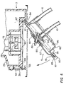
- FIG. 5 shows the controller 3 with the frame 41 in the open or priming position with a disposable pump body 5 installed.
- FIG. 6 is a view of the undersurface of the controller housing; the array consists of switches 69.
- FIGS. 8A-F display the various patterns of bumps that may be molded into the top of the cover plate 87.
- Six representative patterns are illustrated. These patterns operate with the four position square switch array which is illustrated in FIG. 6, but other numbers of switches can be used without departing from the spirit and scope of the invention.
- the bumps protrude from the upper surface of the cover plate 87 as shown in the cross sectional view illustrated in FIG. 8G which is a sectional view of the upper bump in FIG. 8B.
- Each pattern can correspond to a pump body type designed for a particular procedure.
- the bump pattern illustrated in FIG. 8A may designate a pump body which is designed for use in an arthroscopy procedure.
- FIGs. 8A-8F may designate a pump body which is designed for use in a laparoscopy procedure.
- Other bump patterns can correspond to other procedures and some patterns may be reserved for pump bodies which will be designed in the future.
- FIGs. 8A-8F Several illustrative bump patterns are shown in FIGs. 8A-8F; other bump patterns are possible with the four position square array of switches.
- other switch arrays can be used in combination with other bump patterns all without departing from the spirit and scope of the invention.
- the pattern of bumps represents a binary number.
- Binary logic within the controller deciphers which pump body type has been installed by reading which switches have been depressed. With this information, the controller then displays on the LED screen 27 the type of procedure for which the installed body is intended. The user then must confirm that this is the intended procedure (that the correct pump body has been installed) by pressing a confirm button 37 located on the control panel 23 of the controller. Thereafter, the controller selects a motor speed that will generate an initial default fluid pressure that is appropriate for that type of procedure. This pressure will be displayed on the LED screen 27. The user then presses the start button 33 to begin pump operation. The pressure may also be modified by the user by depressing increase button 29 or decrease button 31 during operation. To stop the pump, the user presses the stop button 35.
- the switches 69 located on the underside of the controller 3 are push button switches that have a plastic actuator stem which aligns with the identification bumps 80 on the cover plate 87 of a pump body to selectively operate some, or all, of the switches.
- the switches are wired to a programmable logic device (hereinafter referred to as a PLD) which detects the pattern of closed and open switches.
- a PLD suitable for use with the illustrative embodiment is a XilinxTM programmable logic device distributed by Xilinx, Inc. of San Jose, California.
- the PLD and the remainder of the circuitry is powered by a conventional power supply which may have a safety mechanism, such as a crowbar circuit, that shuts the unit down in the event of a power surge.
- the general layout of the controller electronics is illustrated in FIG. 14.
- the main elements are the programmable logic device 1400, an erasable programmable read only memory (EPROM) 1402, a motor controller 1404, a motor 1406 and a power supply 1408.
- EPROM erasable programmable read only memory
- a remote control 1416 can also be used with the controller.
- the PLD 1400 generates address signals on an address bus 1418 which address signals are applied to the EPROM 1402 and data is returned from the EPROM 1402 to the PLD 1400 on a data bus 1420.
- the PLD can also control the display driver 1412 by means of leads 1422 and receive data from the keyboard 1414 or remote control 1416 by means of leads 1424 and 1426, respectively.
- the PLD 1400 controls the motor 1406 by means of a motor control 1404.
- the motor control 1404 in turn, generates a current drive which operates motor 1406.
- the position of motor 1406 is determined by sensors in motor 1406 and returned, via leads 1432, to PLD 1400 in order to provide closed loop motor control.
- the PLD 1400 is a programmable logic device which electronically reads the pattern of switches which are depressed by the bumps and generates an address word on address bus 1418 which is unique for each switch pattern.
- the pump bodies are arranged so that one of the switches is always depressed when any pump body is present.
- bump 81 shown in FIG. 8A is present in every bump pattern illustrated in FIGs. 8A-8F.
- the absence of a pump body in the controller causes the PLD 1400 to control the LED display driver 1412 to generate the display the word "LOAD" on the LED display 27 and to illuminate the "STOP" button 35.
- This switch is also used for motor safety interlock which will open the return line (not shown) from the motor 1406 should a user open the frame 41 while the controller is in operation.
- the PLD 1400 When one switch is depressed by bump 81, the PLD 1400 generates an address word on bus 1418 based on the positions of the other switches. The address word is, in turn, applied to EPROM 1402 and used to access one of a plurality of lookup tables, permanently programmed into the memory. Each pump body has a dedicated section in the EPROM 1402 where its table is loaded. The EPROM 1402 is addressed by the decoded switch pattern for a particular pump body lookup table.
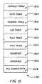
- the general layout of the EPROM 1402 is shown in FIG. 15.
- the EPROM 1500 is divided into eight - 2000 hex byte blocks 1502-1516 in the lower half of the EPROM with the top half 1518 being reserved for PLD configuration data.
- illustrative tables are illustrated for an arthroscopic procedure (table 1504); a general procedure (table 1506); a laparoscopy procedure (table 1508); a procedure requiring a pulsing output (table 1510); a hysteroscopic procedure (table 1512) and two tables reserved for future procedures (tables 1514 and 1516).
- the PLD 1400 When the controller is first powered on, the PLD 1400 is programmed to force the address bus 1418 to address certain memory locations which will cause the display 27 to have the "***'" test pattern displayed followed by the word "LOAD".
- the test pattern "****" and the word "LOAD” is programmed into all the pump body tables 1502-1516 at the same position within each table. Therefore, no matter which table is selected by the switch pattern, the test pattern and "LOAD" word will always be generated. If for any reason an incorrect low address is generated, the error pattern "----" will be displayed as the default table 1502 is blank.
- the address bus 1418 After the controller start routine has finished, the address bus 1418 will be released with the word "LOAD" displayed in display 27 and the controller waits for the first pump body to be loaded.
- the address bus 1418 is directly accessed by the switches through a decoding circuit permanently programmed into the PLD 1400.
- loading a pump body and closing the frame 41 will cause a combination of switches 69 to be activated.
- Three of the four switches directly control address lines in the address bus 1418 and will access that start of one of the seven tables 1504-1516.
- Each table corresponds to one of the pump body types and includes pump body parameters pertinent to a particular pump body, such as, for example, the surgical application, a default starting pressure, and a pressure scale.
- Each table is arranged the same way.
- the first memory location in each table contains the name of the corresponding pump body using a four letter abbreviation.
- the pressure scale parameters stored in the look up tables may include pressure units to be used for each pump body.
- the pressure units for an arthroscopic, laparoscopic, or hysteroscopic application may be millimeters of mercury whereas the units for a pulsatile application for example, may be designated as "low,” “medium,” and "high.”
- the pressure scale parameters also may include a maximum and minimum output pressure value for each of the pump bodies based on the intended medical procedure.
- An arthroscopic application for example, may require pressures in the range from 70 millimeters of mercury to 300 millimeters of mercury.
- a word representing the surgical procedure is sent to LED display drivers to cause a light emitting diode display on the front face of the unit to display the information pertinent to the pump body being used.
- the LED display might generate the word "ARTH” for an arthroscopic procedure, the word “LAP” for a laparoscopic procedure, etc.
- the PLD then waits for the user to depress the confirm procedure button 37 (FIG. 2) on the control panel. Until the confirmation button is pressed, the unit will not proceed.
- a specially programmed portion of the PLD 1400 is driven by a clock.
- the PLD 1400 causes data stored in the lookup tables to be applied to the display driver 1412 using a write pulse derived within the PLD.
- Each lookup table has 16 bytes of data.
- the display driver 1412 operates with two words, an upper word and a lower word.
- the first ten bytes of data in the selected lookup table in EPROM 1402 are output to the display driver 1412 using the write pulse.
- the lower display word is selected and 5 bytes are output, the upper word is then selected After the 10 bytes of display data have been sent, 2 bytes for the default memory location, which is an offset from the starting location of the table, low byte first, then 2 bytes which represent the length of the table (highest table entry) are output to the PLD 1400.
- the PLD When the PLD detects depression of the confirmation button, it controls the LED display to display the default starting pressure value retrieved from the ROM. In particular, data at the default memory location is loaded. For example, 10 bytes are sent to the display driver 1412 for the default pressure. The next 2 bytes retrieved set the motor speed for that pressure. The "STOP" button then is illuminated and the "START” button 33 is not illuminated. The controller is now ready to start the internal electric motor. The motor is actually started when the user depresses the "START" button.
- the PLD When the "START' button is depressed, the PLD transmits a digital word to a motor controller circuit which controls the motor according to the default starting pressure obtained from the lookup table for the installed pump body.
- the default starting pressure is also pre-loaded into an up/down counter.
- the motor controller circuit may, for example, be a commercially-available integrated circuit which that converts the digital signal to a D.C. motor drive current.
- a motor controller circuit suitable for use with the illustrative embodiment is a Brushless D.C. Motor Controller Circuit, part no. MC3035, distributed by Motorola, Inc.
- the motor is a three-phase brushless DC motor which has Hall-effect sensors that sense rotor position. The outputs of the sensors are provided to the PLD 1400 for closed-loop speed control.
- the operation of the unit may be controlled by either the control panel on the face of the unit, or by a remote controller 20 (FIG. 1) that is connected to the unit by a flexible conductive cable 21 which plugs into a receptacle 46 (FIG. 3).
- a key pad on the remote controller may be any known switching device, such as a conductive membrane-type switch and the remote controller preferably includes a start button, a stop button, an increase pressure button and a decrease pressure button and the switches on the remote controller are connected in parallel with the switches on the controller control panel.
- Optocouplers e.g., part no.
- TIL193 from Texas instruments of Dallas, Texas preferably are included on all electrical leads connecting the remote controller 20 to the controller 3 in order to electrically isolate the remote controller 20 from the power supply in the controller 3.
- the electrical isolation prevents or mitigates the chances of an attendant who may be holding the remote controller 20 from receiving an electrical shock in the event that an electrical short circuit develops in the controller 3.
- the user can change the rotational speed of the motor by pressing either the increase button 29 or the decrease button 31.
- the increase and decrease buttons 29 and 31 directly change the RPMs of the motor, thereby changing the output pressure.
- the PLD responds by decrementing the up/down counter to cause a new EPROM address location to be placed on the address bus 1418. Newly addressed information would then be loaded to the display driver 1412 and the motor control 1404.
- the PLD also contains comparator circuits which are pre-loaded with the minimum output pressure value. The decremented up/down counter value is compared to minimum output pressure.
- the decreased value is transmitted to the motor controller to reduce the rotational speed of the motor, thereby decreasing the pump output pressure.
- the decreased value is provided to the LED driver circuitry to cause the LED display to generate a display corresponding to the new value.
- the counter is deselected. A similar routine is followed in the case where the user presses the increase button 29.
- Another important interface between the installed pump body 5 and the controller 3 is the connection of drive power from the electric motor within the controller to the pumping mechanism of the disposable pump.
- the disposable pump body for use with laparoscopic procedures is shown in FIGs. 9A and 9B.
- the incoming fluid line 10 joins the pump body at inlet 112 which is in fluid communication with the hollow shaft 115 of the T-shaped rotating impeller 84. Fluid travels through the hollow shaft, then radially outward through conduits 108 which pass through vanes 85.
- a cylindrical receptacle 109 is molded into the bottom wall of the pump body and holds the hollow shaft 114 of the impeller 84.
- the use of low friction plastic materials at the bearing surfaces of the shaft 114 and the receptacle 115 and the presence of liquid between the contact surfaces prevents the bearing from seizing during use.
- the entire pump body and cover plate are made from the same material as the bearing surfaces.
- an interior wall 98 is molded into the pump body wall which insures that the liquid outlet 110 is positioned near the cover plate 87 of the pumping chamber 86 when the pump body 5 is mounted in the controller.
- the position of the fluid outlet advantageously permits air to be purged from the pump body during a priming procedure.
- the top of the pumping chamber 86 is sealed by a cover plate 87 that is of the same material as the pumping chamber and is joined to the pump chamber by ultrasonic welding or by adhesive.
- the pump drive mechanism must pass through the cover plate 87 to spin the impeller 84 in a manner that preserves the liquid tight integrity of the entire pump bowl.
- a pump drive rod 82 passes through a flexible diaphragm 102 that covers an opening at the center of the cover plate 87.
- the diaphragm 102 is positioned over the hole in the cover plate 87 and is captured against the top surface of the cover plate by flange 106 which is bonded to the top of the cover plate 87 by adhesive or ultrasonic welding.
- the diaphragm 102 is compressed between the top surface of the cover plate 87 and the flange.
- the drive rod 82 passes through a cylindrical sleeve 103 integrally molded into the diaphragm and engages a hole 88 in the impeller 84 as shown in FIG. 9B.
- a collar 104 encircles the sleeve 103 of the diaphragm to maintain the sleeve in secure contact with the surface of the drive rod 82, thereby forming a liquid tight seal.
- An annular rib 100 on the drive rod butts up against the top of the collar 104 to prevent the collar 104 from sliding off the sleeve 103 during shipping, and to prevent the diaphragm 102 from being urged upwardly by the pressure developed in the pump body during activation.
- the drive rod 82 transmits power from the revolving S-shape paddle 71 of the controller 3 to the rotating impeller 84 within the pump chamber 86.
- the impeller 84 and the S-shape paddle 71 share a common axis of rotation.
- the drive rod connects with the impeller and S-shape paddle at points that are offset from the axis of rotation, such that the drive rod is skewed across the axis of rotation. Therefore, as the S-shape paddle rotates under power from the motor, the drive rod rotates, causing the impeller to rotate.
- the diaphragm 102 can be formed with a cross-sectional wave shape (for example, as an S-shape) to reduce stress as the diaphragm flexes due to nutation of the drive rod 82.
- the wave shape would be compressed and oppositely tensioned as rotation occurs. Friction is reduced at this connection through the use of low friction materials in the components, combined with the presence of liquid in the drive rod/impeller connection when the pumping chamber 86 is filled with liquid.
- sloped shaft surface 94A preferably also slopes at a thirty degree angle to contact the outer surface of the shaft 82.
- a searing flange 71 a also may be included on the paddle 71 to prevent the shaft 82 from losing contact with sloped surface 94A.
- FIGs. 12A, 12B and 13A, 13B Pump bodies designed especially for various other medical procedures utilizing the overall design embodiment are shown in FIGs. 12A, 12B and 13A, 13B.
- the pump body illustrated in FIGs. 12A and 12B is designed for use in arthroscopic procedures. It is similar in shape, design and dimension to the laparoscopic pump body described in relation to figures 9A and 9B.
- the arthroscopic pump body 119 employs an impeller 120 having shorter vanes 121 than the impeller 84 used with the laparoscopic pump body described above. This design change optimizes pump performance and utilizes reduced pressures that are desired for arthroscopic use. Since the fluid pressure developed by the pump is related to the vane length and the rotation speed, for a given pump body, the pressure developed by the pump depends on the rotational speed.
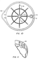
- FIG. 10 is a bottom view of the laparoscopic and arthroscopic pump bodies.
- a set of ribs 116 of increased thickness are formed into the wall during molding to provide structural support to the bottom of the pump body.
- the added structural support prevents pressure variations in the pump output pressure caused by flexure of the bottom wall when the pump body is pressurized during use.
- the added structural support minimizes flexing of the entire assembly to prevent it from dislodging from the paddle.
- pump bodies may be optimized in other ways for particular medical procedures.
- the pump body 124 intended for hysteroscopic use is shown in FIGs, 13A and 13B.
- Pump 124 used for hysteroscopic procedures employs a pump chamber 128 that is not only substantially smaller in diameter than those used for the previously described laparoscopic and arthroscopic procedures, but also has a different shape.
- the smaller pump chamber 128 has a hemispherical shape which helps reduce the amount of air bubble formation that would otherwise occur (in the larger pump chamber) when operating at the lower pressures required in a hysteroscopic procedure. Excessive air bubbles could cause substantial pressure variations within the pump chamber, possibly adversely affecting performance of the pump.
- the hemispherical shape of the pump chamber also helps to reduce fluid stagnation in the pump chamber and the small size limits the maximum pressure to a safe limit.
- the substantially smaller size requires a lesser volume of priming solution that may be clinically controlled.
- the cover plate 132 of the hysteroscopic pump body 124 is dimensioned to maintain interchangeability within the frame 41 of controller 3.
- the overall diameter of the cover plate 132 is the same as the lid used with other pump bodies.
- the cover plate 132 employs a downward extending locating ridge 130 that corresponds to the external diameter flange of the pump bodies used in the other larger pump bodies described above. Therefore, the surface of the locating ridge 130 fits securely within the circular edge 58 of the frame 41. All other characteristics of the hysteroscopic pump body are similar to those described in connection with the laparoscopic pump body.
- FIG. 11 shows a detail of the elevated outlet 110 employed in the pump chambers of the laparoscopic and arthroscopic pump bodies. Wall 98 on the interior of the pump chamber ensures that fluid exits only from the very top of the chamber through outlet 110.
- the hysteroscopic pump body also employs an elevated outlet 136 as shown in FIG. 13B. Fluid discharged from the pump then travels down through outlet port 134 then through the outlet line 12.
- the elevated outlet position on the edge of the pump chamber of the several pump bodies is particularly effective in eliminating air bubbles when priming the pump chamber with fluid during the loading procedure that is described in detail below.
- the user To load a pump body for use with the controller, the user first opens the frame 41 by depressing the release latch 39 allowing the frame 41 to drop to the open position illustrated in FIG. 5 . The user then selects the appropriate pump body for the intended procedure and inserts the pump in the frame by navigating the inlet and outlet lines through the opening 57 of frame 41. The pump body may then be lowered into the frame so that the pump chamber falls within the round edge 58 of the frame and body ridge 83 of the pump body contacts surface 56 of the frame 41. When properly installed the outlet line of the pump body will be oriented towards the back of the controller near the hinge 54 of the frame as shown in FIG. 5.
- the open position of the door and the corresponding angular orientation of the pump body automatically positions the fluid outlet at the highest point of the pump chamber as is shown in FIG. 5.
- liquid travels under the force of gravity to the pump body and enters through the inlet line 10 at the center of the pump chamber.
- the liquid rises through the impeller 84 and fills the chamber 86 starting from the lowest point.
- air is displaced out of the chamber as it is displaced by the rising liquid.
- the outlet With the outlet positioned at the highest point in the chamber the air within the chamber has an outlet through which it can be displaced. All air bubbles are effectively purged from the chamber 86 so that no air bubbles remain trapped in the chamber 86 once the chamber has been completely filled with liquid. This process automatically and effectively primes the pump chamber with liquid with minimum effort by the user.
- the frame 41 is closed upward and engaged with the latch 39.
- the energized controller will identify which type of pump body has been installed by recognizing the sequence of depressed switches (engaged by the sequence of bumps on the top of the cover plate pump body) and controller operation can be initiated as described above.
Landscapes
- Health & Medical Sciences (AREA)
- Heart & Thoracic Surgery (AREA)
- General Health & Medical Sciences (AREA)
- Public Health (AREA)
- Anesthesiology (AREA)
- Hematology (AREA)
- Life Sciences & Earth Sciences (AREA)
- Animal Behavior & Ethology (AREA)
- Engineering & Computer Science (AREA)
- Biomedical Technology (AREA)
- Veterinary Medicine (AREA)
- Vascular Medicine (AREA)
- Pulmonology (AREA)
- External Artificial Organs (AREA)
- Reciprocating Pumps (AREA)
- Infusion, Injection, And Reservoir Apparatuses (AREA)
Description
Claims (15)
- A multipurpose medical irrigation pump system connectable to a source of irrigation fluid (8), the pump system comprising :wherein at least one of the plurality of pump mechanisms comprises a centrifugal pump characterised in that the centrifugal pump includes a nutating drive rod (82) for rotating a rotating vane (84).a motor;a plurality of self-contained, disposable pump mechanisms (5) of different types, each of which is connectable to the irrigation fluid source, the different types of pump mechanisms being configured to produce an irrigation fluid output particularly suited for respective predetermined medical procedures;
anda holder (41) for interchangeably receiving each of the plurality of pump mechanisms (5) and for engaging each pump mechanism with the motor so that the motor drives each pump mechanism; - A pump system as claimed in claim 1 wherein each of the plurality of pump mechanisms comprises identifying indicia (80) unique to a predetermined medical procedure, and the pump system further comprises a controller (3) responsive to the identifying indicia for controlling operation of the motor in a manner compatible with the predetermined medical procedure; preferably the identifying indicia comprising a unique pattern of bumps (80) on the exterior of each pump mechanism; preferably the controller comprising a plurality of switches (69) which are selectively operable by the bumps (80).
- A multipurpose medical irrigation pump system according to claim 1 or 2 wherein each pump mechanism (5) has a priming position that causes substantially all air present in each pump mechanism to be purged from each pump mechanism when each pump mechanism is connected to the irrigation fluid source (8).
- A pump system as claimed in claim 3 wherein each of the plurality of pump mechanisms has a fluid inlet (112) and a fluid outlet (110) and the holder has a priming position for holding each pump mechanism in its position that causes substantially all air present in each pump mechanism to be purged from each pump mechanism when each pump mechanism is connected to the irrigation fluid source.
- A pump system as claimed in claim 4 wherein the fluid outlet (110) in each of the plurality of pump mechanisms (5) is positioned at the highest point in the pump mechanism when each pump mechanism is in the holder in the priming position.
- A pump system as claimed in any of claims 1 to 5 wherein at least one of the interchangeable pump mechanisms (5) is configured to produce an irrigation fluid output particularly suited for a laparoscopic or an arthroscopic or a hysteroscopic medical procedure.
- A pump system as claimed in any of claims 2 to 6 wherein it further comprises a read only memory (1402) having motor parameters for a plurality of predetermined medical procedures stored therein, and optionally further comprises means responsive to the identifying indicia for retrieving motor parameters for the predetermined medical procedure from the read only memory and means responsive to the retrieved parameters for controlling the motor, preferably the motor parameters including a default motor speed, a maximum motor speed and a minimum motor speed.
- A pump system as claimed in any of claims 2 to 7 wherein it further comprises means (27) for generating a visual display identifying the predetermined medical procedure and/or means for preventing the pumping mechanism from operating until a user confirms the predetermined medical procedure.
- A pump system as claimed in any of claims 2 to 8 wherein the holder comprises a controller housing (25) and a U-shaped frame (41) attached to the controller housing by a hinge, the frame having a hole therein for receiving each of the plurality of pump mechanisms, preferably the frame having an open position in which the frame is swung away from the controller housing so that the pumping mechanism may be primed and a closed position in which the frame is held against the housing so that the pumping mechanism may be driven by the motor.
- A disposable pump mechanism connectable to an irrigation fluid source (8) wherein the pump mechanism is for use with a non-disposable drive mechanism and comprises:a centrifugal pump having a rotating vane (84) and a housing (5), both the rotating vane and the housing being sized to produce an irrigation fluid output particularly suited for a predetermined medical procedure;a cover plate (87) attached to the housing (5) adapted to mate with the drive mechanism and does not depend on the predetermined medical procedure for which the pump is suited;
anda pattern of identifying bumps (80) on the cover plate (87), the pattern being unique to the predetermined medical procedure, which bumps may be sensed by the drive mechanism, characterised in that the centrifugal pump has a nutating drive rod (82) for rotating the rotating vane. - A pump mechanism as claimed in claim 10 wherein the housing has a vent for purging air from the housing, preferably the vent being located in a position which permits substantially complete removal of air from the housing, the housing having an inlet and an outlet and the vent being located in the outlet.
- A pump mechanism as claimed in claim 11 wherein the housing is substantially circular and the inlet (112) is located at the center of the housing and the outlet (110) is located at the edge of the housing, preferably the housing having reinforcing ribs on substantially flat areas.
- A pump mechanism as claimed in any of claims 11 or 12 wherein a flexible diaphragm (102) comprises part of the housing, the nutating drive rod (82) extending through the diaphragm, preferably the flexible diaphragm (102) having a cross-section in the form of a double S.
- A pump mechanism as claimed in any of claims 10 to 13 wherein the shape of the housing is suited for one of a plurality of medical procedures.
- A pump system comprising a pump mechanism according to any of claims 10 to 14, an irrigation source (8) and a non-disposable drive mechanism, wherein the irrigation source (8), non-disposable drive mechanism and pump (5) form an unobstructed liquid flow path from an irrigation site to the irrigation source.
Applications Claiming Priority (3)
| Application Number | Priority Date | Filing Date | Title |
|---|---|---|---|
| US69856896A | 1996-08-15 | 1996-08-15 | |
| US698568 | 1996-08-15 | ||
| PCT/US1997/013804 WO1998006446A2 (en) | 1996-08-15 | 1997-08-07 | Medical irrigation pump and system |
Publications (2)
| Publication Number | Publication Date |
|---|---|
| EP0918551A2 EP0918551A2 (en) | 1999-06-02 |
| EP0918551B1 true EP0918551B1 (en) | 2004-11-03 |
Family
ID=24805803
Family Applications (1)
| Application Number | Title | Priority Date | Filing Date |
|---|---|---|---|
| EP97936418A Expired - Lifetime EP0918551B1 (en) | 1996-08-15 | 1997-08-07 | Medical irrigation pump and system |
Country Status (7)
| Country | Link |
|---|---|
| US (2) | US6077246A (en) |
| EP (1) | EP0918551B1 (en) |
| JP (1) | JP4033495B2 (en) |
| AR (2) | AR009247A1 (en) |
| CO (1) | CO4810236A1 (en) |
| DE (1) | DE69731472T2 (en) |
| WO (1) | WO1998006446A2 (en) |
Families Citing this family (215)
| Publication number | Priority date | Publication date | Assignee | Title |
|---|---|---|---|---|
| US6213970B1 (en) | 1993-12-30 | 2001-04-10 | Stryker Corporation | Surgical suction irrigation |
| EP0918551B1 (en) * | 1996-08-15 | 2004-11-03 | Deka Products Limited Partnership | Medical irrigation pump and system |
| CA2213948C (en) | 1996-09-19 | 2006-06-06 | United States Surgical Corporation | Ultrasonic dissector |
| US7776014B2 (en) * | 1998-01-29 | 2010-08-17 | Peter Visconti | Disposable surgical suction/irrigation trumpet valve tube cassette |
| JP4021049B2 (en) * | 1998-05-13 | 2007-12-12 | オリンパス株式会社 | Shochu hemostasis device |
| US6231320B1 (en) * | 1998-06-12 | 2001-05-15 | Abbott Laboratories | Drug infusion pumping cassette latching mechanism |
| US6358224B1 (en) * | 1999-09-24 | 2002-03-19 | Tyco Healthcare Group Lp | Irrigation system for endoscopic surgery |
| US6685667B1 (en) * | 2000-01-11 | 2004-02-03 | C. R. Bard, Inc. | Electrically powered surgical irrigator |
| US6497676B1 (en) | 2000-02-10 | 2002-12-24 | Baxter International | Method and apparatus for monitoring and controlling peritoneal dialysis therapy |
| DE20009786U1 (en) * | 2000-05-31 | 2000-10-19 | Taufig, Ahmmed Ziah, Dr., 51109 Köln | Liposuction device |
| US6652488B1 (en) * | 2000-09-11 | 2003-11-25 | Stryker Corporation | Surgical suction irrigator |
| ES2278785T3 (en) * | 2000-09-22 | 2007-08-16 | C.R. Bard, Inc. | SURGICAL IRRIGATION SYSTEM. |
| US6958058B1 (en) | 2001-05-18 | 2005-10-25 | Medsafe Inc. | Methods and devices for pumping fluid and performing surgical procedures |
| ITBO20010623A1 (en) * | 2001-10-10 | 2003-04-10 | Castellini Spa | DENTAL UNIT |
| US10285694B2 (en) | 2001-10-20 | 2019-05-14 | Covidien Lp | Surgical stapler with timer and feedback display |
| US7464847B2 (en) | 2005-06-03 | 2008-12-16 | Tyco Healthcare Group Lp | Surgical stapler with timer and feedback display |
| US20030125662A1 (en) | 2002-01-03 | 2003-07-03 | Tuan Bui | Method and apparatus for providing medical treatment therapy based on calculated demand |
| DE20211555U1 (en) | 2002-07-12 | 2002-11-28 | Peln, Andreas, 23627 Groß Grönau | Surgical device for removing tissue cells from a biological structure |
| US7238164B2 (en) | 2002-07-19 | 2007-07-03 | Baxter International Inc. | Systems, methods and apparatuses for pumping cassette-based therapies |
| US20050267401A1 (en) * | 2004-05-25 | 2005-12-01 | Sherwood Services, Ag. | Safety interlock system for an enteral feeding pump |
| AU2004232858B2 (en) | 2003-04-23 | 2009-07-09 | Mannkind Corporation | Hydraulically actuated pump for long duration medicament administration |
| GB2403148C2 (en) | 2003-06-23 | 2013-02-13 | Microsulis Ltd | Radiation applicator |
| WO2005099374A2 (en) * | 2004-04-05 | 2005-10-27 | Genesee Biomedical, Inc. | Method and apparatus for the surgical treatment of congestive heart failure |
| WO2006014425A1 (en) | 2004-07-02 | 2006-02-09 | Biovalve Technologies, Inc. | Methods and devices for delivering glp-1 and uses thereof |
| GB2415630C2 (en) | 2004-07-02 | 2007-03-22 | Microsulis Ltd | Radiation applicator and method of radiating tissue |
| WO2006034436A2 (en) | 2004-09-21 | 2006-03-30 | Stout Medical Group, L.P. | Expandable support device and method of use |
| US9433730B2 (en) | 2013-03-14 | 2016-09-06 | Bayer Healthcare Llc | Fluid mixing control device for a multi-fluid delivery system |
| US9011377B2 (en) | 2008-11-05 | 2015-04-21 | Bayer Medical Care Inc. | Fluid mixing control device for a multi-fluid delivery system |
| US7766883B2 (en) | 2007-10-30 | 2010-08-03 | Medrad, Inc. | System and method for proportional mixing and continuous delivery of fluids |
| AU2006255303B2 (en) | 2005-06-03 | 2011-12-15 | Covidien Lp | Battery powered surgical instrument |
| US11291443B2 (en) | 2005-06-03 | 2022-04-05 | Covidien Lp | Surgical stapler with timer and feedback display |
| GB2434314B (en) | 2006-01-03 | 2011-06-15 | Microsulis Ltd | Microwave applicator with dipole antenna |
| WO2007009107A2 (en) | 2005-07-14 | 2007-01-18 | Stout Medical Group, P.L. | Expandable support device and method of use |
| US20090092507A1 (en) * | 2005-08-05 | 2009-04-09 | Ramirez Jr Emilio A | Fluid pump systems |
| US8585379B2 (en) | 2005-08-05 | 2013-11-19 | Molon Motor And Coil Corporation | Peristaltic pump that is resistant to torques and vibrations |
| US8469682B2 (en) * | 2005-08-05 | 2013-06-25 | Molon Motor And Coil Corporation | Peristaltic pump with torque relief |
| US20070031272A1 (en) * | 2005-08-05 | 2007-02-08 | Molon Motor And Coil Corporation | Peristaltic pump |
| US8380126B1 (en) | 2005-10-13 | 2013-02-19 | Abbott Medical Optics Inc. | Reliable communications for wireless devices |
| US8565839B2 (en) | 2005-10-13 | 2013-10-22 | Abbott Medical Optics Inc. | Power management for wireless devices |
| US8052644B2 (en) * | 2005-12-14 | 2011-11-08 | Stryker Corporation | Surgical irrigation system |
| WO2007076376A2 (en) * | 2005-12-19 | 2007-07-05 | Stout Medical Group, L.P. | Expandable delivery device |
| US8079836B2 (en) * | 2006-03-01 | 2011-12-20 | Novartis Ag | Method of operating a peristaltic pump |
| US20070217919A1 (en) * | 2006-03-14 | 2007-09-20 | Alcon, Inc. | Peristaltic pump |
| AU2007233231B2 (en) | 2006-03-30 | 2011-02-24 | Mannkind Corporation | Multi-cartridge fluid delivery device |
| WO2007131002A2 (en) | 2006-05-01 | 2007-11-15 | Stout Medical Group, L.P. | Expandable support device and method of use |
| US9522221B2 (en) | 2006-11-09 | 2016-12-20 | Abbott Medical Optics Inc. | Fluidics cassette for ocular surgical system |
| US8414534B2 (en) * | 2006-11-09 | 2013-04-09 | Abbott Medical Optics Inc. | Holding tank devices, systems, and methods for surgical fluidics cassette |
| US9295765B2 (en) * | 2006-11-09 | 2016-03-29 | Abbott Medical Optics Inc. | Surgical fluidics cassette supporting multiple pumps |
| US10959881B2 (en) | 2006-11-09 | 2021-03-30 | Johnson & Johnson Surgical Vision, Inc. | Fluidics cassette for ocular surgical system |
| US8491528B2 (en) | 2006-11-09 | 2013-07-23 | Abbott Medical Optics Inc. | Critical alignment of fluidics cassettes |
| US20080132763A1 (en) * | 2006-12-04 | 2008-06-05 | Isaacson Keith B | Apparatus And Method For An Endoscope Pump |
| US7731689B2 (en) | 2007-02-15 | 2010-06-08 | Baxter International Inc. | Dialysis system having inductive heating |
| US8870812B2 (en) | 2007-02-15 | 2014-10-28 | Baxter International Inc. | Dialysis system having video display with ambient light adjustment |
| US8558964B2 (en) | 2007-02-15 | 2013-10-15 | Baxter International Inc. | Dialysis system having display with electromagnetic compliance (“EMC”) seal |
| US7998115B2 (en) * | 2007-02-15 | 2011-08-16 | Baxter International Inc. | Dialysis system having optical flowrate detection |
| US8361023B2 (en) | 2007-02-15 | 2013-01-29 | Baxter International Inc. | Dialysis system with efficient battery back-up |
| US7431188B1 (en) | 2007-03-15 | 2008-10-07 | Tyco Healthcare Group Lp | Surgical stapling apparatus with powered articulation |
| US8800837B2 (en) | 2007-04-13 | 2014-08-12 | Covidien Lp | Powered surgical instrument |
| US7950560B2 (en) | 2007-04-13 | 2011-05-31 | Tyco Healthcare Group Lp | Powered surgical instrument |
| US11259801B2 (en) | 2007-04-13 | 2022-03-01 | Covidien Lp | Powered surgical instrument |
| US20080255413A1 (en) | 2007-04-13 | 2008-10-16 | Michael Zemlok | Powered surgical instrument |
| US20110088151A1 (en) * | 2007-04-17 | 2011-04-21 | Semra Peksoz | Firefighter's turnout coat with seamless collar |
| US7823760B2 (en) | 2007-05-01 | 2010-11-02 | Tyco Healthcare Group Lp | Powered surgical stapling device platform |
| US7931660B2 (en) | 2007-05-10 | 2011-04-26 | Tyco Healthcare Group Lp | Powered tacker instrument |
| US7833196B2 (en) | 2007-05-21 | 2010-11-16 | Asante Solutions, Inc. | Illumination instrument for an infusion pump |
| US7892199B2 (en) | 2007-05-21 | 2011-02-22 | Asante Solutions, Inc. | Occlusion sensing for an infusion pump |
| US7981102B2 (en) * | 2007-05-21 | 2011-07-19 | Asante Solutions, Inc. | Removable controller for an infusion pump |
| US7794426B2 (en) | 2007-05-21 | 2010-09-14 | Asante Solutions, Inc. | Infusion pump system with contamination-resistant features |
| US10363166B2 (en) | 2007-05-24 | 2019-07-30 | Johnson & Johnson Surgical Vision, Inc. | System and method for controlling a transverse phacoemulsification system using sensed data |
| US10596032B2 (en) * | 2007-05-24 | 2020-03-24 | Johnson & Johnson Surgical Vision, Inc. | System and method for controlling a transverse phacoemulsification system with a footpedal |
| US10485699B2 (en) | 2007-05-24 | 2019-11-26 | Johnson & Johnson Surgical Vision, Inc. | Systems and methods for transverse phacoemulsification |
| US8162633B2 (en) * | 2007-08-02 | 2012-04-24 | Abbott Medical Optics Inc. | Volumetric fluidics pump with translating shaft path |
| US10342701B2 (en) | 2007-08-13 | 2019-07-09 | Johnson & Johnson Surgical Vision, Inc. | Systems and methods for phacoemulsification with vacuum based pumps |
| US8083503B2 (en) | 2007-09-27 | 2011-12-27 | Curlin Medical Inc. | Peristaltic pump assembly and regulator therefor |
| US8062008B2 (en) | 2007-09-27 | 2011-11-22 | Curlin Medical Inc. | Peristaltic pump and removable cassette therefor |
| US7934912B2 (en) | 2007-09-27 | 2011-05-03 | Curlin Medical Inc | Peristaltic pump assembly with cassette and mounting pin arrangement |
| US20090090201A1 (en) * | 2007-10-05 | 2009-04-09 | Tyco Healthcare Group Lp | Nutating Gear Drive Mechanism for Surgical Devices |
| US7922063B2 (en) | 2007-10-31 | 2011-04-12 | Tyco Healthcare Group, Lp | Powered surgical instrument |
| US20090125014A1 (en) * | 2007-11-14 | 2009-05-14 | Bouthillier Robert J | Thermal Ablation System |
| US9026370B2 (en) | 2007-12-18 | 2015-05-05 | Hospira, Inc. | User interface improvements for medical devices |
| US8986253B2 (en) | 2008-01-25 | 2015-03-24 | Tandem Diabetes Care, Inc. | Two chamber pumps and related methods |
| IT1391274B1 (en) * | 2008-08-08 | 2011-12-01 | Medica S R L Ab | IRRIGATION AND SUCTION SYSTEM, IN PARTICULAR FOR LAPAROSCOPIC SURGERY |
| US7959598B2 (en) | 2008-08-20 | 2011-06-14 | Asante Solutions, Inc. | Infusion pump systems and methods |
| US8408421B2 (en) | 2008-09-16 | 2013-04-02 | Tandem Diabetes Care, Inc. | Flow regulating stopcocks and related methods |
| CA2737461A1 (en) | 2008-09-19 | 2010-03-25 | Tandem Diabetes Care, Inc. | Solute concentration measurement device and related methods |
| CA2733825C (en) | 2008-11-07 | 2017-09-12 | Abbott Medical Optics Inc. | Method for programming foot pedal settings and controlling performance through foot pedal variation |
| CA2733827C (en) * | 2008-11-07 | 2017-09-12 | Dung Ma | Semi-automatic device calibration |
| WO2010054145A1 (en) | 2008-11-07 | 2010-05-14 | Abbott Medical Optics Inc. | Surgical cassette apparatus |
| US9795507B2 (en) | 2008-11-07 | 2017-10-24 | Abbott Medical Optics Inc. | Multifunction foot pedal |
| EP3954345B1 (en) | 2008-11-07 | 2023-11-22 | Johnson & Johnson Surgical Vision, Inc. | Adjustable foot pedal control for ophthalmic surgery |
| WO2010054225A2 (en) | 2008-11-07 | 2010-05-14 | Abbott Medical Optics Inc. | Automatically switching different aspiration levels and/or pumps to an ocular probe |
| AU2009313384B2 (en) | 2008-11-07 | 2015-06-11 | Johnson & Johnson Surgical Vision, Inc. | Automatically pulsing different aspiration levels to an ocular probe |
| AU2009313413B2 (en) | 2008-11-07 | 2015-01-22 | Johnson & Johnson Surgical Vision, Inc. | Controlling of multiple pumps |
| US20100211176A1 (en) | 2008-11-12 | 2010-08-19 | Stout Medical Group, L.P. | Fixation device and method |
| WO2010056895A1 (en) | 2008-11-12 | 2010-05-20 | Stout Medical Group, L.P. | Fixation device and method |
| US8360982B2 (en) * | 2008-12-05 | 2013-01-29 | General Electric Company | Method and apparatus for operating a micromotor in a fluid using a moisture barrier |
| US9360017B2 (en) * | 2009-01-23 | 2016-06-07 | Grundfos Pumps Corporation | Pump assembly having an integrated user interface |
| US9492317B2 (en) | 2009-03-31 | 2016-11-15 | Abbott Medical Optics Inc. | Cassette capture mechanism |
| US8821514B2 (en) | 2009-06-08 | 2014-09-02 | Covidien Lp | Powered tack applier |
| MX2012000100A (en) | 2009-07-01 | 2012-04-02 | Fresenius Med Care Hldg Inc | Drug delivery devices and related systems and methods. |
| EP2724739B1 (en) | 2009-07-30 | 2015-07-01 | Tandem Diabetes Care, Inc. | Portable infusion pump system |
| US9072540B2 (en) | 2009-08-12 | 2015-07-07 | Boston Scientific Limited | Adaptive tubing cassettes for use in connection with interventional catheter assemblies |
| US8388582B2 (en) | 2009-08-12 | 2013-03-05 | Medrad, Inc. | Systems and methods for operating interventional catheters using a common operating console and adaptive interface components |
| GB2474233A (en) * | 2009-10-06 | 2011-04-13 | Uk Investments Associates Llc | Cooling pump comprising a detachable head portion |
| US8876757B2 (en) * | 2009-11-12 | 2014-11-04 | Abbott Medical Optics Inc. | Fluid level detection system |
| US8619911B2 (en) | 2009-12-15 | 2013-12-31 | Stmicroelectronics International N.V. | Quadrature signal decoding using a driver |
| US8654895B2 (en) * | 2009-12-15 | 2014-02-18 | Stmicroelectronics International N.V. | Frequency modulated signal decoding using a driver |
| US8394081B2 (en) | 2010-01-29 | 2013-03-12 | Kci Licensing, Inc. | Wound treatment apparatuses and methods for controlled delivery of fluids to a wound |
| US8535380B2 (en) | 2010-05-13 | 2013-09-17 | Stout Medical Group, L.P. | Fixation device and method |
| USD669165S1 (en) | 2010-05-27 | 2012-10-16 | Asante Solutions, Inc. | Infusion pump |
| WO2012027490A2 (en) | 2010-08-24 | 2012-03-01 | Stout Medical Group, L.P. | Support device and method for use |
| US9149286B1 (en) | 2010-11-12 | 2015-10-06 | Flexmedex, LLC | Guidance tool and method for use |
| EP2671176B1 (en) | 2011-01-31 | 2019-01-09 | Fresenius Medical Care Holdings, Inc. | Preventing over-delivery of drug |
| EP2673018B1 (en) | 2011-02-08 | 2019-04-10 | Fresenius Medical Care Holdings, Inc. | Magnetic sensors and related systems and methods |
| EP2707049B1 (en) * | 2011-05-12 | 2019-07-03 | Bayer Healthcare LLC | Fluid injection system having various systems for controlling an injection procedure |
| WO2013028497A1 (en) | 2011-08-19 | 2013-02-28 | Hospira, Inc. | Systems and methods for a graphical interface including a graphical representation of medical data |
| EP2747682A4 (en) | 2011-08-23 | 2015-01-21 | Flexmedex Llc | Tissue removal device and method |
| US8808230B2 (en) | 2011-09-07 | 2014-08-19 | Asante Solutions, Inc. | Occlusion detection for an infusion pump system |
| HK1199851A1 (en) | 2011-09-21 | 2015-07-24 | Bayer Healthcare Llc | Continuous multi-fluid pump device, drive and actuating system and method |
| US10022498B2 (en) | 2011-12-16 | 2018-07-17 | Icu Medical, Inc. | System for monitoring and delivering medication to a patient and method of using the same to minimize the risks associated with automated therapy |
| US20150272622A1 (en) | 2011-12-22 | 2015-10-01 | Previvo Genetics, Llc | Recovery and processing of human embryos formed in vivo |
| US9216037B2 (en) | 2013-06-21 | 2015-12-22 | Previvo Genetics, Llc | Uterine lavage for embryo retrieval |
| US9282995B2 (en) | 2011-12-22 | 2016-03-15 | Previvo Genetics, Llc | Recovery and processing of human embryos formed in vivo |
| US9700457B2 (en) | 2012-03-17 | 2017-07-11 | Abbott Medical Optics Inc. | Surgical cassette |
| EP2830687B1 (en) | 2012-03-30 | 2019-07-24 | ICU Medical, Inc. | Air detection system and method for detecting air in a pump of an infusion system |
| US9144646B2 (en) | 2012-04-25 | 2015-09-29 | Fresenius Medical Care Holdings, Inc. | Vial spiking devices and related assemblies and methods |
| US9180242B2 (en) | 2012-05-17 | 2015-11-10 | Tandem Diabetes Care, Inc. | Methods and devices for multiple fluid transfer |
| US9555186B2 (en) | 2012-06-05 | 2017-01-31 | Tandem Diabetes Care, Inc. | Infusion pump system with disposable cartridge having pressure venting and pressure feedback |
| US9381297B2 (en) | 2012-06-07 | 2016-07-05 | Tandem Diabetes Care, Inc. | Sealed infusion device with electrical connector port |
| DE102012105919A1 (en) * | 2012-07-03 | 2014-06-12 | B. Braun Avitum Ag | Tubular roller pump with pivoting lid and medical device for extracorporeal blood treatment with tube roller pump |
| US9710610B2 (en) | 2012-07-25 | 2017-07-18 | Covidien Lp | Enteral feeding pump with flow adjustment |
| CA3089257C (en) | 2012-07-31 | 2023-07-25 | Icu Medical, Inc. | Patient care system for critical medications |
| US9888956B2 (en) | 2013-01-22 | 2018-02-13 | Angiodynamics, Inc. | Integrated pump and generator device and method of use |
| US9173998B2 (en) | 2013-03-14 | 2015-11-03 | Tandem Diabetes Care, Inc. | System and method for detecting occlusions in an infusion pump |
| CA2913421C (en) | 2013-05-24 | 2022-02-15 | Hospira, Inc. | Multi-sensor infusion system for detecting air or an occlusion in the infusion system |
| AU2014274122A1 (en) | 2013-05-29 | 2016-01-21 | Icu Medical, Inc. | Infusion system and method of use which prevents over-saturation of an analog-to-digital converter |
| ES2838450T3 (en) | 2013-05-29 | 2021-07-02 | Icu Medical Inc | Infusion set that uses one or more sensors and additional information to make an air determination relative to the infusion set |
| US9561324B2 (en) | 2013-07-19 | 2017-02-07 | Bigfoot Biomedical, Inc. | Infusion pump system and method |
| ES3010316T3 (en) | 2013-09-24 | 2025-04-02 | Kpr Us Llc | Feeding set and enteral feeding pump |
| US10569015B2 (en) | 2013-12-02 | 2020-02-25 | Bigfoot Biomedical, Inc. | Infusion pump system and method |
| JP5901855B2 (en) * | 2013-12-26 | 2016-04-13 | オリンパス株式会社 | Pneumoperitoneum |
| MX390270B (en) | 2014-01-10 | 2025-03-20 | Bayer Healthcare Llc | CONNECTOR FOR SINGLE-USE DISPOSABLE ASSEMBLY. |
| EP3110474B1 (en) | 2014-02-28 | 2019-12-18 | ICU Medical, Inc. | Infusion system and method which utilizes dual wavelength optical air-in-line detection |
| JP2017517302A (en) | 2014-05-29 | 2017-06-29 | ホスピーラ インコーポレイテッド | Infusion system and pump with configurable closed loop delivery rate catchup |
| US11344668B2 (en) | 2014-12-19 | 2022-05-31 | Icu Medical, Inc. | Infusion system with concurrent TPN/insulin infusion |
| RU2714926C2 (en) | 2015-01-09 | 2020-02-21 | БАЙЕР ХелсКер ЛЛСи | Multiple fluid delivery system with multi-use disposable set and features thereof |
| US10850024B2 (en) | 2015-03-02 | 2020-12-01 | Icu Medical, Inc. | Infusion system, device, and method having advanced infusion features |
| US9878097B2 (en) | 2015-04-29 | 2018-01-30 | Bigfoot Biomedical, Inc. | Operating an infusion pump system |
| MX383409B (en) | 2015-07-02 | 2025-03-13 | Northgate Tech Inc | GAS RECIRCULATION SYSTEM. |
| US10660691B2 (en) | 2015-10-07 | 2020-05-26 | Angiodynamics, Inc. | Multiple use subassembly with integrated fluid delivery system for use with single or dual-lumen peristaltic tubing |
| HK1257215A1 (en) | 2016-01-05 | 2019-10-18 | Bigfoot Biomedical, Inc. | Operating multi-modal medicine delivery systems |
| US10610643B2 (en) | 2016-01-14 | 2020-04-07 | Bigfoot Biomedical, Inc. | Occlusion resolution in medication delivery devices, systems, and methods |
| USD809134S1 (en) | 2016-03-10 | 2018-01-30 | Bigfoot Biomedical, Inc. | Infusion pump assembly |
| EP3454922B1 (en) | 2016-05-13 | 2022-04-06 | ICU Medical, Inc. | Infusion pump system with common line auto flush |
| AU2017277804B2 (en) | 2016-06-10 | 2022-05-26 | Icu Medical, Inc. | Acoustic flow sensor for continuous medication flow measurements and feedback control of infusion |
| EP3871707B1 (en) | 2016-06-15 | 2026-03-25 | Bayer Healthcare LLC | Syringe for a multi-use disposable system |
| US11090417B2 (en) | 2016-09-20 | 2021-08-17 | Medela Holding Ag | Suctioning and supply device with drive unit and connecting part |
| CN109789251B (en) | 2016-09-20 | 2021-12-28 | 美德乐控股公司 | Device for aspirating body fluids and for delivering substances |
| US10426896B2 (en) | 2016-09-27 | 2019-10-01 | Bigfoot Biomedical, Inc. | Medicine injection and disease management systems, devices, and methods |
| US11096624B2 (en) | 2016-12-12 | 2021-08-24 | Bigfoot Biomedical, Inc. | Alarms and alerts for medication delivery devices and systems |
| USD836769S1 (en) | 2016-12-12 | 2018-12-25 | Bigfoot Biomedical, Inc. | Insulin delivery controller |
| EP3592966B1 (en) * | 2017-03-06 | 2021-06-09 | HELLA GmbH & Co. KGaA | Purge pump system with emergency stop |
| US11311295B2 (en) | 2017-05-15 | 2022-04-26 | Covidien Lp | Adaptive powered stapling algorithm with calibration factor |
| USD839294S1 (en) | 2017-06-16 | 2019-01-29 | Bigfoot Biomedical, Inc. | Display screen with graphical user interface for closed-loop medication delivery |
| US11179516B2 (en) | 2017-06-22 | 2021-11-23 | Baxter International Inc. | Systems and methods for incorporating patient pressure into medical fluid delivery |
| US11504472B2 (en) | 2017-07-06 | 2022-11-22 | Quasuras, Inc. | Medical pump with flow control |
| US11389088B2 (en) | 2017-07-13 | 2022-07-19 | Bigfoot Biomedical, Inc. | Multi-scale display of blood glucose information |
| US10987104B2 (en) | 2017-10-30 | 2021-04-27 | Covidien Lp | Apparatus for endoscopic procedures |
| US11207066B2 (en) | 2017-10-30 | 2021-12-28 | Covidien Lp | Apparatus for endoscopic procedures |
| US12185949B2 (en) | 2017-10-30 | 2025-01-07 | Covidien Lp | Apparatus for endoscopic procedures |
| US10089055B1 (en) | 2017-12-27 | 2018-10-02 | Icu Medical, Inc. | Synchronized display of screen content on networked devices |
| US11497490B2 (en) | 2018-07-09 | 2022-11-15 | Covidien Lp | Powered surgical devices including predictive motor control |
| US12137902B2 (en) | 2018-07-25 | 2024-11-12 | Covidien Lp | Adaptive anti-twitch algorithm for powered surgical devices |
| CN109350789B (en) * | 2018-09-21 | 2020-12-15 | 贵州省习水县人民医院 | A clinical care device |
| US11471660B2 (en) * | 2018-10-25 | 2022-10-18 | Covidien Lp | Vacuum driven suction and irrigation system |
| US11197734B2 (en) | 2018-10-30 | 2021-12-14 | Covidien Lp | Load sensing devices for use in surgical instruments |
| JP2022506545A (en) * | 2018-11-08 | 2022-01-17 | ネオトラクト インコーポレイテッド | Catheter to treat bleeding |
| US11369372B2 (en) | 2018-11-28 | 2022-06-28 | Covidien Lp | Surgical stapler adapter with flexible cable assembly, flexible fingers, and contact clips |
| US11202635B2 (en) | 2019-02-04 | 2021-12-21 | Covidien Lp | Programmable distal tilt position of end effector for powered surgical devices |
| US11376006B2 (en) | 2019-02-06 | 2022-07-05 | Covidien Lp | End effector force measurement with digital drive circuit |
| CN109847128B (en) * | 2019-03-07 | 2024-08-23 | 江苏赛腾医疗科技有限公司 | A blood pump and cardiopulmonary bypass system |
| US11219461B2 (en) | 2019-03-08 | 2022-01-11 | Covidien Lp | Strain gauge stabilization in a surgical device |
| US11883626B2 (en) | 2019-06-27 | 2024-01-30 | Boston Scientific Scimed, Inc. | Detection of an endoscope to a fluid management system |
| US12564677B2 (en) | 2019-10-21 | 2026-03-03 | Tandem Diabetes Care, Inc. | Systems and methods for automated insulin delivery response to inaccurate or missed glucose values |
| CN118787807A (en) | 2019-10-30 | 2024-10-18 | 波士顿科学医疗设备有限公司 | Fluid Monitoring System |
| WO2021094352A1 (en) * | 2019-11-12 | 2021-05-20 | Medela Holding Ag | Device for the extraction of body fluid by suction |
| US11278671B2 (en) | 2019-12-04 | 2022-03-22 | Icu Medical, Inc. | Infusion pump with safety sequence keypad |
| EP4070303B1 (en) * | 2019-12-06 | 2026-05-13 | Quasuras, Inc. | Training cartridge for medical pump systems |
| AU2020410412A1 (en) | 2019-12-17 | 2022-08-11 | Johnson & Johnson Surgical Vision, Inc. | Systems and methods for providing a pulseless peristaltic pump |
| CA3169405A1 (en) | 2020-01-30 | 2021-08-05 | Boston Scientific Scimed, Inc. | Fluid management system and method for controlling intracavity pressure |
| US11817197B2 (en) | 2020-02-07 | 2023-11-14 | Quasuras, Inc. | Medical pump electronic pairing with device |
| US11458244B2 (en) | 2020-02-07 | 2022-10-04 | Covidien Lp | Irrigating surgical apparatus with positive pressure fluid |
| US11553913B2 (en) | 2020-02-11 | 2023-01-17 | Covidien Lp | Electrically-determining tissue cut with surgical stapling apparatus |
| KR102840079B1 (en) | 2020-02-27 | 2025-08-01 | 보스톤 싸이엔티픽 싸이메드 인코포레이티드 | Method for controlling parameters of fluid management and medical device systems |
| US12029470B2 (en) | 2020-05-21 | 2024-07-09 | Covidien Lp | Simultaneous RF monopolar calibration using a shared return electrode |
| EP4157387B1 (en) | 2020-06-02 | 2025-09-24 | Stryker Corporation | Modular, multi-specialty fluid pump |
| US11622768B2 (en) | 2020-07-13 | 2023-04-11 | Covidien Lp | Methods and structure for confirming proper assembly of powered surgical stapling systems |
| WO2022020184A1 (en) | 2020-07-21 | 2022-01-27 | Icu Medical, Inc. | Fluid transfer devices and methods of use |
| KR20250144498A (en) | 2020-07-30 | 2025-10-10 | 보스톤 싸이엔티픽 싸이메드 인코포레이티드 | Fluid management system with integrated laser fiber cooling |
| US12193884B2 (en) | 2020-11-17 | 2025-01-14 | Covidien Lp | Contactless force measurement of motor torque in powered surgical device |
| US11653919B2 (en) | 2020-11-24 | 2023-05-23 | Covidien Lp | Stapler line reinforcement continuity |
| US11744580B2 (en) | 2020-11-24 | 2023-09-05 | Covidien Lp | Long stapler reloads with continuous cartridge |
| US11135360B1 (en) | 2020-12-07 | 2021-10-05 | Icu Medical, Inc. | Concurrent infusion with common line auto flush |
| WO2022225820A1 (en) | 2021-04-19 | 2022-10-27 | Baxter International Inc. | Peritoneal dialysis system using ideal gas law |
| US12016556B2 (en) | 2021-05-03 | 2024-06-25 | Covidien Lp | Handheld electromechanical surgical system |
| US11684362B2 (en) | 2021-06-07 | 2023-06-27 | Covidien Lp | Handheld electromechanical surgical system |
| US11771432B2 (en) | 2021-06-29 | 2023-10-03 | Covidien Lp | Stapling and cutting to default values in the event of strain gauge data integrity loss |
| US12161341B2 (en) | 2021-09-07 | 2024-12-10 | Covidien Lp | Slow speed staple and staple relaxation for stapling optimization |
| US12599716B2 (en) | 2021-10-12 | 2026-04-14 | Icu Medical, Inc. | Intravenous infusion pump with cassette insertion and pump control user interface |
| USD1091564S1 (en) | 2021-10-13 | 2025-09-02 | Icu Medical, Inc. | Display screen or portion thereof with graphical user interface for a medical device |
| AU2022407460A1 (en) | 2021-12-10 | 2024-06-27 | Icu Medical, Inc. | Medical fluid compounding systems with coordinated flow control |
| US11832823B2 (en) | 2022-02-08 | 2023-12-05 | Covidien Lp | Determination of anvil release during anastomosis |
| US12613134B2 (en) | 2022-03-31 | 2026-04-28 | Covidien Lp | System and method for color sensor characterization, calibration and threshold-setting |
| US12616474B2 (en) | 2023-10-17 | 2026-05-05 | Covidien Lp | Robotic or powered surgical stapler with predictive stapling end stop |
| USD1084316S1 (en) | 2023-11-20 | 2025-07-15 | Angiodynamics, Inc. | Ferrule |
Family Cites Families (24)
| Publication number | Priority date | Publication date | Assignee | Title |
|---|---|---|---|---|
| US2773453A (en) * | 1952-09-12 | 1956-12-11 | Gemeinhardt William | Rotary pumps |
| US3927955A (en) | 1971-08-23 | 1975-12-23 | East West Medical Products Inc | Medical cassette pump |
| US4635621A (en) | 1982-12-01 | 1987-01-13 | Snyder Laboratories, Inc. | Lavage system with replaceable pump |
| US4537561A (en) * | 1983-02-24 | 1985-08-27 | Medical Technology, Ltd. | Peristaltic infusion pump and disposable cassette for use therewith |
| US4986821A (en) * | 1986-05-28 | 1991-01-22 | Kamen Dean L | Drop detection housing with positive tactile signaling |
| ES2036616T3 (en) * | 1987-05-01 | 1993-06-01 | Abbott Laboratories | DISPOSABLE CASSETTE OF PUMPING CHAMBER FOR INFUSION OF FLUIDS AND ITS DRIVING MECHANISM. |
| US4940457A (en) * | 1987-12-23 | 1990-07-10 | Snyder Laboratories, Inc. | Irrigation system for use during arthroscopy |
| US4886431A (en) * | 1988-04-29 | 1989-12-12 | Cole-Parmer Instrument Company | Peristaltic pump having independently adjustable cartridges |
| US5178515A (en) * | 1989-05-22 | 1993-01-12 | Olympus Optical Co., Ltd. | Medical pump |
| DE69114423T2 (en) * | 1990-04-04 | 1996-06-20 | Ferton Holding | DEVICE FOR RINSING OR CONTINUOUSLY DRAINING THE TISSUE OR BODY CAVES OF THE HUMAN OR ANIMAL ORGANISM. |
| US5431627A (en) * | 1993-11-12 | 1995-07-11 | Abbott Laboratories | Cassette identification system for use with a multi-program drug infusion pump |
| US5531697A (en) * | 1994-04-15 | 1996-07-02 | Sims Deltec, Inc. | Systems and methods for cassette identification for drug pumps |
| JPH08506984A (en) * | 1993-12-22 | 1996-07-30 | バクスター、インターナショナル、インコーポレイテッド | Self-priming drip chamber with improved visibility |
| US5464391A (en) * | 1994-03-03 | 1995-11-07 | Northgate Technologies Inc. | Irrigation system for a surgical site |
| US5460490A (en) * | 1994-05-19 | 1995-10-24 | Linvatec Corporation | Multi-purpose irrigation/aspiration pump system |
| US5554155A (en) * | 1994-06-03 | 1996-09-10 | Johns Hopkins University | Fiber optic pick manipulator |
| US5647852A (en) * | 1995-01-31 | 1997-07-15 | Zimmer, Inc. | Lavage system including a cassette assembly |
| US5554115A (en) | 1995-04-07 | 1996-09-10 | Abbott Laboratories | Sensor for measuring pressures in a cassette pump proximal and distal to a pumping chamber |
| US5578012A (en) * | 1995-04-24 | 1996-11-26 | Deka Products Limited Partnership | Medical fluid pump |
| US5800396A (en) * | 1995-11-15 | 1998-09-01 | Alcon Laboratories, Inc. | Surgical cassette adapter |
| US5788671A (en) * | 1996-08-14 | 1998-08-04 | Sims Deltec, Inc. | Reusable cassette housings and methods |
| EP0918551B1 (en) * | 1996-08-15 | 2004-11-03 | Deka Products Limited Partnership | Medical irrigation pump and system |
| US5746719A (en) * | 1996-10-25 | 1998-05-05 | Arthur D. Little, Inc. | Fluid flow control system incorporating a disposable pump cartridge |
| AU9028498A (en) * | 1997-08-22 | 1999-03-16 | Deka Products Limited Partnership | System, method and cassette for mixing and delivering intravenous drugs |
-
1997
- 1997-08-07 EP EP97936418A patent/EP0918551B1/en not_active Expired - Lifetime
- 1997-08-07 WO PCT/US1997/013804 patent/WO1998006446A2/en not_active Ceased
- 1997-08-07 DE DE69731472T patent/DE69731472T2/en not_active Expired - Lifetime
- 1997-08-07 JP JP50983498A patent/JP4033495B2/en not_active Expired - Lifetime
- 1997-08-15 AR ARP970103714A patent/AR009247A1/en active IP Right Grant
- 1997-08-15 CO CO97047263A patent/CO4810236A1/en unknown
-
1998
- 1998-09-30 AR ARP980104881A patent/AR014916A2/en active IP Right Grant
-
1999
- 1999-07-28 US US09/362,946 patent/US6077246A/en not_active Expired - Lifetime
- 1999-07-28 US US09/362,254 patent/US6436072B1/en not_active Expired - Lifetime
Also Published As
| Publication number | Publication date |
|---|---|
| DE69731472T2 (en) | 2005-10-20 |
| CO4810236A1 (en) | 1999-06-30 |
| DE69731472D1 (en) | 2004-12-09 |
| US6436072B1 (en) | 2002-08-20 |
| WO1998006446A2 (en) | 1998-02-19 |
| JP4033495B2 (en) | 2008-01-16 |
| EP0918551A2 (en) | 1999-06-02 |
| US6077246A (en) | 2000-06-20 |
| AR014916A2 (en) | 2001-04-11 |
| WO1998006446A3 (en) | 1998-05-14 |
| JP2002510979A (en) | 2002-04-09 |
| AR009247A1 (en) | 2000-04-12 |
Similar Documents
| Publication | Publication Date | Title |
|---|---|---|
| US6436072B1 (en) | Medical irrigation pump and system | |
| JP2804371B2 (en) | Surgical instruments | |
| US5246422A (en) | Device for continuously irrigating and draining human or animal body tissues or cavities | |
| US5041096A (en) | Fluid handling method and system and fluid interface apparatus usable therewith | |
| JP4058498B2 (en) | Integrated drug delivery system | |
| US5460490A (en) | Multi-purpose irrigation/aspiration pump system | |
| US6162194A (en) | Surgical irrigation apparatus and methods for use | |
| EP0643570B1 (en) | Tubing management system | |
| EP0692266B1 (en) | Fluid management system | |
| US8628555B2 (en) | Fluid delivery system and related methods of use | |
| US6958058B1 (en) | Methods and devices for pumping fluid and performing surgical procedures | |
| EP0544410A2 (en) | Irrigation system with high flow bypass for use with endoscopic procedure | |
| WO1993017729A1 (en) | System and apparatus for controlling fluid flow from a surgical handpiece | |
| EP1836951B1 (en) | Water feeding device for an endoscope | |
| US20080152512A1 (en) | Infiltration pump having insulated rollers and programmable foot pedal | |
| CN117337162A (en) | Treatment system with generator and fluid transfer cartridge | |
| JP3961304B2 (en) | Perfusion suction device | |
| US6685667B1 (en) | Electrically powered surgical irrigator | |
| JP2655517B2 (en) | Oral / Parenteral Fluid Control and Infusion Pump Device | |
| JP2001104478A (en) | Portable liquid injection device | |
| KR102821016B1 (en) | Aqueous solution pumping module and aqueous solution pumping device and endoscope pumping system | |
| JP2003180826A (en) | Medicinal liquid infusion apparatus | |
| AU680747B2 (en) | Fluid management systems | |
| GB2564651B (en) | Medical gas supply system | |
| WO2002024253A2 (en) | Electrically powered surgical irrigator |
Legal Events
| Date | Code | Title | Description |
|---|---|---|---|
| PUAI | Public reference made under article 153(3) epc to a published international application that has entered the european phase |
Free format text: ORIGINAL CODE: 0009012 |
|
| 17P | Request for examination filed |
Effective date: 19990203 |
|
| AK | Designated contracting states |
Kind code of ref document: A2 Designated state(s): DE FR GB |
|
| RIN1 | Information on inventor provided before grant (corrected) |
Inventor name: TESSIER, PHILLIP Inventor name: DRAINVILLE, NANCY Inventor name: DAROIS, ROGER Inventor name: FELIX, AUGUSTUS Inventor name: KINNIBURGH, JOAN Inventor name: ALBRECHT, STEPHEN Inventor name: FRENCH, GLEN Inventor name: KULLAS, KAREN |
|
| 17Q | First examination report despatched |
Effective date: 20020903 |
|
| GRAP | Despatch of communication of intention to grant a patent |
Free format text: ORIGINAL CODE: EPIDOSNIGR1 |
|
| GRAS | Grant fee paid |
Free format text: ORIGINAL CODE: EPIDOSNIGR3 |
|
| GRAA | (expected) grant |
Free format text: ORIGINAL CODE: 0009210 |
|
| AK | Designated contracting states |
Kind code of ref document: B1 Designated state(s): DE FR GB |
|
| REG | Reference to a national code |
Ref country code: GB Ref legal event code: FG4D |
|
| REF | Corresponds to: |
Ref document number: 69731472 Country of ref document: DE Date of ref document: 20041209 Kind code of ref document: P |
|
| PLBE | No opposition filed within time limit |
Free format text: ORIGINAL CODE: 0009261 |
|
| STAA | Information on the status of an ep patent application or granted ep patent |
Free format text: STATUS: NO OPPOSITION FILED WITHIN TIME LIMIT |
|
| 26N | No opposition filed |
Effective date: 20050804 |
|
| ET | Fr: translation filed | ||
| REG | Reference to a national code |
Ref country code: FR Ref legal event code: PLFP Year of fee payment: 19 |
|
| REG | Reference to a national code |
Ref country code: FR Ref legal event code: PLFP Year of fee payment: 20 |
|
| PGFP | Annual fee paid to national office [announced via postgrant information from national office to epo] |
Ref country code: GB Payment date: 20160830 Year of fee payment: 20 Ref country code: DE Payment date: 20160826 Year of fee payment: 20 |
|
| PGFP | Annual fee paid to national office [announced via postgrant information from national office to epo] |
Ref country code: FR Payment date: 20160825 Year of fee payment: 20 |
|
| REG | Reference to a national code |
Ref country code: DE Ref legal event code: R071 Ref document number: 69731472 Country of ref document: DE |
|
| REG | Reference to a national code |
Ref country code: GB Ref legal event code: PE20 Expiry date: 20170806 |
|
| PG25 | Lapsed in a contracting state [announced via postgrant information from national office to epo] |
Ref country code: GB Free format text: LAPSE BECAUSE OF EXPIRATION OF PROTECTION Effective date: 20170806 |